
Reversible Computing in QCA Based on Toffoli Gate
Sarvarbek Erniyazov1 and Jun-Cheol Jeon2
Department of Computer Engineering, Kumoh National Institute of Technology
61, Daehak-ro, Gumi, Gyeongbuk 39177, South Korea
[email protected] 2Corresponding Author: [email protected]
Abstract. Reversible computing is the procedure to future computing technolo-
gies, which all occur to use reversible logic. A reversible logic gate has the capa-
bility to decrease the power dissipation which is the main requirement in low
power Very-large-scale integration design. It has vast applications and related to
other emerging technologies such as low power CMOS, quantum computation
and nanotechnology. Because reversible logic promises extremely low power
consumption with high density and operating frequency. The main target of de-
signing reversible logic is to reduce quantum cost, the extent of the circuits and
the number of garbage outputs. The purpose of this paper is to present a new
design of reversible logic 3x3 Toffoli gate with low complexity. The proposed
design leads to the reduction of power consumption compared with previous
logic circuits.
Keywords: Quantum-dot cellular automata, Reversible logic, Toffoli gate,
Nanoelectronics.
1 Introduction
In the last decade, reversible computation has been getting considerable attention in the
manufacturing low power consumption technologies. One of the important issues in the
modern computational system is managing power dissipation. The cause of the power
dissipation issue depends on that the number of bits lost during the computational pro-
cess. In fact, zero and one represent any number in the digital computer. Inwardly,
computers consist of millions of gates which execute logic operations. These logic op-
erations are mostly performed as irreversible computation.
It is more understandable as an example Pentium IV: if every transistor out of the
forty million transistors in the processor dissipates heat with relatively 1 GHz fre-
quency, then approximately 0.05 watt power is consumed. It means that the processor
works at approximately 300 K temperature. According to Moor’s law, the calculated
numbers will increase exponentially. If this current trend continues, an unendurable
amount of heat is generated by computer systems [1]. Hence, the reversible computa-
tion can solve these problems.
The reversible logic operation does not erase binary information. Therefore, there is
no heat by the concept. Moreover, the system can operate in a backward direction. It
allows us reproducing the inputs from the outputs, so it is called reversible. In the late
Advanced Science and Technology Letters Vol.144 (UBWCN 2017), pp.58-64
http://dx.doi.org/10.14257/astl.2017.144.08
ISSN: 2287-1233 ASTL Copyright © 2017 SERSC
70s, Toffoli and Fredkin discovered reversible logic. After that, several other the re-
versible gates also have been proposed such as, Feynman gate, Peres gate, Margolus
gate and others [1, 2].
In this paper, we present the design of Toffoli gate based on QCA. Quantum-dot
cellular automata (QCA) is a new paradigm that can be alternative nano technology to
the transistor based CMOS technology. It has several extremely advantages: low power
consumption, high speed switching and also nano dimension size circuits over transis-
tor based technology. Computation method of this technology is based on cellular au-
tomata. Information is represented by the state of the QCA cell which is basic element
of the technology. QCA is also one the model of the quantum computation that has
getting developed day by day. Our work in this paper is to implement the efficient de-
sign of Toffoli reversible gate in QCA. It is one of the extensively used reversible
logics, so low complexity design can be proper to construct reversible QCA ALU [2].
2 Related Work
2.1 QCA
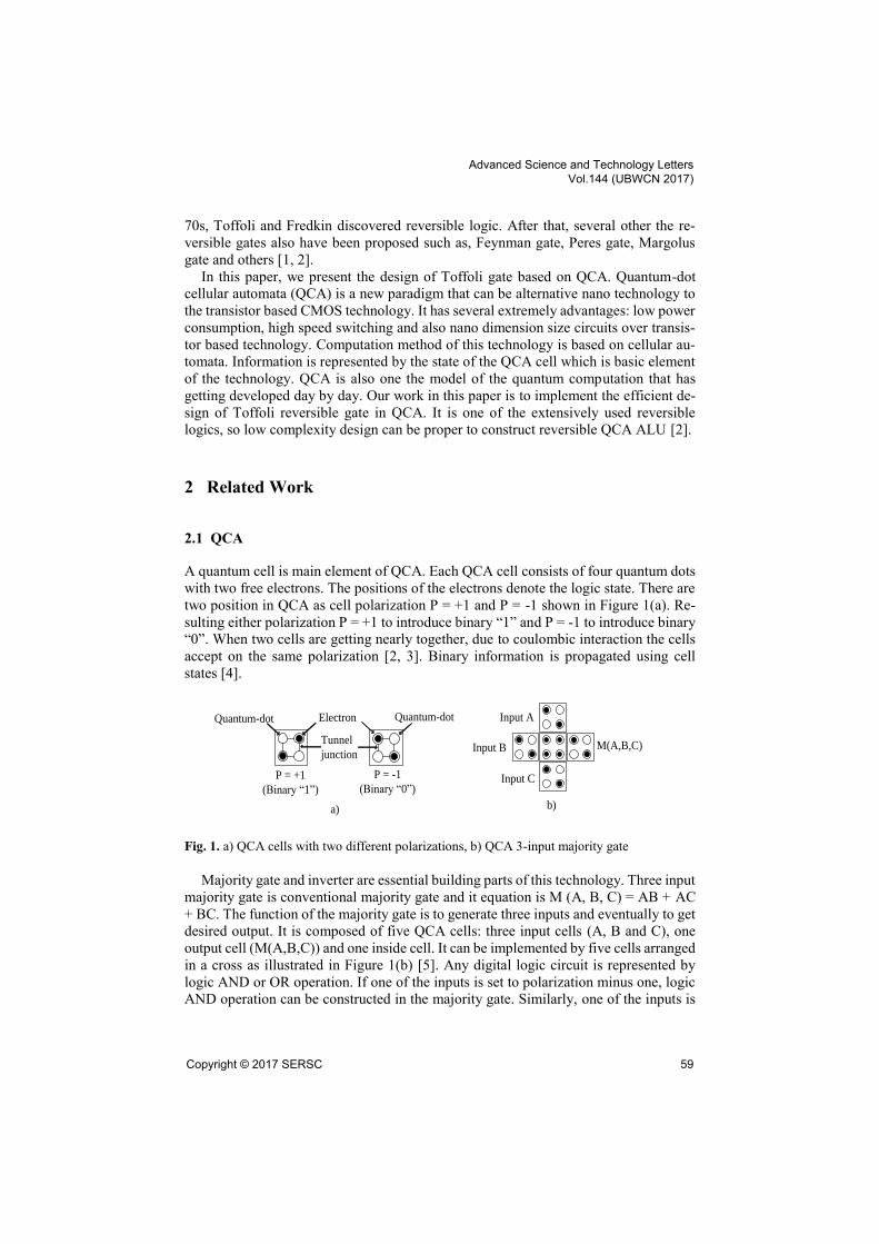
A quantum cell is main element of QCA. Each QCA cell consists of four quantum dots
with two free electrons. The positions of the electrons denote the logic state. There are
two position in QCA as cell polarization P = +1 and P = -1 shown in Figure 1(a). Re-
sulting either polarization P = +1 to introduce binary “1” and P = -1 to introduce binary
“0”. When two cells are getting nearly together, due to coulombic interaction the cells
accept on the same polarization [2, 3]. Binary information is propagated using cell
states [4].
Quantum-dot
P = +1
(Binary “1”)
P = -1
(Binary “0”)
Electron
Tunnel
junction
Quantum-dot Input A
Input B
Input C
M(A,B,C)
a) b)
Fig. 1. a) QCA cells with two different polarizations, b) QCA 3-input majority gate
Majority gate and inverter are essential building parts of this technology. Three input
majority gate is conventional majority gate and it equation is M (A, B, C) = AB + AC
+ BC. The function of the majority gate is to generate three inputs and eventually to get
desired output. It is composed of five QCA cells: three input cells (A, B and C), one
output cell (M(A,B,C)) and one inside cell. It can be implemented by five cells arranged
in a cross as illustrated in Figure 1(b) [5]. Any digital logic circuit is represented by
logic AND or OR operation. If one of the inputs is set to polarization minus one, logic
AND operation can be constructed in the majority gate. Similarly, one of the inputs is
Advanced Science and Technology Letters Vol.144 (UBWCN 2017)
Copyright © 2017 SERSC 59

set to polarization plus one, logic operation OR is constructed. Hence, any complex
logic circuits can be implemented from logic OR and logic AND gates respectively as:
𝐴 + 𝐵 = 𝑀(𝐴, 𝐵, 1); (1)
𝐴𝐵 = 𝑀(𝐴, 𝐵, 0); (2)
QCA wire is constructed with plural numbers of cells. By QCA wire information is
transfer cell by cell since electrostatic interaction. By placing cell with their edges con-
tact sequentially, simple QCA inverter is implemented. It is used to invert transferring
signal from one form to invers form, as shown in Figure 2(b). In this technology, wire
crossing is complicated point in the crossing two different wires. There are two types
of wire crossing, such as coplanar wire crossing technique and stereoscopic wire cross-
ing, namely multilayer form, as illustrated in Figure 2(a). For getting strong signal
strength, multilayer wire crossing is more proper than coplanar crossing which is com-
posed of rotated cells [5, 6]. However, there is another efficient form of coplanar wire
crossing and it is based on QCA clocking technique [5,6].
b)
Input=A Output=A`
a)
State: 0
State: 0
State: 1
State: 1
(Y)
(X)
State: 1State: 0
State: 1State: 0
(Y)
(X)
Input=A
Output=A`
Fig. 2. a) Typical wire-crossing techniques coplanar and multilayer crossover, b) QCA inverter
structures robust inverter and simple inverter.
QCA circuits use clock system for manage data transfer and synchronize. The main
advantage of QCA clock system is to provide the power to run the circuit because the
quantum cells are not exterior source for powering. QCA clock system makes use of
four phases clocking for regulating cells. It is realized by the steps: switch, hold, release
and relax phases, as demonstrated in Figure 3. As a mentioned before, QCA clocking
can be utilized in the wire crossing. QCA circuit is divided with four clock zones. The
zero zone(zone-0) cannot meet with zone two(zone-2), similarly, zone one(zone-1) can-
not meet with zone three(zone-3). By the concept, wire crossing can be realized in QCA
circuit easily[7,8].
Advanced Science and Technology Letters Vol.144 (UBWCN 2017)
60 Copyright © 2017 SERSC

Hold ReleaseSwitch RelaxClock
phase
Clocking
field
strength
Fig. 3. Clocking scheme
2.2 Toffoli Gate
The number of inputs and the number of outputs are equal to in reversible logic circuits
with one-to-one mapping between them. Number of 1’s in the inputs is equal to the
number of 1’s in the outputs. If the output is given, than it is possible to recover the
input [8]. Therefore, it is called reverse logic. The first reversible logic gate is 3x3 Tof-
foli gate and it is also known as controlled controlled-not. Its equations as follow: P=A,
Q=B, R=AB⊗C. Figure 4 illustrates the block diagram of the gate and its trust table,
respectively [6, 7, 8].
TOFFOLI
GATE
A
B
C
P=A
Q=B
R=AB⊕C
a) b)
Fig. 4. a) block diagram of Toffoli gate b) trust table of Toffoli gate
Advanced Science and Technology Letters Vol.144 (UBWCN 2017)
Copyright © 2017 SERSC 61
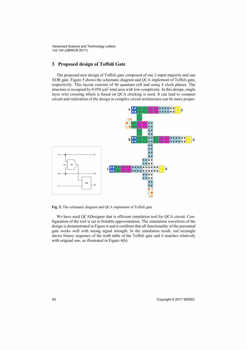
3 Proposed design of Toffoli Gate
The proposed new design of Toffoli gate composed of one 3-input majority and one
XOR gate. Figure 5 shows the schematic diagram and QCA implement of Toffoli gate,
respectively. This layout consists of 46 quantum cell and using 4 clock phases. The
structure is occupied by 0.058 µm2 total area with low complexity. In this design, single
layer wire crossing which is based on QCA clocking is used. It can lead to compact
circuit and realization of the design in complex circuit architecture can be more proper.
A
B
C
Q
P
XORR
MG-1.00
-1.00
R
-1.00
Q
PA
B
C
Fig. 5. The schematic diagram and QCA implement of Toffoli gate
We have used QCADesigner that is efficient simulation tool for QCA circuit. Con-
figuration of the tool is set to bistable approximation. The simulation waveform of the
design is demonstrated in Figure 6 and it confirms that all functionality of the presented
gate works well with strong signal strength. In the simulation result, red rectangle
shows binary sequence of the truth table of the Toffoli gate and it matches relatively
with original one, as illustrated in Figure 4(b).
Advanced Science and Technology Letters Vol.144 (UBWCN 2017)
62 Copyright © 2017 SERSC

Fig. 6. Simulation results of Taffoli Gate
Several prior works are discussed about Toffoli gate in QCA technology. Some of
them are misalignment to standard form of the reversible structure, such as less com-
plexity design [10, 11] is used less cells in his design, but one of the outputs is placed
inside of the structure. In the design [9], all construction way is by the rule of reversible
construction, but with more cell count and bigger occupation area. Table 1 shows com-
parison of the typical circuit with our circuit. Our design has achieved improvements
in terms of used cell count, total area as well as with regular construction way.
Table 1. Comparison result of Toffoli gates
Acknowledgments. This work was supported by the National Research Foundation of
Korea(NRF) grant funded by the Korea government(MSIP) (NO. NRF-
2015R1A2A1A15055749).
4 Conclusions
In this paper, less complexity reversible Taffoli gate has been presented in QCA tech-
nology. All functionality and correctness have been evaluated using QCADesigner tool
and the obtained results also have been compared with other existing works. The com-
parison table shows that the proposed design has achieved a large amount of improve-
ments on the space complexity such as the number of cells and total area. Actually the
Circuits Cell count Total area (µ𝑚2) Latency
Taffoli gate[9] 75 0.136 4
Taffoli gate[10] 57 0.060 3
Proposed design 46 0.058 4
Advanced Science and Technology Letters Vol.144 (UBWCN 2017)
Copyright © 2017 SERSC 63

latency of the circuit has been already small enough so that we focused on the space
and construction problem. Our circuit has excellent regularity and expandability so that
it could be an efficient component within configuration of a circuit.
References
1. C. Lent, P. Tougaw and W. Prod, “Quantum Cellular Automata: The physics of computing
with quantum dot molecules,” Physics and Computation, (1994), pp. 5-13.
2. J.C. Jeon, “Fundamental two-party quantum secret sharing protocol without quantum entan-
glement,” International Journal of Security and its Applications, vol.9, no.8, (2015), pp.293-
302.
3. J.C. Jeon: “Low Hardware Complexity QCA Decoding Architecture Using Inverter Chain,”
International Journal of Control and Automation, vol.9, no.4, (2016) pp.347-358
4. K. Navi, A. Roohi and S. Sayedsalehi, “Designing reconfigurable quantum dot cellular au-
tomata logic circuits,” International Journal of Computational and Theoretical Nanoscience,
vol.10, no.5, (2013), pp.1-10.
5. N. Safoev and J. C. Jeon, “Design of Barrel Shifter Based on Quantum-dot Cellular Autom-
ata,” 27th Research World International Conference, (2017), pp. 12-14.
6. T. Toffoli, “Reversible Computing,” MIT Laboratory for Computer Science, Technical re-
port, MIT/LCS/TM-151, MIT Lab for Computer Science (1980)
7. E. Fredkin and T. Toffoli, “Conservative logic,” The international journal of theoretical phys-
ics,vol.21, no.3, (1982) pp.219-253
8. J. C. Jeon, “Extendable quantum-dot Cellular automata decoding architecture using 5-input
majority gate”, International Journal of Control and Automation, vol. 8, no. 12, (2015), pp.
107-118.
9. A. Bahar, A. Habib and N. Biswas, “A Novel Presentation of Toffoli Gate in Quantum-dot
Cellular Automata (QCA),” International journal of computer applications (0975-8887), vol.
82, no. 10, (2013), pp. 1-4.
10. A. Shafi, Sh. Islam and N. Ali, “A Review on Reversible Logic Gates and its QCA imple-
mentation,” International journal of computer applications, vol. 128, no. 2, (2015) pp. 27-34.
11. J. Iqbal and M. T. Banday, “Applications of Toffoli gate for designing the classical gates
using quantum dot cellular automata,” International journal of recent scientific research, vol.
6, no, 12, (2015) pp. 7764-7769.
Advanced Science and Technology Letters Vol.144 (UBWCN 2017)
64 Copyright © 2017 SERSC
Recommended


![M toffoli socketteurocall_teacher_ed_sig_lyon[1]](https://img.pdfslide.net/doc/110x75/54786d78b4af9fa8378b4723/m-toffoli-socketteurocallteacheredsiglyon1.jpg)
