@DRZBM,Faculty Civil Engg.UiTM 1
Rock Excavation and Support
Systems
Refer to Handout
Factors Unique to Tunnelling
• Uncertainty in the nature and variability of ground conditions (rock quality, ground water, gas, etc) - need for adequate site investigations prior to and vigilance during tunnelling
• Confined space of tunnel environment (limited access, escape, air quality control)
• Difficulty in communications (sound and signal barriers)
• Work in compressed air (soft ground)
@DRZBM,Faculty Civil Engg.UiTM 2
EXCAVATION METHOD
BASED ON STRENGTH
/ WEATHERING GRADE,
QUALITY & FRACTURE
SPACING
Rock Excavation and Costruction
Methods
• Drill & Blast
• TBM – hard rock, feasibility use of TBM, type of TBM, cutter and backup equipment.
• NATM – construction involves special approach to both the construction and contracting method. Requires more comprehensive geotechnical data and anlysis to predict behaviour, classify ground condition, support system based on the anticipated behaviour. Ground condition becomes part of construction contract for pay items and selection of support system
@DRZBM,Faculty Civil Engg.UiTM 3
DRILL AND BLAST
METHOD
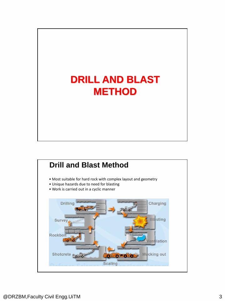
Drill and Blast Method
• Most suitable for hard rock with complex layout and geometry• Unique hazards due to need for blasting• Work is carried out in a cyclic manner

@DRZBM,Faculty Civil Engg.UiTM 4
Sequence of excavation
DRILL JUMBO MACHINE
Drilling
Drilling of Charge HolesThe number of hole depends on the cross-section of tunnel

@DRZBM,Faculty Civil Engg.UiTM 5
DRILL JUMBO MACHINE
Drilling
Drilling of Charge HolesArrangement of holes
Charging Explosive

@DRZBM,Faculty Civil Engg.UiTM 6
Hazards• accidental detonation by drilling into explosives• being knocked over or crushed by drilling boom• fallingProtection• Only charge after the whole face has been drilled• work can only be carried out under supervision of authorisedblasting specialist• use working platforms• Bulk emulsion
Charging Explosive
Charging
@DRZBM,Faculty Civil Engg.UiTM 7
Charging with Explosives
Holes drilled are next filled with explosives. This is done by miners standing on the
ground and, if the rock face is high, by using another jumbo with booms to lift the
miner.
Charging may be done using cartridge explosives, also known as stick powder or
dynamite.
The cartridges are placed in the holes and pushed to the back using a wooden
ramrod.
A waterproof detonator cord, or fuse, hangs out of the end of each hole.
The primer that starts the explosion is at the end of the fuse in the bottom of the
hole.
Charging may also be done using bulk explosives.
This granular material, commonly ammonium nitrate fuel oil, is blown by air into the
holes.
Again the fuse with a primer at the far end hangs from each hole.
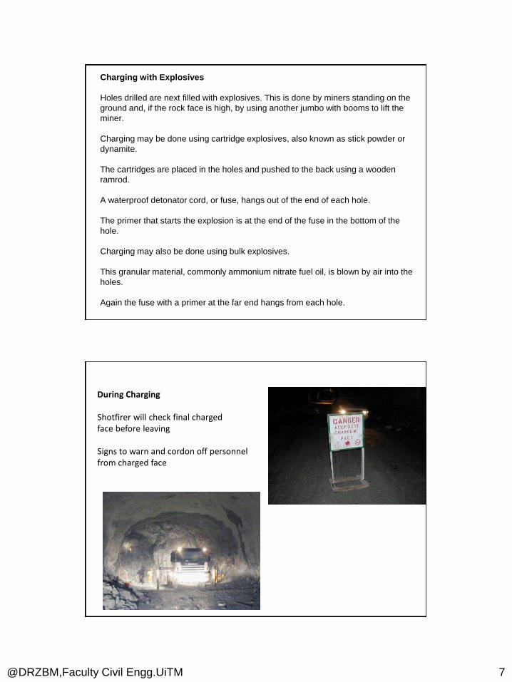
During Charging
Shotfirer will check final chargedface before leaving
Signs to warn and cordon off personnelfrom charged face
@DRZBM,Faculty Civil Engg.UiTM 8
Types of Emergency• Ground collapse (need we say more?)• Support failure• Flooding• Gas explosion• Oxygen deficiency• Fire (encountering inflammable gas)• Accidents : moving plants• Plant and power failure• Stoppage
Principal Causes of Accidents• Falling from heights or falling on level (tripping/slipping)• Materials falling from height or from stacks or vehicles• Burial by fall of material (rock collapse or stacking collapse)• Flooding or inrush of water• Machinery related (cranes, excavators, etc)• Vehicles (excavators, dump trucks)• Electrical installations• Fire and explosions (gas and explosives)• Air pollution (oxygen deficiency, toxic fumes & radon gas)
Hazards Related to Blasting•
@DRZBM,Faculty Civil Engg.UiTM 9
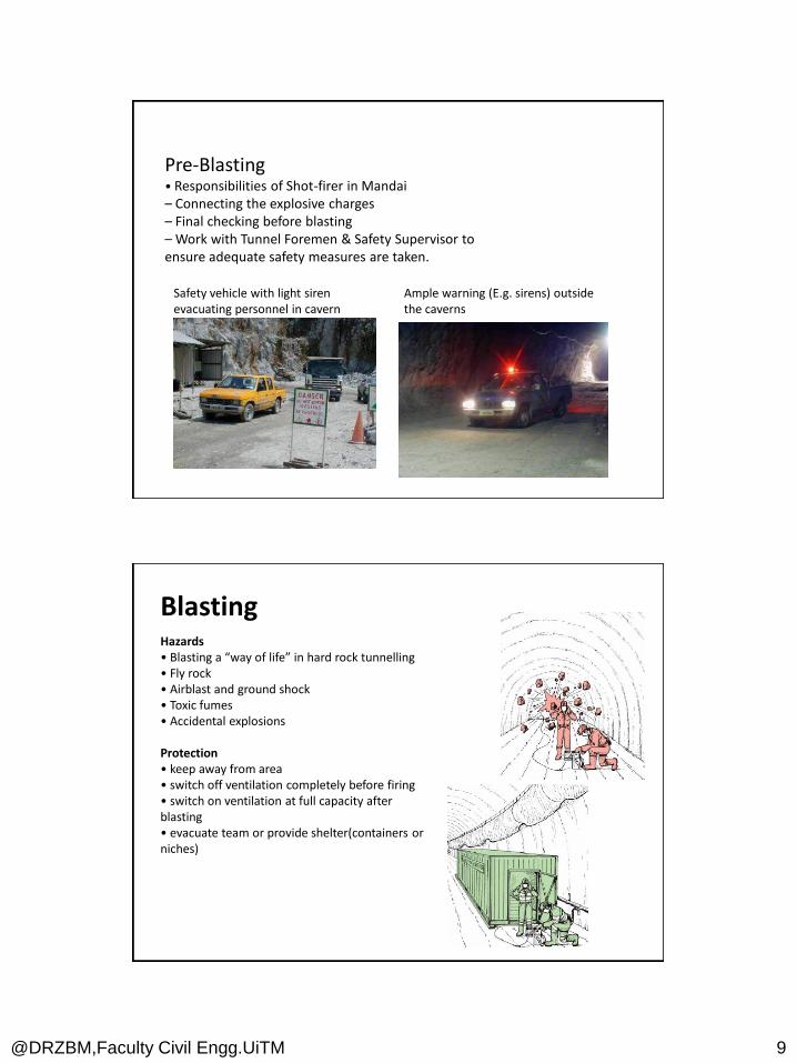
Pre-Blasting• Responsibilities of Shot-firer in Mandai– Connecting the explosive charges– Final checking before blasting– Work with Tunnel Foremen & Safety Supervisor toensure adequate safety measures are taken.
Safety vehicle with light sirenevacuating personnel in cavern
Ample warning (E.g. sirens) outsidethe caverns
BlastingHazards• Blasting a “way of life” in hard rock tunnelling• Fly rock• Airblast and ground shock• Toxic fumes• Accidental explosions
Protection• keep away from area• switch off ventilation completely before firing• switch on ventilation at full capacity after blasting• evacuate team or provide shelter(containers orniches)

@DRZBM,Faculty Civil Engg.UiTM 10
Inspection of Blast Results• Check for Misfires, Dangerous and Loose Rocks Conditions– Shotfirer and Tunnel Foreman will inspect the areacautiously for dangerous signs
• Safety Supervisor to ensure SF/TF carry out inspection –Should there be no initiation of explosives, minimum re-entry time must not be less than 30 mins.– After initiation, minimum retry time must not be less than 15mins (after ventilation)– Blast inspection team shall enter tunnel with appropriate breathing apparatus.
On-site Storage– Licensed magazine to store detonators and booster charges in temp cavern on site– Reduced transport hazards to public
Use of Bulk Emulsion– Non-explosives until being charged.– Less toxic fumes– Mechanised charging minimises human exposure at drilling face
Mobile Charging Unit
Use of Explosives
@DRZBM,Faculty Civil Engg.UiTM 11
Control of Dust and Fumes• Ventilation• Gas/dust monitoring• Minimum entry time after blasting (with ventilation)
Air Quality Underground• Oxygen deficiency• Dust• Toxic gas (CO, CO2, NO)• Heat and fire
Parameters for Air Monitoring– Oxygen – 19.5 to 23%– Nitrogen Dioxide – Less than 5ppm– Lower Explosive Limit – Less than 10%– Carbon Monoxide – Less than 25ppm– Dust – Less than 10mg/m3 (Long term)
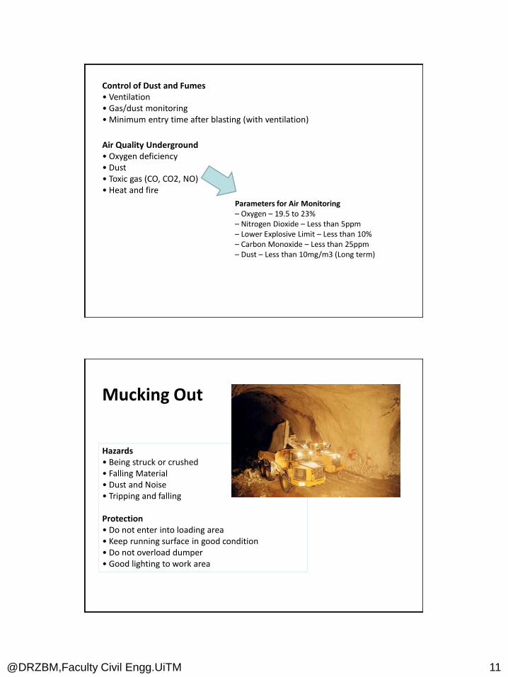
Hazards• Being struck or crushed• Falling Material• Dust and Noise• Tripping and falling
Protection• Do not enter into loading area • Keep running surface in good condition• Do not overload dumper• Good lighting to work area
Mucking Out
@DRZBM,Faculty Civil Engg.UiTM 12
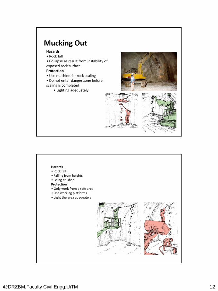
Hazards• Rock fall• Collapse as result from instability ofexposed rock surfaceProtection• Use machine for rock scaling• Do not enter danger zone beforescaling is completed
• Lighting adequately
Mucking Out
Hazards• Rock fall• Falling from heights• Being crushedProtection• Only work from a safe area• Use working platforms• Light the area adequately
@DRZBM,Faculty Civil Engg.UiTM 13
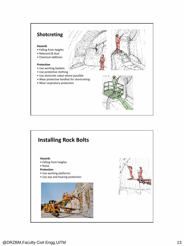
Shotcreting
Hazards• Falling from heights• Rebound & dust• Chemical additives
Protection• Use working baskets• Use protective clothing• Use shotcrete robot where possible• Wear protective hardhat for shortcreting• Wear respiratory protection
Hazards• Falling from heights• NoiseProtection• Use working platforms• Use eye and hearing protection
Installing Rock Bolts

@DRZBM,Faculty Civil Engg.UiTM 14
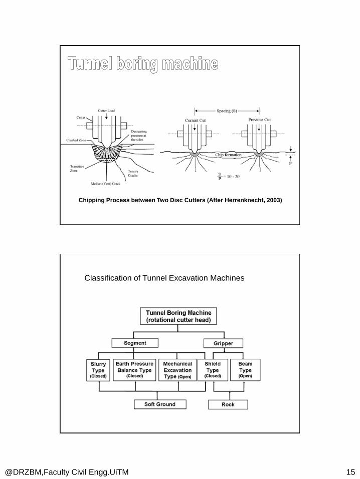
TBM
Tunnel boring machines (TBM) excavate rock mass in a
form of rotating and crushing by applying enormous
pressure on the face with large thrust forces while rotating
and chipping with a number of disc cutters mounted on the
machine face (cutterhead)
@DRZBM,Faculty Civil Engg.UiTM 15
Chipping Process between Two Disc Cutters (After Herrenknecht, 2003)
Classification of Tunnel Excavation Machines
@DRZBM,Faculty Civil Engg.UiTM 16
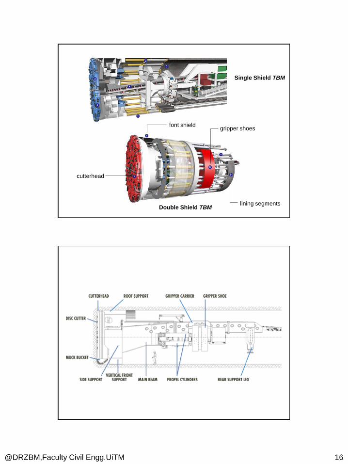
cutterhead
font shieldgripper shoes
lining segments
Single Shield TBM
Double Shield TBM
@DRZBM,Faculty Civil Engg.UiTM 17

@DRZBM,Faculty Civil Engg.UiTM 18
NATM

@DRZBM,Faculty Civil Engg.UiTM 19
When NATM is seen as a construction method, the key features are:
The tunnel is sequentially excavated and supported, and the excavation sequences can be varied.
The initial ground support is provided by shotcrete in combination with fibre or welded-wire fabric reinforcement, steel arches (usually lattice girders), and sometimes ground reinforcement (e.g. soil nails, spiling).
The permanent support is usually (but not always) a cast-in-place concrete lining.
The NATM integrates the principles of the behaviour of rock masses under load and monitoring the performance of underground construction during construction.
The NATM is not a set of specific excavation and support techniques and has often been referred to as a "design as you go" approach to tunnelling providing an optimized support based on observed ground conditions but more correctly it is a "design as you monitor" approach based on observed convergence and divergence in the lining as well as prevailing rock conditions.
@DRZBM,Faculty Civil Engg.UiTM 20
There are seven features on which NATM is based:
Mobilization of the strength of rock mass - The method relies on the inherent strength of the surrounding rock mass being conserved as the main component of tunnel support. Primary support is directed to enable the rock to support itself.
Shotcrete protection - Loosening and excessive rock deformation must be minimised. This is achieved by applying a thin layer of shotcrete immediately after face advance.
Measurements - Every deformation of the excavation must be measured. NATM requires installation of sophisticated measurement instrumentation. It is embedded in lining, ground, and boreholes.
Flexible support - The primary lining is thin and reflects recent strataconditions. Active rather than passive support is used and the tunnel is strengthened not by a thicker concrete lining but by a flexible combination of rock bolts, wire mesh and steel ribs.
Closing of invert - Quickly closing the invert and creating a load-bearing ring is important. It is crucial in soft ground tunnels where no section of the tunnel should be left open even temporarily.
Contractual arrangements - Since the NATM is based on monitoringmeasurements, changes in support and construction method are possible. This is possible only if the contractual system enables those changes.
Rock mass classification determines support measures - There are several main rock classes for tunnels and corresponding support systems for each. These serve as the guidelines for tunnel reinforcement.
@DRZBM,Faculty Civil Engg.UiTM 21
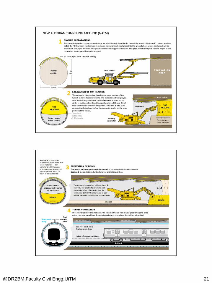
NEW AUSTRIAN TUNNELING METHOD (NATM)

@DRZBM,Faculty Civil Engg.UiTM 22
SUPPORT SYSTEM
@DRZBM,Faculty Civil Engg.UiTM 23
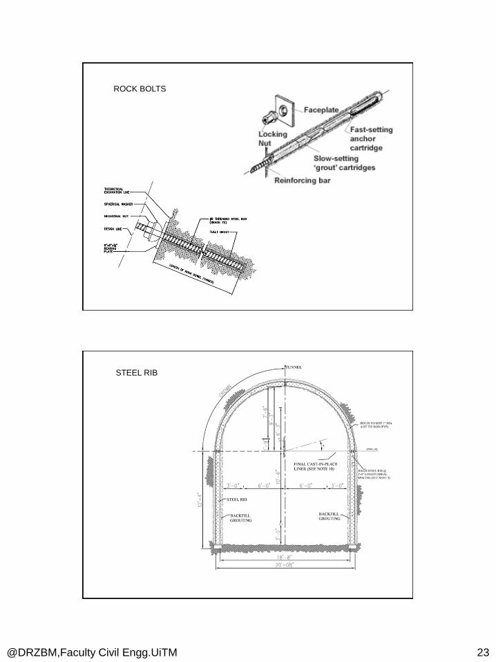
ROCK BOLTS
STEEL RIB
@DRZBM,Faculty Civil Engg.UiTM 24
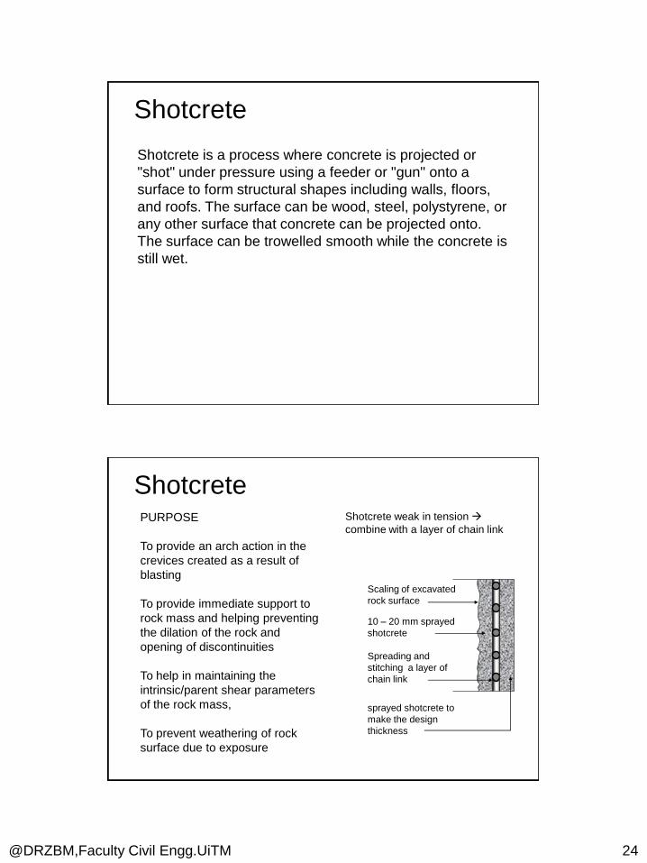
Shotcrete is a process where concrete is projected or
"shot" under pressure using a feeder or "gun" onto a
surface to form structural shapes including walls, floors,
and roofs. The surface can be wood, steel, polystyrene, or
any other surface that concrete can be projected onto.
The surface can be trowelled smooth while the concrete is
still wet.
Shotcrete
ShotcretePURPOSE
To provide an arch action in the
crevices created as a result of
blasting
To provide immediate support to
rock mass and helping preventing
the dilation of the rock and
opening of discontinuities
To help in maintaining the
intrinsic/parent shear parameters
of the rock mass,
To prevent weathering of rock
surface due to exposure
Shotcrete weak in tension
combine with a layer of chain link
Scaling of excavated
rock surface
Spreading and
stitching a layer of
chain link
10 – 20 mm sprayed
shotcrete
sprayed shotcrete to
make the design
thickness

@DRZBM,Faculty Civil Engg.UiTM 25
Wet Mix - All ingredients, including water, are thoroughly mixed
and introduced into the delivery equipment. Wet material is
pumped to the nozzle where compressed air is added to
provide high velocity for placement and consolidation of the
material onto the receiving surface.
Dry Mix - Pre-blended dry or damp materials are placed into
the delivery equipment. Compressed air conveys material
through a hose at high velocity to the nozzle, where water is
added. Material is consolidated on the receiving surface by
the high-impact velocity.
Shotcrete
DRY SHOTCRETE
The equipment being lighter, the shotcreting
can be done in poorly approachable areas as
well
Less power inputs is required
Low initial cost, low maintenance and cheaper
The process is dusty
Productivity is comparatively low
Quality control is relatively poorer since
addition of water is done by the nozzle man
Accessibility of nozzle with the respect to
surface is power
Rebound is greater
WET SHOTCRETE
Proper approach is required for
deploying the machine
Greater power is required for the
operation
Costlier process
The process is much cleaner
Higher productivity (about 10 to 16
cum/h
Quality control is better
Accessibility is better in case of use
of robot arm
Rebound is less

@DRZBM,Faculty Civil Engg.UiTM 26
Shot-crete Equipment
Recommended