RT-WiFi: Real-Time High-Speed Communication Protocol for
Wireless Cyber-Physical Control Applications
1
Yi-Hung Wei†, Quan Leng†, Song Han‡, Aloysius K. Mok†,
Wenlong Zhang§, Masayoshi Tomizuka§
†Department of Computer Science, The University of Texas at Austin
‡Department of Computer Science and Engineering, University of Connecticut
§Department of Mechanical Engineering, University of California, Berkeley
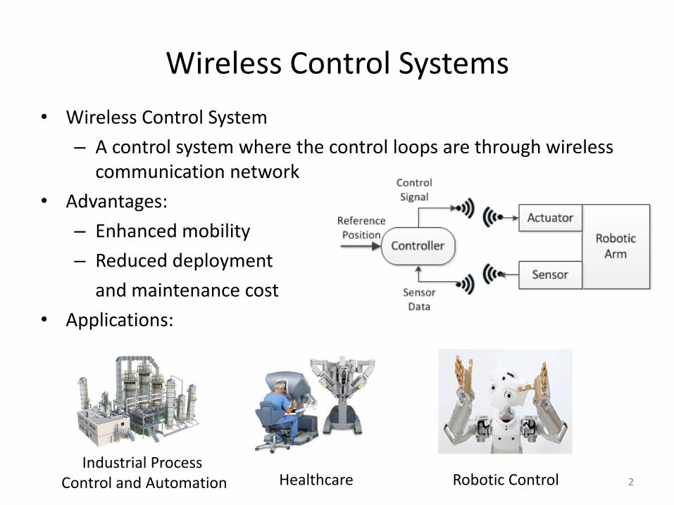
Wireless Control Systems
• Wireless Control System
– A control system where the control loops are through wireless communication network
• Advantages:
– Enhanced mobility
– Reduced deployment
and maintenance cost
• Applications:
2
Industrial Process Control and Automation Healthcare Robotic Control
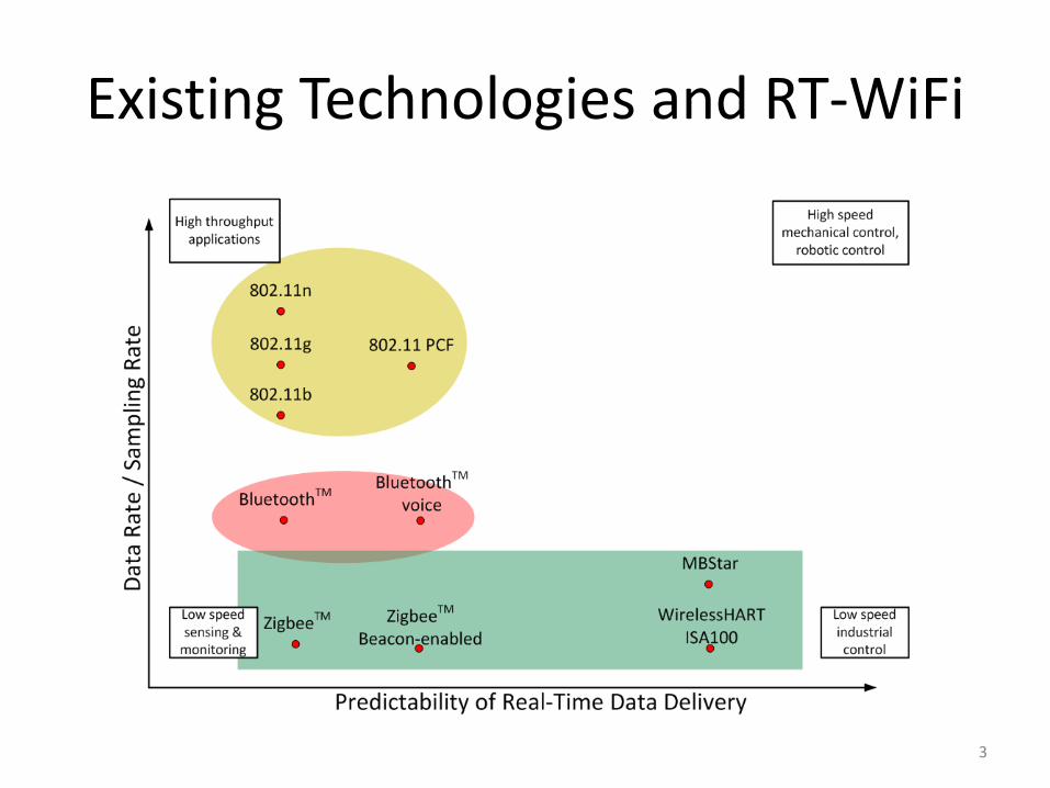
Existing Technologies and RT-WiFi
3
Outline
• Introduction
• RT-WiFi Design
• Performance Evaluation
• Case Study
• Conclusion and Future Work
4
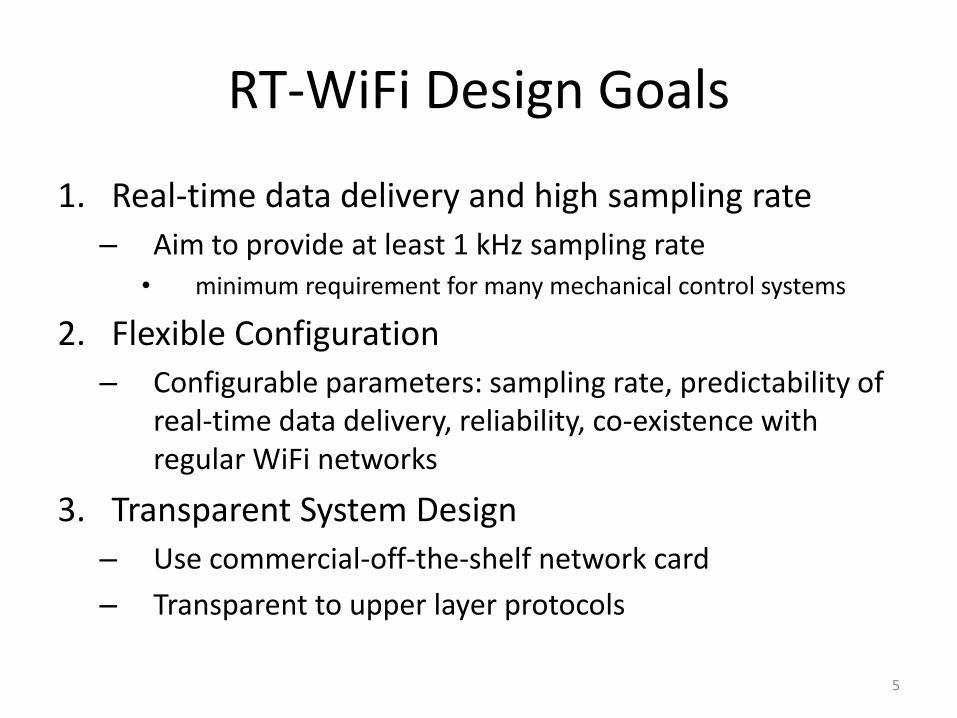
1. Real-time data delivery and high sampling rate
– Aim to provide at least 1 kHz sampling rate • minimum requirement for many mechanical control systems
2. Flexible Configuration
– Configurable parameters: sampling rate, predictability of real-time data delivery, reliability, co-existence with regular WiFi networks
3. Transparent System Design
– Use commercial-off-the-shelf network card
– Transparent to upper layer protocols
5
RT-WiFi Design Goals
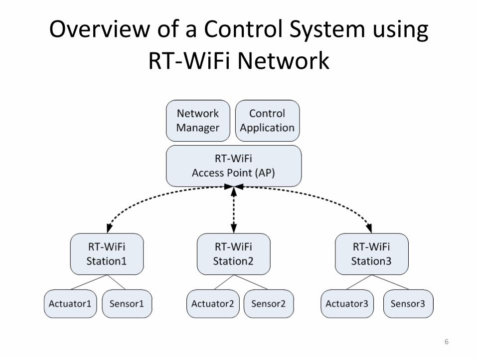
Overview of a Control System using RT-WiFi Network
6
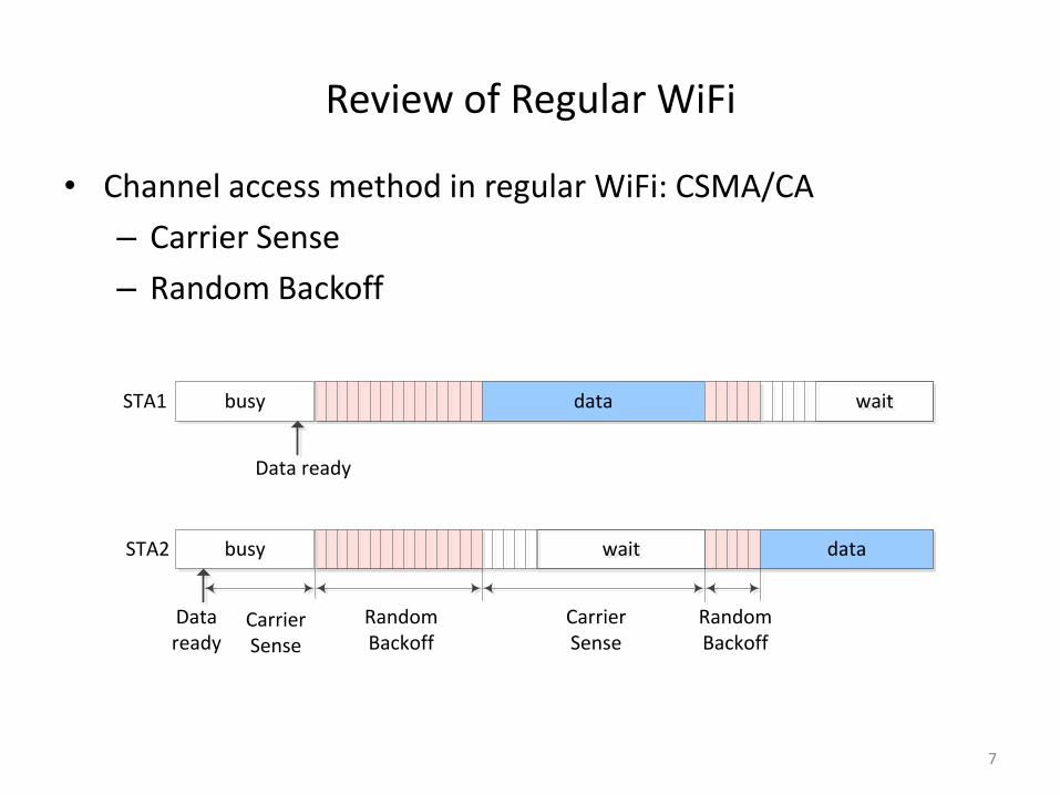
• Channel access method in regular WiFi: CSMA/CA
– Carrier Sense
– Random Backoff
7
Review of Regular WiFi
data
datawaitwait
waitwait
STA2
STA1 busy
busy
Data ready
Data ready
Random Backoff
Random Backoff
Carrier Sense
Carrier Sense
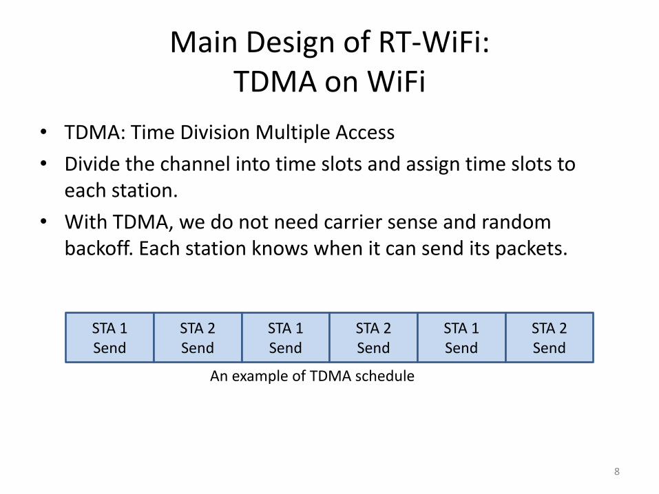
Main Design of RT-WiFi: TDMA on WiFi
• TDMA: Time Division Multiple Access
• Divide the channel into time slots and assign time slots to each station.
• With TDMA, we do not need carrier sense and random backoff. Each station knows when it can send its packets.
8
STA 1 Send
STA 2 Send
STA 1 Send
STA 2 Send
STA 1 Send
STA 2 Send
An example of TDMA schedule
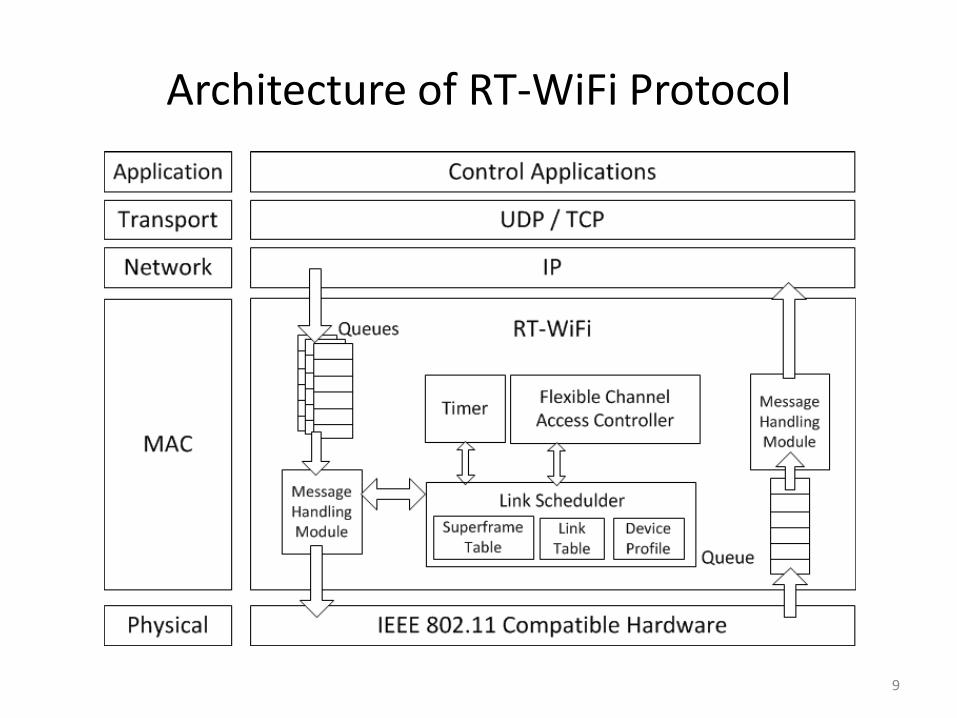
Architecture of RT-WiFi Protocol
9
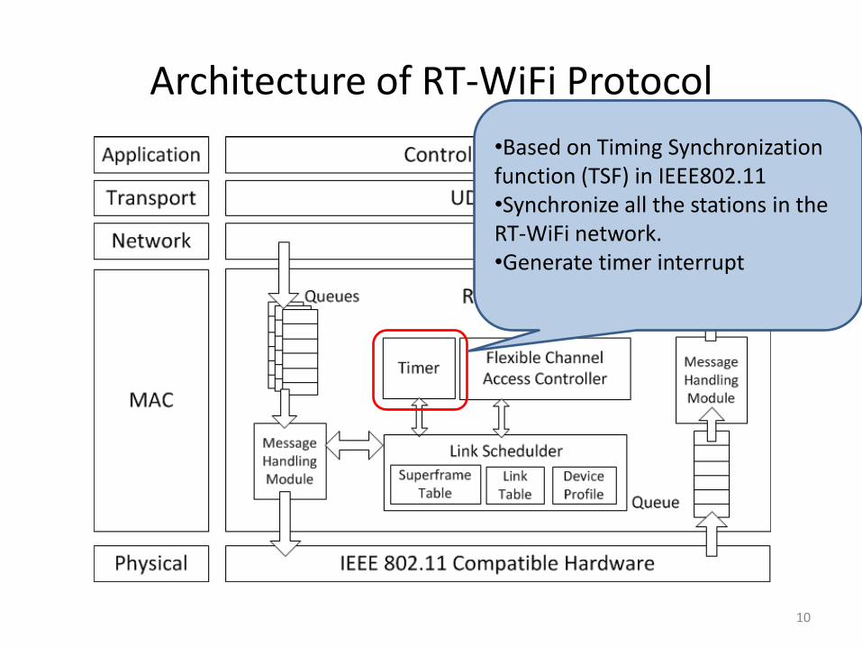
Architecture of RT-WiFi Protocol
10
•Based on Timing Synchronization function (TSF) in IEEE802.11 •Synchronize all the stations in the RT-WiFi network. •Generate timer interrupt
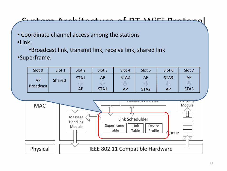
System Architecture of RT-WiFi Protocol
11
• Coordinate channel access among the stations •Link:
•Broadcast link, transmit link, receive link, shared link •Superframe:
Slot 0
AP Broadcast
Shared
Slot 1 Slot 2 Slot 3 Slot 4 Slot 5 Slot 6 Slot 7
STA1
AP
STA2
AP
STA3
AP
AP
STA1
AP
STA2
AP
STA3
System Architecture of RT-WiFi Protocol
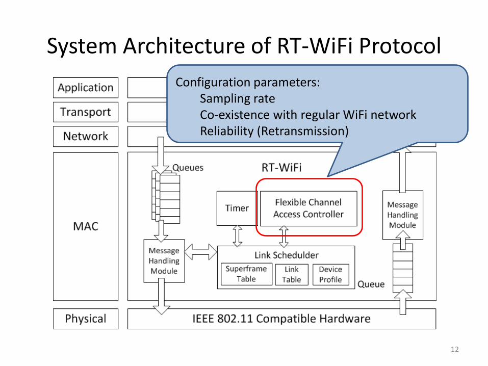
12
Configuration parameters: Sampling rate Co-existence with regular WiFi network Reliability (Retransmission)
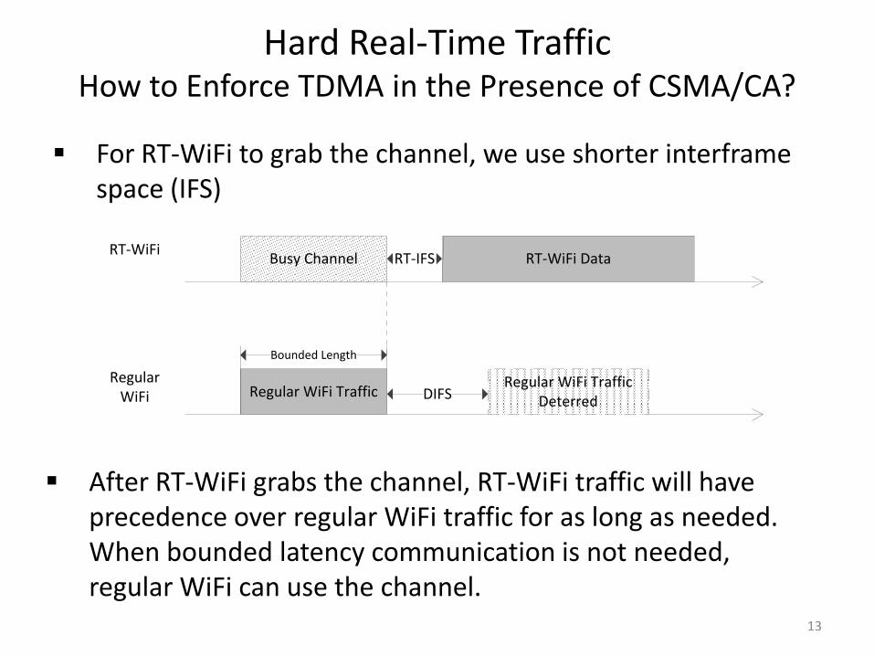
Hard Real-Time Traffic How to Enforce TDMA in the Presence of CSMA/CA?
13
For RT-WiFi to grab the channel, we use shorter interframe space (IFS)
After RT-WiFi grabs the channel, RT-WiFi traffic will have precedence over regular WiFi traffic for as long as needed. When bounded latency communication is not needed, regular WiFi can use the channel.
RT-IFSBusy Channel RT-WiFi Data
DIFSRegular WiFi TrafficRegular WiFi Traffic
Deterred
Bounded Length
RT-WiFi
Regular WiFi
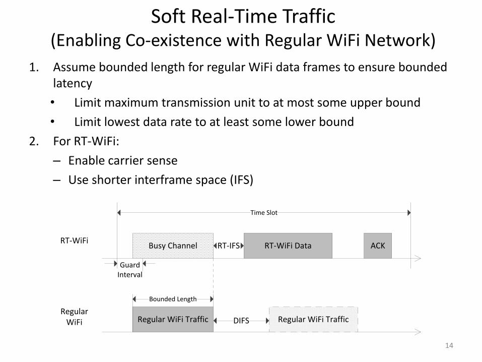
Soft Real-Time Traffic (Enabling Co-existence with Regular WiFi Network)
14
1. Assume bounded length for regular WiFi data frames to ensure bounded latency
• Limit maximum transmission unit to at most some upper bound
• Limit lowest data rate to at least some lower bound
2. For RT-WiFi:
– Enable carrier sense
– Use shorter interframe space (IFS)
Guard Interval
RT-IFS
Time Slot
Busy Channel RT-WiFi Data ACK
DIFSRegular WiFi Traffic Regular WiFi Traffic
Bounded Length
RT-WiFi
Regular WiFi
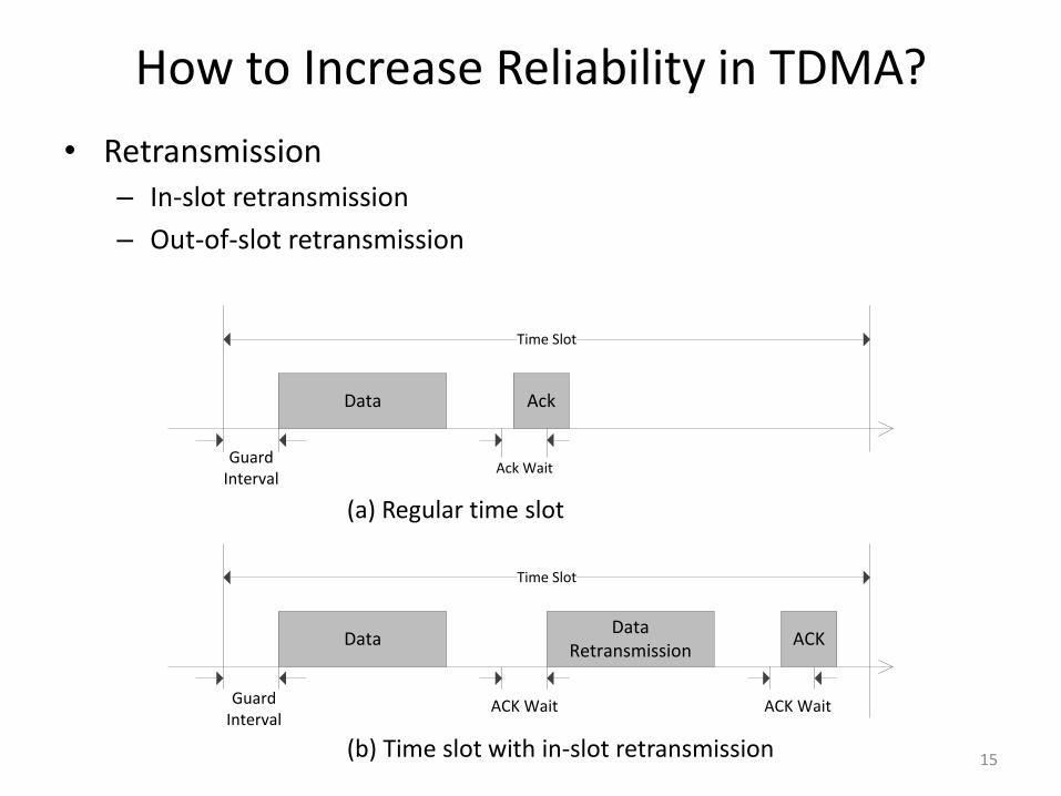
How to Increase Reliability in TDMA?
• Retransmission – In-slot retransmission
– Out-of-slot retransmission
15
(a) Regular time slot
(b) Time slot with in-slot retransmission
Guard Interval
Time Slot
Data Ack
Ack Wait
Guard Interval
Time Slot
Data ACK
ACK Wait
Data Retransmission
ACK Wait
Outline
• Introduction
• RT-WiFi Design
• Performance Evaluation
• Case Study
• Conclusion and Future Work
16
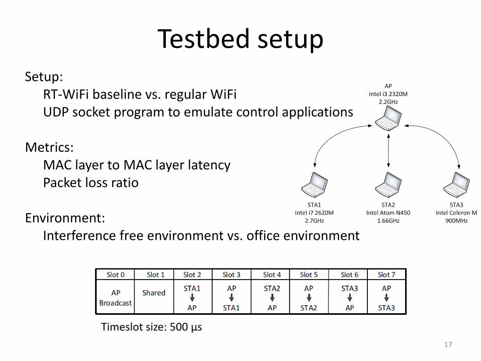
Testbed setup
17
Setup: RT-WiFi baseline vs. regular WiFi UDP socket program to emulate control applications Metrics: MAC layer to MAC layer latency Packet loss ratio Environment: Interference free environment vs. office environment
Timeslot size: 500 μs
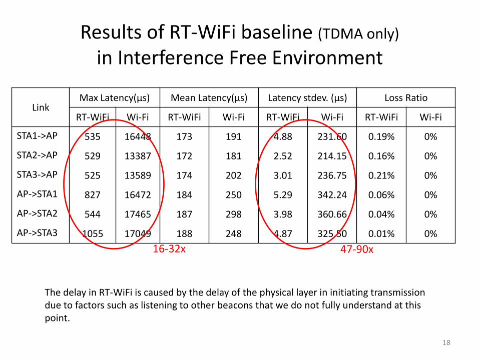
Results of RT-WiFi baseline (TDMA only)
in Interference Free Environment
Link Max Latency(μs) Mean Latency(μs) Latency stdev. (μs) Loss Ratio
RT-WiFi Wi-Fi RT-WiFi Wi-Fi RT-WiFi Wi-Fi RT-WiFi Wi-Fi
STA1->AP 535 16448 173 191 4.88 231.60 0.19% 0%
STA2->AP 529 13387 172 181 2.52 214.15 0.16% 0%
STA3->AP 525 13589 174 202 3.01 236.75 0.21% 0%
AP->STA1 827 16472 184 250 5.29 342.24 0.06% 0%
AP->STA2 544 17465 187 298 3.98 360.66 0.04% 0%
AP->STA3 1055 17049 188 248 4.87 325.50 0.01% 0%
18
16-32x 47-90x
The delay in RT-WiFi is caused by the delay of the physical layer in initiating transmission due to factors such as listening to other beacons that we do not fully understand at this point.
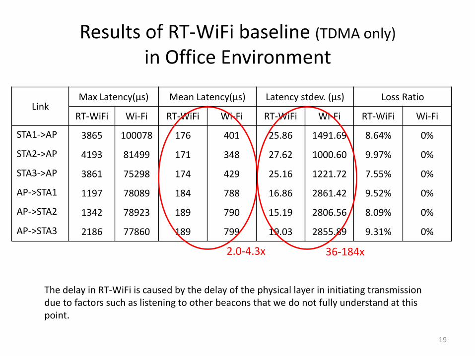
Results of RT-WiFi baseline (TDMA only)
in Office Environment
19
Link Max Latency(μs) Mean Latency(μs) Latency stdev. (μs) Loss Ratio
RT-WiFi Wi-Fi RT-WiFi Wi-Fi RT-WiFi Wi-Fi RT-WiFi Wi-Fi
STA1->AP 3865 100078 176 401 25.86 1491.69 8.64% 0%
STA2->AP 4193 81499 171 348 27.62 1000.60 9.97% 0%
STA3->AP 3861 75298 174 429 25.16 1221.72 7.55% 0%
AP->STA1 1197 78089 184 788 16.86 2861.42 9.52% 0%
AP->STA2 1342 78923 189 790 15.19 2806.56 8.09% 0%
AP->STA3 2186 77860 189 799 19.03 2855.89 9.31% 0%
36-184x 2.0-4.3x
The delay in RT-WiFi is caused by the delay of the physical layer in initiating transmission due to factors such as listening to other beacons that we do not fully understand at this point.
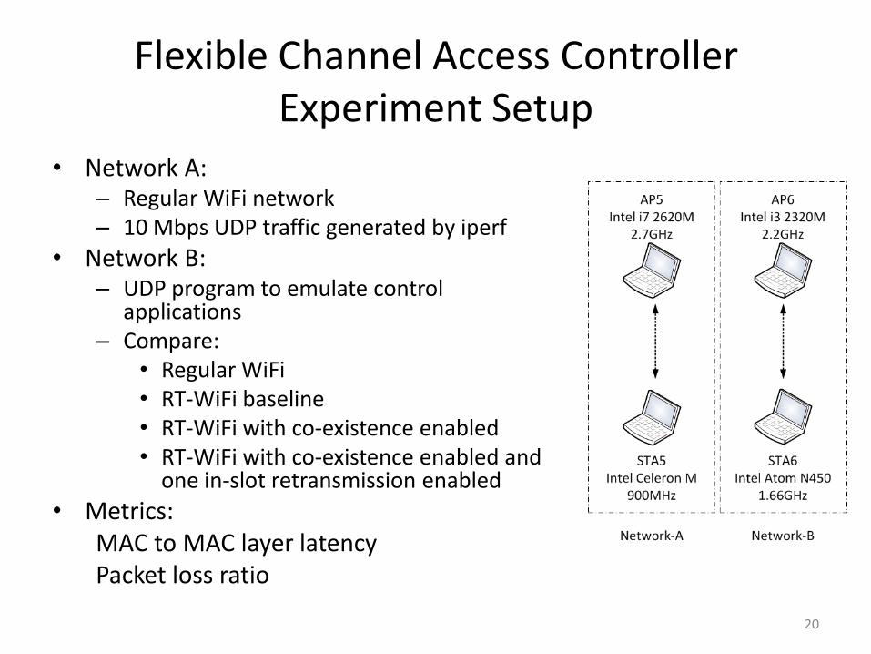
• Network A: – Regular WiFi network – 10 Mbps UDP traffic generated by iperf
• Network B: – UDP program to emulate control
applications – Compare:
• Regular WiFi • RT-WiFi baseline • RT-WiFi with co-existence enabled • RT-WiFi with co-existence enabled and
one in-slot retransmission enabled
• Metrics: MAC to MAC layer latency Packet loss ratio
20
Flexible Channel Access Controller Experiment Setup
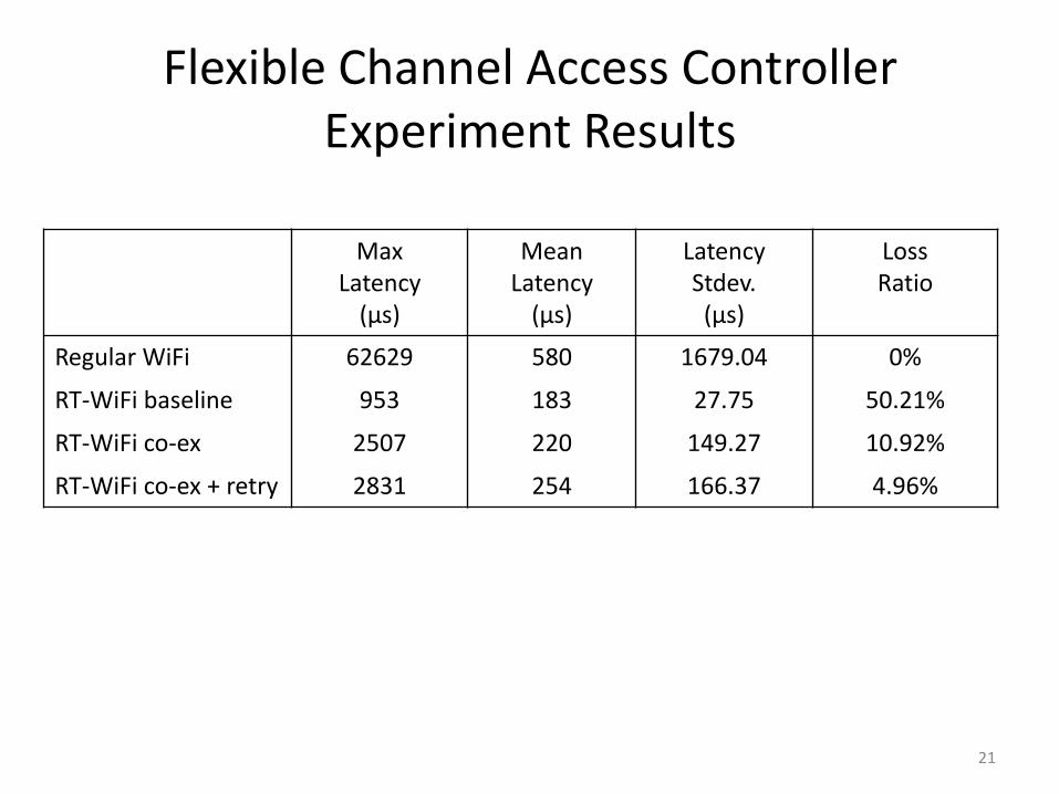
Flexible Channel Access Controller Experiment Results
Max Latency
(μs)
Mean Latency
(μs)
Latency Stdev. (μs)
Loss Ratio
Regular WiFi 62629 580 1679.04 0%
RT-WiFi baseline 953 183 27.75 50.21%
RT-WiFi co-ex 2507 220 149.27 10.92%
RT-WiFi co-ex + retry 2831 254 166.37 4.96%
21
Outline
• Introduction
• RT-WiFi Design
• Performance Evaluation
• Case Study
• Conclusion and Future Work
22
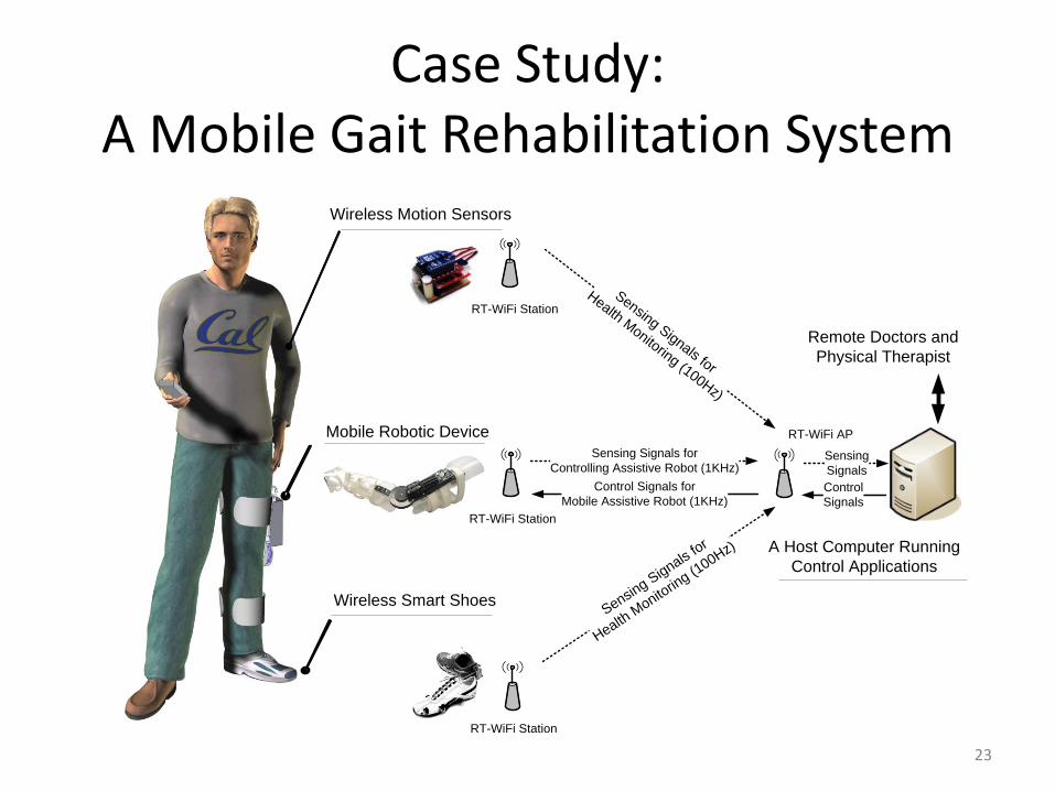
Case Study: A Mobile Gait Rehabilitation System
23
Wireless Motion Sensors
Mobile Robotic Device
Wireless Smart Shoes
A Host Computer Running
Control Applications
Remote Doctors and
Physical Therapist
Sensing Signals for
Health Monitoring (100Hz)
Sensing S
ignals for
Health M
onitorin
g (100Hz)
Sensing Signals for
Controlling Assistive Robot (1KHz)
Control
Signals
RT-WiFi Station
RT-WiFi Station
RT-WiFi Station
RT-WiFi AP
Control Signals for
Mobile Assistive Robot (1KHz)
Sensing
Signals
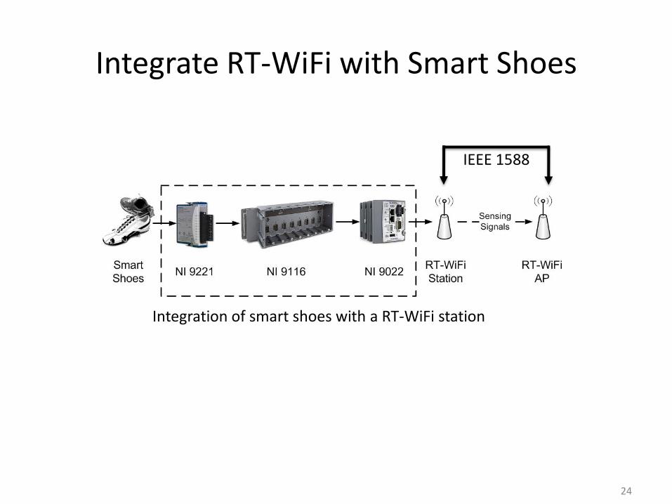
Integrate RT-WiFi with Smart Shoes
24
Integration of smart shoes with a RT-WiFi station
IEEE 1588
25
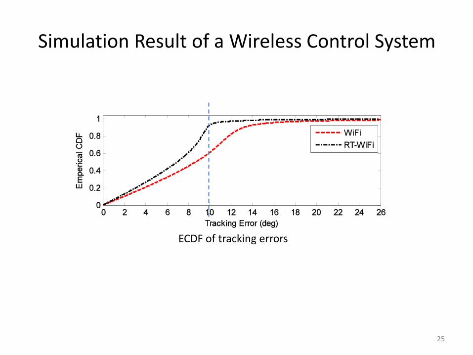
Simulation Result of a Wireless Control System
ECDF of tracking errors
Outline
• Introduction
• RT-WiFi Design
• Performance Evaluation
• Case Study
• Conclusion and Future Work
26
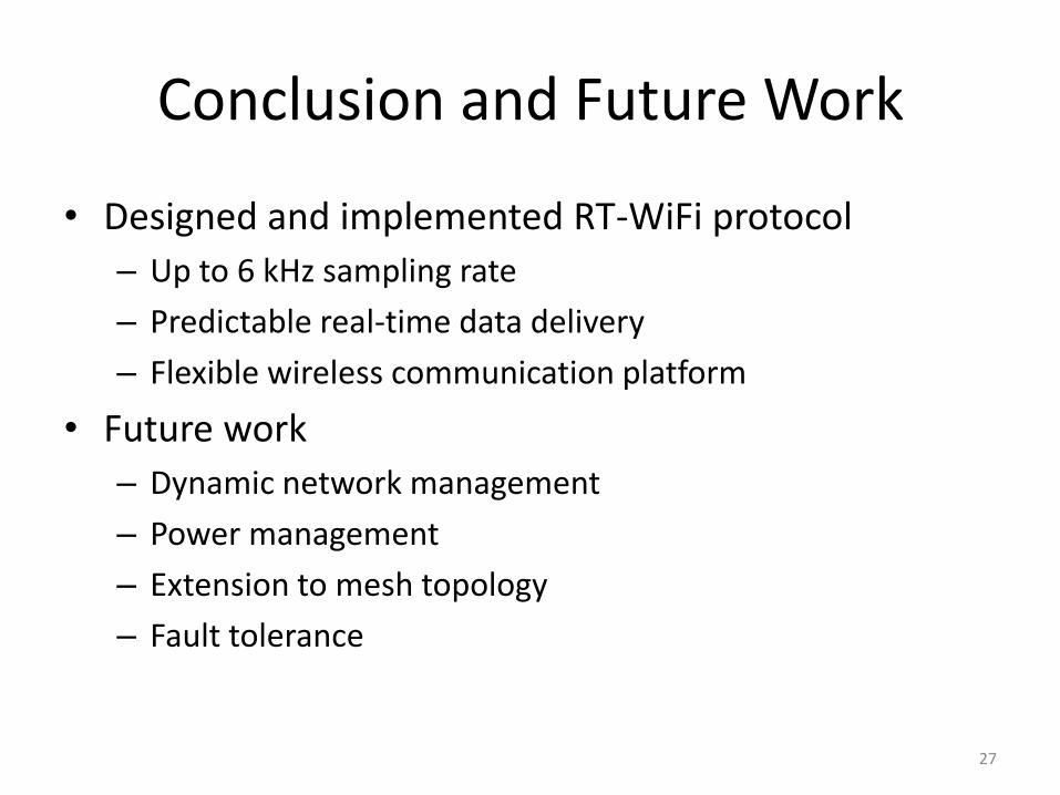
Conclusion and Future Work
• Designed and implemented RT-WiFi protocol
– Up to 6 kHz sampling rate
– Predictable real-time data delivery
– Flexible wireless communication platform
• Future work
– Dynamic network management
– Power management
– Extension to mesh topology
– Fault tolerance
27

Thanks &
Questions?
28
References
• [1] Y.-H. Wei, Q. Leng, S. Han, A. K. Mok, W. Zhang, and M. Tomizuka, “RT-WiFi: Real-Time High-Speed Communication Protocol for Wireless Cyber-Physical Control Applications”, Technical Report http://www.cs.utexas.edu/users/yhwei/pub/rt-wifi-TR.pdf.
• [2] J. Song, S. Han, A. K. Mok, D. Chen, M. Lucas, M. Nixon, and W. Pratt, “WirelessHART: Applying wireless technology in real-time industrial process control”, in IEEE Real-Time and Embedded Technology and Applications Symposium (RTAS), 2008, pp. 377-386.
• [3] W. Zhang, X, Zhu, S. Han, N. Byl, A. K. Mok, and M. Tomizuka, “Design of a network-based gait rehabilitation system,” in IEEE International Conference on Robotics and Biomimetics (ROBIO), 2012, pp. 1773-1778.
• [4] S. Han, A. K. Mok, J. Meng, Y.-H. Wei, P.-C. Huang, Q. Leng, X. Zhu, L. Sentis, K. S. Kim, and R. Miikkulainen, “Architecture of a cyberphysical avatar”, in International Conference on Cyber-Physical Systems (ICCPS), 2013.
29
References
• [5] Y.-H. Wei, Q. Leng, S. Han, A. K. Mok, W. Zhang, M. Tomizuka, T. Li, D. Leith, and D. Malone, “RT-WiFi: Real-time high speed communication protocol for wireless control systems”, in IEEE Real-Time Systems Symposium Work-in-Progress Session (RTSS WiP), 2012.
• [6] “ISA 100”, http://www.isa.org/isa100.
• [7] X. Zhu, S. Han, P.-C. Huang, A. K. Mok, and D. Chen, “MBstar: A real-time communication protocol for wireless body area networks”, in IEEE Euromicro Conference on Real-Time Systems (ECRTS), 2011, pp. 57-66.
• [8] “IEEE 802.11 working group”, http://www.ieee802.org/11/.
• [9] J. C. Eidson, Measurement, control and communication using IEEE1588, Springer Publishing Company, Incorporated, 2010.
30

Backup Slides
31
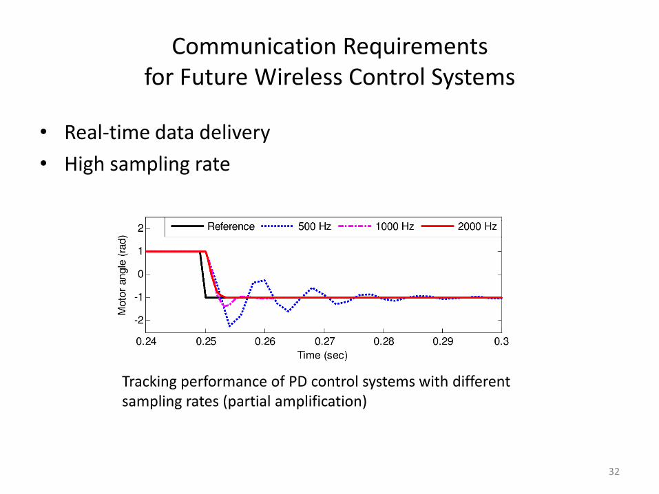
Communication Requirements for Future Wireless Control Systems
• Real-time data delivery
• High sampling rate
32
Tracking performance of PD control systems with different sampling rates (partial amplification)
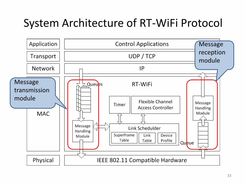
System Architecture of RT-WiFi Protocol
33
Message transmission module
Message reception module
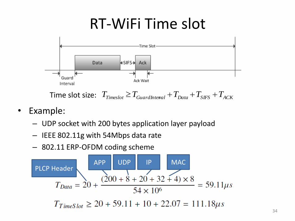
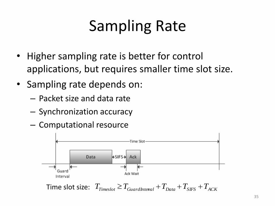
RT-WiFi Time slot
34
ACKSIFSDatavalGuardInterTimeslot TTTTT Time slot size:
• Example: – UDP socket with 200 bytes application layer payload
– IEEE 802.11g with 54Mbps data rate
– 802.11 ERP-OFDM coding scheme
PLCP Header APP UDP IP MAC
Sampling Rate
• Higher sampling rate is better for control applications, but requires smaller time slot size.
• Sampling rate depends on:
– Packet size and data rate
– Synchronization accuracy
– Computational resource
35
ACKSIFSDatavalGuardInterTimeslot TTTTT Time slot size:
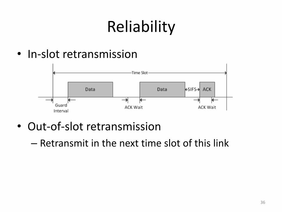
Reliability
• In-slot retransmission
• Out-of-slot retransmission
– Retransmit in the next time slot of this link
36
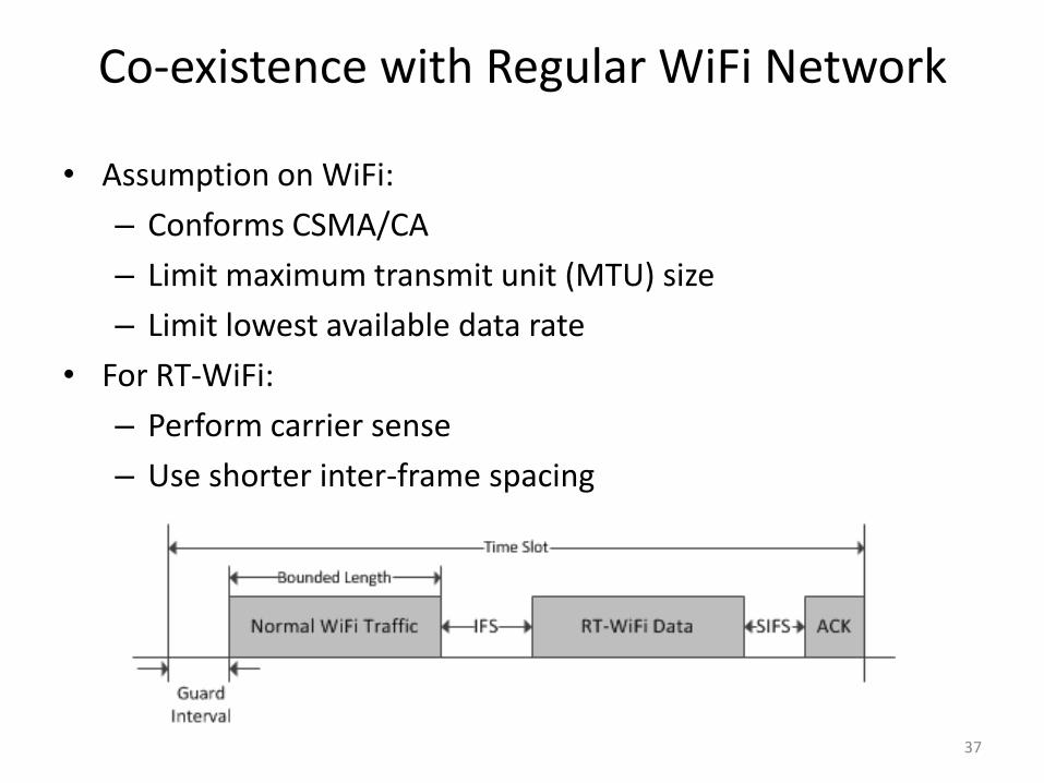
Co-existence with Regular WiFi Network
• Assumption on WiFi:
– Conforms CSMA/CA
– Limit maximum transmit unit (MTU) size
– Limit lowest available data rate
• For RT-WiFi:
– Perform carrier sense
– Use shorter inter-frame spacing
37
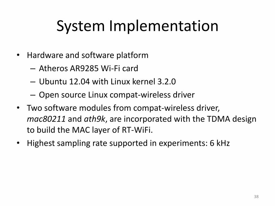
System Implementation
• Hardware and software platform
– Atheros AR9285 Wi-Fi card
– Ubuntu 12.04 with Linux kernel 3.2.0
– Open source Linux compat-wireless driver
• Two software modules from compat-wireless driver, mac80211 and ath9k, are incorporated with the TDMA design to build the MAC layer of RT-WiFi.
• Highest sampling rate supported in experiments: 6 kHz
38
39
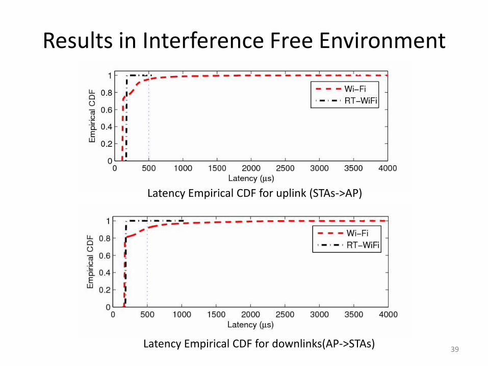
Results in Interference Free Environment
Latency Empirical CDF for uplink (STAs->AP)
Latency Empirical CDF for downlinks(AP->STAs)
40
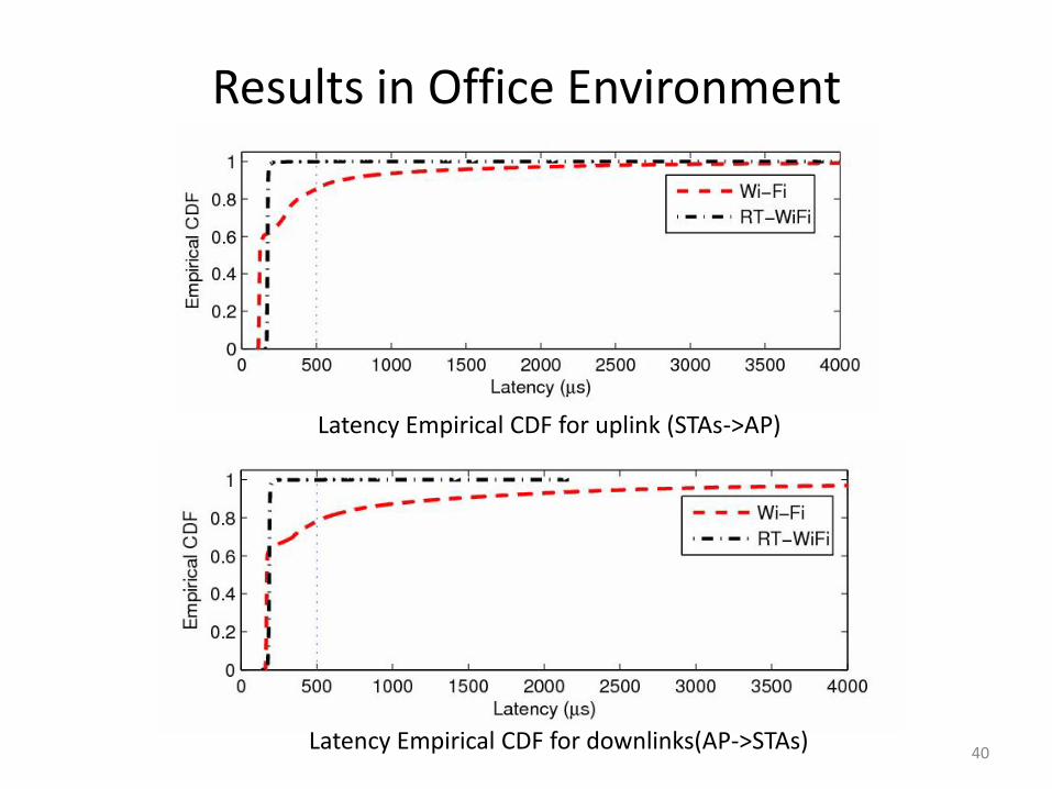
Results in Office Environment
Latency Empirical CDF for uplink (STAs->AP)
Latency Empirical CDF for downlinks(AP->STAs)
Simulation of a Wireless Control System
• After integrate RT-WiFi with smart shoes, we collect traces of each sensor data packets to get the network dynamics.
• Then, we run simulation of the controller based on the traces to evaluate the performance of the wireless control system.
• A proportional-derivative (PD) controller was implemented in the simulation to track a sinusoidal signal with unit magnitude.
• Simulation were conducted with different controller gains and reference frequencies.
41
42
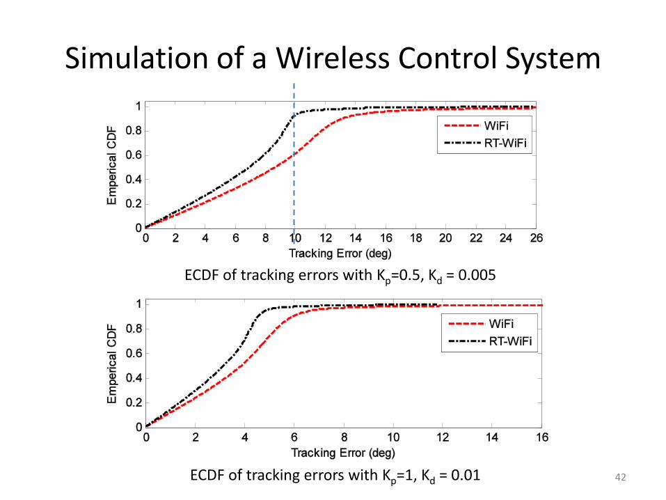
Simulation of a Wireless Control System
ECDF of tracking errors with Kp=0.5, Kd = 0.005
ECDF of tracking errors with Kp=1, Kd = 0.01
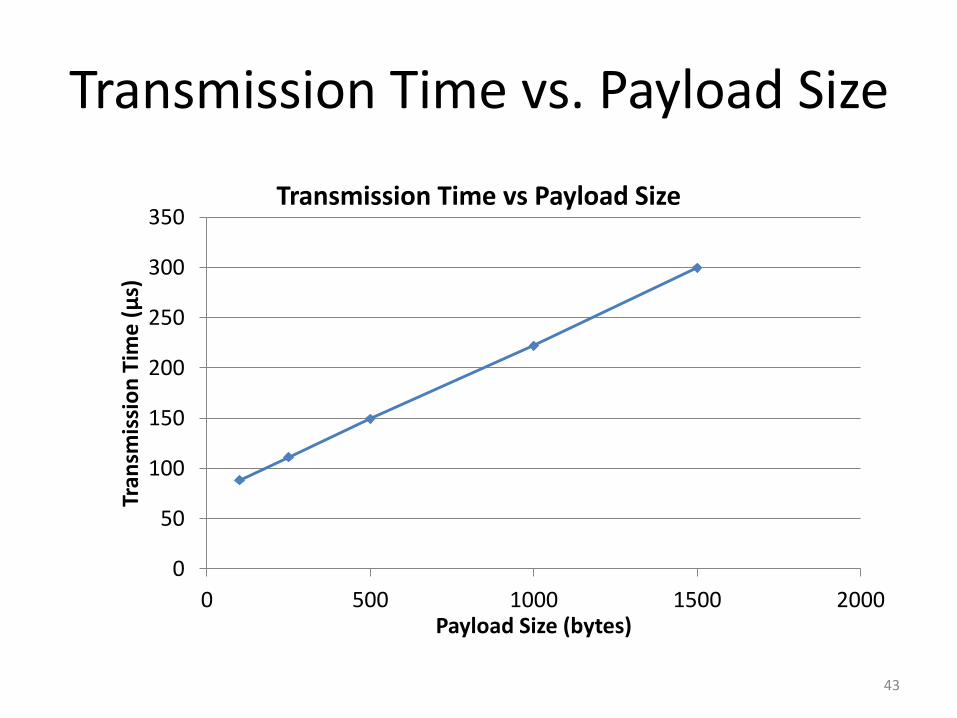
Transmission Time vs. Payload Size
43
0
50
100
150
200
250
300
350
0 500 1000 1500 2000
Tran
smis
sio
n T
ime
(μ
s)
Payload Size (bytes)
Transmission Time vs Payload Size
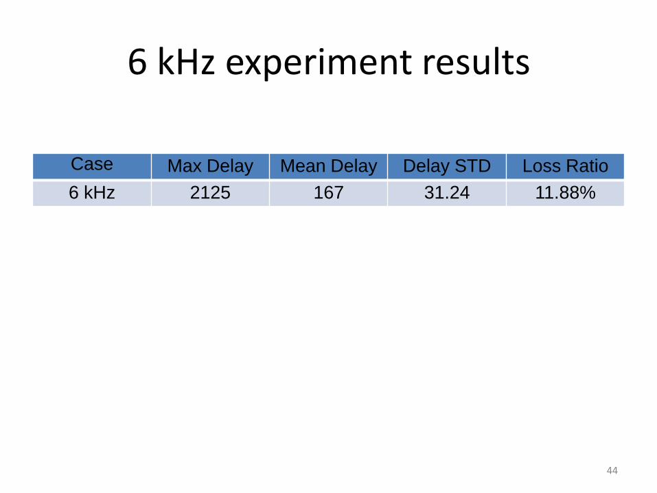
6 kHz experiment results
Case Max Delay Mean Delay Delay STD Loss Ratio
6 kHz 2125 167 31.24 11.88%
44
Recommended