
Run-on and Run-off Control System Plan
H.W. Pirkey Power Plant Stack-Out Pad Hallsville, Harrison County, Texas
October 14, 2016
Akron Project Number: 237P-002
Prepared for: American Electric Power
1 Riverside Plaza Columbus, Ohio 43215
Prepared by: Akron Consulting, LLC
431 N Center St. Longview, Texas 75601
TBPE Firm # 14014
Run-on and Run-off Control System Plan H.W. Pirkey Power Plant Stack-Out Pad, Hallsville, Texas American Electric Power
Page 2
Akron 237P-002 / October, 2016
Table of Contents
Table of Contents ...................................................................................................................... 2 1.0 INTRODUCTION .............................................................................................................. 3 2.0 RUN-ON CONTROLS ........................................................................................................ 3
2.1 Run-On Controls Outside the Stack-Out Pad ........................................................................... 3 2.1.1 Diversion Dikes and Berms ................................................................................................ 3 2.1.2 Stormwater Perimeter Ditches ............................................................................................ 3
3.0 RUN-OFF CONTROLS ....................................................................................................... 4 3.1 Perimeter HDPE Lined Berm .................................................................................................. 4 3.2 Perimeter Ditches ................................................................................................................. 4 3.3 Surge Pond .......................................................................................................................... 4
4.0 PLAN REVIEW AND CHANGES IN FACILITY OPERATION ................................................ 4 5.0 PROFESSIONAL ENGINEER CERTIFICATION .................................................................. 5
APPENDIX A: Figures and Calculations
APPENDIX B: Run-On and Run-Off Plan Review Log
APPENDIX C: Professional Engineer Certification
Run-on and Run-off Control System Plan H.W. Pirkey Power Plant Stack-Out Pad, Hallsville, Texas American Electric Power
Page 3
Akron 237P-002 / October, 2016
1.0 INTRODUCTION
Federal Regulation Title 40, Part 257.81 requires the owner or operator of an existing or new CCR landfill or any lateral expansion of an existing CCR landfill to comply with the following:
1. A run-on control system to prevent flow onto the active portion of the CCR unit during the peak discharge from a 24-hour, 25-year storm.
2. A run-off control system from the active portion of the CCR unit to collect and control at least the water volume resulting from a 24-hour, 25-year storm.
3. Run-off from the active portion of the CCR unit must be handled in accordance with the surface water requirements under §257.3-3
4. Prepare initial and periodic run-on and run-off control system plans for the CCR unit according to the following timeframes:
a. For existing CCR landfills, the owner or operator of the CCR unit must prepare the initial run-on and run-off control system plan no later than October 17, 2016.
b. The owner or operator of the CCR unit must prepare periodic run-on and run-off control system plans every five (5) years.
5. Obtain a certification from a qualified professional engineer stating that the initial and periodic run-on and run-off control system plans meet the requirements of this section.
6. Comply with the recordkeeping requirements specified in §257.105(g), the notification requirements specified in §257.106(g), and the internet requirements specified in §257.107(g).
This Run-on and Run-off Control System Plan presents the regulatory-required materials as noted above. It is prepared for the stack-out pad at AEP’s H.W. Pirkey Power Plant in Hallsville, Texas.
2.0 RUN-ON CONTROLS
The purpose of run-on controls is to prevent storm water from entering into the stack-out pad from a 24-hour, 25-year storm.
2.1 Run-On Controls Outside the Stack-Out Pad
2.1.1 Diversion Dikes and Berms
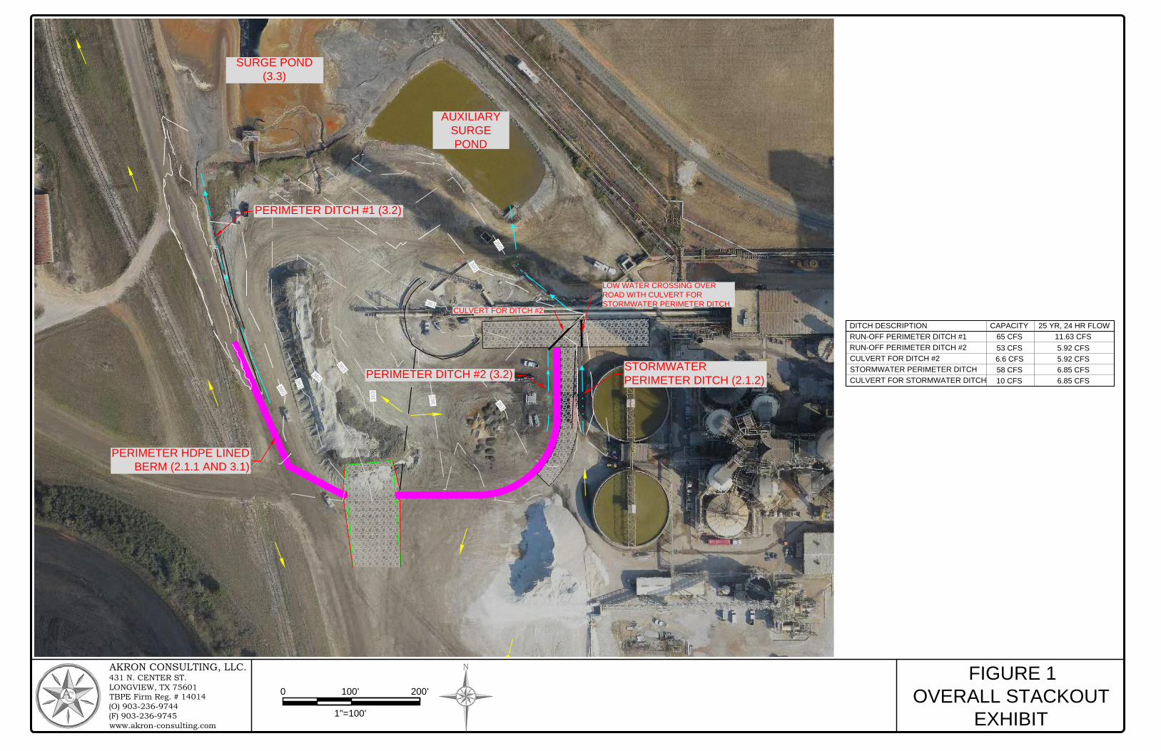
An HDPE lined berm is proposed to be constructed around the southern, western, and eastern sides of the stack-out pad. This berm will provide a barrier that will not allow stormwater from the plant to enter the stack-out pad.
2.1.2 Stormwater Perimeter Ditches
An existing stormwater ditch to the east of the stack-out pad directs run-on water away from the proposed berm to the Auxiliary Surge Pond. See Appendix A for calculations. Stormwater to the south flows away from the berm to the south. Stormwater on the west side of the stack-out pad flows to the north.
Run-on and Run-off Control System Plan H.W. Pirkey Power Plant Stack-Out Pad, Hallsville, Texas American Electric Power
Page 4
Akron 237P-002 / October, 2016
3.0 RUN-OFF CONTROLS
The run-off control system prevents flow (contact water) from leaving the stack-out pad during a 24-hour, 25-year storm. Run-off control consists of the following aspects:
• Perimeter HDPE lined berm • Perimeter Ditches • Surge Pond
Stormwater from the stack-out pad travels to the surge pond via perimeter ditches. Perimeter HDPE lined berms help to ensure that stormwater is directed to these ditches and does not leave the stack-out pad. The surge pond accepts all stormwater from the stack-out pad, and water from the surge pond is utilized by the power plant in the FGD system.
3.1 Perimeter HDPE Lined Berm The entire stack-out pad will be surrounded on three sides by an HDPE lined berm. The berm will be 1.5’ tall, with a 3’ top width. Not only does the berm prevent run-on from entering the stack-out pad, it forces stormwater inside the stack-out pad to enter perimeter ditches that carry contact water to the surge pond. The design calculations for the Perimeter HDPE lined berms are a function of the perimeter ditches, and calculations for the perimeter ditches are provided in Figure 1.
3.2 Perimeter Ditches Perimeter ditches inside the stack-out pad will be constructed to transport contact water to the surge pond. One perimeter ditch on the west side of the stack-out pad discharges directly into the surge pond, while another perimeter ditch on the east side discharges into a culvert which discharges into a ditch that enters the auxiliary surge pond. The stack-out pad is graded to divert stormwater to these ditches. Design calculations for the perimeter ditches are provided in the Figure 1.
3.3 Surge Pond All stormwater from the stack-out pad enters the surge pond. Water in the surge pond is utilized by the power plant in the FGD system.
4.0 PLAN REVIEW AND CHANGES IN FACILITY OPERATION
Stack-out Pad Owner and/or Operator will review and evaluate this Plan every five (5) years from initial plan preparation and when there are changes in the facility design, construction, operation, or maintenance that materially affect the facility’s potential for run-on and run-off control. Amendments to the Plan made to address changes of this nature are referred to as technical or major amendments, and must be certified by a P.E. Non-technical amendments can be performed by the facility owner and/or operator.
Technical and administrative amendments to the Plan will be documented on the Plan Review Log. Owner/Operator will make the necessary revisions to the Plan as soon as possible, but no later than six months after the change occurs. The Plan must be implemented as soon as possible following a technical amendment, but no later than six months from the date of the amendment. The Designated Person is responsible for initiating and coordinating revisions to the SPCC Plan.
Scheduled reviews and Plan amendments will be recorded in the Plan Review Log provided in Appendix 2. The log will be completed even if no amendment is made to the Plan as a result of the review.

Run-on and Run-off Control System Plan H.W. Pirkey Power Plant Stack-Out Pad, Hallsville, Texas American Electric Power
Page 5
Akron 237P-002 / October, 2016
5.0 PROFESSIONAL ENGINEER CERTIFICATION
This original Plan, and all subsequent reviews and amended plans, must obtain certification from a qualified PE stating that the initial and subsequent run-on and run-off control system plans meet the requirements of 40 CFR 257. This certification in no way relieves the owner or operator of the facility of his/her duty to fully implement this Plan. The Professional Engineer Certification page is provided in Appendix C.

APPENDIX A: Figures and Calculations
►
►
►
►
►
►
3
6
0
3
6
1
3
6
2
3
6
3
3
6
1
362
363
3
6
0
3
5
9
3
6
1
PERIMETER HDPE LINED
BERM (2.1.1 AND 3.1)
PERIMETER DITCH #1 (3.2)
SURGE POND
(3.3)
AUXILIARY
SURGE
POND
STORMWATER
PERIMETER DITCH (2.1.2)
PERIMETER DITCH #2 (3.2)
LOW WATER CROSSING OVER
ROAD WITH CULVERT FOR
STORMWATER PERIMETER DITCH
CULVERT FOR DITCH #2
AKRON CONSULTING, LLC.431 N. CENTER ST.LONGVIEW, TX 75601TBPE Firm Reg. # 14014(O) 903-236-9744(F) 903-236-9745www.akron-consulting.com
FIGURE 1
OVERALL STACKOUT
EXHIBIT
1"=100'
0 100' 200'
N
CULVERT FOR DITCH #2
RUN-OFF PERIMETER DITCH #1
RUN-OFF PERIMETER DITCH #2
65 CFS
53 CFS
6.6 CFS
CAPACITYDITCH DESCRIPTION
11.63 CFS
5.92 CFS
5.92 CFS
25 YR, 24 HR FLOW
STORMWATER PERIMETER DITCH
CULVERT FOR STORMWATER DITCH10 CFS
58 CFS
6.85 CFS
6.85 CFS
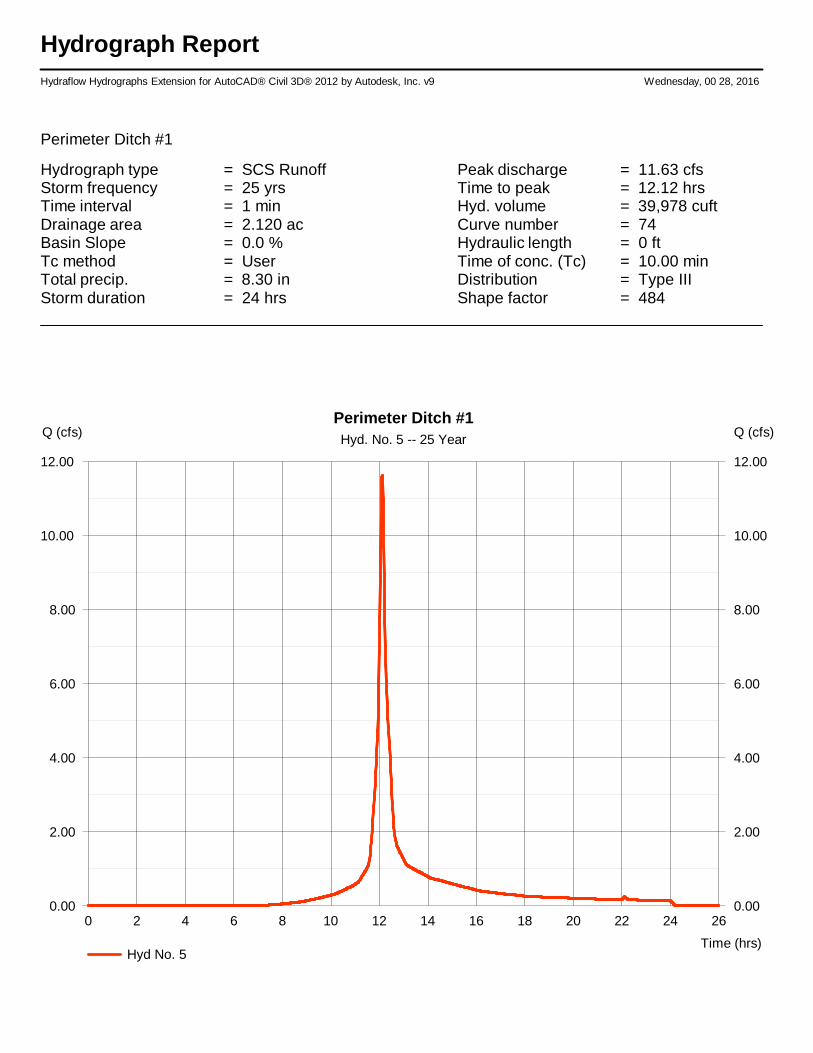
Hydrograph ReportHydraflow Hydrographs Extension for AutoCAD® Civil 3D® 2012 by Autodesk, Inc. v9 Wednesday, 00 28, 2016
Perimeter Ditch #1
Hydrograph type = SCS Runoff Peak discharge = 11.63 cfsStorm frequency = 25 yrs Time to peak = 12.12 hrsTime interval = 1 min Hyd. volume = 39,978 cuftDrainage area = 2.120 ac Curve number = 74Basin Slope = 0.0 % Hydraulic length = 0 ftTc method = User Time of conc. (Tc) = 10.00 minTotal precip. = 8.30 in Distribution = Type IIIStorm duration = 24 hrs Shape factor = 484
0 2 4 6 8 10 12 14 16 18 20 22 24 26
Q (cfs)
0.00 0.00
2.00 2.00
4.00 4.00
6.00 6.00
8.00 8.00
10.00 10.00
12.00 12.00
Q (cfs)
Time (hrs)
Perimeter Ditch #1Hyd. No. 5 -- 25 Year
Hyd No. 5
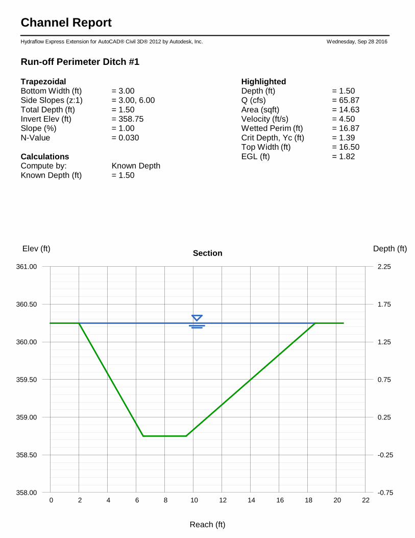
Channel ReportHydraflow Express Extension for AutoCAD® Civil 3D® 2012 by Autodesk, Inc. Wednesday, Sep 28 2016
Run-off Perimeter Ditch #1
TrapezoidalBottom Width (ft) = 3.00Side Slopes (z:1) = 3.00, 6.00Total Depth (ft) = 1.50Invert Elev (ft) = 358.75Slope (%) = 1.00N-Value = 0.030
CalculationsCompute by: Known DepthKnown Depth (ft) = 1.50
HighlightedDepth (ft) = 1.50Q (cfs) = 65.87Area (sqft) = 14.63Velocity (ft/s) = 4.50Wetted Perim (ft) = 16.87Crit Depth, Yc (ft) = 1.39Top Width (ft) = 16.50EGL (ft) = 1.82
0 2 4 6 8 10 12 14 16 18 20 22
Elev (ft) Depth (ft)Section
358.00 -0.75
358.50 -0.25
359.00 0.25
359.50 0.75
360.00 1.25
360.50 1.75
361.00 2.25
Reach (ft)
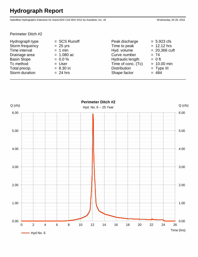
Hydrograph ReportHydraflow Hydrographs Extension for AutoCAD® Civil 3D® 2012 by Autodesk, Inc. v9 Wednesday, 00 28, 2016
Perimeter Ditch #2
Hydrograph type = SCS Runoff Peak discharge = 5.923 cfsStorm frequency = 25 yrs Time to peak = 12.12 hrsTime interval = 1 min Hyd. volume = 20,366 cuftDrainage area = 1.080 ac Curve number = 74Basin Slope = 0.0 % Hydraulic length = 0 ftTc method = User Time of conc. (Tc) = 10.00 minTotal precip. = 8.30 in Distribution = Type IIIStorm duration = 24 hrs Shape factor = 484
0 2 4 6 8 10 12 14 16 18 20 22 24 26
Q (cfs)
0.00 0.00
1.00 1.00
2.00 2.00
3.00 3.00
4.00 4.00
5.00 5.00
6.00 6.00
Q (cfs)
Time (hrs)
Perimeter Ditch #2Hyd. No. 6 -- 25 Year
Hyd No. 6
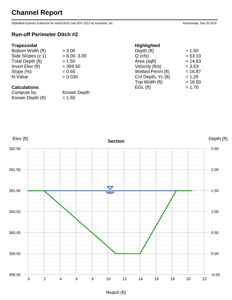
Channel ReportHydraflow Express Extension for AutoCAD® Civil 3D® 2012 by Autodesk, Inc. Wednesday, Sep 28 2016
Run-off Perimeter Ditch #2
TrapezoidalBottom Width (ft) = 3.00Side Slopes (z:1) = 6.00, 3.00Total Depth (ft) = 1.50Invert Elev (ft) = 359.50Slope (%) = 0.65N-Value = 0.030
CalculationsCompute by: Known DepthKnown Depth (ft) = 1.50
HighlightedDepth (ft) = 1.50Q (cfs) = 53.10Area (sqft) = 14.63Velocity (ft/s) = 3.63Wetted Perim (ft) = 16.87Crit Depth, Yc (ft) = 1.25Top Width (ft) = 16.50EGL (ft) = 1.70
0 2 4 6 8 10 12 14 16 18 20 22
Elev (ft) Depth (ft)Section
359.00 -0.50
359.50 0.00
360.00 0.50
360.50 1.00
361.00 1.50
361.50 2.00
362.00 2.50
Reach (ft)
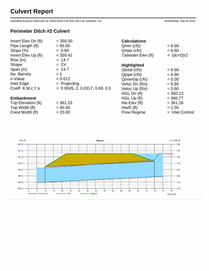
Culvert ReportHydraflow Express Extension for AutoCAD® Civil 3D® 2012 by Autodesk, Inc. Wednesday, Sep 28 2016
Perimeter Ditch #2 Culvert
Invert Elev Dn (ft) = 359.00Pipe Length (ft) = 65.00Slope (%) = 0.65Invert Elev Up (ft) = 359.42Rise (in) = 14.7Shape = CirSpan (in) = 14.7No. Barrels = 1n-Value = 0.012Inlet Edge = ProjectingCoeff. K,M,c,Y,k = 0.0045, 2, 0.0317, 0.69, 0.5
EmbankmentTop Elevation (ft) = 361.25Top Width (ft) = 40.00Crest Width (ft) = 20.00
CalculationsQmin (cfs) = 6.60Qmax (cfs) = 6.60Tailwater Elev (ft) = (dc+D)/2
HighlightedQtotal (cfs) = 6.60Qpipe (cfs) = 6.60Qovertop (cfs) = 0.00Veloc Dn (ft/s) = 5.80Veloc Up (ft/s) = 5.60HGL Dn (ft) = 360.13HGL Up (ft) = 360.77Hw Elev (ft) = 361.26Hw/D (ft) = 1.50Flow Regime = Inlet Control
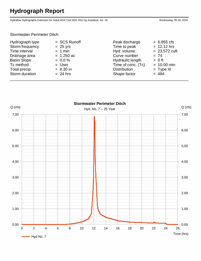
Hydrograph ReportHydraflow Hydrographs Extension for AutoCAD® Civil 3D® 2012 by Autodesk, Inc. v9 Wednesday, 00 28, 2016
Stormwater Perimeter Ditch
Hydrograph type = SCS Runoff Peak discharge = 6.855 cfsStorm frequency = 25 yrs Time to peak = 12.12 hrsTime interval = 1 min Hyd. volume = 23,572 cuftDrainage area = 1.250 ac Curve number = 74Basin Slope = 0.0 % Hydraulic length = 0 ftTc method = User Time of conc. (Tc) = 10.00 minTotal precip. = 8.30 in Distribution = Type IIIStorm duration = 24 hrs Shape factor = 484
0 2 4 6 8 10 12 14 16 18 20 22 24 26
Q (cfs)
0.00 0.00
1.00 1.00
2.00 2.00
3.00 3.00
4.00 4.00
5.00 5.00
6.00 6.00
7.00 7.00
Q (cfs)
Time (hrs)
Stormwater Perimeter DitchHyd. No. 7 -- 25 Year
Hyd No. 7
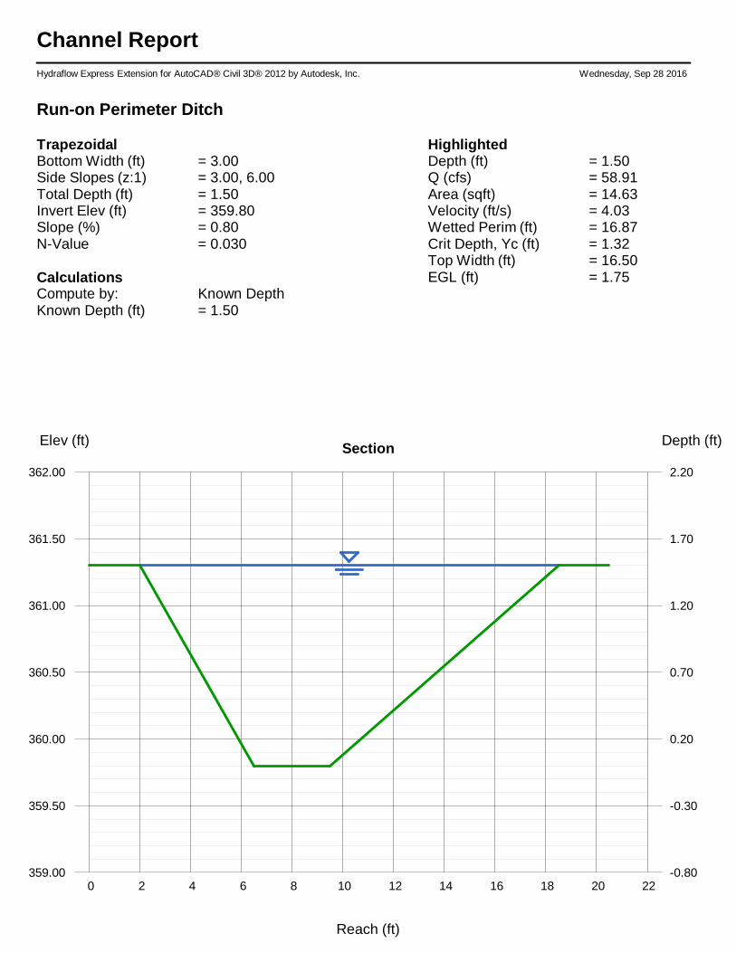
Channel ReportHydraflow Express Extension for AutoCAD® Civil 3D® 2012 by Autodesk, Inc. Wednesday, Sep 28 2016
Run-on Perimeter Ditch
TrapezoidalBottom Width (ft) = 3.00Side Slopes (z:1) = 3.00, 6.00Total Depth (ft) = 1.50Invert Elev (ft) = 359.80Slope (%) = 0.80N-Value = 0.030
CalculationsCompute by: Known DepthKnown Depth (ft) = 1.50
HighlightedDepth (ft) = 1.50Q (cfs) = 58.91Area (sqft) = 14.63Velocity (ft/s) = 4.03Wetted Perim (ft) = 16.87Crit Depth, Yc (ft) = 1.32Top Width (ft) = 16.50EGL (ft) = 1.75
0 2 4 6 8 10 12 14 16 18 20 22
Elev (ft) Depth (ft)Section
359.00 -0.80
359.50 -0.30
360.00 0.20
360.50 0.70
361.00 1.20
361.50 1.70
362.00 2.20
Reach (ft)
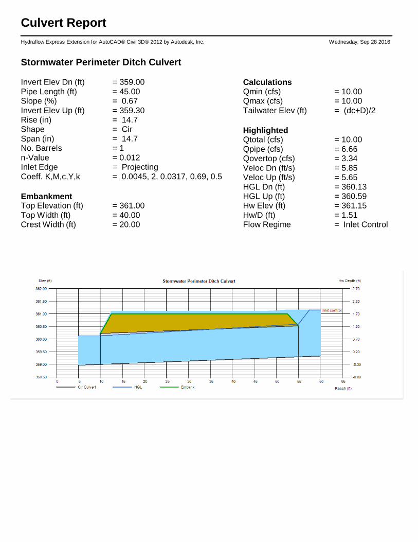
Culvert ReportHydraflow Express Extension for AutoCAD® Civil 3D® 2012 by Autodesk, Inc. Wednesday, Sep 28 2016
Stormwater Perimeter Ditch Culvert
Invert Elev Dn (ft) = 359.00Pipe Length (ft) = 45.00Slope (%) = 0.67Invert Elev Up (ft) = 359.30Rise (in) = 14.7Shape = CirSpan (in) = 14.7No. Barrels = 1n-Value = 0.012Inlet Edge = ProjectingCoeff. K,M,c,Y,k = 0.0045, 2, 0.0317, 0.69, 0.5
EmbankmentTop Elevation (ft) = 361.00Top Width (ft) = 40.00Crest Width (ft) = 20.00
CalculationsQmin (cfs) = 10.00Qmax (cfs) = 10.00Tailwater Elev (ft) = (dc+D)/2
HighlightedQtotal (cfs) = 10.00Qpipe (cfs) = 6.66Qovertop (cfs) = 3.34Veloc Dn (ft/s) = 5.85Veloc Up (ft/s) = 5.65HGL Dn (ft) = 360.13HGL Up (ft) = 360.59Hw Elev (ft) = 361.15Hw/D (ft) = 1.51Flow Regime = Inlet Control

APPENDIX B: Run-On and Run-Off Plan
Review Log

Plan Review and Changes in Facility Configuration Scheduled reviews and Plan amendments shall be recorded in the Plan Review Log below. This log must be completed even if no amendment is made to the Plan as a result of the review.
By Date Amendment Description
P.E. Certification Required?
P.E. Name
Licensing State:
Registration No.

APPENDIX C: Professional Engineer Certification

Professional Engineer Certification
The Run-on Run-off System Control Plan for the H.W. Pirkey Power Plant Stack-Out Pad was prepared by Akron Consulting, LLC (Akron). This Certification/Statement of Professional Opinion is limited to the information available to Akron at the time the Plan was written. On the basis of and subject to the foregoing, it is my professional opinion as a Professional Engineer licensed in the State of Texas, that the Plan has been prepared in accordance with good and accepted engineering practices as exercised by other engineers practicing in the same discipline(s), under similar circumstances at the time and in the same locale. It is my professional opinion that the Plan was prepared consistent with the requirements of the United States Environmental Protection Agency’s “Standards for the Disposal of Coal Combustion Residuals in Landfills and Surface Impoundments,” published in the Federal Register on April 17, 2015 with an effective date of October 19, 2015 and meets the requirements of Part 257.81.
The use of the words “certification” and/or “certify” in this document shall be interpreted and construed as a Statement of Professional Opinion, and is not and shall not be interpreted or construed as a guarantee, warranty or legal opinion. This certification in no way relieves the Owner or Operator of the facility of his/her duty to fully implement this Plan.
Engineer: ________________________________
Registration Number: ________________________________
State: ________________________________
Date: ________________________________
P.E. certification is required for the original Plan and Plan reviews and amendments.
Recommended