8/8/2019 S-55B Press Kit
http://slidepdf.com/reader/full/s-55b-press-kit 1/14
8/8/2019 S-55B Press Kit
http://slidepdf.com/reader/full/s-55b-press-kit 2/14
AlvnLAW -
Space scientists have made some theoretical estimates of the
penetration capabilities of micrometeoroids, but their views
vary widely. Spacecraft designers, however, must have accurate know-
ledge of the resistance to penetration of materials,and to fulfill
that need NASA developed the S-55 series of satellites.
The launch will be third in the series. The first attempt, on
June 30, 1961, failed when the third stage of the launch vehicle did
not ignite. The second attempt placed S-55A in orbit on August 25,
1961, as Explorer XIII. Only limited information came from Explorer
XIII because it reentered after three days in orbit. Experimenters
hope to achieve for S-55B an orbit lifetime up to three years with
useful data to be gathered for about one year.
The cylindrical satellite is 24 inches in diameter and 76 inches
long. It is built around the Altair motor case which is Scout's
fourth stage and which will go into orbit as an integral part of the
assembly. Total weight in orbit will be 222 pounds. A thin heat
shield protecting the satellite during launch will be jettisoned in
space, exposing five types of sensitive detecting instruments to im-
pacts by high velocity particles of matter.
S-55B will be launched in a southeasterly direction from Wallops
Island, with injection into orbit occurring east of Puerto Rico some
1571 statute miles down range 11.54 minutes after launch.
8/8/2019 S-55B Press Kit
http://slidepdf.com/reader/full/s-55b-press-kit 3/14
-3-
The elliptical near-Earth orbit is planned to have an initial
perigee of 453 statute miles and an apogee of 661 statute miles.
Initial apogee will occur over the Indian Ocean just west of Aus-
tralia. Initial orbital period is planned for 102 minutes. The
satellite is programmed to be travelling at 16,955 miles per hour
at injection and at perigee. Its speed at apogee will be approx-
imately 16,191 miles per hour.
The belt covered by the initial orbits will extend about 51
degrees North and South of the equator, passing over the latitude
of London, England, at the northernmost point and over Cape Horn
at the most southerly,
( SCIENTIFIC OBJECTIVES
Three primary objectives have been established for the flight:
1. Direct measurement of the micrometeoroid puncture hazard
to structural skin samples,
2. Measurements of particles possessing different amounts
of momentum.
3. Comparing the performance of protected and unprotected so-
lar cells in space.
THE MICROMETEOROID SATELLITE (S-55B)
The world of science is indebted to United States satellites
for most of its current knowledge of micrometeoroids.
8/8/2019 S-55B Press Kit
http://slidepdf.com/reader/full/s-55b-press-kit 4/14
-4-
Explorer 10 Vanguard II10 Explorer VII and Explorer VIII are
among those which made significant measurements including discov-
eries that there are showers of this cosmic dust. Meteors of vari-
ous sizes intersect the earth's orbit0 sporadically and in showers
traveling at extremely high velocities0
Meteoroids are material in space, composed of iron0 silicates
and other substances. Some are derived from the asteroids (possibly
the remains of an exploded planet) which revolve around the sun be-
tween Mars and Jupiter. Those which are in elliptical orbits per-
iodically cross the earth.'s path, and impact on the earth or moon.
Comets, composed of material at cryogenic temperatures, which re -
volve in the outermost regions of our solar system, may be pulled
into eccentric orbit, melt, decay, and form comet tails as they
enter regions nearer the sun0
Meteoroids usually burn (become meteors) as they enter the at-
mosphere 0 Those which reach the earth are called meteorites. It is
believed by many scientists that several thousand tons of minute
meteorites (called micrometeorites) may settle on the earth in a
single day.
These small particles may strike a satellite at velocities
ranging from 7 miles per second to 45 miles per second.
8/8/2019 S-55B Press Kit
http://slidepdf.com/reader/full/s-55b-press-kit 5/14
-5-
More data on micrometeoroids will lead scientists closer to
knowledge of the universe's constituency and origin since stars,
comets, and planets may have been formed by the conglomeration of
interstellarmaterial0
The S-55, consisting entirely of micrometeoroid experiments
about its sizable structure, should record impacts of larger sizes
of micrometeoroids than previous satellites, It is designed to
yield as much data as possible during its useful lifetime.
These data are vitally needed by engineers who will design
future space flight systems. They need to know more about micro-
meteoroids in order to ensure the safety of manned spacecraft des-
tined fo r long missions and to design such systems as the huge rad-
iators which will be needed on electric and ion engines, powered by
nuclear reactors,
The micrometeoroid satellite experiment is a cooperative effort
of three NASA research centers, including the Langley Research Cen-
ter, Hamptono Virginia; the Lewis Research Center, Cleveland, Ohiog
and the Goddard Space Flight Center, Greenbelt, Mary'and. Langley
has the responsibility for payload integration as well as the over-
all satellite system. Langley designed the impact detecting trans-
ducers fo r determining micrometeoroid flux rates,
1~-
8/8/2019 S-55B Press Kit
http://slidepdf.com/reader/full/s-55b-press-kit 6/14
The five micrometeoroid detectors in the satellite will include
pressurized cells, foil gages, and wire grids, providing a total of
24¼ square feet of area exposed to the penetration hazard; and cad-
mium-sulfide cells, and impact sensors, which will have a combined
total of 4 square feet exposed for impact detection. Five test
groups of window-like silicon solar cells on the nose of the satel-
lite will determine what protection solar cells in future space ex-
periments will require. Five cells are shingled for each group:
one group will be unprotected, three groups will have 6-mil glass
slides covering the sensitive area, and one group will have a three
sixteenths of an inch quartz window protecting them- A series of
temperature measurements at selected places throughout the satellite
will give additional data, A telemeter system with erectable antennas
will be located in the nose section to transmit data to ground re-
ceiving stations.
Each of the sensors installed in the satellite is capable2 of
producing a measurable electrical signal that can be stored and sub-
sequently telemetered from the orbiting payload to the Minitrack
Receiving Station Network of the Goddard Space Flight Center. The
following is a description of the five micrometeoroid detectors in-
stalled in the satellite:
8/8/2019 S-55B Press Kit
http://slidepdf.com/reader/full/s-55b-press-kit 7/14
-7-
Pressurized cells: These beryllium copper detectors, the primary
sensors of the experiment, include 160 half cylinders ranging in
thickness from one-thousandth to five-thousandths of an inch, The
2-inch-wide flat area of each of the 74-in~ch-long half cylinders is
mounted in five rows of 32 cells each around the circular exterior
of the Altair rocket motor, leaving the can-like cylindrical portion
exposed to micrometeoroids. The pressurized cells occupy about a
38-inch-long section of peripheral space in the center of the satel-
lite. The exposed cells will be pressurized with helium so that a
puncture by a micrometeoroid will allow pressure to leak out. By
means of a pressure-activated switch in the end of each cello the
pressure loss will be detected and telemetered at the proper time
to ground receiving stations. The penetration area of the 160 cells
to be exposed to micrometeoroids totals about 17¼ square feet0 The
pressurized cell detector system was designed and fabricated by
Langley to provide information on the ability of certain thicknesses
of metal to resist penetration by micrometeoroids 0
Foil gages: Sixty foil gage detectors, each in the shape of
an equilateral triangle with a 4.57 inch base, are installed around
the forward useable half of the fourth-stage launch vehicle support
structure. They were conceived and developed by the Lewis Research
Center and built by the Buckbee Mears Company,
8/8/2019 S-55B Press Kit
http://slidepdf.com/reader/full/s-55b-press-kit 8/14
Each detector c,-i-sists of z~.circu.it obt-ri3.ea by -~n ~etc~To
ical depo,_:itio:n proce..,is, about 9(' miicroinchas thicAk attached to one-
mil :ylz~r and mc.,urte~~d on the underside, of 304-stainless ste;1 skin
samples -- with 24 of the skiLn s:;mples 1being 1-mril t~hickX, and 4r of
6-mil thiclItness. lvicrometeoroids which penetrate tSh~e ~-tainless :~
skin samnples and brealk the foil circuits will cause a chl-ncj.(', in th c
resistance level in th e el1ectronic circuit -- thus reco-iding - Esi~c
inform-tion that can be I.-.ter telemretered to earth, Th~rough the us~
of two thictknesses of stainleSs steel, information will lie obt,-,n-.ine"
on th e micrometeoroid penetration hazard. Tiotal surface exposed L-0
nticromneteoroids in this eXperiment is about 3 3/41 square feet,
.ire Crids: These detectors, developed by Goddiard space hi~
Center, are simtilar to sensors flown on previous satellites. Th'le .'6
detectors consist of a winding of f,.ne copper wire mounted to 1.:5
by 7 inch rectangular melamine cards, Fourteen of the cards will be
wound with 2-mil wire ar ' 32 cards with 3-mi2. wires, providing a total).
expor.ed area of 3'i square feet to penetration by micrometeoroids.
.i-s sp;we particles sttike th e grids and break th e wound wire at --1Y
location, th e resultant change rin resistance recoided for subseauent,
telemeter tran'smissiori to th e ground w2.1 Live scientis ts infoi-tatiofl
on the peiiet,:ation haazazd,The wire grids occupy the aft porti~onl of
the re'Aaining useabl.e h~.lf of the fourth-stage L~unch vehicle suPPOMt
structure.
8/8/2019 S-55B Press Kit
http://slidepdf.com/reader/full/s-55b-press-kit 9/14
Cadmium-sulfide cells: Two of these detectors, also developed by
the Goddard Space Flight Center, will be mounted in the nose cone
of the satellite about 180 degrees apart. Each detector consists
of a cadmium-sulfide cell mounted in an aluminized glass flask. The
six square inches of exposed surface provided by the two detectors
aze covered with a sheet of quarter-mil Mylar coated with evaporated
aluminum on both 5ides. In flight, extremely small particles strik-
ens the ultra-sensitive detector will penetrate the Mylar film and
allow light to focus ua the cadmium-sulfide cell0 changing its re-
sisikince, and permitting it to record information on the size of
impacting micrometeoroids.
Impact detectors: Piezoelectric crystal impact detecting rrans-
ducers, accoustica.i.ly decoupled from the satellite structure, are
mounted on sounding boards located on the nose cone, Some are mounted
on the pressurized cell area around the center of the satellite, The
impact detectors are Langley experiments. They provide a total of
3 3/4 square feet of area exposed to micrometeoroids, Three ieve's
of impact detecting sensitivity will be employed: the sounding board
portion of the satellite has the capability of recognizing micromete-
orite impacts of two different velocity levels to help identity micro-
meteorite particle masses.
8/8/2019 S-55B Press Kit
http://slidepdf.com/reader/full/s-55b-press-kit 10/14
- 10 -
Correlation of the cumulative number of impacts of each momentum
Level with the number of penetrations of the various materials in the
pressure cell area may provide the possi.billty of identification of
particles massesby statistical data analysis methods. Similarly. the
pressure cell transducer portion of the satellite is sensitized to
vicrometeoroid impacts at a certa'in level. An additional expectation
from this portion of the experiment is that the lower momentum sensi-
tivtty level emj,*'.oyed may afford some correlation between this type
of experiment, and the pressurized cell experiment
The electronics which form part of the satellite payload will
perform two functions: as a radio beacon during orbital tracking;
and as experiment telemeters during the approximately one year life-
time of the scientific package. The radio beacon will be activated
to transmit until its batteries are exhausted Two separate telem-
eters -- working independently to enhance reliability -- will be
used for storing and telemetering data to be collected by the or-
biting satellite. separate solar cells and batteries wilt supply
power as well as separate electronics for handling data, The telem-
eters will be turned or . at prescribed periods by a command from the
ground and after one minute of data transmission will be turned off
by an el±ctronic internal timer until the next transmission commana
LS given. Communication with the satellite will be on two frequencies:
136.860 megacycles and 136,200 megacycles,
8/8/2019 S-55B Press Kit
http://slidepdf.com/reader/full/s-55b-press-kit 11/14
- 11-
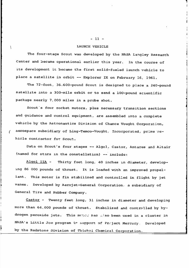
LAUNCH VEHICLE
The four-stage Scout was developed by the NASA Langley Research
Center and became operational earlier this year, In the course of
its development it became the first solid-fueled launch vehicle to
place a satellite in orbit -- Explorer IX on February 16 , 1961,
The 72-foot, 36,600-pound Scout is designed to place a 240.pound
satellite into a 300-mile orbit or to send a 100-pound scientific
package nearly 7,000 miles in a probe shot.
Scout's four rocket motors, plus necessary transition sections
and guidance and control equipment, are assembled into a complete
vehicle by the Astronautics Division of Chance Vought Corpora-tion0
' aerospace subsidiary of Ling-Temco-Vought, Incorporated prime ve-
hicle contractor for Scout.
Data on Scoutcs four stages -- Algol, Castor, Antares and Altair
(named for stars in the constellation) a- include:
AlgolhIA
-
Thirty feet long, 40 inches in diameter, develop-
ing 86 000 pounds of thrust-, It is loaded with an improved propel-
lant,, This motor is fin stabilized and controlled in flight by jet
vanes, Developed by Aerojet-General Corporation,- a subsidiary of
General Tire and Rubber Company.
Castor - Twenty feet long, 31 inches in diameter and developing
more than 64.000 pounds of thrust, Stabilized and controlled by hy-
drogen peroxide jets, This mcL. has ^<'so been used in a cluster in
NASA's Little Joe program ir support of Pr,-ject Mercury, Developed
by the Redstone Division of Thiokoi Chemical Corporation.
8/8/2019 S-55B Press Kit
http://slidepdf.com/reader/full/s-55b-press-kit 12/14
- 12
Antares - Ten feet long, 30 inches in diameter and more than
23,000 pounds of thrust. Lightweight plastic construction. Stabi-
lized and controlled by hydrogen peroxide jets. Developed by the
Allegany Ballistics Laboratory of Hercules Powder Company.
Altair - Six feet long, 18 inches in diameter and 3,000pounds
of thrust. This motor, formerly known as the X-248 and developed
for the Vanguard third stage, is spin stabilized. It is the third
stage on the Delta launch vehicle and was the first fully developed
rocket to utilize lightweight plastic construction. Also developed
by ABL.
-I
I-
8/8/2019 S-55B Press Kit
http://slidepdf.com/reader/full/s-55b-press-kit 13/14
8/8/2019 S-55B Press Kit
http://slidepdf.com/reader/full/s-55b-press-kit 14/14
PERSONNEL
The following scientists and engineers have had active
roles in the development of the S-55B and its experiments as
indicated:
LANGLEY RESEARCH CENTER
Earl Hastings, Jr., Project Manager; Hugh C. Halliday,
Project Engineer; Walt C. Long, Instrumentation Project
Engineer; John L. Patterson, Payload Power Supply; Hugh C.
Halliday and Rufus K. Dail, Payload Design; Charles A. Gurtler,
Langley pressurized cell detectors; A. G. Beswick, Langley
piezoelectric impact detectors; Lt. Col. George Rupp, Head of
Scout Project Office, launch vehicle.
GODDARD SPACE FLIGHT CENTER
Luc Secretan, Goddard detectors; John F. South, tracking.
LEWIS RESEARCH CENTER
Elmer Davison, Lewis detectors.
WALLOPS STATION
Robert T. ruffy, launch operations.
NASA HEADQUARTERS
Office of Advanced Research and Technology: C. T. D'Aiutolo,
Program Officer; Clotaire Wood, Chief of Flight Vehicle Experi-
ments; and E. 0. Pearson, Assistant Directors Office of Space
Vehicles.
Office of Tracking and Data Systems: W. E. Williams.
- END -
Recommended