S1
Electronic Supporting Information for:
Mechanically and chemically robust ZIF-8 monoliths with high
volumetric adsorption capacity
Tian Tian,a Jose Velazquez-Garcia,
a Thomas D. Bennett
b and David Fairen-Jimenez
a,*
aDepartment of Chemical Engineering & Biotechnology, University of Cambridge, Pembroke Street, Cambridge CB2
3RA, United Kingdom. Email: [email protected]; website: http://people.ds.cam.ac.uk/df334
bDepartment of Materials Science and Metallurgy, University of Cambridge, 27 Charles Babbage Road, Cambridge CB3
0FS, United Kingdom
Contents S1 Transmission Electron Microscopy (TEM) ........................................................................................................ S1
S2 X-ray Powder Diffraction ................................................................................................................................... S2
S3 N2 adsorption isotherm ....................................................................................................................................... S3
S4 Mercury porosimetry .......................................................................................................................................... S4
S5 Nanoindentation ................................................................................................................................................. S5
S6 Chemical stability ............................................................................................................................................. S13
S1 Transmission Electron Microscopy (TEM)
Fig. S1 TEM image of ZIF-8.
100 nm
Electronic Supplementary Material (ESI) for Journal of Materials Chemistry A.This journal is © The Royal Society of Chemistry 2014

S2
S2 X-ray Powder Diffraction
Fig. S2 X-ray diffraction patterns of ZIF-8 monoliths before grinding (a-c) and after grinding (d-f) compared
with the simulated pattern (g). Note that the position of the peaks and relative intensities from monolithic and
grinded samples are similar.
5 10 15 20 25 30
Inte
ns
ity (
a.u
.)
2q (o)
(g) ZIF-8
(f) ZIF-8LT
(e) ZIF-8LT-HT
(d) ZIF-8ER
(c) Monolithic ZIF-8LT
(b) Monolithic ZIF-8LT-HT
(a) Monolithic ZIF-8ER

S3
S3 N2 adsorption isotherm
Fig. S3 N2 Adsorption isotherms at 77 K for ZIF-8LT, red squares, ZIF-8HT, green triangles, ZIF-8LT-HT,
black diamonds, and ZIF-8ER, purple circles, in a semi-logarithmic (left) and linear (right) scale.
Table S1 Gravimetric and volumetric BET areas (SBET), micropore volume (W0), meso- and macropore
volume (V2), total pore volume (VTot) and bulk density (ρb) for the different ZIF-8 structures.
Material SBET W0a
V2 VTotb
ρbc
SBET(vol) W0(vol) V2(vol) VTot(vol)
m2/g cm
3/g cm
3/g cm
3/g g/cm
3 m
2/cm
3 cm
3/cm
3 cm
3/cm
3 cm
3/cm
3
ZIF-8HT 1387 0.552 0.277 0.829 0.35d
403 0.193 0.097 0.29
ZIF-8LT 1359 0.532 0.011 0.543 1.14 1594 0.606 0.013 0.619
ZIF-8LT-HT 1423 0.543 0.003 0.546 1.05 1494 0.570 0.003 0.573
ZIF-8ER 1395 0.535 0.010 0.545 1.19 1660 0.637 0.012 0.648
0
100
200
300
400
500
600
0.00 0.25 0.50 0.75 1.00
Vad
s (
cm
3/g
ST
P)
P/P0
0
100
200
300
400
500
600
1E-5 1E-4 1E-3 1E-2 1E-1 1E+0
Vad
s (
cm
3/g
ST
P)
P/P0
Theoretical single crystal capacity
Theoretical single crystal capacity
b
a
0
50
100
150
200
250
300
350
400
450
500
0.00 0.25 0.50 0.75 1.00
Vad
s (
cm
3/c
m3
ST
P)
P/P0
c
0
100
200
300
400
500
1E-5 1E-4 1E-3 1E-2 1E-1 1E+0
Vad
s (
cm
3/c
m3
ST
P)
P/P0
Theoretical single crystal capacity
d

S4
S4 Mercury porosimetry
Based on Archimedes’ method, it allows measuring the total volume including the volume of the skeleton
and the porosity of the MOF samples since mercury at ambient pressure does not penetrate any micro-,
meso- and macroporosity. Bulk densities of the samples can be calculated by dividing the mass of the sample
by the total volume. Figure S20 shows the pore size distribution of the macro- and mesoporosity of the
samples.
Fig. S4 Pore size distribution of the macro- and mesoporosity of ZIF-8LT and ZIF-8ER
0
0.001
0.002
0.003
0.004
0.005
0.006
0.007
0.008
110100100010000
dV
/dr
(cm
3/g
·nm
)
Pore size diameter (nm)
ZIF-8 LT
ZIF-8 ER

S5
S5 Nanoindentation
ZIF-8LT:
45 indents of 1000nm were performed (10 below on graph)
Fig. S5 Load-displacement data for 20 indents on ZIF-8LT, showing excellent consistency.
Fig. S6 2 Rows of 1000 nm indents made on a sample (5 x 5 mm) of ZIF-8LT.
0
1
2
3
4
5
6
7
0 500 1000 1500
Lo
ad
(m
N)
Depth into Surface (nm)
S6
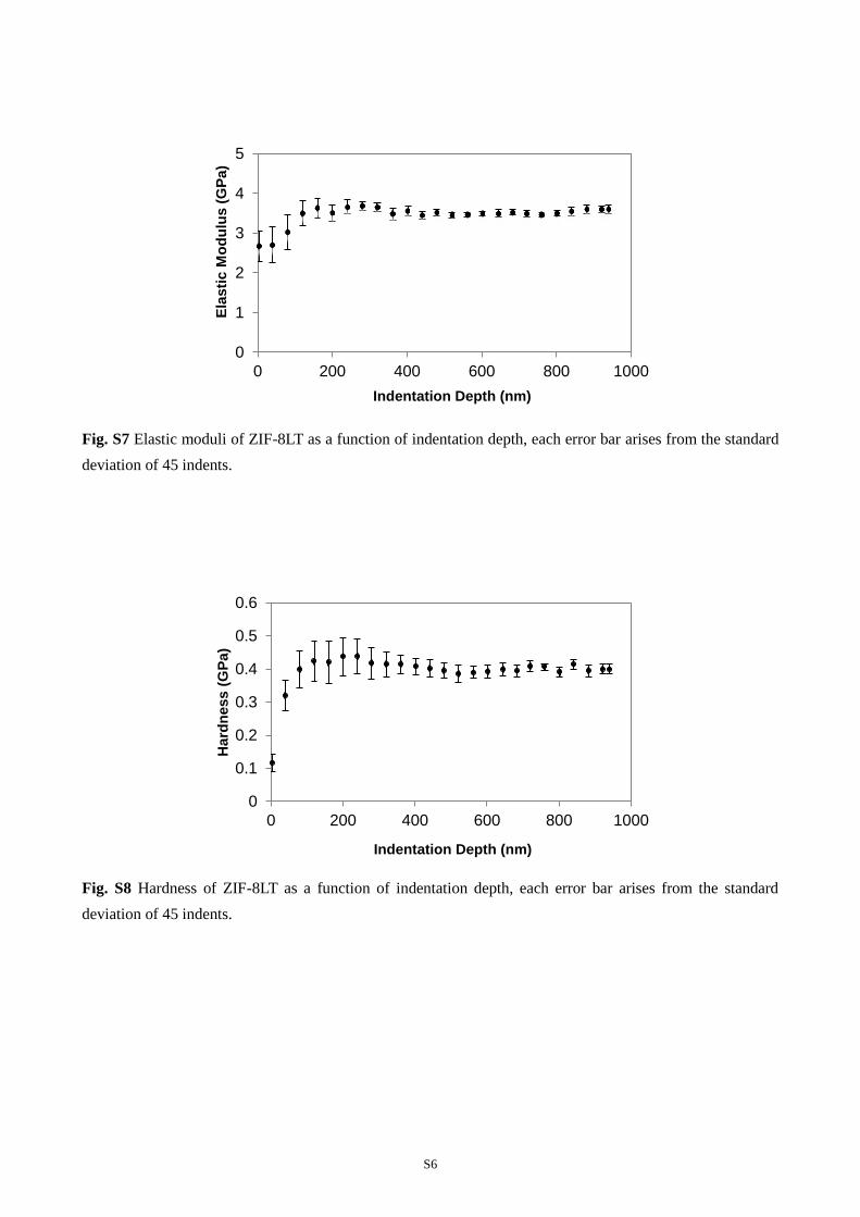
Fig. S7 Elastic moduli of ZIF-8LT as a function of indentation depth, each error bar arises from the standard
deviation of 45 indents.
Fig. S8 Hardness of ZIF-8LT as a function of indentation depth, each error bar arises from the standard
deviation of 45 indents.
0
1
2
3
4
5
0 200 400 600 800 1000
Ela
sti
c M
od
ulu
s (
GP
a)
Indentation Depth (nm)
0
0.1
0.2
0.3
0.4
0.5
0.6
0 200 400 600 800 1000
Hard
ness (
GP
a)
Indentation Depth (nm)

S7
ZIF-8LT-HT:
Fig. S9 Load-displacement data for 20 indents on ZIF-8LT-HT.
Fig. S10 2 Rows of 1000 nm indents made on a sample (5 x 5 mm) of ZIF-8LT-HT.
0
1
2
3
4
5
6
7
0 500 1000 1500
Lo
ad
(m
N)
Indentation Depth (nm)

S8
Fig. S11 Elastic moduli of ZIF-8LT-HT as a function of indentation depth, each error bar arises from the
standard deviation of 45 indents.
Fig. S12 Hardness of ZIF-8LT-HT as a function of indentation depth, each error bar arises from the standard
deviation of 45 indents.
0
1
2
3
4
5
0 200 400 600 800 1000 1200
Ela
sti
c M
od
ulu
s (
GP
a)
Indentation Depth (nm)
0
0.1
0.2
0.3
0.4
0.5
0.6
0 200 400 600 800 1000 1200
Hard
ness (
GP
a)
Indetation Depth (nm)

S9
ZIF-8ER
A) 15 indents of 1000 nm depth performed on one monolith
B) 6 indents of 3000 nm performed on a second monolith.
A) 3000nm data set:
Fig. S13 Load-displacement data for 6 indents on ZIF-8ER.
Fig. S14 Elastic moduli of ZIF-8ER as a function of indentation depth, each error bar arises from the
standard deviation of 6 indents.
0
20
40
60
80
100
0 1000 2000 3000 4000
Lo
ad
(m
N)
Indentation Depth (nm)
0
2
4
6
8
0 200 400 600 800 1000 1200
Ela
sti
c M
od
ulu
s (
GP
a)
Indentation Depth (nm)

S10
Fig. S15 Hardness of ZIF-8ER as a function of indentation depth, each error bar arises from the standard
deviation of 6 indents.
Fig. S16 1000 nm indent made on a sample (5 x 5 mm) of ZIF-8ER.
0
0.1
0.2
0.3
0.4
0.5
0.6
0.7
0 200 400 600 800 1000 1200
Hard
ness (
GP
a)
Indentation Depth (nm)

S11
B) 1000 nm data set:
Fig. S17 Load-displacement data for 15 indents on ZIF-8ER.
Fig. S18 Hardness of ZIF-8ER as a function of indentation depth, each error bar arises from the standard
deviation of 15 indents.
0
2
4
6
8
10
12
0 200 400 600 800 1000 1200
Lo
ad
(m
N)
Indentation Depth (nm)
0
0.2
0.4
0.6
0.8
0 200 400 600 800 1000
Hard
ness (
GP
a)
Indentation Depth (nm)

S12
Fig. S19 Elastic moduli of ZIF-8ER as a function of indentation depth, each error bar arises from the
standard deviation of 15 indents.
Fig. S20 2 Rows of 1000 nm indents made on a sample (5 x 5 mm) of ZIF-8ER.
0
2
4
6
8
0 200 400 600 800 1000
Ela
sti
c M
od
ulu
s (
GP
a)
Indentation Depth (nm)

S13
S6 Chemical stability
Fig. S21 PXRD patterns of ZIF-8-ER immersed in boiling water alongside a simulated pattern of ZIF-8.
5 10 15 20 25 30
Inte
ns
ity (
a.u
.)
2q (o)
ZIF-8
3 days in boiling water
5 days in boiling water
7 days in boiling water
Recommended