SAE Technical Standards Board Rules provide that: “This report is published by SAE to advance the state of technical and engineering sciences. The use of this report is entirelyvoluntary, and its applicability and suitability for any particular use, including any patent infringement arising therefrom, is the sole responsibility of the user.”
SAE reviews each technical report at least every five years at which time it may be reaffirmed, revised, or cancelled. SAE invites your written comments and suggestions.
QUESTIONS REGARDING THIS DOCUMENT: (724) 772-8512 FAX: (724) 776-0243TO PLACE A DOCUMENT ORDER; (724) 776-4970 FAX: (724) 776-0790
SAE WEB ADDRESS http://www.sae.org
Copyright 1996 Society of Automotive Engineers, Inc.All rights reserved. Printed in U.S.A.
SURFACEVEHICLE
400 Commonwealth Drive, Warrendale, PA 15096-0001STANDARD
Submitted for recognition as an American National Standard
J887REV.
MAY96
Issued 1964-07Revised 1996-05
Superseding J887 AUG87
(R) SCHOOL BUS WARNING LAMPS
1. Scope—This SAE Standard provides test procedures, requirements, and guidelines for red and yellow schoolbus warning lamps.
2. References
2.1 Applicable Publications—The following publications form a part of this specification to the extent specifiedherein. Unless otherwise specified, the latest issue of SAE publications shall apply.
2.1.1 SAE PUBLICATIONS—Available from SAE, 400 Commonwealth Drive, Warrendale, PA 15096-0001.
SAE J575—Test Methods and Equipment for Lighting Devices and Components for Use on Vehicles LessThan 2032 mm in Overall Width
SAE J576—Plastic Materials for Use in Optical Parts Such as Lenses and Reflectors of Motor VehicleLighting Devices
SAE J578—Color SpecificationSAE J602—Headlamp Aiming Device for Mechanically Aimable Headlamp UnitsSAE J759—Lighting Identification CodeSAE J760a—Dimensional Specifications for General Service Sealed Lighting UnitsSAE J1054—Warning Lamp Alternating FlashersSAE J1383—Performance Requirements for Motor Vehicle Headlamps
3. Definitions
3.1 School Bus Red Warning Lamps—School bus red warning lamps are lights alternately flashing at 1 to 2 Hzper lamp, mounted horizontally both front and rear, intended to inform other users of the highway that suchvehicle is stopped on highway to take on or discharge school children.
3.2 School Bus Yellow Warning Lamps—School bus yellow warning lamps are lights alternately flashing at 1 to2 Hz per lamp, mounted horizontally both front and rear, intended to inform other users of the highway thatsuch vehicle is about to stop to take on or discharge school children.
4. Lighting Identification Code—Lamps conforming to this document may be identified with the code W2 inaccordance with SAE J759.

SAE J887 Revised MAY96
-2-
5. Tests
5.1 SAE J575 is part of this document. The following tests are applicable with the modifications as indicated:
5.1.1 VIBRATION TEST
5.1.2 MOISTURE TEST
5.1.3 DUST TEST
5.1.4 CORROSION TEST
5.1.5 PHOTOMETRY TEST
5.1.5.1 All photometric measurements shall be made with the filament of the lamp at a distance of at least 3 mfrom the photometric screen. The lamp axis shall be taken as the horizontal line through the light sourceparallel to what would be the longitudinal axis of the vehicle, if the lamp were mounted in its normalposition on the vehicle.
5.1.5.2 The school bus warning lamp shall be operated at design voltage.
5.1.5.3 An optional alternate measure of photometric performance can be made using flash energy.
5.1.5.3.1 The device shall be allowed to operate for 15 min prior to making photometric measurements. In allinstances where a device is required to be operated during a test specified in this document, the voltageapplied to the input wires or terminals of the device shall be 12.8 V for nominal 12 V electrical systemsand 25.6 V for nominal 24 V electrical systems.
5.1.5.3.2 Photometric luminous intensity measurements (candela seconds) shall be taken as the average of tenconsecutive flash cycles. There shall be an off time before each flash of at least 50% of the total flashcycle time.
5.1.6 Warpage test on device with plastic components.
5.2 SAE J578—Color Specification is a part of this document.
5.3 Sealed Units as described in SAE J760a and SAE J1383 designed for use as school bus warning lamps, whentested without the other parts of the lamp assembly, need only be tested to 5.1.1 and 5.1.5.
6. Requirements
6.1 Performance Requirements—A device, when tested in accordance with the test procedures specified inSection 5, shall meet the following requirements. Sealed units, as described in SAE J760a and SAE J1383when tested without the other parts of the lamp assembly, need only comply with 6.1.1, 6.1.5, and 6.1.6.
6.1.1 VIBRATION—SAE J575.
6.1.2 MOISTURE—SAE J575.
6.1.3 DUST—SAE J575.
6.1.4 CORROSION—SAE J575.
6.1.5 PHOTOMETRY—SAE J575.
SAE J887 Revised MAY96
-3-
6.1.5.1 The lamp under test shall meet the photometric performance requirements contained in Table 1 and itsfootnotes. The summation of the luminous intensity measurements at the specified test points in a zoneshall be at least the value shown.
6.1.5.2 Alternate Method—The lamp under test shall meet the photometric performance requirements containedin Table 3 and its footnotes. The summation of the flash energy measurements at the specified test pointsin a zone shall be at least the value shown.
6.1.6 WARPAGE—SAE J575.
6.1.7 COLOR—The lamp shall comply with the red or yellow requirements specified in SAE J578.
6.2 Material Requirements—Any plastic materials used in optical parts shall comply with the requirements inSAE J576.
6.3 Design Requirements
6.3.1 The functional lighted lens area of a school bus warning lamp shall not be less than 120 cm2.
6.3.2 Sealed units if used shall comply dimensionally with SAE J1383 for sealed beam lamps.
6.3.3 AIMING PROVISIONS—The lamp shall be equipped with aiming pads, as described in SAE J760a or SAEJ1383 on the lens face suitable for use with mechanical headlamp aimers as described in SAE J602. Thelamp shall be designed so that with the aiming plane normal to the photometric axis, the beam shall meet thephotometric specifications of Table 1.
7. Guidelines—The mounting and use of school bus warning lamps are specified by various legal agencies. Thefollowing guidelines, if followed, will enhance performance of the system and uniformity in use throughout thevarious jurisdictional agencies. They are not part of the test provisions, specifications, requirements, orprocedures.
7.1 Photometric Design Guidelines for School Bus Warning Lamps, when tested in accordance with 5.1.5 of thisdocument, are contained in Tables 2 and 4.
7.2 The yellow lamps should be automatically deactivated and the red lamps activated when the vehicle is stoppedto take on or discharge school children.
7.3 For circuit interrupted incandescent filament devices, see SAE J1054. The “on” period of the flasher should belong enough to permit a bulb filament to approach full brightness.
7.4 There should be a visible or an audible means of giving a clear and unmistakable indication to the driver whenthe warning lamps are activated.
7.5 Front and rear warning lamps should be spaced as far apart laterally as practical with the yellow lampsmounted inboard of the red lamps. In no case should the spacing between the inboard lamps be less than1000 mm, as measured from the nearest edge of the lens.
SAE J887 Revised MAY96
-4-
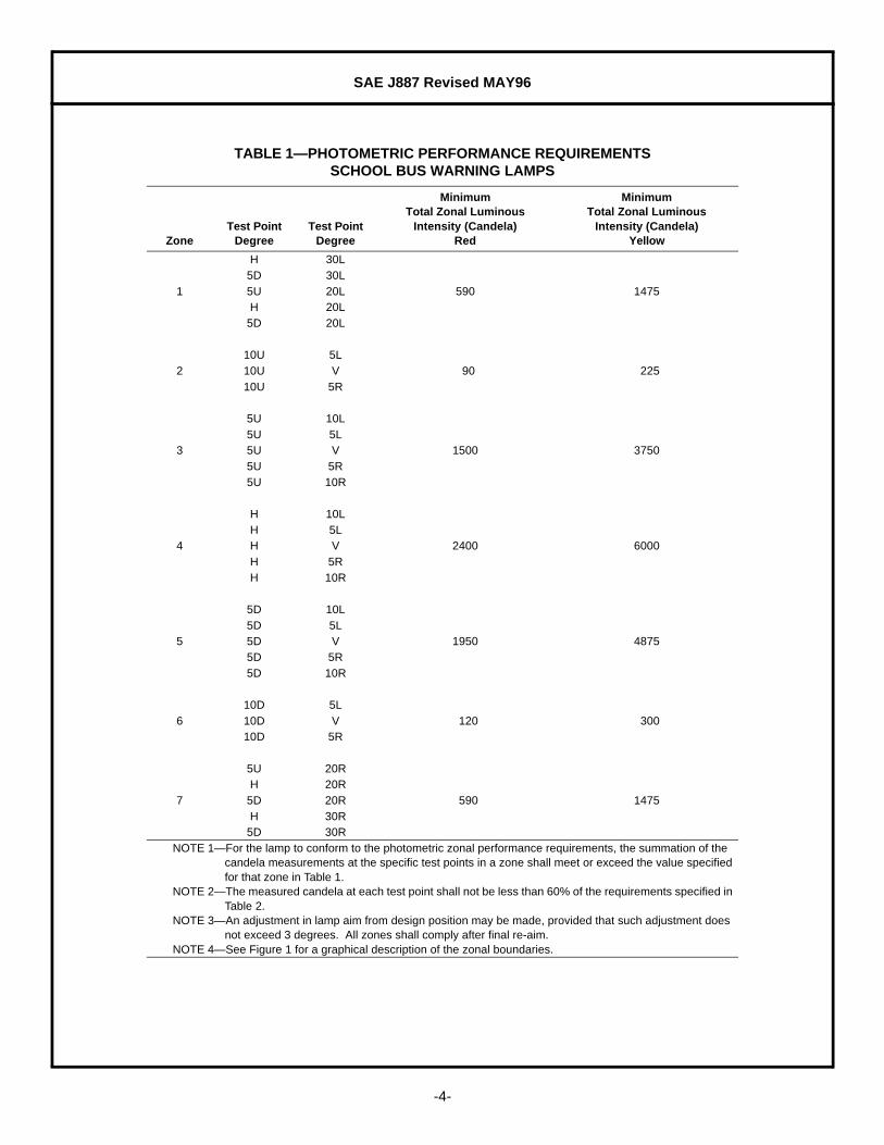
TABLE 1—PHOTOMETRIC PERFORMANCE REQUIREMENTSSCHOOL BUS WARNING LAMPS
ZoneTest Point
DegreeTest Point
Degree
MinimumTotal Zonal Luminous
Intensity (Candela)Red
MinimumTotal Zonal Luminous
Intensity (Candela)Yellow
H 30L5D 30L
1 5U 20L 590 1475H 20L
5D 20L
10U 5L2 10U V 90 225
10U 5R
5U 10L5U 5L
3 5U V 1500 37505U 5R5U 10R
H 10LH 5L
4 H V 2400 6000H 5RH 10R
5D 10L5D 5L
5 5D V 1950 48755D 5R5D 10R
10D 5L6 10D V 120 300
10D 5R
5U 20RH 20R
7 5D 20R 590 1475H 30R
5D 30RNOTE 1—For the lamp to conform to the photometric zonal performance requirements, the summation of the
candela measurements at the specific test points in a zone shall meet or exceed the value specified for that zone in Table 1.
NOTE 2—The measured candela at each test point shall not be less than 60% of the requirements specified in Table 2.
NOTE 3—An adjustment in lamp aim from design position may be made, provided that such adjustment does not exceed 3 degrees. All zones shall comply after final re-aim.
NOTE 4—See Figure 1 for a graphical description of the zonal boundaries.

SAE J887 Revised MAY96
-5-
FIGURE 1—GRAPHICAL DESCRIPTION OF THE ZONAL BOUNDARIES

SAE J887 Revised MAY96
-6-
TABLE 2—PHOTOMETRIC DESIGN GUIDELINESSCHOOL BUS WARNING LAMPS
Test PointDegree
Test PointDegree
MinimumLuminous Intensity
(Candela)Red
MinimumLuminous Intensity
(Candela)Yellow
5L 20 50
10U V 50 125
5R 20 50
20L 150 375
10L 300 750
5L 300 750
5U V 300 750
5R 300 750
10R 300 750
20R 150 375
30L 30 75
20L 180 450
10L 400 1000
5L 500 1250
H V 600 1500
5R 500 1250
10R 400 1000
20R 180 450
30R 30 75
30L 30 75
20L 200 500
10L 300 750
5L 450 1125
5D V 450 1125
5R 450 1125
10R 300 750
20R 200 500
30R 30 75
5L 40 100
10D V 40 100
5R 40 100
NOTE 1—An adjustment in lamp aim from design position may be made provided that such adjustment does not exceed 3 degrees. The lamp should meet or exceed the values specified in Table 2 after final re-aim.
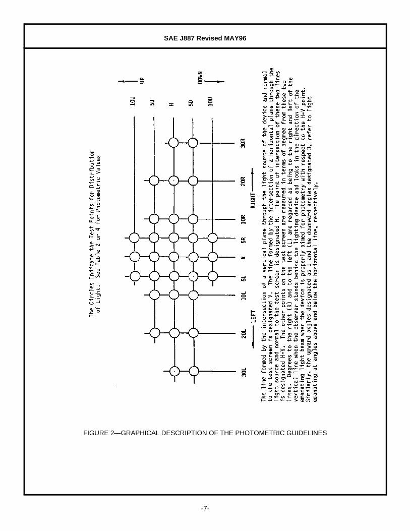
NOTE 2—See Figure 2 for a graphical description of photometric design guidelines.
SAE J887 Revised MAY96
-7-
FIGURE 2—GRAPHICAL DESCRIPTION OF THE PHOTOMETRIC GUIDELINES

SAE J887 Revised MAY96
-8-
TABLE 3—PHOTOMETRIC PERFORMANCE REQUIREMENTS (ALTERNATE METHOD)SCHOOL BUS WARNING LAMPS
ZoneTest Point
DegreeTest Point
Degree
MinimumTotal Zonal Flash Energy
(Candela Seconds)Red
MinimumTotal Zonal Flash Energy
(Candela Seconds)Yellow
H 30L
5D 30L
1 5U 20L 141 351
H 20L
5D 20L
10U 5L
2 10U V 22 54
10U 5R
5U 10L
5U 5L
3 5U V 360 890
5U 5R
5U 10R
H 10L
H 5L
4 H V 571 1426
H 5R
H 10R
5D 10L
5D 5L
5 5D V 465 1157
5D 5R
5D 10R
10D 5L
6 10D V 30 72
10D 5R
5U 20R
H 20R
7 5D 20R 141 351
H 30R
5D 30R
NOTE 1—For the lamp to conform to the photometric zonal performance requirements, the summation of the flash energy measurements at the specific test points in a zone shall meet or exceed the value specified for that zone in Table 3.
NOTE 2—The measured flash energy at each test point shall not be less than 60% of the requirements specified in Table 4.
NOTE 3—An adjustment in lamp aim from design position may be made, provided that such adjustment does not exceed 3 degrees. All zones shall comply after final re-aim.
NOTE 4—See Figure 1 for a graphical description of the zonal boundaries.
SAE J887 Revised MAY96
-9-
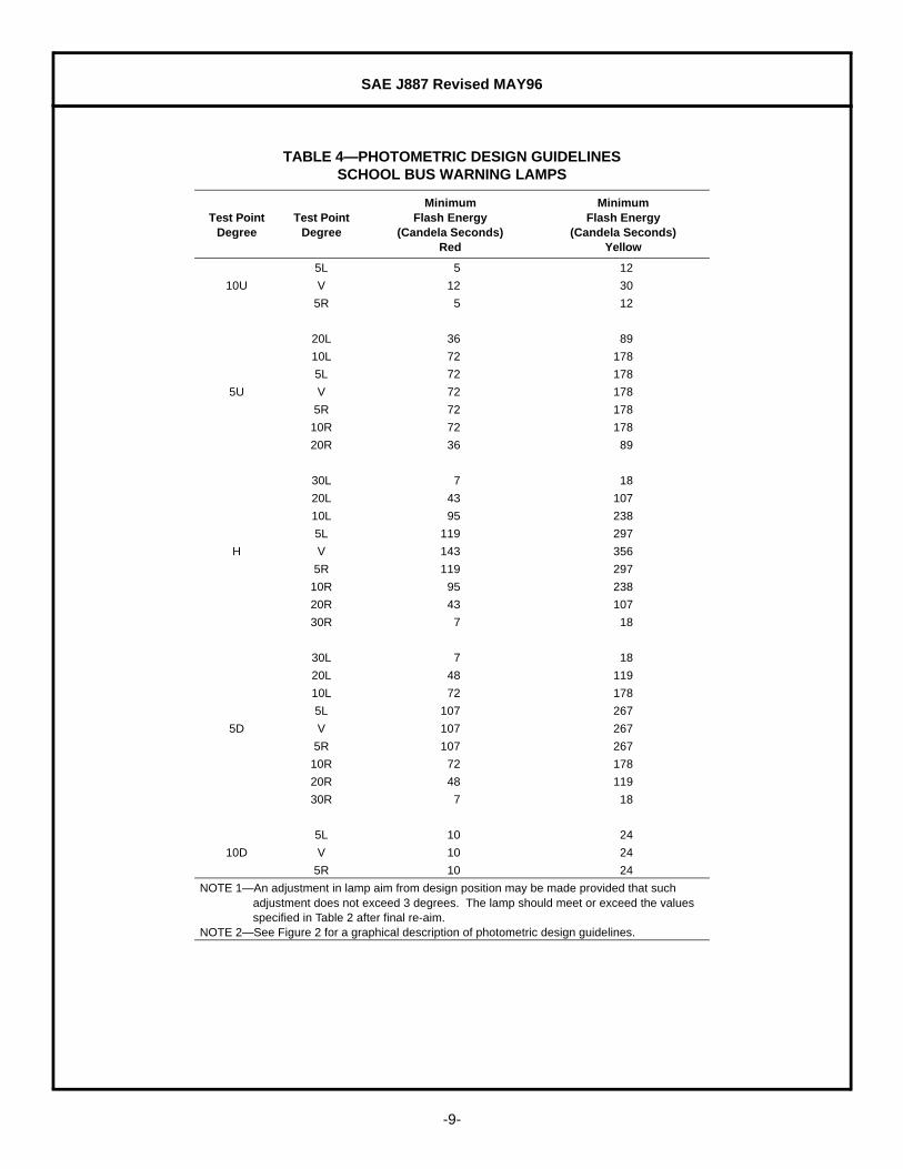
TABLE 4—PHOTOMETRIC DESIGN GUIDELINESSCHOOL BUS WARNING LAMPS
Test PointDegree
Test PointDegree
MinimumFlash Energy
(Candela Seconds)Red
MinimumFlash Energy
(Candela Seconds)Yellow
5L 5 12
10U V 12 30
5R 5 12
20L 36 89
10L 72 178
5L 72 178
5U V 72 178
5R 72 178
10R 72 178
20R 36 89
30L 7 18
20L 43 107
10L 95 238
5L 119 297
H V 143 356
5R 119 297
10R 95 238
20R 43 107
30R 7 18
30L 7 18
20L 48 119
10L 72 178
5L 107 267
5D V 107 267
5R 107 267
10R 72 178
20R 48 119
30R 7 18
5L 10 24
10D V 10 24
5R 10 24
NOTE 1—An adjustment in lamp aim from design position may be made provided that such adjustment does not exceed 3 degrees. The lamp should meet or exceed the values specified in Table 2 after final re-aim.
NOTE 2—See Figure 2 for a graphical description of photometric design guidelines.
SAE J887 Revised MAY96
-10-
7.6 The warning lamps should be mounted on the same horizontal centerline as high as practical at the front abovethe windshield and on the same horizontal centerline as high as practical at the rear so that the lower edge ofthe lenses is not lower than the top line of the side window openings.
7.7 The visibility of the front warning lamps to the front, and of the rear warning lamps to the rear, should beunobstructed by any part of the vehicle from 10 degrees above to 10 degrees below horizontal and from30 degrees to the right to 30 degrees to the left of the centerline of the lamps.
7.8 To improve the effectiveness of the signal, the area of the vehicle immediately surrounding the warning lampextending outward approximately 70 mm should be painted black.
7.9 The lamps should be mounted on the school bus with their aiming plane vertical and normal to the vehiclelongitudinal axis. If lamps are aimed or inspected with a mechanical headlamp aimer, the graduation settingsfor aim should be 0 down and 0 sideways. The limits for inspection should be from 5 up to 5 down and from10 right to 10 left.
8. Test Equipment Guidelines—The following guidelines apply to photometric test equipment and are not partof the technical requirements for the lamps:
8.1 A pulse integrating photometer or other accepted means of measuring pulsed light signals should have thefollowing:
a. Response Time—1 µs or less.b. Sensor Response—Sensor should be corrected to that of the 1931 C.I.E. standard observer
(2 degrees) photopic response curve. Sensor should be calibrated for the color of the light beingmeasured.
c. Range Linearity—Linearity of the sensor and photometer system should be verified over the range ofthe luminous intensities being tested. Linearity deviation should not exceed 2.5% from the calibrationlevel to the extreme luminous intensity values measured.
8.2 The regulated DC power supply should have the following minimum requirement:
a. Line regulations: ±0.1%b. Load regulation: ±0.1%c. Ripple voltage: ±1.4%d. Stability: ±0.1% during test
9. Notes
9.1 Marginal Indicia—The change bar (l) located in the left margin is for the convenience of the user in locatingareas where technical revisions have been made to the previous issue of the report. An (R) symbol to the leftof the document title indicates a complete revision of the report.
PREPARED BY THE SAE EMERGENCY WARNING DEVICES STANDARDS COMMITTEEOF THE SAE LIGHTING COORDINATING COMMITTEE
SAE J887 Revised MAY96
Rationale—The changes to SAE J887 include:
a. Reformatting the document to comply with the SAE Technical Standards Board format. This involvesadding References as Section 2 and renumbering subsequent sections.
b. Minimum was added to third column of Tables 1 to 4.c. 7.4—This should be 7.3.d. 5.3, 6.1, 6.3.2, 6.3.3—J1132 has been incorporated into J1383.e. Reference Section—Delete J571 and J1132. Add J1383.f. 5.3—Replace “Sealed Units as described in SAE ... x 200 mm Sealed Beam Headlamp Units” with
“SealedUnits as described in SAE J760a and SAE J1383”g. 6.1—Replace “SAE J571, SAE J760, and SAE J1132” with “SAE J760a and SAE J1383”.h. Typo: “6.1.11, ...” should read “6.1.1, ...”i. 6.3.2—Replace “SAE J571, or SAE J1132” with “SAE J1383”.j. 6.3.3—Replace “SAE J571, SAE J760, or SAE J1132” with “SAE J760a or SAE J1383”.k. 7.3—Replace “devices, ... Alternating Flashers. The ‘on’ “ with “devices, the ‘on’ ”.
Relationship of SAE Standard to ISO Standard—Not applicable.
Application—This SAE Standard provides test procedures, requirements, and guidelines for red and yellowschool bus warning lamps.
Reference Section
SAE J575—Test Methods and Equipment for Lighting Devices and Components for Use on VehiclesLess Than 2032 mm in Overall Width
SAE J576—Plastic Materials for Use in Optical Parts Such as Lenses and Reflectors of Motor VehicleLighting Devices
SAE J578—Color Specification
SAE J602—Headlamp Aiming Device for Mechanically Aimable Headlamp Units
SAE J759—Lighting Identification Code
SAE J760a—Dimensional Specifications for General Service Sealed Lighting Units
SAE J1054—Warning Lamp Alternating Flashers
SAE J1383—Performance Requirements for Motor Vehicle Headlamps
Developed by the SAE Emergency Warning Devices Standards Committee
Sponsored by the SAE Lighting Coordinating Committee
Recommended


![Inhaltsverzeichnis · [ I ] SAE-Flansche (ISO 6162) / SAE-flanges (ISO 6162) Seite / Page SAE-Flanschhälften / SAE-split flange halves FH-... 1 SAE-Vollflansch / SAE-flange](https://img.pdfslide.net/doc/110x75/5b1675127f8b9a546d8c0fe1/inhaltsverzeichnis-i-sae-flansche-iso-6162-sae-flanges-iso-6162-seite.jpg)


![TOYOTA-TERMINOLOGIE [ ]- SAE-ABKÜRZUNGEN SAE …](https://img.pdfslide.net/doc/110x75/62bbb323bf7def5b7910eaf4/toyota-terminologie-sae-abkrzungen-sae-.jpg)