A-1
SAFETY PRECAUTIONS(Read these precautions before using.)
When using Mitsubishi equipment thoroughly read this manual and the associated manualsreferenced within.
Also pay careful attention to safety and handle the module properly. These precautions apply onlyto Mitsubishi equipment. Refer to the CPU module user's manual for a description of the PLCsystem safety precautions.
These SAFETY PRECAUTIONS classify the safety precautions into two categories: "DANGER"and "CAUTION".
Procedures which may lead to a dangerous condition and cause deathor serious injury if not carried out properly.
Procedures which may lead to a dangerous condition and causesuperficial to medium injury, or physical damage only, if not carried outproperly.
Depending on circumstances, procedures indicated by CAUTION may also be linked toserious results.In any case, it is important to follow the directions for usage.
Store this manual in a safe place so that you can take it out and read it whenever necessary.Always make it available to the end user.
USE PRECAUTIONS
DANGERThis manual is an introduction the GPPWmodule and is intended to facilitate its use.Be familiar with GPPW functions beforeconnecting the system control units (CPU, I/Ounit, special unit to external equipment) forlearning.Operation mistakes could cause errors ordamage to the module.
CAUTION
DANGER
A-2
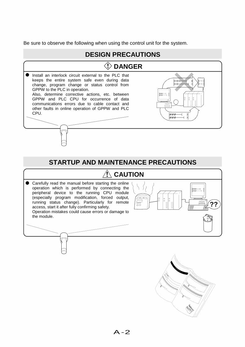
Be sure to observe the following when using the control unit for the system.
DESIGN PRECAUTIONS
DANGERInstall an interlock circuit external to the PLC thatkeeps the entire system safe even during datachange, program change or status control fromGPPW to the PLC in operation.Also, determine corrective actions, etc. betweenGPPW and PLC CPU for occurrence of datacommunications errors due to cable contact andother faults in online operation of GPPW and PLCCPU.
STARTUP AND MAINTENANCE PRECAUTIONS
CAUTION
??
Manual
Carefully read the manual before starting the onlineoperation which is performed by connecting theperipheral device to the running CPU module(especially program modification, forced output,running status change). Particularly for remoteaccess, start it after fully confirming safety.Operation mistakes could cause errors or damage tothe module.

A-3
Revisions*The manual number is noted at the lower left of the back cover.
Print Date *Manual Number RevisionSep. 1999 IB(NA)-0800057-A First edition
1999 MITSUBISHI ELECTRIC CORPORATION
This manual confers no industrial property rights or any rights of any other kind, nor does it confer any patent licenses.
Mitsubishi Electric Corporation cannot be held responsible for any problems involving industrial property rights which
may occur as a result of using the contents noted in this manual.

A-4
Thank you very much for purchasing Mitsubishi General Purpose
PLC MELSEC Series.
This manual "Starting GPPW" is intended for first-time users of the
Windows version GPP Software Package GPPW.
This manual uses screen display examples and figures to help you
understand procedures for installation on the personal computer,
start-up operations, basic principles of GPPW, circuit creation and
editing.
With this manual, anyone can easily master the operation of the
GPPW.
To help you master operations with the GPPW, this manual
demonstrates the most frequently used GPPW functions.
λ Microsoft Windows, Microsoft Windows NT, Microsoft Word and
Microsoft Excel are trade marks of Microsoft Corporation in the
U.S.A. and other countries.
Company names and product names in the text are trademarks
or registered trademarks of companies.
Introduction

A-5
This manual consists of the following five parts.
Part 1 Getting started
Explains GPPW features, installation procedures,
GPPW system configuration and operation flow.
Part 2 Basics
Explains mouse basic operations, GPPW screen
configuration and GPPW basic principles.
Part 3 Offline operations
Explains operations required for circuit creation,
the method and editing of circuit creation and
comment writing, and printing.
Part 4 Online operations
Explains basic operations for online operation.
Part 5 Useful functions
Explains useful functions for GPPW operations.
Parts of this Manual

A-6
Sections in this manual are assigned to even page numbers. The section titles show
actual operations.
Operations in this manual are described as ACPU for PLC series.
Function keys are described as GPPQ type. (Refer to Part 5, 1.2.)
How to use this manual
T h is section descr ibes ope ra tions fo r se tting P L C ser ies and P L C type and c rea ting a ne w p ro jec t.
Only one project can be opened with GPPW.
To open and edit multiple projects, it is necessary to start multiple GPPWs.
Short cut
keyNCtrl
3 -1
38
Offline operations
A PLC CPU is only a box if a program is not installed.
It is necessary to create a circuit (program) that controls the PLC.
This chapter describes creating the project required for the circuit and its reading.
1 Creating a circuit
1.1 Creating a new project
1) Click on the tool bar.
2) Click the [PLC series] from the listbuttons.Select the appropriate typecorresponding to your PLC series.
1) Click
2) Click for selection.
To the following pageTo the following page
Choose "ACPU" here
Part number and titleDescribes the part numberand the title.
Chapter number and titleDescribes the chapter numberand the title.
Describes the chapter details.
Chapter details
Section number and title
Describes the section numberand the title.
Section details
Describes the section details.
Describes the short cut key onthe keyboard that allows directaccess.
Short cut key
To the following page
Description continues to thefollowing page.

A-7
• Operation outline number corresponds to the operation description number.
• The left half of the page shows screens for operation procedures. The right half of the
page shows operation procedures for the screens.
• Keys in this manual show general key descriptions available for any type of keyboard.
3-2
Creating a circuit - Chapter 1 -
From previous pageFrom previous page
(Setting a project name. )
3) Click the list button to select the[PLC type].Select the appropriate type corres-ponding to your PLC CPU series.
4) Check this to set the project name.
5) Set the drive/path, project nameand heading.
6) Click the OK button.
7) A new project opens.
For project ····
Part 2, 2.1 .
7) A new project opens
6)Click here
4) Check
3) Click for selection
5) Set these items
Click the Browse button and thefollowing dialog box appears forsetting.
Part 2, 2.4.
From previous page
Description continues from theprevious page.
Chapter number and title
Describes the chapter numberand title.
Operation description
Describes the operationprocedures for the number.
Operation outlineDescribes operation outline.(corresponding to the operationdescription number)
Point
Important information for ope-ration is shown.
Supplementary operation andreference information isprovided.
Hint
Reference
Shows reference.
Operation screen
Shows screen status for ope-ration.
Page No.
Shows page No.(Part No. - Page No.)

A-8
[Contents]Safety PrecautionsRevisionsIntroductionParts of This ManualHow to Use This ManualAbbreviations
1Getting started
1 Getting started
1.1 What GPPW can do....................................................................1- 1
1.2 Installing operation of GPPW ....................................................1- 7
1.3 Using the license key FD to ready GPPW to start......................1-13
1.4 Uninstalling operation of GPPW .................................................1-15
1.5 Required items to gain access to PLC .......................................1-19
1.6 Operation flow.............................................................................1-21
2Basics
1 Introduction
1.1 How to use the mouse................................................................2- 1
1.2 Common mouse operations .......................................................2- 3
1.3 Screen configuration...................................................................2- 7
2 Basics for GPPW operations
2.1 What is a "project"? ....................................................................2- 9
2.2 Starting GPPW ...........................................................................2-11
2.3 Ending a GPPW session ............................................................2-13
2.4 Designation of project.................................................................2-15
2.5 Frequent operations....................................................................2-19

A-9
3Offline
operations
1 Creating a circuit
1.1 Creating a new project................................................................3- 1
1.2 Creating a circuit with list expressions (mnemonic language) ...3- 3
1.3 Creating a circuit with tool buttons..............................................3- 7
1.4 Converting a created circuit........................................................3-11
1.5 Creating a program with list commands .....................................3-13
1.6 Saving a created project.............................................................3-15
1.7 Reading a saved project.............................................................3-17
2 Editing a circuit
2.1 Correcting part of a circuit ..........................................................3-19
2.2 Cutting and copying a circuit block .............................................3-21
2.3 Inserting or deleting a line ..........................................................3-25
2.4 Creating and deleting a ruled line...............................................3-27
3 Searching a circuit
3.1 Searching with a designated device ...........................................3-29
3.2 Searching with a step No............................................................3-31
4 Replacing within a circuit
4.1 Replacing with a designated device ...........................................3-33
4.2 Replacing open contact with close contact and vice versa ........3-37
5 Explaining circuit components
5.1 Creating device comments .........................................................3-43
5.2 Creating statements for each circuit block .................................3-47
5.3 Creating a note for coil and application instruction.....................3-49
6 Editing comments
6.1 Correcting device comments ......................................................3-51
6.2 Deleting (cutting) device comments ...........................................3-53
6.3 Copying device comments .........................................................3-57
6.4 Searching statements and notes ................................................3-59
6.5 Correcting statements and notes................................................3-61

A-10
3Offline
operations
7 Printing
7.1 Printing a circuit ..........................................................................3-63
7.2 Printing contacts or coils in use ..................................................3-65
7.3 Printing the device in use ...........................................................3-67
7.4 Printing a list of device comments in use ...................................3-69
4Online
operations
1 Writing and reading to/from the PLC CPU
1.1 Specifying the PLC CPU you want to access.............................4- 1
1.2 Writing data to the PLC CPU......................................................4- 7
2 Monitoring PLC status
2.1 Monitoring circuit status..............................................................4- 9
2.2 Monitoring designated devices ...................................................4-13
3 Debugging a created circuit
3.1 Turning ON/OFF contact positively ............................................4-15
3.2 Executing a program step by step ..............................................4-17
4 Online change
4.1 Writing data during a run of the PLC CPU .................................4-19
4.2 Changing data during monitoring, and writing during a run .......4-21
5Useful
functions
1 Offline operations
1.1 Associating multiple programs....................................................5- 1
1.2 Changing function keys in GPPA, GPPQ, and MEDOC formats .5- 5
1.3 Setting the designated projects for quick start-up ......................5- 7
1.4 Converting files from GPPA format to GPPW format .................5- 9
1.5 Changing project PLC type.........................................................5-17
2 Operations with Windows functions
2.1 Using Excel files as device comment .........................................5-19
2.2 Using Word files as device comment .........................................5-21
2.3 Opening and editing multiple projects ........................................5-23

A-11
5Useful
functions
3 Using Logic Test functions
3.1 Learning operation procedures...................................................5-27
3.2 Creating emulation of I/O and special unit ................................5-29
3.3 Monitoring device status.............................................................5-33
3.4 Using the timing chart for monitoring..........................................5-37
AppendixAppendix
App.1 Short cut key list ..................................................................App- 1
App.2 Circuit creation list ...............................................................App- 7
Index

A-12
Abbreviation
• GPPAAbbreviation of Type SW IVD-GPPA GPP software package.
• GPPQAbbreviation of Type SW IVD-GPPQ GPP software package.
• MEDOCAbbreviation of Type SW IM-MEDOC software package. * MEDOC is a programming software package used out of Japan.
• GPPWAbbreviation of Type SW4D5C-GPPW software package.
• WindowsAbbreviation of Microsoft Windows 95 , Microsoft Windows 98 andMicrosoft Windows NT Work Station 4.0.
• Logic Test function (LLT)Abbreviation of Type SW4D5C-LLT ladder logic test tool softwarepackage.
Part 1 Getting started
Part 2 Basics
Part 3 Offline operations
Part 4 Online operations
Part 5 Useful functions
Appendix


Part 1 1
Getting Started
1. Getting Started1.1 What GPPW can do .......................................................... 1- 1
1.2 Installing operation of GPPW............................................. 1- 7
1.3 Using the license key FD to ready GPPW to start.............. 1-13
1.4 Uninstalling operation of GPPW ........................................ 1-15
1.5 Required items to gain access to PLC............................... 1-191.6 Operation flow ................................................................... 1-21
1

1-1
1 Getting started
GPPW is a programming software package that operates on Windows.
Since it is used on Windows machines, operation performance is much better than the
conventional GPPA and GPPQ.
This chapter explains information you need for GPPW operation.
1 Getting started
1.1 What GPPW can do
This section explains functions and features of GPPW.
——Easy operation on Windows——
The program is easy to understand and can be operated on Windows.
Circuits can be easily and quicklycreated with the tool bar, the menu bar,the program list window.
Since the program is operated onWindows, you can easily cut, copy andpaste between projects.
Completely operated on Windows
1-2
Getting started - Chapter 1 -
——List expressions (mnemonic language)/lists/SFCs can be input——
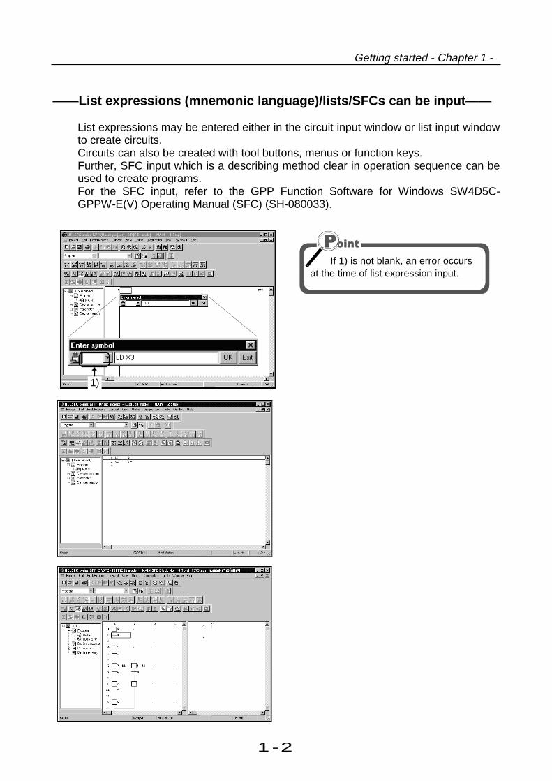
List expressions may be entered either in the circuit input window or list input windowto create circuits.Circuits can also be created with tool buttons, menus or function keys.Further, SFC input which is a describing method clear in operation sequence can beused to create programs.For the SFC input, refer to the GPP Function Software for Windows SW4D5C-GPPW-E(V) Operating Manual (SFC) (SH-080033).
1)
If 1) is not blank, an error occursat the time of list expression input.

1-3
1 Getting started
——Compatible function keys with GPPA, GPPQ and MEDOC——
The GPPW functions keys are compatible with those of GPPA, GPPQ and MEDOC.This facilitates smooth conversion from conventional package to GPPW.
GPPA format
GPPQ format
M E D O C fo rm at
——A circuit can be used between multiple projects.——
With cut, copy and paste functions, a circuit can be used between multiple projects.
Cut, copy and paste
Part 5, 1.2.
Part 5, 2.3.

1-4
Getting started - Chapter 1 -
——A comment developed in a spreadsheet software such as Excel canbe used——
With cut, copy and paste functions, a comment developed in a spreadsheet software
such as Excel can be used.
1) Copy
Part 5, 2.1.
2) Paste

1-5
1 Getting started
——Debugging can be made in offline——
With the Logic Test Function (LLT), debugging can be performed using Monitor or
Test from GPPW, without debugging equipment such as a PLC.
Logic Test function (LLT) is optional.If debugging is required in offline, it hasto be purchased separately.
GPPW's debugging functions that can be performed by the Logic Test function (LLT)• Circuit monitor, device monitor• Device test• PLC writing• PLC diagnostics• Skip execution• Partial operation• Step execution• Remote operation• Program monitor list• I/O system setting function ---------- With simple settings, this function simulates the
operation of an external device.• Device memory monitor function -- • Monitors the device memory states.
• Shows a device ON/OFF chart.
Logic Test function (LLT)
With Logic Test function (LLT),debugging can be made in offline.

1-6
Getting started - Chapter 1 -

1-7
1 Getting started
1.2 Installing operation of GPPW
To use GPPW, it is necessary to install the License key FD after installing GPPW.
Installation of GPPWInstallation of Licensekey FD Start of GPPW
1) After turning on the power of thepersonal computer, make sure thatWindows has started.
2) Insert CD-ROM into CD-ROM drive.
3) Click the Start button.
To the following pageTo the following page
4) Click [Programs] - [Windows Explor-er] menu.
2) Insert CD-ROMinto CD-ROM drive
1) Start Windows
3) Click here
4) Click here

1-8
Getting started - Chapter 1 -
From previous pageFrom previous page
5) Click the CD-ROM drive withGPPW.
6) Double click the "SETUP.EXE".
End all other applications on theWindows before installation.
7) Click OK after confirming that
other applications are not running.
If the message shown on the left
appears, click the Cancel button,
uninstall the product, and thenperform installation.
If the message shown on the left
appears, click the OK button,
uninstall the license key FD, andthen perform installation.
To the following pageTo the following page
If the message shown on the leftappears, always install the productin the personal computer where theproduct of old version has beeninstalled.
Windows Explorer starts
6) Double click here
5) Click here
7) Click here
Click here
Click here
1-9
1 Getting started
From previous pageFrom previous page
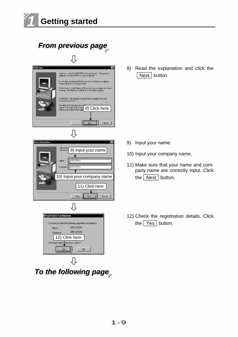
8) Read the explanation and click the
Next button.
9) Input your name.
10) Input your company name.
11) Make sure that your name and com-pany name are correctly input. Click
the Next button.
To the following pageTo the following page
12) Check the registration details. Click
the Yes button.
10) Input your company name
11) Click here
9) Input your name
8) Click here
12) Click here

1-10
Getting started - Chapter 1 -
From previous pageFrom previous page
13) Input the product ID number and
click the Next button.
The product ID number is shown onthe "Software Registration" accom-panying the product.
To the following pageTo the following page
14) Click the check box if you want toimport to GPPW the data output asa printout data file on MELSECMEDOC.
15) Click the Next button.
13) Input the productID number
14) Click here
15) Click here

1-11
1 Getting started
From previous pageFrom previous page
16) Click the Next button and the foll-
owing dialog box appears to set theinstallation destination.
Click the Browse button and thefollowing dialog box appears to setthe installation destination.
17) Installation starts.
18) Installation has completed.
Click the OK button.
If the message shown on the leftappears, Windows must berestarted.
Click the OK button to restart
Windows.This completes the installation ofGPPW.To start GPPW, the license key FDmust be installed.
If installation fails midway, deleteGPPW and install it again.
18) Click here
16) Click here
17) Installing
Click here

1-12
Getting started - Chapter 1 -
——Installing operation of the Logic Test function (LLT)——
The installing operation of the Logic Test function is similar to that of GPPW. Theinstallation of the License key FD is also similar.Since the Logic Test function is started from GPPW, its icon is not registered.To confirm the installation of the Logic Test function, click the [Tools]-[Start ladderlogic test] menu of GPPW and make sure that the Logic Test function starts.If the following screen appears, the function was installed properly.

1-13
1 Getting started
1.3 Using the License key FD to ready GPPW to start
The License key FD is designed to ready GPPW to start.After installing GPPW, install the License key FD to make GPPW ready to start.
1) Insert the License key FD into theFD drive.
2) Click the Start button.
3) Click [Programs] - [Windows Explor-er] menu.
To the following pageTo the following page
4) Click the FD drive which containsthe License key FD.
5) Double click the "SETUP.EXE".
1) Insert License keyFD into FD drive.
2) Click here
3) Click here
Windows Explorer starts
5) Double click here
4) Click here

1-14
Getting started - Chapter 1 -
From previous pageFrom previous page
6) Click the key picture.
7) Confirm the message and click
OK .
8) As the installation of the License
key FD is complete, click Close .
This allows GPPW to be started.
Save the License key FDcarefully and take charge of it sothat you can readily identify thepersonal computer where it hadbeen installed.If you mislay the License key FDor if the License key FD does notmatch the personal computerwhere it had been installed,installation/uninstallation cannotbe performed.
8) Click here
7) Click here
6) Click here

1-15
1 Getting started
1.4 Uninstalling operation of GPPW
To uninstall GPPW, it is necessary to uninstall the License key FD and then uninstallGPPW.
1) Insert the License key FD into theFD drive, and click the [Start] -[Programs] - [Windows Explorer]menu to start Explorer.
2) Click the FD drive which containsthe License key FD.
3) Double click the "SETUP.EXE".
4) Click the key picture.
To the following pageTo the following page
5) Since uninstallation of the License
key FD is complete, click Close .
5) Click here
Windows Explorer starts
2) Click here
4) Click here
3) Double click here

1-16
Getting started - Chapter 1 -
From previous pageFrom previous page
6) Click the [Start]-[Settings]-[ControlPanel] menu to start Control Panel.
7) Double click Add/RemovePrograms.
To the following pageTo the following page
8) Choose the software package to bedeleted.
9) Click Add/Remove... .
6) Click here
7) Double click here
8) Choose software to be deleted.
9) Click here

1-17
1 Getting started
From previous pageFrom previous page
10) Click Yes .
If the message shown on the left
appears, click OK , uninstall
GPPW, and then uninstall theLicense key FD.
If the display provided on the left
appears, click No to All .
Choosing Yes deletes the sharedfile of the Windows-compatibleMELSEC software packagegroup. To delete only GPPW,therefore, click No to All.
To the following pageTo the following page
11) Uninstallation starts.
Click here
10) Click here
Click here
11) Uninstallation in progress

1-18
Getting started - Chapter 1 -
From previous pageFrom previous page
12) As the message appears oncompletion of uninstallation, click
the OK button.
This completes uninstallation.
If the message shown on the leftappears, open Explorer, check files,and remove unnecessary files.It should be noted that if youremove any necessary file bymistake, the other applications maynot start.
——Uninstalling operation of the Logic Test function (LLT)——
The uninstalling operation of the Logic Test function (LLT) is similar to that of GPPW.
12) Click here
The message shown

1-19
1 Getting started
1.5 Required items to gain access to PLC
This section explains the required devices and software to gain access to PLC.
OS
Windows
GPP function
SW4D5C-GPPW
Personal computer CPUPentium 133MHz or betterrecommended.
Memory32 MB or better recommended.
DisplayResolution of 800 × 600 pixelsor better
PLC
A, QnA, Q, FX seriesmotion controller
Communication
LLT function
SW4D5C-LLT
Free space of hard disk 60MBor more (including LLT)
This product is optional andshould be purchasedseparately when required.

1-20
Getting started - Chapter 1 -
——Types of communication routes——
This section describes communication routes for direct link with the PLC CPU.For details of communication routes other than direct link and each equipment, refer theGPP Function Software for Windows SW4D5C-GPPW-E(V) Operating Manual (SH-080032).
(1) Direct link to ACPU or QnACPUCommunication is performed with the direct link between the COM port of the personalcomputer and the RS-422 connector of the ACPU or QnACPU.
PLCPersonalcomputer
RS-422/232Cconversion cable
RS-422/232Cconverter
RS-232Ccable
RS-422cable
(2) Direct link to QCPU (Q mode)Communication is performed with the link between the COM port of the personalcomputer and the RS-232 connector or USB connector of the QCPU (Q mode).
USB cable
RS-232 cable
PersonalComputer
PLC
(3) Direct link to QCPU (A mode)Communication is performed with the link between the COM port of the personalcomputer and the RS-232 connector of the QCPU (A mode).
PersonalComputer
RS-232 cablePLC

1-21
1 Getting started
1.6 Operation flow
This section explains operations from start-up to end of GPPW.
Part 3, 1.2 and 1.3.
A circuit is created.
Part 3,Chapter 5.
An explanation is created.
Part 3, Chapter 2.
A circuit is edited.
Part 3, Chapter 6.
A comment is edited.
Part 3, 1.4.
Created program isconverted.
Part 2, 2.2.
Start GPPW.
Part 3, 1.1.
A new project is created.
Part 3, 1.7.
A saved project is read.
A saved project is read.(When a new project is created)
(When an explanation is added to a circuit)
1)
(When a circuit and explanation is created again)
(When a comment is edited)(When a circuit is edited)
(When a circuit is created)

1-22
Getting started - Chapter 1 -
1)
Debugging operationsare made.
(When PLC CPU statusis monitored)
(When debugging)
A project is saved.
Part 3, 1.6.
Write data on PLCCPU.
PLC CPU status ismonitored.
Stop PLC CPU.
Set PLC CPU toRUN status.
Part 2, 2.3.
End GPPW.
Make Connection Setup.
Part 4, 1.1.
To change the PLC mode of theACPU, QnACPU or QCPU, useeither of the following switches ofthe corresponding PLC CPU to setthe mode.
For ACPU, QnACPU<RUN/STOP key switch>
For QCPU<RUN/STOP switch>
RESET
STOP
RESET
L.CLR RUN
STOP RUN

1-23
1 Getting started

Part 2
2
Basics
1. Introduction1.1 How to use the mouse ........................................................ 2- 1
1.2 Common mouse operations ................................................ 2- 3
1.3 Screen configuration ........................................................... 2- 72. Basics for GPPW operations2.1 What is a "project"?............................................................. 2- 9
2.2 Starting GPPW ................................................................... 2-11
2.3 Ending a GPPW session..................................................... 2-13
2.4 Designation of project ......................................................... 2-15
2.5 Frequent operations ........................................................... 2-19
2

2-1
2 Basics
The most frequent operation in GPPW is using a mouse. A mouse is an indispensable
item for using the Windows software package.
This chapter explains basic mouse operations and GPPW screen configurations.
1 Introduction
1.1 How to use the mouse
Click, double click and drag with a mouse is explained.
——Left click (hereinafter referred to as click)——
ClickPress the left button of the mouse
without moving the mouse position.
——Right click——
ClickPress the right button of the mouse
without moving the mouse position.

2-2
Introduction - Chapter 1 -
——Double click——
Click
Click
Press the left button of the mouse twice
quickly without moving the mouse
position. This operation is for the left
button only, not for the right button.
——Drag——
Keep pressing.
Move the mouse with the left button
pressed. This operation is for the left
button only, not for the right button.

2-3
2 Basics
1.2 Common mouse operations
This section explains common mouse operations such as tab changes, menu selectionsand dialog box operations.
——Scaling of a window——
Drag the edge of the window with amouse to scale the window.
——Scroll bar operation——
Keep clicking mark to scroll thescreen and display the hidden part.Dragging 1) can also scroll the screen.
Scaling can be withdragging
Scroll
1)

2-4
Introduction - Chapter 1 -
——Menu operations——
1) Click the desired menu.
2) Move the cursor to the menu forselection.
3) Additional menus are displayedat .
4) Click the menu for execution.
——Operation of project data list——
Click + marking on the project data list.
The details for the item are displayed.
Double click one of the details and the
corresponding screen appears.
If the project data list is not displayed,
click [View] - [Project data list] menu.
1) Click here
2) Move the cursor to themenu for selection
3) 4) Click here
Click - marking
Click + marking
Double click here
2-5
2 Basics
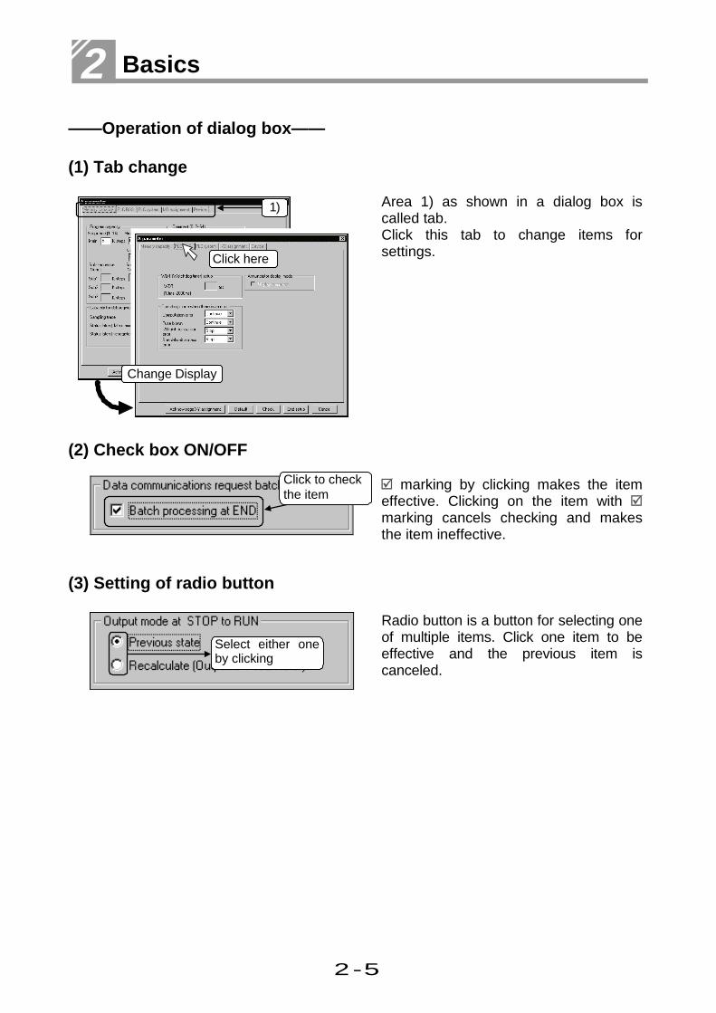
——Operation of dialog box——
(1) Tab change
Area 1) as shown in a dialog box iscalled tab.Click this tab to change items forsettings.
(2) Check box ON/OFF
marking by clicking makes the itemeffective. Clicking on the item with marking cancels checking and makesthe item ineffective.
(3) Setting of radio button
Radio button is a button for selecting oneof multiple items. Click one item to beeffective and the previous item iscanceled.
Change Display
Click here
Select either oneby clicking
1)
Click to checkthe item

2-6
Introduction - Chapter 1 -
(4) Setting of list box
This is to select one out of multipleitems.1) Click to display multiple items.
2) Move the cursor to the item to be set.
3) When the item to be set isdetermined, click and define theitem.
1) Click here
3) Click and define
2) Move the cursor

2-7
2 Basics
1.3 Screen configuration
This section explains how GPPW screens are configured.
1) Title bar
5) Edit screen
3)Tool bar
4) Project data list
6) Status bar
2) Menu bar

2-8
Introduction - Chapter 1 -
1) Title barDisplays the project name which is open.
Ends GPPW byclicking.
Displays the project nameand the path.
Changes the size and ends GPPW. Scales GPPW .
Minimizes GPPW.
2) Menu barThis is most frequently used in GPPW operations.Select the menu and display the drop down menu. Various functions can be used fromthe drop down menu.
3) Tool barFrequent used functions are shown in buttons. This facilitates speedy operations.
Move the mouse cursor to the toolbutton to display brief function of thebutton.
4) Project data listThe Circuit creation screen, dialog box, etc. can be directly read.Data in the project is listed in each category.
5) Edit screenThe Circuit creation screen and comment creation screen are displayed for settings ofcircuit, comment and parameter. Various screens are displayed depending on the editdetails.
6) Status barStatus information of GPPW is displayed.
Displays CapsLock status.
Displays ScrollLock status.
Displays NumLock status.
Displays current mode.
Displaysconnecting
Displays CPU type.
Displays mousecursor position.

2-9
2 Basics
To perform any operation with GPPW, you must understand its basic principles.
This chapter explains the basics required for GPPW operations.
2 Basics for GPPW operations
2.1 What is a "project"?This section explains a GPPW "project."
Project
Program
Program
··················
Device comment
Device comment
Parameter
Device memory
Device default
A project is a collection of componentsincluding a program, device comments,parameter, device memory and devicedefault (for QnACPU, QCPU (Q mode)only).
Item DetailsProgram Sequence program required for operation of PLC CPU.
Device comment
Comment for device of sequence program.Two types of comments are available; “ Common comment” whichis common to projects, and “ Comment for each program” whichvaries on each program.
Parameter Settings for the network or the device range.
Device memory Displays the current device value. Input of a new value changesthe device value.
Device default Value used as a default at the start-up of PLC CPU.(for QnACPU, QCPU (Q mode) only)

2-10
Basics for GPPW operations - Chapter 2 -
——1 project for 1 GPPW——
GPPW can edit only 1 project. To edit multiple projects, it is necessary to startmultiple GPPWs.
——Comparison with GPPA and GPPQ——
GPPW has no system names as were previously used in GPPA and GPPQ. Themachine name has become the project name. A project can be created at anylocation.
GPPA,GPPQ : ..\ GPP (GPPQ) \ USR \ SYSTEM NAME \ MACHNE NAME( \ FILE NAME)
GPPW : .. \ PROJECT NAMEThe drive/path name + project name can be up to 150 characters long.
——Device comment——
There are two comments in GPPW; a common comment and a comment for eachprogram.
Comment type Number of comments DetailsCommoncomment
1 Device comment which is common tothe programs in the project.
Comment foreach program
Same as the number ofprograms
Device comment set for each program.The same name as the program namemust be set.
If the data of two device comments overlap, the priority can be set by clickingthe [Tools]-[Options] menu.The default setting is as follows.
Comment for each program < Common comment
Part 5, 2.3.
GPPQ only

2-11
2 Basics
2.2 Starting GPPW
This section explains starting GPPW.
1) Click the Start button.
To the following pageTo the following page
2) Select the [Programs] menu.
Move the mouse cursor for selection.(Click or double click is not required.)
2) Select
1) Click here

2-12
Basics for GPPW operations - Chapter 2 -
From previous pageFrom previous page
3) Select the [MELSEC Application]menu.
Move the mouse cursor for selection.(Click or double click is not required.)
4) Click the [GPP for Windows].
5) GPPW starts.
Refer to "Start-up" for creation and start-upof the short cut key icon.
5) GPPW starts
4) Click here
3) Select

2-13
2 Basics
2.3 Ending a GPPW session
This section explains the three ways to end a GPPW session.
——Method 1——
1) Click the [Project] menu.
2) Move the cursor and click the [EndGPPW] menu to end GPPW.
——Method 2——
Click at the upper right of thescreen. GPPW ends.
Click here to end the session
Move the cursor
1) Click here
2) Click here to end the session

2-14
Basics for GPPW operations - Chapter 2 -
——Method 3——
1) Click at the upper left of thescreen
2) Move the cursor and click the [Close]menu. GPPW ends.
Short cut
keyAlt F4
——Dialog box appears for the following cases——
(Normal end)
Yes ..........The project ends.
No ............GPPW does not end.
(When circuit is not converted)
Yes ..........GPPW ends without
conversion.
No ............GPPW does not end.
(Circuit editing continues.)
(When the project is not saved)
Yes ..........The project is saved before
ending GPPW.
No ............GPPW ends without saving
the project.
Cancel .....GPPW does not end.
2) Click here to end the session
Move the cursor
1) Click here

2-15
2 Basics
2.4 Designation of project
This section explains reading, saving, deleting and creating a project.
1) Drive of projectDesignates the drive for saving the project.
2) buttonClick this button to move up one directory level.
3) buttonClick this button to display the list of directory names and project names in the currentdirectory.
Double click here to moveup one directory level.
Project name
Directory name
1) 2) 3) 4)
5)
7) 6)

2-16
Basics for GPPW operations - Chapter 2 -
4) buttonClick this button to display the details of directory names and project names in thecurrent directory.
5) Drive/PathDesignates the path which saves the project (where the project is saved).The drive/path can be specified by entering it directly or double clicking the on screendirectory.
6) Project nameDesignates the project name.To designate the project name, input the project name directly or double click theproject name on the screen. Double click the project name for the definition.
7) HeadingDesignates heading for the project.
Project headingDateCPU type
Directory name,project name

2-17
2 Basics
——Let's practice with a project for setting.——
Setting example
Setting action :Saving projectProject name to be saved :FactoryFactory :Program for M plantDrive for saving project :F:\GPPW\GPPW installation drive :D:\MELSEC\GPPW
1) Change from [-d-] to [-f-].
To the following pageTo the following page
2) Double click the drive to change theDrive/Path to "F:\GPPW\".
A project can be created in any directory.
1) Change the projectdrive from [-d-] to [-f-]
2) Double click here
2-18
Basics for GPPW operations - Chapter 2 -
From previous pageFrom previous page
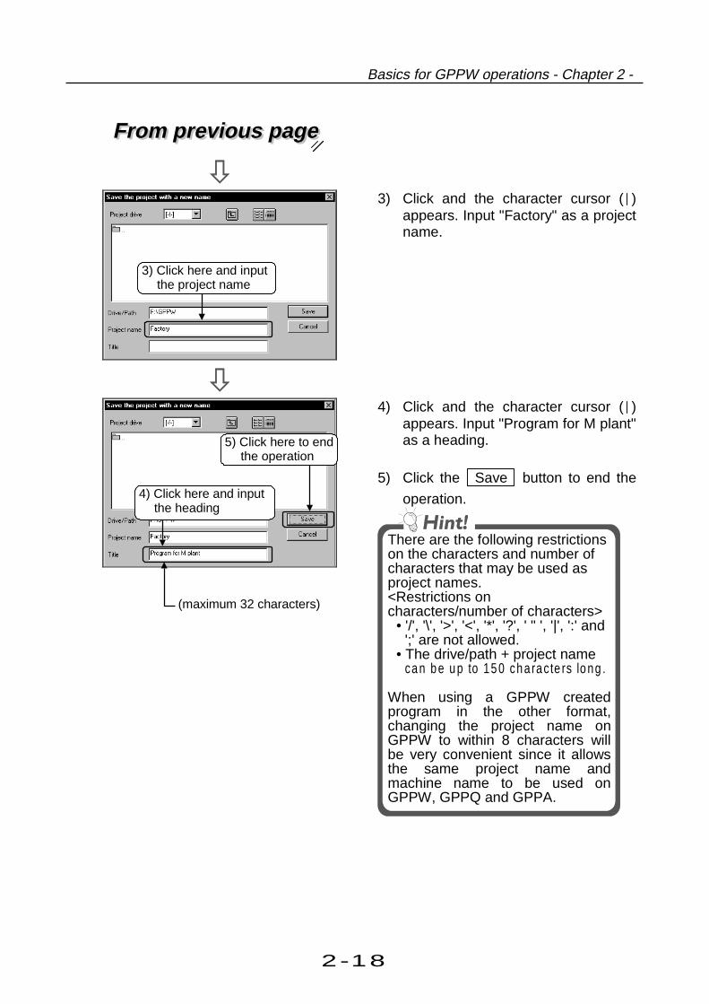
3) Click and the character cursor ( )appears. Input "Factory" as a projectname.
4) Click and the character cursor ( )appears. Input "Program for M plant"as a heading.
5) Click the Save button to end the
operation.
There are the following restrictionson the characters and number ofcharacters that may be used asproject names.<Restrictions oncharacters/number of characters>
• '/', '\', '>', '<', '*', '?', ' " ', '|', ':' and';' are not allowed.
• The drive/path + project nameca n b e u p to 15 0 ch arac te rs lo ng .
When using a GPPW createdprogram in the other format,changing the project name onGPPW to within 8 characters willbe very convenient since it allowsthe same project name andmachine name to be used onGPPW, GPPQ and GPPA.
3) Click here and inputthe project name
4) Click here and inputthe heading
5) Click here to endthe operation
(maximum 32 characters)

2-19
2 Basics
2.5 Frequent operations
This section explains frequent GPPW operations.
——Scaling of circuit.——
Click on the tool bar to enlarge thecircuit.
Click to shrink the circuit.
——Right click——
Right click on the circuit screen or theproject data list. The menu in the leftappears.
(Enlarge)
Right click
(Shrink)

2-20
Basics for GPPW operations - Chapter 2 -
——Display of editing screens——
[Window] menu can change the displayof editing screens.
• Alignment of screens is effective onlyfor windows which are open.
• "Arrange icons" is effective only forwindows which are shown as icons.
Cascade
Select either one
Arrange icons
Tile(left&right)
Tile(top&bottom)

2-21
2 Basics

Part 3
1. Creating a circuit1.1 Creating a new project ........................................................ 3- 1
1.2 Creating a circuit with list expressions (mnemonic language) . 3- 3
1.3 Creating a circuit with tool buttons ...................................... 3- 7
1.4 Converting a created circuit ................................................ 3-11
1.5 Creating a program with list commands .............................. 3-13
1.6 Saving a created project ..................................................... 3-15
1.7 Reading a saved project ..................................................... 3-172. Editing a circuit2.1 Correcting part of circuit ...................................................... 3-19
2.2 Cutting and copying a circuit block...................................... 3-21
2.3 Inserting or deleting a line................................................... 3-25
2.4 Creating and deleting a ruled line........................................ 3-273. Searching a circuit3.1 Searching with a designated device.................................... 3-29
3.2 Searching with a step No. ................................................... 3-314. Replacing within a circuit4.1 Replacing with a designated device .................................... 3-33
4.2 Replacing open contact with close contact and vice versa.. 3-375. Explaining circuit components5.1 Creating device comments.................................................. 3-43
5.2 Creating statements for each circuit block........................... 3-47
5.3 Creating a note for coil and application instruction .............. 3-496. Editing comments6.1 Correcting device comments............................................... 3-51
6.2 Deleting (cutting) device comments .................................... 3-53
6.3 Copying device comments.................................................. 3-57
6.4 Searching statements and notes......................................... 3-59
6.5 Correcting statements and notes ........................................ 3-617. Printing7.1 Printing a circuit .................................................................. 3-63
7.2 Printing contacts or coils in use........................................... 3-65
7.3 Printing device in use.......................................................... 3-67
7.4 Printing a list of device comments in use ............................ 3-69
3
Offline operations 3

3-1
3 Offline operations
A PLC CPU is only a box if a program is not installed.
It is necessary to create a circuit (program) that controls the PLC.
This chapter describes creating the project required for the circuit and its reading.
1 Creating a circuit
1.1 Creating a new project
This section describes setting PLC series and PLC type and creating a new project.Only one project can be opened with GPPW.To open and edit multiple projects, it is necessary to start multiple GPPWs.
1) Click on the tool bar.
Short cut
keyNCtrl
To the following pageTo the following page
2) Click the [PLC series] from the listbuttons.Select the appropriate type corres-ponding to your PLC CPU series.Choose "ACPU" here. 2) Click for selection
1) Click here

3-2
Creating a circuit - Chapter 1 -
From previous pageFrom previous page
(Setting a project name.)
3) Click the list button to select the[PLC type].Select the appropriate type corres-ponding to your PLC CPU series.Choose "A2US(S1)" here.
4) Check this to set the project name.
5) Set the drive/path, project name andheading.
Click the Browse button and thefollowing dialog box appears forsetting.
Part 2, 2.4.
6) Click the OK button.
7) A new project opens.
For project····
Part 2, 2.1.
7) A new project opens
6) Click here
4) Check
3) Click for selection
5) Set these items

3-3
3 Offline operations
1.2 Creating a circuit with list expressions (mnemonic language)
This section explains creating an example circuit with list expressions.To create a circuit, be sure to change the mode to write mode.
X3SET M20
Y25
M20Y20
Circuit to be created Method to create a circuit in the left isexplained.
To the following pageTo the following page
1) Input "LD X3".When the input is made, the circuitinput window opens.If the input is not correct, press the Esc key.
2) If the input is correct, press the Enter key.
• Click the OK button to define theinput.
• Click the Exit button to delete theinput.
1) Input here2) Press the Enter
key

3-4
Creating a circuit - Chapter 1 -
From previous pageFrom previous page
3) Input circuit (X3
) is displayed.
4) Input "SET M20". After the input,press the Enter key.
To the following pageTo the following page
5) Input circuit ( SET M20 ) is displayed.
6) Input "LD M20". After the input,press the Enter key.
4) After input, press the Enter key
3) Circuit is displayed
5) Circuit is displayed
6) After input, press the Enter key

3-5
3 Offline operations
From previous pageFrom previous page
7) Input circuit (M20
) is displayed.
8) Input "OUT Y20".After the input, press the Enter key.
To the following pageTo the following page
9) Input circuit ( Y20 ) is displayed.
10) Input "ORI Y25".After the input, press the Enter key.
7) Circuit is displayed
8) After input, press the Enter key
9) Circuit is displayed
10) After input, press the Enter key

3-6
Creating a circuit - Chapter 1 -
From previous pageFrom previous page
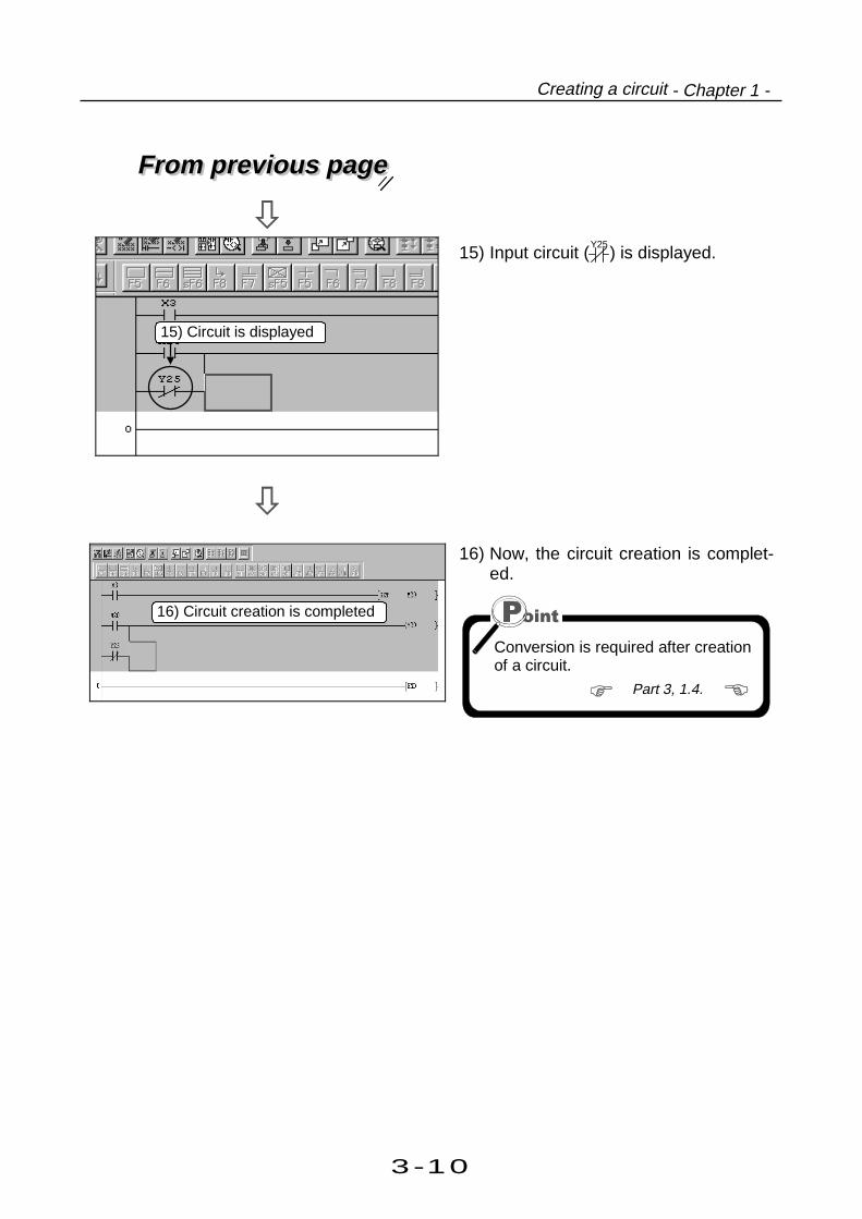
11) Input circuit (Y25
) is displayed.
12) Now, the circuit creation is comple-ted.
Conversion is required after creationof a circuit.
Part 3, 1.4.
11) Circuit is displayed
12) Circuit creation is completed
3-7
3 Offline operations
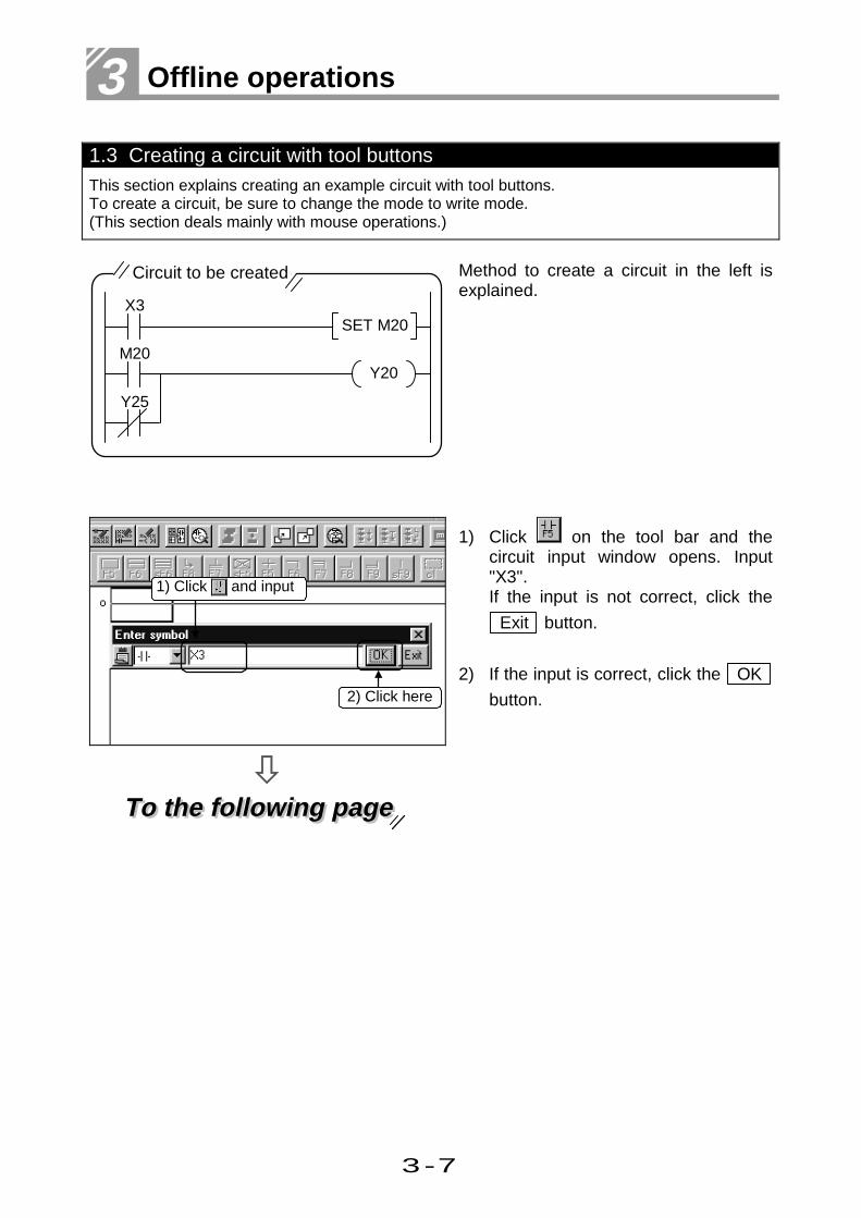
1.3 Creating a circuit with tool buttonsThis section explains creating an example circuit with tool buttons.To create a circuit, be sure to change the mode to write mode.(This section deals mainly with mouse operations.)
X3SET M20
Y25
M20Y20
Circuit to be created Method to create a circuit in the left isexplained.
To the following pageTo the following page
1) Click on the tool bar and thecircuit input window opens. Input"X3".If the input is not correct, click the
Exit button.
2) If the input is correct, click the OK
button.2) Click here
1) Click and input

3-8
Creating a circuit - Chapter 1 -
From previous pageFrom previous page
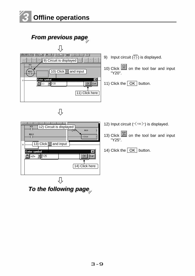
3) Input circuit (X3
) is displayed.
4) Click on the tool bar and input"SET M20".
5) Click the OK button.
To the following pageTo the following page
6) Input circuit ( SET M20 ) is displayed.
7) Click on the tool bar and input"M20".
8) Click the OK button.
6) Circuit is displayed
8) Click here
7) Click and input
3) Circuit is displayed
4) Click and input
5) Click here
3-9
3 Offline operations
From previous pageFrom previous page
9) Input circuit (M20
) is displayed.
10) Click on the tool bar and input"Y20".
11) Click the OK button.
To the following pageTo the following page
12) Input circuit ( Y20 ) is displayed.
13) Click on the tool bar and input"Y25".
14) Click the OK button.
9) Circuit is displayed
11) Click here
14) Click here
12) Circuit is displayed
13) Click and input
10) Click and input
3-10
Creating a circuit - Chapter 1 -
From previous pageFrom previous page
15) Input circuit (Y25
) is displayed.
16) Now, the circuit creation is complet-ed.
Conversion is required after creationof a circuit.
Part 3, 1.4.
15) Circuit is displayed
16) Circuit creation is completed

3-11
3 Offline operations
1.4 Converting a created circuitThis section explains converting a created circuit (program).
1) Click the window for the circuit to beconverted and make it active.
2) Click on the tool bar.Now, conversion is complete.
Short cut
keyF4
If an error occurs during conversion, thefaulty area on the circuit turns gray.Check the circuit.
1) Make the window active
2) Click here

3-12
• • • • • • • • • • 1• •

3-13
3 Offline operations
1.5 Creating a program with list commandsThis section explains creating the programs described in 1.2 and 1.3 with list commands.Be sure to set the operation to the write mode before program creation.
List to be created
LD X3SET M20LD M20ORI Y25OUT Y20END
Operations for creating a list as shownto the left are explained.
1) Click the button to switch to thelist display.
To the following pageTo the following page
2) Input "LD X3".Press the Esc Key if input is wrong.
3) After inputting correctly, press theEnter key.
1) Click here
2) Input here
3) Press Enter key

3-14
Creating a circuit - Chapter 1 -
From previous pageFrom previous page
4) Input "SET M20".
5) Press the Enter key.
6) Input "LD M20".
7) Press the Enter key.
8) Input "ORI Y25".
9) Press the Enter key.
10) Input "OUT Y20".
11) Press the Enter key.Now, programming with list comma-nds is complete.
7) Press the Enter key
9) Press the Enter key
11) Press the Enter key10) Input here
5) Press the Enter key4) Input here
6) Input here
8) Input here

3-15
3 Offline operations
1.6 Saving a created project
The created programs, comments and parameters are saved by project.This section explains saving created projects.
——Saving a new project or overwriting a project——
1) Click on the tool bar.
Short cut
keySCtrl
For overwriting, this completes thesaving operation.
(For saving a new project only) 2) Designate the folder where theproject is to be stored.
3) Set the project name.
4) Set a heading as required.
5) After setting the items, click the
Save button.
For more details of designating methodof the project, see···
Part 2, 2.4.
6) Click Yes button. Now, saving is
completed.
1) Click here
2) Designate the folder wherethe project is to be stored
3) Set the project name
4) Set a heading(Any)
5) Click here
6) Click here

3-16
Creating a circuit - Chapter 1 -
——Saving a new project or overwriting a project——
1) Click [Project]-[Save as] on themenu.
2) Designate the folder where theproject is to be stored.
3) Set the project name.
4) Set a heading as required.
5) After setting the items, click the
Save button.
For more details of designating methodof the project, see···
Part 2, 2.4.
6) Click Yes button. Now, saving is
completed.
1) Click here
2) Designate the folder wherethe project is to be stored
3) Set the project name
4) Set a heading(Any)
5) Click here
6) Click here

3-17
3 Offline operations
1.7 Reading a saved projectThis section explains reading a created project.
1) Click on the tool bar.
Short cut
keyCtrl O
2) Designate folder where the project isstored.
3) Click the project to read.
4) Click the Open button to read the
designated project.
For more details of designating methodof the project, see···
Part 2, 2.4.
1) Click here
4) Click here
2) Designate the folder where theproject is stored
3) Click here

3-18
Creating a circuit - Chapter 1 -
——The dialog box is displayed in the following cases——
(If another project is opened and saved) Yes ........ Ends the already open pro-
ject and reads the specifiedproject.
No .......... Continues the open project.
If another project is openedwithout circuit conversion Yes ........ Ends the project without
conversion.
No .......... Continues the open project.(Continues editing of thecircuit.)
If another project isopened and not saved Yes ........ Saves the open project,
then opens the specifiedproject.
No .......... Opens the specified projectwithout saving the openproject.
Cancel ... Continues the open projectas it is.(Does not read the specifi-ed project.)

3-19
3 Offline operations
Editing (cut, copy, paste) is indispensable for circuit creation.
This chapter explains editing operations that are important for circuit creation.
Be sure to switch to write mode before editing circuits.
2 Editing a circuit
2.1 Correcting part of a circuitThis section explains correcting part of a circuit.
Circuit to be edited
X3RST M20
SET M20
Y25
M20Y20
This section explains operations forediting part of circuit shown on the left.(SET M20→RST M20)
To the following pageTo the following page
1) Confirm that “Ovrwrte” is displayedat the lower right of the screen.
If “Insert” is displayed, press the Ins key to change the display to “Ovrwrte.”If “Insert” is displayed, a contact or acoil is added to the circuit.
<If you try to change X3 to X5>
X5 X3This part is added.
<If you try to change SET to RST>
This part is added.
SET M3
RST M3
1) Confirm
3-20
Editing a circuit - Chapter 2 -
From previous pageFrom previous page
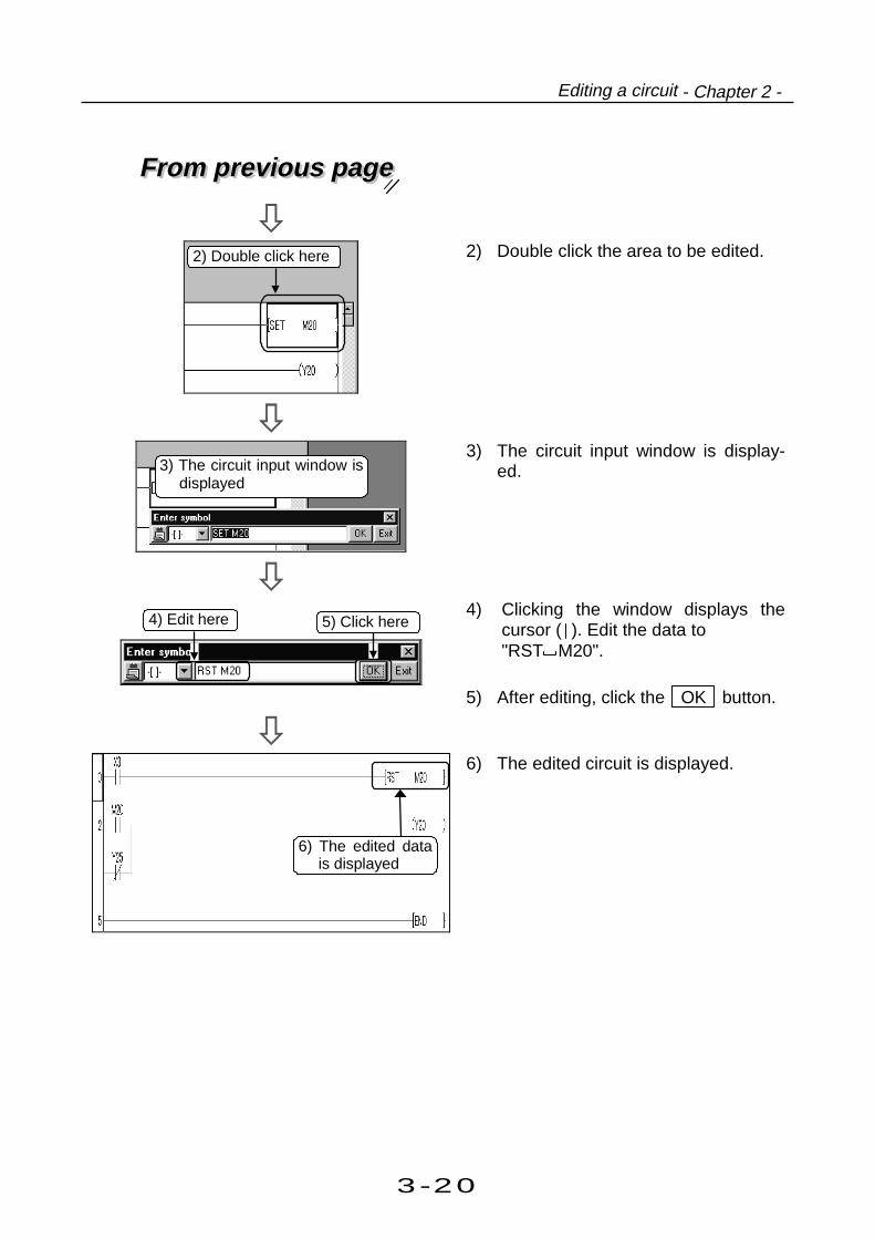
2) Double click the area to be edited.
3) The circuit input window is display-ed.
4) Clicking the window displays thecursor ( ). Edit the data to"RST M20".
5) After editing, click the OK button.
6) The edited circuit is displayed.
2) Double click here
3) The circuit input window isdisplayed
4) Edit here 5) Click here
6) The edited datais displayed

3-21
3 Offline operations
2.2 Cutting and copying a circuit blockThis section explains operations for cutting and copying a circuit block.
SET Y6
RST Y6
SET M111
M110
X6
5
0M111 M112 M113
Circuit block to be cut or copied This section explains operations forcutting and copying the circuit blockshown on the left.
1) Click the step number of the circuitblock to be cut or copied, and movethe cursor.
To the following pageTo the following page
2) Drag the mouse vertically to desig-nate the range to be cut or copied.The designated area is highlighted.
To designate a single-line circuit block,drag horizontally for easier rangedesignation.
2) Drag and designaterange
Area to be cut or copied
1) Click here and movethe cursor

3-22
Editing a circuit - Chapter 2 -
From previous pageFrom previous page
To cut the circuit : Go to 3).To copy the circuit : Go to 4) to 7).
(To cut the circuit) 3) Click on the tool bar. The circuitin the designated range is cut. Aftercutting, the remaining circuits areshifted upward to fill the vacancy.
Short cut
keyCtrl X
(To copy the circuit)
To the following pageTo the following page
4) Click on the tool bar.
Short cut
keyCtrl C
3) Click to executecutting
4) Click

3-23
3 Offline operations
From previous pageFrom previous page
5) Click (anywhere) on the circuit blockunder the line to be pasted with thecopied block.
• The circuit block is inserted abovethe cursor position.
• The circuit block cut or copied arealways inserted when pasted.To overwrite, delete the line to beoverwritten before pasting.
Part 3, 2.3.
To the following pageTo the following page
6) Click on the tool bar.
Short cut
keyCtrl V
6) Click here
The copied circuit block is inserted above thiscircuit block
5) Click here andmove the cursor

3-24
Editing a circuit - Chapter 2 -
From previous pageFrom previous page
7) The copied circuit block is pasted.
7) Copying is completed

3-25
3 Offline operations
2.3 Inserting or deleting a lineThis section explains operations for inserting or deleting a line.
1) Click (anywhere) on the line to beinserted or deleted, and move thecursor.
The line is inserted above the cursorline.
2) Right-click on the circuit creationscreen to display the menu.
To inset a line, go to 3).To delete a line, go to 5).
To the following pageTo the following page
2) Menu isdisplayed
1) Click here and movethe cursor

3-26
Editing a circuit - Chapter 2 -
From previous pageFrom previous page
(To insert a line) 3) Click the [Insert line] menu.
Short cut
keyShift Ins
4) A line is inserted above the cursorline.
(To delete a line) 5) Click the [Delete line] menu.
Short cut
keyShift Del
6) A line is deleted at the cursor.
4) A line has been inserted
5) Click here
6) A line has been deleted
3) Click here

3-27
3 Offline operations
2.4 Creating and deleting a ruled lineThis section explains creating or deleting a ruled line.
——Creating a ruled line——
1) Click on the tool bar.
Short cut
key
GPPQ and MEDOC Keys
GPPA Key
F10
Alt F10
2) Drag the mouse from the startposition to the end position.
Vertical ruled lines are created onthe left of the cursor.
3) Release the left mouse button.Ruled lines are created.
The "END" line cannot be deleted.
2) Drag
3) Creation completed
1) Click here

3-28
Editing a circuit - Chapter 2 -
——Deleting a ruled line——
1) Click on the tool bar.
Short cut
keyF9Alt
2) Drag the mouse from the startposition to the end position.
3) Release the left mouse button.Deletion is completed.
The "END" line cannot be deleted.
2) Drag
3) Deletion completed
1) Click here

3-29
3 Offline operations
3.1 Searching with a designated deviceThis section explains operations for searching circuits for the designated device name.
1) Right-click on the circuit creation
screen, or click on the tool bar.
2) Click the [Find device] menu.(Not required when operating fromthe tool bar.)
To the following pageTo the following page
3) Input the device name to search.
4) Set the find direction.
Find direction• "From top to bottom"
Searches from the 0 step to the ENDcommand.
• "From cursor to bottom"Searches from the cursor position tothe END command.
• "From cursor to top"Searches from the cursor position tothe 0 step.
1) Right-click here
3) Input the device nameto search (e.g. X3)
4) Set the search direction
2) Click here
This operation quickly finds circuits to be edited,debugged,or monitored.
3 Searching a circuit

3-30
Searching a circuit - Chapter 3 -
From previous pageFrom previous page
5) Click the Find Next button.
6) Starts searching.The cursor moves to the circuitfound first.
Every time the Find Next button isclicked, the cursor moves to circuitswith the designated device name oneafter another.
7) If there is no circuit with the design-ated device name in the followingsteps, a dialog box to notice the endof search is displayed.
Click the OK button.
8) Click the Close button.
Now, operations for searching devic-es are completed.
Find option• "Digit"
If the searched device is designatedas "X1", "K4X0" of "M0V K4X0 D0" issearched because it contains devices"X0 to X7".
• "Double word"If the search device is designated as"D1", "D0" of "DMOV D0 R0" issearched because it contains bothdevices of D0 and D1.
5) Click here
7) Click here
8) Click here
6) Searching starts

3-31
3 Offline operations
3.2 Searching with a step No.This section explains operations for displaying the step of the designated number on the screen.
1) Input the step number to be display-ed.
For searching with step No., nooperation is required to display menu.Inputting a step No. automaticallydisplays the Step No. Search window.
2) Press the Enter key.
3) The circuit of the designated stepnumber is displayed.
To continue searching a step number,repeat the above procedures.
2) Input the Enter key
3) Designated step is displayed
1) Input step No. here

3-32
3 Offline operations

3-33
3 Offline operations
4.1 Replacing with a designated deviceThis section explains replacing a device in a circuit with the designated device.
1) Click the [Find/Replace]-[Replacedevice] menu.
2) Input the name of the device to bereplaced (old device name).
To the following pageTo the following page
3) Input a device name after replace-ment (new device name).3) Input a new device name
(e.g. X40)
1) Click here
2) Input device name(e.g. X80)
This chapter explains replacing a circuit device or command with the designated device
or command.
Be sure to set the operation to the write mode before replacing circuit .
4 Replacing within a circuit

3-34
Replacing within a circuit - Chapter 4 -
From previous pageFrom previous page
4) Input the number of points to bereplaced from the old device.The number of points can be set indecimal or hexadecimal.
Example of setting number of points forreplacementOld device: X0, New device: X20Number of points for replacement: 3
X0 X20X1 X21X2 X22
Three devices from X0 will be replaced.
To the following pageTo the following page
5) Set the find direction.
Find direction• From top to bottom
Searches from 0 step to ENDcommand.
• From cursor to bottomSearches from the cursor position toEND command.
• Specified rangeSearches within the designated steprange.
Put a check mark if commentsare also changed
5) Set the find direction
4) Input the number of points tobe replaced (e.g. 1)

3-35
3 Offline operations
From previous pageFrom previous page
6) Click the Replace button.
To replace the old devices in the cir-cuit with the new devices in a batch,
click the Replace all button.
7) The cursor is displayed on the circuitfound first (X80).
The first click on the Replace button does not replace the characterstring but searches the old string.Next click on the Replace buttonexecutes replacement of the searchedcharacter string.
To the following pageTo the following page
8) Click the Replace button.
To search the next device withoutreplacement, click the Find Nextbutton.
6) Click here
Click for batch replacement
8) Click here
7) The searchedcircuit is displayed

3-36
Replacing within a circuit - Chapter 4 -
From previous pageFrom previous page
9) X80 of step 33 is changed to X40,and the cursor moves to the next olddevice (X80).
10) Click the Replace button.
11) X80 of step 36 is changed to X40,and the cursor moves to the next olddevice (X80).
Every time the Replace button isclicked, old device names are changedto the new device names one afteranother.
12) If there is no old device name in thefollowing steps, a dialog box tonotice the end of search is display-ed.
Click the OK button.
13) Click the Close button.
Now, operations for replacing dev-ices are completed.
13) Click here
12) Click here
9) Changed to X40
10) Click here
11) Changed to X40

3-37
3 Offline operations
4.2 Replacing open contact with close contact and vice versaThis section explains replacing open contact in the circuit to close contact and vice versa.
1) Click the [Find/Replace]-[Changeopen/close contact] menu.
2) Input the device name to bereplaced (old device name).
3) Input the number of points to bereplaced from the old device.The number of points can be set indecimal or hexadecimal.
Example of setting number of pointsfor replacementDevice: X0, Number of points forreplacement: 3X0, X1 and X2 (three points) will bereplaced for A to B contact.
To the following pageTo the following page
4) Set the find direction.
Find direction• From top to bottom
Searches from 0 step to ENDcommand.
• From cursor to bottomSearches from the cursor position toEND command.
• Specified rangeSearches within the designated steprange.
1) Click here
3) Input the number ofreplacement (e.g. 1)
2) Input device name(e.g. X80)
4) Set the search direction

3-38
Replacing within a circuit - Chapter 4 -
From previous pageFrom previous page
5) Click the Replace all button.
By clicking the Replace button,
AB contacts can be replaced whilesearching the device name.
6) Contacts of the designated devicename are replaced.If a device name of open contact( ) is designated, the contact isreplaced with close ( ) contact.If a device name of open branch( ) is designated, the contact isreplaced with close ( ) branchcontact.
7) After completing open/close contactreplace-ment, a dialog box isdisplayed to notice completion.
Click the OK button.
8) Click the Close button.
Now, operations for replacing opencontact with close contact and viceversa are completed.
7) Click here
8) Click here
6) Replacement completed
Part 3, 4.1.
Click here to replacewhile searching
5) Click here

3-39
3 Offline operations
What is a device comment?A device comment describes each device of the created circuit so that the application of eachdevice can be viewed on the circuit creation screen.A device comment can include up to 32 characters for a device.
When creating a comment, tiling the circuit creation screen and the comment creation screenallows creating a device comment while referring to the device used in the created circuit.
Part 2, 2.5.
This chapter explains the following :
Creating device comments to describe meaning and application of each device Creating statements to describe the operation of the circuit block Creating notes to describe the coil and the application instruction
5 Explaining circuit components
3-40
Explaining circuit components - Chapter 5 -
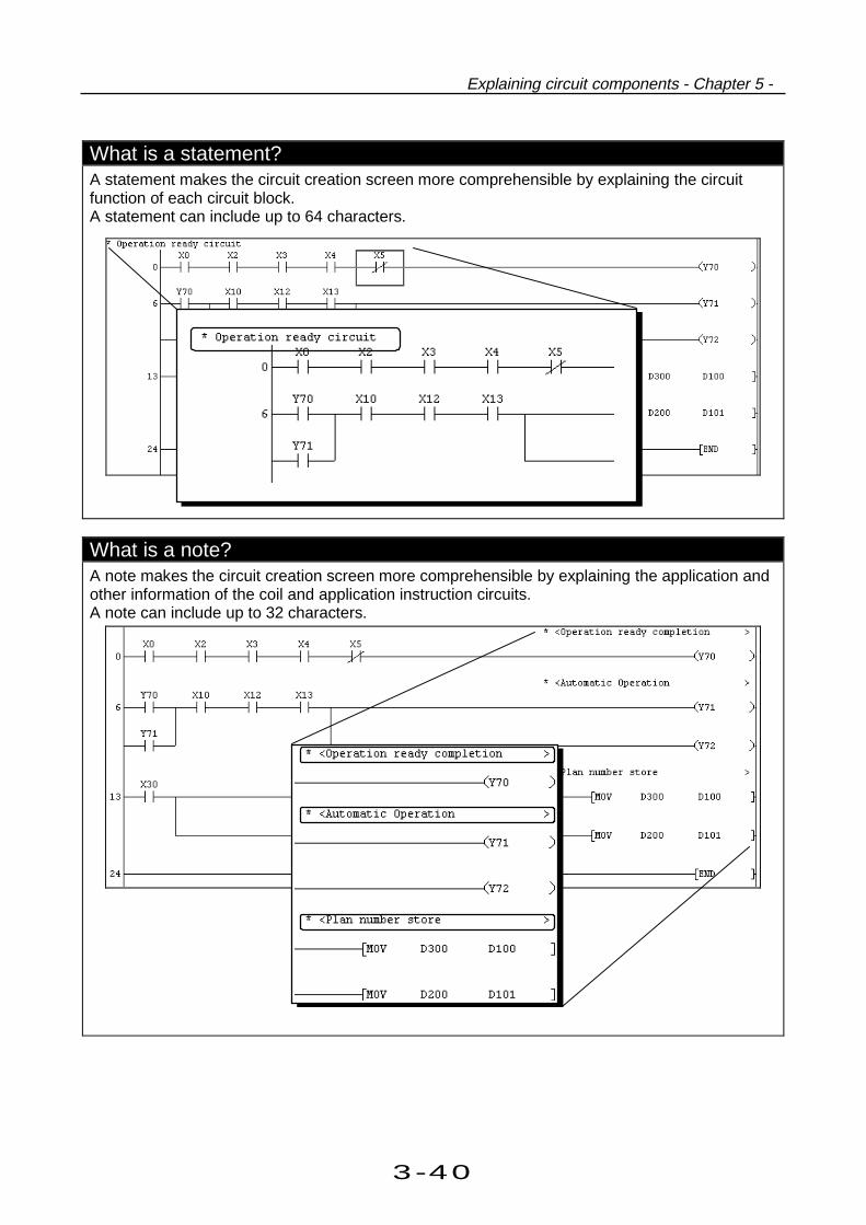
What is a statement?A statement makes the circuit creation screen more comprehensible by explaining the circuitfunction of each circuit block.A statement can include up to 64 characters.
What is a note?A note makes the circuit creation screen more comprehensible by explaining the application andother information of the coil and application instruction circuits.A note can include up to 32 characters.

3-41
3 Offline operations
What are an embedded statement and an embedded note (can be set whenQnACPU or QCPU is used)?A character string set in an embedded statement or embedded note is handled as part of asequence program. Therefore, performing write to PLC writes it to the PLC CPU automaticallyand performing read from PLC reads it automatically.Embedded statements and embedded notes are very useful because merely executing readfrom PLC sets statements and notes.It should be noted that the number of steps will be consumed in proportion to the number ofcharacters used.(A space is also handled as one character.)
<Number of consumed steps>
2+number of characters
2 steps (Fractional portion is rounded down)
Write to PLC
PLC
Program
Statements,notes
Read from PLC
Program
Statements,notes
GPPW GPPW
What are a separate statement and a separate note?A character string set in a separate statement or separate note is controlled only on GPPW.Therefore, the statements and notes are not written to the PLC if write to PLC is performed.A character string set in a separate statement or separate note is headed by "*".
Program
Write to PLC
PLC
Program
Statements,notes
Read from PLC
GPPW GPPW

3-42
Explaining circuit components - Chapter 5 -

3-43
3 Offline operations
5.1 Creating device commentsThis section explains creating comments for designated devices.There are two kinds of comments: the "common comment" (one comment per project)and the "program comment" (one comment per program).Here, the common comment is described.
1) Click the + mark of [Device comm-ent] in the project data list.
To the following pageTo the following page
2) Double click [COMMENT] (commoncomment).
If the comment is to include 17characters or more, click the [Tools] -[Options] set the number of charactersfor display to 32.
Set to 32
1) Click here
2) Double click here

3-44
Explaining circuit components - Chapter 5 -
From previous pageFrom previous page
3) The comment creation screen isdisplayed.Input the device name for which acomment is created.
4) Click the Display button.
5) The device name is displayed fromM0.Double click the comment columnnext to the device name to which acomment is input.
The cursor ( ) can be moved bypressing ↓ , ↑ , → , and ←keys.
To the following pageTo the following page
6) Input the comment to the designateddevice name, then press the Enterkey.A comment can include up to 32characters .To correct the input comment, pressBS or Del key and re-input.
Comments can be created byWindows applications.
Part 5, Chapter 2.
Part 3, 6.1.
5) Double click here
6) Input comment, then pressthe Enter key.(e.g. "Switch 1")
3) Input device name(e.g. M0)
4) Click here
3-45
3 Offline operations
From previous pageFrom previous page
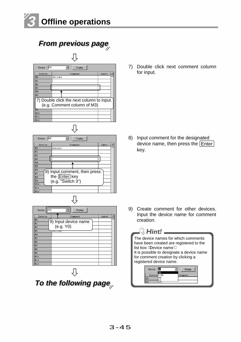
7) Double click next comment columnfor input.
8) Input comment for the designateddevice name, then press the Enterkey.
To the following pageTo the following page
9) Create comment for other devices.Input the device name for commentcreation.
The device names for which commentshave been created are registered to thelist box Device nameIt is possible to designate a device namefor comment creation by clicking aregistered device name.
7) Double click the next column to input.(e.g. Comment column of M3)
9) Input device name(e.g. Y0)
8) Input comment, then pressthe Enter key(e.g. "Switch 3")

3-46
Explaining circuit components - Chapter 5 -
From previous pageFrom previous page
10) Click the Display button.
11) The device name is displayed fromY0.Click the comment column and inputcomment.
12) Confirm the created comment on thecircuit creation screen.Click the [View]-[Comment] menu.
13) The comment created for the deviceis displayed.
13) Comment is displayed here
11) Input comment, then pressthe Enter key
12) Click here
10) Click here
3-47
3 Offline operations
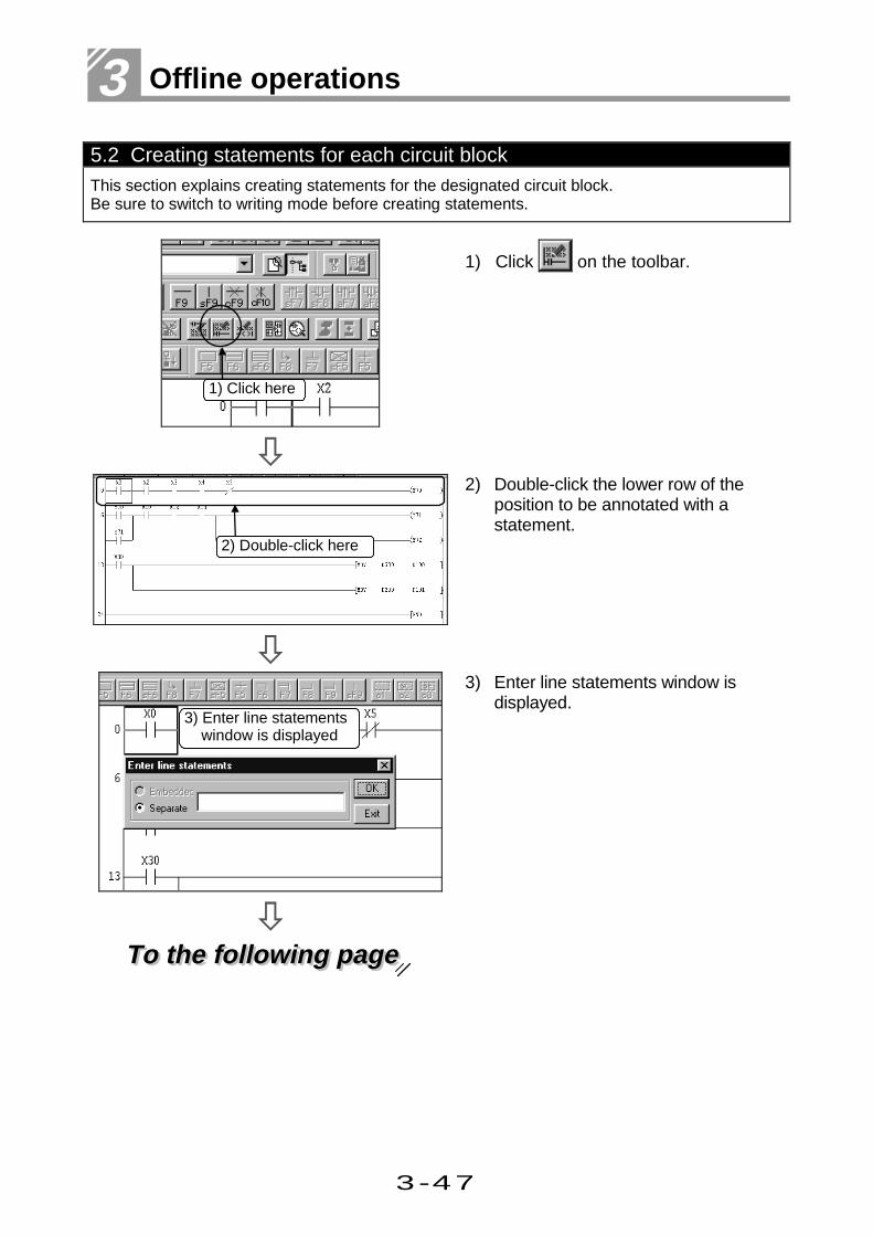
5.2 Creating statements for each circuit blockThis section explains creating statements for the designated circuit block.Be sure to switch to writing mode before creating statements.
1) Click on the toolbar.
2) Double-click the lower row of theposition to be annotated with astatement.
To the following pageTo the following page
3) Enter line statements window isdisplayed.
1) Click here
2) Double-click here
3) Enter line statements window is displayed

3-48
Explaining circuit components - Chapter 5 -
From previous pageFrom previous page
4) Enter the statement.Any statement can be up to 64characters long.To correct the statement onceentered, press the BS and Delkeys and enter the statement again.
5) Click the OK button.
6) Check the created statement on thecircuit creation screen.Click the [View]-[Statement] menu.
F7Ctrl
7) The created statement appears.
6) Click here
5) Click here
7) Statement is displayed here
Part 3, 6.5.
4) Input statement.(e.g. "Operation ready circuit")

3-49
3 Offline operations
5.3 Creating a note for coil and application instructionThis section explains creating a note for the designated coil and application instruction.Be sure to switch to writing mode before creating a note.
1) Click on the toolbar.
2) Double-click the position of a coil orapplication instruction to be annotat-ed with a note.
To the following pageTo the following page
3) The Enter note window appears.
3) Enter note window is displayed
2) Double click here
1) Click here
3-50
Explaining circuit components - Chapter 5 -
From previous pageFrom previous page
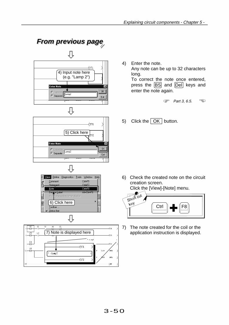
4) Enter the note.Any note can be up to 32 characterslong.To correct the note once entered,press the BS and Del keys andenter the note again.
5) Click the OK button.
6) Check the created note on the circuitcreation screen.Click the [View]-[Note] menu.
F8Ctrl
7) The note created for the coil or theapplication instruction is displayed.
Part 3, 6.5.
5) Click here
6) Click here
4) Input note here(e.g. "Lamp 2")
7) Note is displayed here

3-51
3 Offline operations
6.1 Correcting device comments
This section explains correcting comments for the designated device.
1) Double click the comment to becorrected in Device comment shown in the project data list.
2) The comment creation screen isdisplayed.Use the Device list box to set thedevice name to be corrected.
To the following pageTo the following page
3) Click the Display button.
1) Double click here.(e.g. "COMMENT" will be corrected.)
3) Click here
2) Set the device name to becorrected. (e.g. Select M0.)
This chapter explains how to edit (correct,delete,copy) the device comment , the statement
and the note for the device comment.
6 Editing comments

3-52
Editing comments - Chapter 6 -
From previous pageFrom previous page
4) Double click the comment column tobe corrected.
5) A cursor ( ) is displayed.Correct the comment.
Use the following keys for correctingcomment.• Move cursor: → and ← keys• Delete characters at the left of the
cursor: BS key• Delete all: Del key
After correcting the comment, pressthe Enter key.
5) Correct the comment
4) Double click here(e.g. M3 will be corrected.)

3-53
3 Offline operations
6.2 Deleting (cutting) device comments
This section explains deleting (cutting) the device comment for the designated device.
——Deleting (cutting) each comment——
1) Double click the comment to bedeleted (cut) in the project data list.
To the following pageTo the following page
2) The comment creation screen isdisplayed.Click the comment column to delete(cut), and move the cursor.
1) Double click here ("COMMENT" iscorrected as an example.)
2) Click here (e.g. X5)
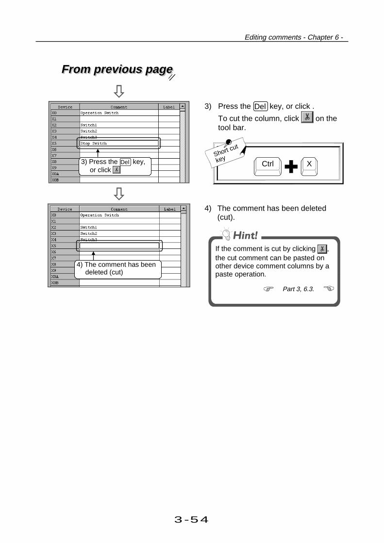
3-54
Editing comments - Chapter 6 -
From previous pageFrom previous page
3) Press the Del key, or click .
To cut the column, click on thetool bar.
Short cut
keyXCtrl
4) The comment has been deleted(cut).
If the comment is cut by clicking ,the cut comment can be pasted onother device comment columns by apaste operation.
Part 3, 6.3.
4) The comment has beendeleted (cut)
3) Press the Del key,or click

3-55
3 Offline operations
——Deleting (cutting) a series of comments in batch——
1) Double click comment to becorrected in Device commentshown in the project data list.
2) The comment creation screen isdisplayed.Click the top of the commentcolumns to be deleted (cut), andmove the cursor.
To the following pageTo the following page
3) Confirm that the cursor ( ) isdisplayed, and drag the range to bedeleted (cut).
1) Double click here(e.g. "COMMENT" will be copied.)
2) Click the top commentcolumn (e.g. X2)
3) Drag the columns to bedeleted (e.g. X2 to X5)

3-56
Editing comments - Chapter 6 -
From previous pageFrom previous page
4) The comment columns in thedragged area are highlighted (exceptfor the top column).To redo the range specification, clickany comment column.To delete the columns, press theDel key.
To cut the columns, click on thetool bar.
Short cut
keyXCtrl
5) Now the designated comments havebeen all deleted (cut).
If the comment is cut by clicking ,the cut comment can be pasted onother device comment columns by apaste operation.
Part 3, 6.3.
4) Columns are highlighted
5) Comments have beendeleted (cut)

3-57
3 Offline operations
6.3 Copying device commentsThis section explains copying comments for the designated device.
1) Double click the comment to becopied in COMMENT shown in theproject data list.
2) The comment creation screen isdisplayed.Click the top of the commentcolumns to be copied, and move thecursor.
To the following pageTo the following page
3) Confirm that the cursor ( ) isdisplayed, and drag the range to becopied.
1) Double click here(e.g. "COMMENT" will be copied.)
2) Click the top commentcolumn. (e.g. X2)
3) Drag the columns to becopied. (e.g. X2 to X5)

3-58
Editing comments - Chapter 6 -
From previous pageFrom previous page
4) The comment columns in thedragged area are highlighted.To redo the range specification, clickany comment column.Click on the tool bar.
Short cut
keyCtrl C
5) Click the top column for pastingcomments, and move the cursor.
6) Confirm that the cursor ( ) isdisplayed, and click on the toolbar.
Short cut
keyCtrl V
7) Now, the comments have beenpasted to the area from thedesignated column.
4) Click
6) Click
5) Click the top comment column.(e.g. X7)
7) The comment columns havebeen pasted here
4) Click

3-59
3 Offline operations
6.4 Searching statements and notesThis section explains searching circuits with the designated statement and note.Display statements and notes on the circuit creation screen before searching for them.
1) Click the [View]-[Statement], [Note]menu.Statements and notes are displayedon the circuit creation screen.
2) Right click on the circuit creationscreen, or click on the tool bar.
To the following pageTo the following page
3) Click the [Find character string]menu. (Not required when operatingfrom the tool bar.)
2) Right click here
1) Click here
3) Click here

3-60
Editing comments - Chapter 6 -
From previous pageFrom previous page
4) Input statement or note to search.
5) Set the find direction.
Find direction• From top to bottom
Searches from 0 step to the ENDcommand.
• From cursor to bottomSearches from the cursor position toEND command.
• From cursor to topSearches from the cursor position to 0step.
6) Click the Find Next button.
7) Searching starts.The cursor moves to the circuitfound first.
Every time the Find next button isclicked, the cursor moves to circuits withthe designated character string one afteranother.
8) If there is no circuit with thedesignated character string in thefollowing steps, a dialog box tonotice the end of search is displayed.Click the OK button.
9) Click the Close button.Now, operation for searchingcharacter strings are completed.
9) Click here
8) Click here
5) Set search direction
4) Input character string here(e.g. Operation)
6) Click here
7) Search starts

3-61
3 Offline operations
6.5 Correcting statements and notesThis section explains correcting statements and notes.Display statements and notes on the circuit creation screen before correcting them so that theareas for correction can be easily checked.
1) Click the [View]-[Statement], [Note]menu.Statements and notes are displayedon the circuit creation screen.
2) Click on the tool bar to switch towrite mode.
Short cut
keyF2
To the following pageTo the following page
3) Click either of the following buttonson the toolbar.• To correct a statement :
• To correct a note :
3) Click here
1) Click here
2) Click here
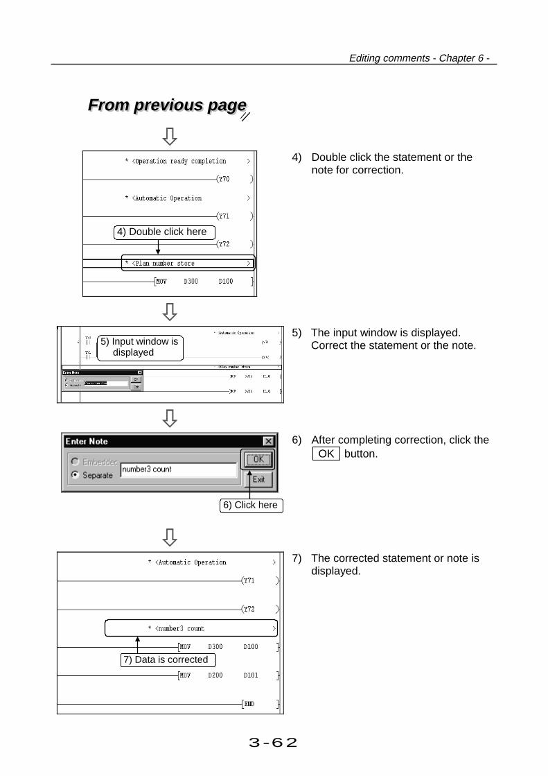
3-62
Editing comments - Chapter 6 -
From previous pageFrom previous page
4) Double click the statement or thenote for correction.
5) The input window is displayed.Correct the statement or the note.
6) After completing correction, click the OK button.
7) The corrected statement or note isdisplayed.
5) Input window isdisplayed
4) Double click here
7) Data is corrected
6) Click here
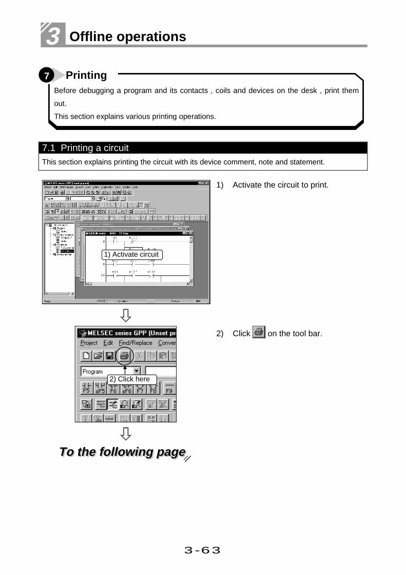
3-63
3 Offline operations
7.1 Printing a circuitThis section explains printing the circuit with its device comment, note and statement.
1) Activate the circuit to print.
To the following pageTo the following page
2) Click on the tool bar.
1) Activate circuit
2) Click here
7 PrintingBefore debugging a program and its contacts , coils and devices on the desk , print them
out.
This section explains various printing operations.
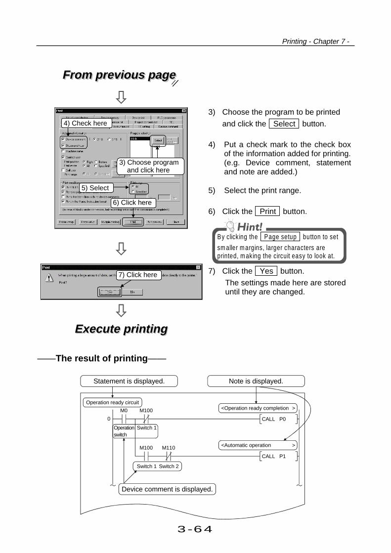
3-64
Printing - Chapter 7 -
From previous pageFrom previous page
3) Choose the program to be printed
and click the Select button.
4) Put a check mark to the check boxof the information added for printing.(e.g. Device comment, statementand note are added.)
5) Select the print range.
6) Click the Print button.
By clicking the Page setup button to set
sm aller m argins, larger characters areprinted, m aking the circuit easy to look at.
Execute printingExecute printing
7) Click the Yes button.
The settings made here are storeduntil they are changed.
——The result of printing ——
M0 M100
M100 M110
CALL P0
CALL P1
0
Operationswitch
Switch 1
Switch 1 Switch 2
<Automatic operation
<Operation ready completionOperation ready circuit
>
>
Device comment is displayed.
Statement is displayed. Note is displayed.
6) Click here
5) Select
4) Check here
3) Choose programand click here
7) Click here

3-65
3 Offline operations
7.2 Printing contacts or coils in useThis section explains printing the circuit contacts and coils in use.
1) Click on the tool bar.
To the following pageTo the following page
2) Click the "Cross reference list" tab.
1) Click here
2) Check here

3-66
Printing - Chapter 7 -
From previous pageFrom previous page
3) Choose the program to be printed
and click the Select button.
4) Check that a check mark is put to theContact user and Coil user checkboxes.(To print both contact and coil usagelists.)
5) Designate the print range.
6) Click the Print button.
Execute printingExecute printing
7) Click the [Yes] button.The settings made here are storeduntil they are changed.
6) Click here
4) Check here
5) Select
3) Choose program and click here
7) Click here

3-67
3 Offline operations
7.3 Printing the device in useThis section explains printing the circuit device.
1) Click on the tool bar.
To the following pageTo the following page
2) Click the "List of used device" tab.
1) Click here
2) Click here

3-68
Printing - Chapter 7 -
From previous pageFrom previous page
3) Choose the program to be printed
and click the Select button.
4) Click the Print button.
Additional informationAdditional items to be printed otherthan contacts or coils are set here.
Print conditionsSet for printing only the devices usedin the program.
Print rangeDesignates the program range forprinting.
Program selectionProgram is selected for printing.
Execute printingExecute printing
5) Click the Yes button.
The settings made here are storeduntil they are changed.
4) Click here
3) Choose program and click here
5) Click here

3-69
3 Offline operations
7.4 Printing a list of device comments in useThis section explains printing a list of device comments used in the following circuit.
This section explains printing a list of device comments used in the following
circuit.
Device comment list circuit
1) Click on the tool bar.
To the following pageTo the following page
2) Click the [Device comment] tab.
1) Click here
2) Click here
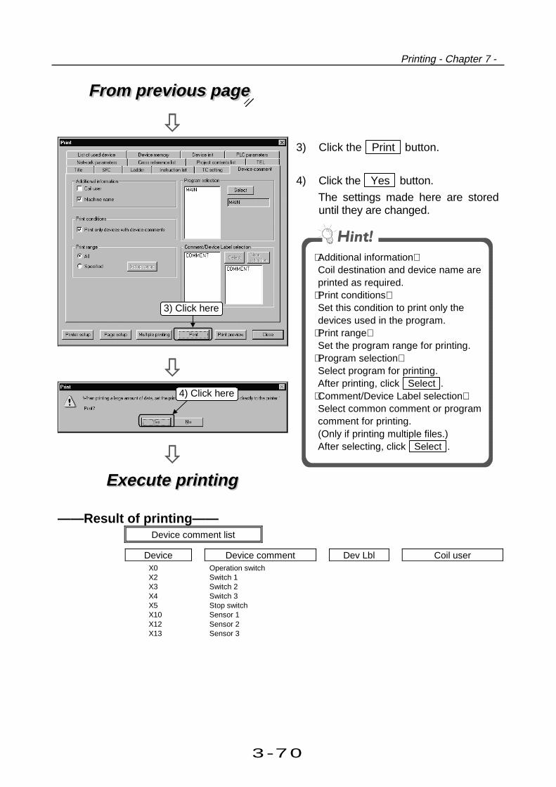
3-70
Printing - Chapter 7 -
From previous pageFrom previous page
Execute printingExecute printing
3) Click the Print button.
4) Click the Yes button.
The settings made here are storeduntil they are changed.
Additional informationCoil destination and device name areprinted as required.
Print conditionsSet this condition to print only thedevices used in the program.
Print rangeSet the program range for printing.
Program selectionSelect program for printing.After printing, click Select .
Comment/Device Label selectionSelect common comment or programcomment for printing.(Only if printing multiple files.)After selecting, click Select .
——Result of printing——Device comment list
Device Device comment Dev Lbl Coil userX0X2X3X4X5X10X12X13
Operation switchSwitch 1Switch 2Switch 3Stop switchSensor 1Sensor 2Sensor 3
3) Click here
4) Click here

3-71
3 Offline operations

Part 4
4
Online operations
1. Writing and reading to/from the PLC CPU1.1 Specifying the PLC CPU you want toaccess....................... 4- 1
1.2 Writing data to the PLC CPU .............................................. 4- 7
2. Monitoring PLC status2.1 Monitoring circuit status ...................................................... 4- 9
2.2 Monitoring designated device ............................................. 4-133. Debugging a created circuit3.1 Turning ON/OFF contact positively ..................................... 4-15
3.2 Executing a program step by step....................................... 4-174. Online change4.1 Online change of the PLC CPU .......................................... 4-19
4.2 Changing data during monitoring, and writing during a run ... 4-21
4

4-1
4 Online operations
Even if a circuit (program) is created by GPPW, the PLC does not work as a PLC if data
is not written to the CPU, or it cannot read the circuit (program) from the CPU for
debugging.
This chapter explains writing and reading the created circuit to/from the CPU.
1 Writing and reading to/from the PLC CPU
1.1 Specifying the PLC CPU you want to accessThis section describes operations to set the personal computer side interface, PLC CPU sideinterface, etc. when the personal computer and PLC CPU are connected.In this section, access is made to the PLC CPU (own station) which is connected from the serialport (COM port) of the personal computer by a conversion cable.
Connection image
COM port PLC CPU
1) Click the [Online]-[Transfer setup]menu.
To the following pageTo the following page
1) Click here

4-2
Writing and reading to/from the PLC CPU - Chapter 1 -
From previous pageFrom previous page
2) Click the Connection channel list
button.
3) Choose the connection channel to beused. Here, select "Serial port CPUunit connection".
After making selection, Click OK
button.
4) Double-click Serial of PC side I/F.
To the following pageTo the following page
2) Click here
4) Double-click here
3) Choose from list

4-3
4 Online operations
From previous pageFrom previous page
5) Set COM port and Baud rate.Here, choose "COM2" and "9.6Kbps".
6) Double-click CPU unit of PLC sideI/F.
7) Set the CPU mode of the PLC CPU tobe connected with GPPW.Here, choose "ACPU".
8) Double-click No specification ofOther station.
To the following pageTo the following page
5) Choose from list box
8) Double-click here
6) Double-click here
7) Choose "ACPU"

4-4
Writing and reading to/from the PLC CPU - Chapter 1 -
From previous pageFrom previous page
9) Set the time (seconds) to Check atcommunication time.
10) Click the System image button.
11) On the system image screen, checkwhether the settings are correct or not.
Clicking the OK button returns to the
Connection Setup screen.
To the following pageTo the following page
9) Set "5"
10) Click here
11) Check settings

4-5
4 Online operations
From previous pageFrom previous page
12) Click the Connection test button to
check whether the connection setup isactually correct.
13) The result of the communication testwith the PLC CPU appears.If communication failed, check theconnection setup, cable connections,etc.
14) When the setting is finished, click the
OK button.
13) Test result
12) Click here
14) Click here

4-6
Writing and reading to/from the PLC CPU - Chapter 1 -

4-7
4 Online operations
1.2 Writing data to the PLC CPU
This section explains writing circuits created by GPPW (sequence program) to CPU.Reading can also be performed using the same procedure.
1) The following explanation assumesthat the circuits (sequence programs)have already been created by GPPW.
2) Click the [Online]-[Write to PLC] menu.
3) On the File selection screen, choosethe file of the data to be written to thePLC CPU.
Here, click the Param+Prog button.
4) When the selected file is checked, click
the Execute button.
5) A dialog box for writing is displayed.When finished, the message
Completed appears. Click OK to
end writing.
2) Click here
4) Click here
3) Click here
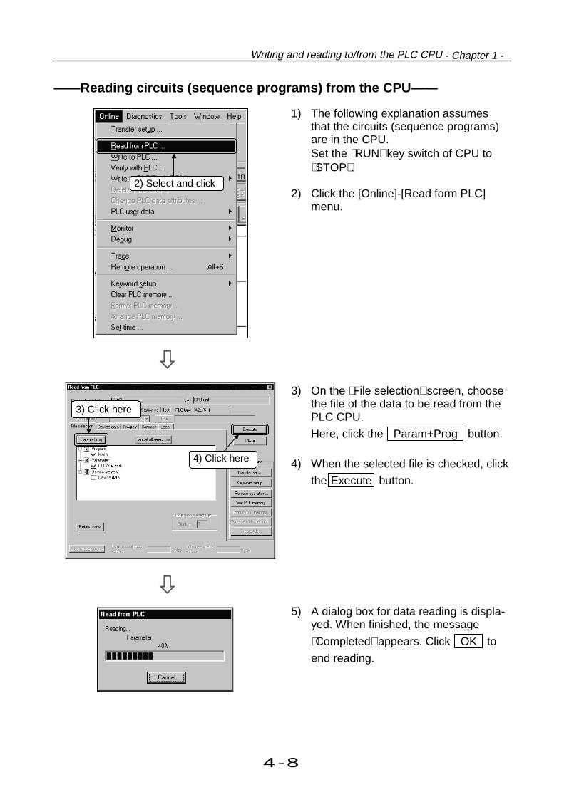
4-8
Writing and reading to/from the PLC CPU - Chapter 1 -
——Reading circuits (sequence programs) from the CPU——
1) The following explanation assumesthat the circuits (sequence programs)are in the CPU.Set the RUN key switch of CPU toSTOP.
2) Click the [Online]-[Read form PLC]
menu.
3) On the File selection screen, choosethe file of the data to be read from thePLC CPU.
Here, click the Param+Prog button.
4) When the selected file is checked, click
the Execute button.
5) A dialog box for data reading is displa-yed. When finished, the message
Completed appears. Click OK to
end reading.
4) Click here
2) Select and click
3) Click here

4-9
4 Online operations
Reads a circuit (sequence program) written to PLC CPU on GPPW and monitors its
operation status.
This chapter explains operations for monitoring.
2 Monitoring PLC status
2.1 Monitoring the circuit statusThis section explains operations to monitor the circuit (sequence program) status.Further, this section describes operations to register and monitor only the specified circuit blockout of a circuit which takes up more than one screen.
Assume that the same circuit (sequenceprogram) as on GPPW has been written tothe PLC CPU.
1) Click the [Online]-[Monitor]-[Monitor
mode] menu.
To the following pageTo the following page
2) Circuit monitoring starts.
1) Click here

4-10
Writing and reading to/from the PLC CPU - Chapter 1 -
From previous pageFrom previous page
3) To monitor distant circuit areas on onescreen, click the [Online]-[Monitor]-[Entry ladder monitor] menu.
To avoid overlapping the ladder monitorand entry ladder monitor screens, clickthe [Window]-[Tile vertically]/[Tilehorizontally] menu.The screens shownat bottom left are tiled vertically.
4) The entry ladder screen appears.
5) Register a circuit block by copying andpasting or dragging and dropping itfrom the ladder monitor screen to theentry ladder monitor screen.
In the same project, even adifferent program can be entered.The program name and stepnumber are indicated in the circuitblock.
6) Clicking the [Online]-[Monitor]-[Startmonitor] menu starts entry laddermonitoring.
3) Click here
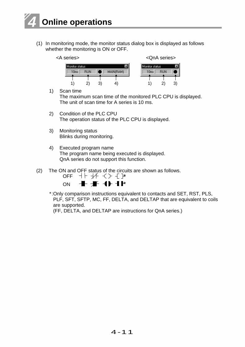
4-11
4 Online operations
(1) In monitoring mode, the monitor status dialog box is displayed as followswhether the monitoring is ON or OFF.
<A series> <QnA series>
1) Scan timeThe maximum scan time of the monitored PLC CPU is displayed.The unit of scan time for A series is 10 ms.
2) Condition of the PLC CPUThe operation status of the PLC CPU is displayed.
3) Monitoring statusBlinks during monitoring.
4) Executed program name
The program name being executed is displayed.QnA series do not support this function.
(2) The ON and OFF status of the circuits are shown as follows.
∗:Only comparison instructions equivalent to contacts and SET, RST, PLS,PLF, SFT, SFTP, MC, FF, DELTA, and DELTAP that are equivalent to coilsare supported.(FF, DELTA, and DELTAP are instructions for QnA series.)
4)3)2)1) 3)2)1)
OFF
ON
**

4-12
Monitoring PLC status - Chapter 2 -
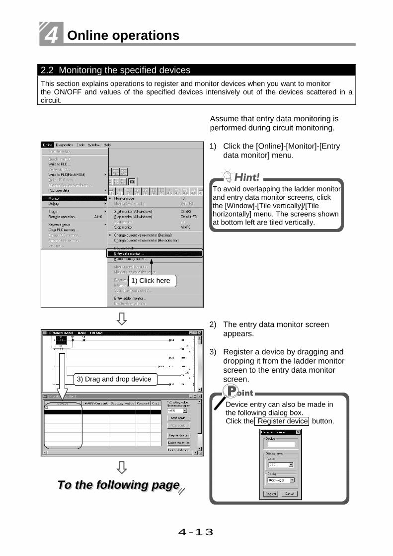
4-13
4 Online operations
2.2 Monitoring the specified devicesThis section explains operations to register and monitor devices when you want to monitorthe ON/OFF and values of the specified devices intensively out of the devices scattered in acircuit.
Assume that entry data monitoring isperformed during circuit monitoring.
To the following pageTo the following page
1) Click the [Online]-[Monitor]-[Entrydata monitor] menu.
To avoid overlapping the ladder monitorand entry data monitor screens, clickthe [Window]-[Tile vertically]/[Tilehorizontally] menu. The screens shownat bottom left are tiled vertically.
2) The entry data monitor screenappears.
3) Register a device by dragging anddropping it from the ladder monitorscreen to the entry data monitorscreen.
Device entry can also be made inthe following dialog box.Click the Register device button.
1) Click here
3) Drag and drop device
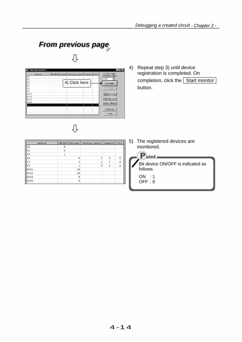
4-14
Debugging a created circuit - Chapter 2 -
From previous pageFrom previous page
4) Repeat step 3) until deviceregistration is completed. On
completion, click the Start monitor
button.
5) The registered devices aremonitored.
Bit device ON/OFF is indicated asfollows.
ON : 1OFF : 0
4) Click here
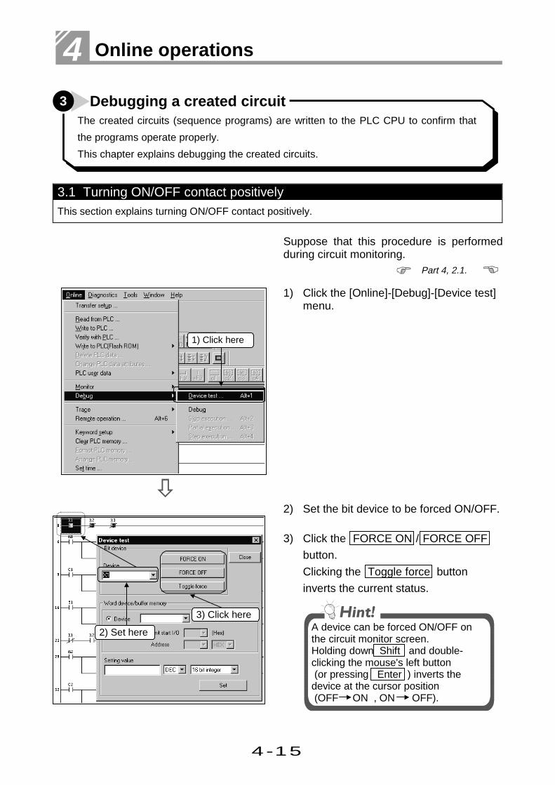
4-15
4 Online operations
The created circuits (sequence programs) are written to the PLC CPU to confirm that
the programs operate properly.
This chapter explains debugging the created circuits.
3 Debugging a created circuit
3.1 Turning ON/OFF contact positivelyThis section explains turning ON/OFF contact positively.
Suppose that this procedure is performedduring circuit monitoring.
1) Click the [Online]-[Debug]-[Device test]menu.
2) Set the bit device to be forced ON/OFF.
3) Click the FORCE ON / FORCE OFF
button.
Clicking the Toggle force button
inverts the current status.
A device can be forced ON/OFF onthe circuit monitor screen.Holding down Shift and double-clicking the mouse's left button (or pressing Enter ) inverts thedevice at the cursor position (OFF ON , ON OFF).
1) Click here
3) Click here
Part 4, 2.1.
2) Set here

4-16
Debugging a created circuit - Chapter 3 -
——Changing the present value of the word device/buffer memory——
This section describes operations to change the present value of a word deviceor buffer memory. The following example provides operations to change the present value of aword device.
1) Set the word device whose presentvalue will be changed.
2) Choose DEC or HEX and 16 bit
integer, 32 bit integer or Real numberfor the value to be set.
3) Set a new value.
4) Clicking the Set button changes the
present value of the device.
4) Click here
1) Set required device
2) Select3) Set new value

4-17
4 Online operations
3.2 Running a program step by stepA sequence program is run while simultaneously its step operation is being checked.
1) Display the circuit monitor screen.
2) Click the [Online]-[Debug]-[Debug]menu.
3) Click the Yes button in the STEP-
RUN confirmation dialog box.
4) Click the [Online]-[Debug]-[Stepexecution] menu.
To the following pageTo the following page
Part 4, 2.1.
3) Click here
4) Click here
2) Click here

4-18
Debugging a created circuit - Chapter 3 -
From previous pageFrom previous page
5) Choose the step execution startingposition.
Then click the Option setup button.
6) Check Repetition count and set "10"Times (steps).Check Repetition interval and set "1".After the setting is finished, click the
Set button.
(Since this example assumes the useof the A series, refer to the GPPWOperating Manual for the setting ofBreak point.)
7) Clicking the Step execute button
executes 10 steps and makes a stop.
Further clicking the Step execute
button after the stop executes theprogram step by step.
Click here
5) Select
6) Check here
Set values
Selectablefor QnA
Step being executedis highlighted.
7) Click here
Click here

4-19
4 Online operations
4 Online change
This chapter explains how to change a program while the CPU is running.
4.1 Online change of the PLC CPUThis section explains changing the circuit while the CPU is running.
Suppose that this procedure is performedduring circuit monitoring.
1) Click the [Tools]-[Options] menu.
To the following pageTo the following page
2) Select the radio button Write duringRUN (while PLC is running) in theAfter conversion writing behavior inthe Option dialog box.(Don’ t write to PLC is selected asdefault.)This radio button
is selected asdefault.
2) Click here
1) Click here
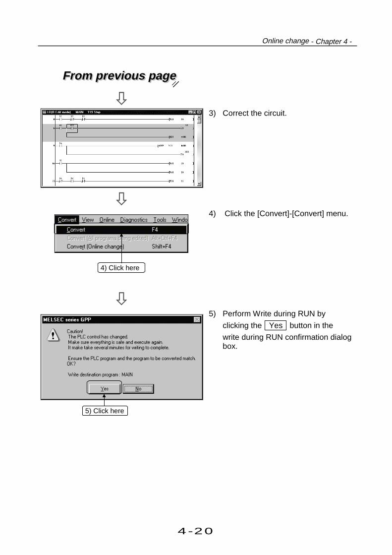
4-20
Online change - Chapter 4 -
From previous pageFrom previous page
3) Correct the circuit.
4) Click the [Convert]-[Convert] menu.
5) Perform Write during RUN by
clicking the Yes button in the
write during RUN confirmation dialogbox.
4) Click here
5) Click here

4-21
4 Online operations
4.2 Changing data during monitoring, and writing during a runThis section explains changing CPU circuit during monitoring.
1) Click the [Online]-[Monitor]-[Monitor(Write mode)] menu.
2) Select and put check marks to thecheck box on the Monitor (write)mode dialog box.
3) To make the circuit on GPPWidentical to the one in the PLC CPU,Verify with PLC is performedautomatically.
To the following pageTo the following page
2) Click here
1) Click here

4-22
Online change - Chapter 4 -
From previous pageFrom previous page
4) Correct the circuit.
5) After correcting the circuit, click the[Convert]-[Convert] menu.
6) Click the Yes button in the write
during RUN confirmation dialog box.When Write during RUN is finished,a message appears to indicate thatit is finished.
5) Click here
6) Click here

4-23
4 Online operations

Part 5
5
Useful functions
1. Offline operations1.1 Associating multiple programs ............................................ 5- 1
1.2 Changing function keys in GPPA, GPPQ, and MEDOC formats
................................................................................................. 5- 5
1.3 Setting the designated projects for quick start-up................ 5- 7
1.4 Converting files from GPPA format to GPPW format........... 5- 9
1.5 Changing project PLC type ................................................. 5-172. Operations with Windows functions2.1 Using Excel files as device comment............................. 5-19
2.2 Using Word files as device comment ............................. 5-21
2.3 Opening and editing multiple projects ............................ 5-233. Using Logic Test functions3.1 Learning operation procedures....................................... 5-27
3.2 Creating emulation of I/O and special unit..................... 5-29
3.3 Monitoring device status.................................................. 5-33
3.4 Using the timing chart for monitoring................................... 5-37
5
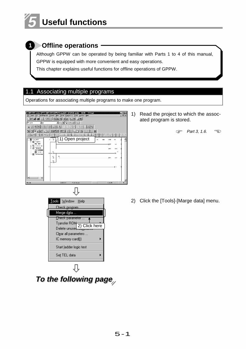
5-1
5 Useful functions
Although GPPW can be operated by being familiar with Parts 1 to 4 of this manual,
GPPW is equipped with more convenient and easy operations.
This chapter explains useful functions for offline operations of GPPW.
1 Offline operations
1.1 Associating multiple programsOperations for associating multiple programs to make one program.
1) Read the project to which the assoc-ated program is stored.
To the following pageTo the following page
2) Click the [Tools]-[Marge data] menu.
1) Open project
2) Click here
Part 3, 1.6.

5-2
Offline operations - Chapter 1 -
From previous pageFrom previous page
3) Set the source path and projectnames.
Click the Browse button. Thefollowing dialog box is displayed forsetting the source path and projectnames. Part 2, 2.4.
To the following pageTo the following page
4) Click the [Program] radio button.
5) Click the program to associate.
6) Click the Select button.
To select all programs in the project,click the Select all button.
3) Set these items
4) Click the plus mark
5) Click here
6) Click here

5-3
5 Useful functions
From previous pageFrom previous page
7) The selected program is reflected.
•To cancel, select program, and clickthe Cancel the selection button.
•To cancel all the selected programs,click the Cancel all selectionsbutton.
8) Repeat steps 3) to 7) to select thesource programs.
Association is carried out in the orderof selection from the program selectedfirst.
To the following pageTo the following page
9) Input the destination data name.
10) Click the Execute button.
The destination program can becreated only in the current project.
7) Selected programis reflected
8) Repeat steps3) to 7)
10) Click here
9) Input data name

5-4
Offline operations - Chapter 1 -
From previous pageFrom previous page
11) After confirmation, click the Yes
button.
(Only if the program exists) 12) After confirmation, click the Yes
button.
If the No button is clicked, associ-
ation is not carried out.Now, the association is completed.
11) Click here
12) Click here

5-5
5 Useful functions
1.2 Changing function keys in GPPA, GPPQ, and MEDOC formatsThis section explains changing allocation of function keys frequently used for circuit creation toGPPA, GPPQ, and MEDOC formats.
1) Click the [Tools]-[Customize keys]menu.
2) Select the key format by clicking.
3) Click the OK button.
Now, the format change is complet-ed.
1) Click here
3) Click here
2) Select format

5-6
Offline operations - Chapter 1 -
——Displaying tool bar after changing format——
The tool bars are changed as follows according to each format. The allocation of short cut
keys is also changed.
MEDOC format
GPPQ format
GPPA format
Appendix App. 1.

5-7
5 Useful functions
1.3 Setting the designated projects for quick start-upThis section explains setting the designated projects for quick start-up.
1) Read the project to start-up withGPPW.
2) Click the [Tools]-[Create start-upsetting file] menu.
3) Set the drive/path and file names.(Since extensions (*.GPS) areadded automatically, it is notnecessary to set extensions.)
4) Click the Save button to save the
file.Now the setting is completed.
1) Open project
Part 3, 1.6.
2) Click here
3) Set these projects(e.g. C:\PRO01) 4) Click here
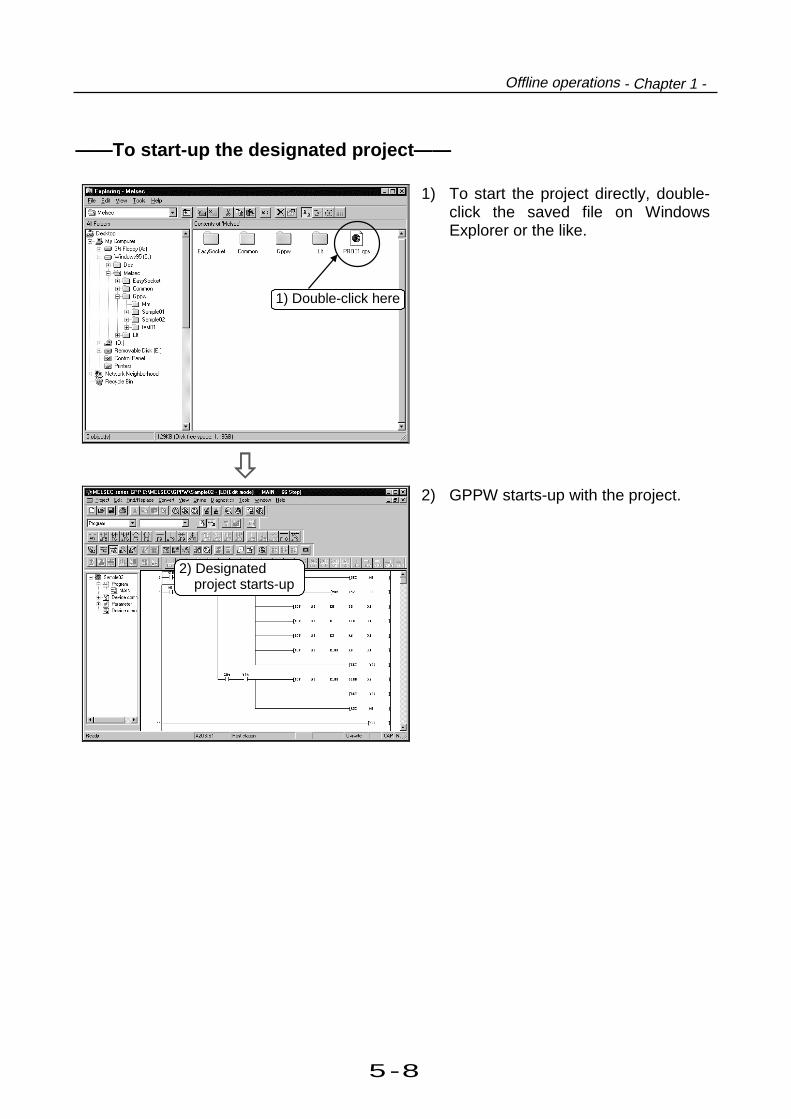
5-8
Offline operations - Chapter 1 -
——To start-up the designated project——
1) To start the project directly, double-click the saved file on WindowsExplorer or the like.
2) GPPW starts-up with the project.
2) Designatedproject starts-up
1) Double-click here

5-9
5 Useful functions
1.4 Converting files from GPPA format to GPPW formatThis section explains converting files from GPPA format to GPPW format.
1) Click the [Project]-[Import file]-[Imp-ort from GPPA format file] menu.
To the following pageTo the following page
2) Click Browse . (Use Browse to
check the drive/path, system nameand device label. If these informationare known, input them directly.)2) Click here
1) Click here

5-10
Offline operations - Chapter 1 -
From previous pageFrom previous page
3) Select drive/path, system name, anddevice label. After selection, click
OK
4) Select if all ( Select all ) or part of
GPPA data is converted to GPPW.
5) After selection, click Execute to
execute conversion.When message Completed appe-ars, conversion is completed.
3) Select here
4) Click here
5) Click here
After selection, click here

5-11
5 Useful functions
——Notes for converting GPPA comment files to GPPWcomment files——If comments in comment1 and comment2 and extension comments are attached to
the existing data, the comment data are converted to GPPW common comments.
If the comments in comment1 and comment2 and extension comments overlap,
extension comment 1 takes priority and is converted first.
a Common comment
A b Comment1
b c Comment2
de df e Extension comment 1
f
Commoncomment
Programcomment(MAIN)
Mainprogramcomment
Comment1
Programcomment(SUB1)
Sub-programcomment
Comment2
GPPW ACPU/GPPA format file
Existing GPPA file
Install
Windows 95 personal computer
GPPAGPPW
If allocation overlaps,
extension comment 1
takes priority and is
overwritten.
X4
X2
X2
X0X0
X4
Personal computer

5-12
Offline operations - Chapter 1 -
——Notes for converting GPPQ comment files to GPPW files——Program comments created by GPPQ are converted as they are.
Since GPPQ does not have a concept of common comment as GPPW does,
common comments of GPPQ can be converted to common comment of GPPW by
changing the file name to "COMMENT".
Existing GPPA file
Windows 95 personal computer
GPPAGPPW
GPPW file
GPPW QnACPU/GPPQ format
Common comment Program comment
Program comment Program comment
Program comment Program comment
File name
COMMENT
Personal computer

5-13
5 Useful functions
——Notes for writing GPPW data to ACPU/GPPA format files——Before writing data created by GPPW to ACPU, or to a floppy disk as a GPPA file,specify the memory capacity of the PC parameter (comment and extensioncomment) and the comment range for writing.
Operations for setting the device comment are explained by using the followingcircuit.
Circuit indicating device comment
1) Display the device comment editscreen.
2) Select [Edit]-[Setup commentchange].
To the following pageTo the following page
Part 3, 5.1.
2) Select and click
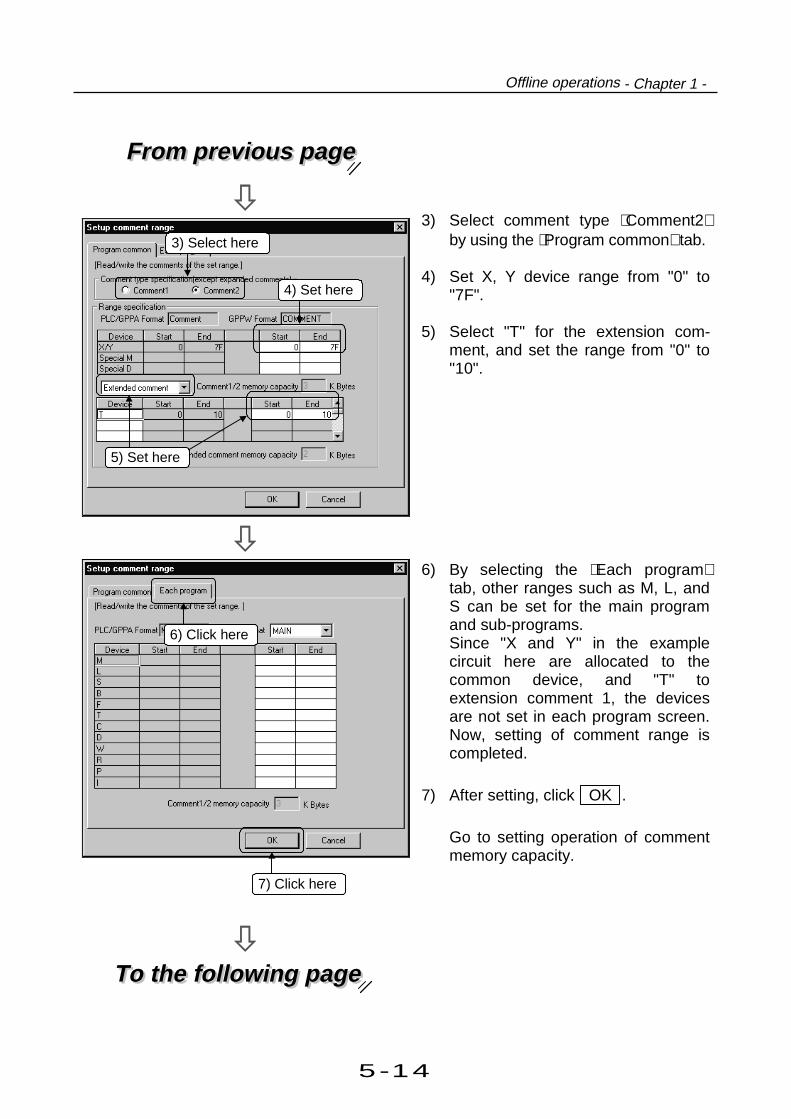
5-14
Offline operations - Chapter 1 -
From previous pageFrom previous page
3) Select comment type Comment2by using the Program common tab.
4) Set X, Y device range from "0" to"7F".
5) Select "T" for the extension com-ment, and set the range from "0" to"10".
To the following pageTo the following page
6) By selecting the Each programtab, other ranges such as M, L, andS can be set for the main programand sub-programs.Since "X and Y" in the examplecircuit here are allocated to thecommon device, and "T" toextension comment 1, the devicesare not set in each program screen.Now, setting of comment range iscompleted.
7) After setting, click OK .
Go to setting operation of commentmemory capacity.
3) Select here
4) Set here
5) Set here
7) Click here
6) Click here

5-15
5 Useful functions
From previous pageFrom previous page
8) Double click PLC parameter andopen the parameter dialog box.
9) Set the comment memory capacityto "4" and extension commentmemory capacity to "2".
After setting, click End setup .Check
Click here
8) Double click here
9) Set memory capacity
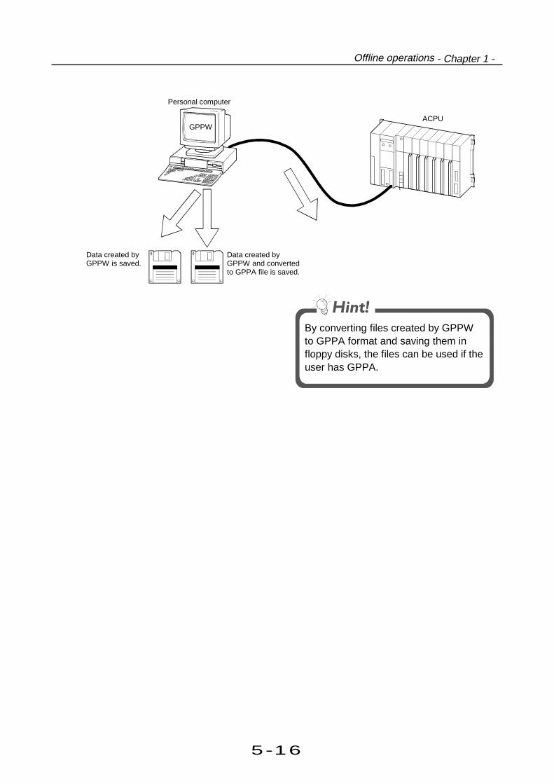
5-16
Offline operations - Chapter 1 -
Windows 95 personal computer
GPPW
Data created byGPPW and convertedto GPPA file is saved.
ACPU
Data created byGPPW is saved.
By converting files created by GPPWto GPPA format and saving them infloppy disks, the files can be used if theuser has GPPA.
Personal computer

5-17
5 Useful functions
1.5 Changing project PLC typeThis section explains changing project PLC type set in project creation.
Here, operations for changing PLC type "A2US(S1)" to "Q2AS(H)" are described.
(Changing PLC type from A series to QnA series and vice versa involves restrictions. For detail,refer to the GPPW operating manual.)
1) Click the [Project]-[Change PLC type]menu.
2) Click the PLC series list button,and select PLC series to change.Here, select "QnACPU".
To the following pageTo the following page
3) Click the PLC type list button, andselect PLC type to change.Here, select "Q2AS(H)".
4) Click the OK button.
1) Click here
4) Click here
2) Click and select"QnACPU"
3) Click and select"Q2AS(H)"

5-18
Offline operations - Chapter 1 -
From previous pageFrom previous page
5) A dialog box to confirm change is
displayed. Click the Yes button.
6) Confirm that the PLC type on thestatus bar at the bottom of thescreen is changed to "Q2AS(H)".
5) Click here
6) Click here

5-19
5 Useful functions
2 Operations with Windows functionsWindows is a well-known OS that is used worldwide.This section explains using Windows functions.
2.1 Using Excel files as device commentThis section explains using Excel files to create device comments.
The following explanation assumes that Excel and GPPW are running.
CSV or text format data can be read asthe device comment or list program ofGPPW by the optionally available dataconversion software package SW0D5C-CNVW.
(Operations in Excel)1) Click the cell containing the comm-
ent created.
2) Drag the mouse to designate therange to be used as comments. Thedesignated area is highlighted.
To the following pageTo the following page
3) Click on the tool bar of Excel.The comments in the designatedrange are copied.
Short cut
keyCCtrl
3) Click here
1) Click here
2) Drag anddesignate range

5-20
Operations with Windows functions - Chapter 2 -
From previous pageFrom previous page
(Operations on GPPW)4) Click the position to paste the
comment and move the cursor.
Set the cursor position at the top ofthe paste range.When pasted, the data is overwritten.
5) Click on the tool bar.
Short cut
keyVCtrl
6) Now the comments are created.
For comment...
Part 3, 5.1.
5) Click here
Paste range
4) Click, and movecursor
6) Paste completed
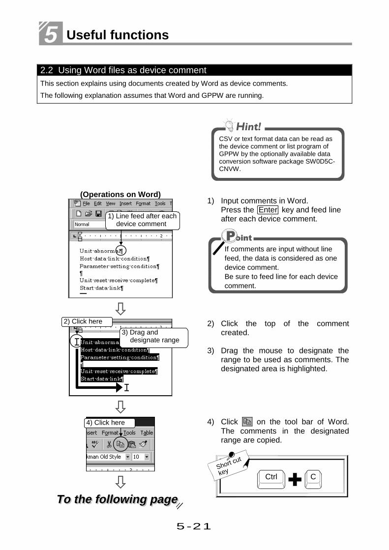
5-21
5 Useful functions
2.2 Using Word files as device commentThis section explains using documents created by Word as device comments.
The following explanation assumes that Word and GPPW are running.
CSV or text format data can be read asthe device comment or list program ofGPPW by the optionally available dataconversion software package SW0D5C-CNVW.
(Operations on Word)1) Input comments in Word.
Press the Enter key and feed lineafter each device comment.
If comments are input without linefeed, the data is considered as onedevice comment.Be sure to feed line for each devicecomment.
2) Click the top of the commentcreated.
3) Drag the mouse to designate therange to be used as comments. Thedesignated area is highlighted.
To the following pageTo the following page
4) Click on the tool bar of Word.The comments in the designatedrange are copied.
Short cut
keyCCtrl
3) Drag anddesignate range
2) Click here
4) Click here
1) Line feed after eachdevice comment

5-22
Operations with Windows functions - Chapter 2 -
From previous pageFrom previous page
(Operations on GPPW)5) Click the position to paste the
comment and move the cursor.
Set the cursor position at the top ofthe paste range.
6) Click on the tool bar.
Short cut
keyVCtrl
7) Now the comments are created.
If a line feed is input betweencomments, a comment column isblanked.
For comment...
Part 3, 5.1.
A line feed blanks acomment field
Paste range
5) Click, and movecursor
7) Paste completed
6) Click here
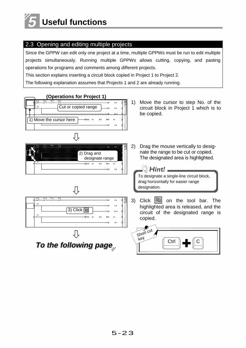
5-23
5 Useful functions
2.3 Opening and editing multiple projectsSince the GPPW can edit only one project at a time, multiple GPPWs must be run to edit multiple
projects simultaneously. Running multiple GPPWs allows cutting, copying, and pasting
operations for programs and comments among different projects.
This section explains inserting a circuit block copied in Project 1 to Project 2.
The following explanation assumes that Projects 1 and 2 are already running.
(Operations for Project 1)1) Move the cursor to step No. of the
circuit block in Project 1 which is tobe copied.
2) Drag the mouse vertically to desig-nate the range to be cut or copied.The designated area is highlighted.
To designate a single-line circuit block,drag horizontally for easier rangedesignation.
To the following pageTo the following page
3) Click on the tool bar. Thehighlighted area is released, and thecircuit of the designated range iscopied.
Short cut
keyCCtrl
2) Drag anddesignate range
3) Click
Cut or copied range
1) Move the cursor here

5-24
Operations with Windows functions - Chapter 2 -
From previous pageFrom previous page
4) Move the cursor to the screen ofProject 2, and click.
Projects can be switched by using thetask bar.
(Operations for Project 2)5) Click the circuit block (any position)
under the insert position, and movethe cursor.
6) Click on the tool bar.
Short cut
keyVCtrl
7) The copied circuit block is insertedto the Project 2 circuit.
Editing operations for circuits andcomments between projects are sameas editing within a project.
For methods of editing circuits...
For methods of editing comments...Part 3, Chapter 2.
Part 3, Chapter 6.
6) Click here
7) Insertion completed
5) Click here andmove cursor
Copied data is inserted above this circuit block
4) Click here toswitch the screen

5-25
5 Useful functions
The Logic Test function (option) is a tool that enables debugging the sequence
programs created by users without connecting PLC CPU.
This function allows debugging by using a personal computer without a debugging
equipment such as PLC CPU.
This section explains the operations of the Logic Test function.
3 Using Logic Test functions
——Outline of Logic Test function (LLT)——
Installing the Logic Test function (LLT) additionally to the personal computer installedwith GPPW enables debugging of the sequence programs in off-line status (whenGPPW is not connected to external devices such as PLC).It also allows quick development of sequence programs because program creationand debugging can be performed on the same personal computer.Debugging by the Logic Test function (LLT) is performed by writing sequenceprograms created with GPPW to the LLT. Writing is executed automatically withstart-up of the Logic Test function.
——Functions supported by Logic Test function (LLT)——
When the Logic Test function (LLT) is installed, the online menu of GPPW becomesavailable in the same way as it is connected to PLC CPU. (PLC CPU emulation)
Online menu DescriptionCircuit monitor, device monitor Monitors operating status.
Device test Overwrites the device value positively duringmonitoring.
PLC writing Writes parameter files and program files.PLC diagnostics Checks the status for error.
Skip execution Skips (does not perform) a program run in therange of the specified steps.
Step execution Operates the sequence program step by step.
Partial operation Executes the designated steps or pointer range ofthe program.
Remote operation Operates the status of the Logic Test function(LLT).
Program monitor listMonitors the run statuses and run counts ofprograms as a list and starts/stops a program inthe list.

5-26
Using Logic Test functions - Chapter 3 -
Functions performed by Logic Test function (LLT)
Function Description Refer to
DeviceMemory
Monitors the device memory states and conducts testssuch as forced ON/OFF and present value changing ofdevices.
3.3DeviceMemoryMonitor Timming
ChartMonitors and tests device states in a sequenceprogram using Timing Chart. 3.4
I/O system setting Simulates machine operations by simple setting. 3.2
Note: Other than the above functions, the Logic Test function supports the "Tool function" whichallows temporal storage of LLT device data and buffer memory data of special functionunit.
——Note for start-up of Logic Test function (LLT)——
If QnACPU is selected for PLC series, set the Program tab of the PLC parameter forGPPW as follows. (For A series, no setting is required.)
——Processing time of sequence program in Logic Test function——
The actual processing time of the sequence program depends on the performance ofthe personal computer and the operation environment of other applications.
Be sure to set a program nameeven if there is only one programClick MAIN, and
click Insert
Select program

5-27
5 Useful functions
3.1 Learning operation procedures
This section explains debugging with the Logic Test function (LLT).
The following explanation assumes that GPPW and the Logic Test function are installed.
1) Confirm that the project is open,and click the [Tools]-[Start ladderlogic test] menu.
To the following pageTo the following page
2) The Logic Test function starts-up.
•When the Logic Test function (LLT)starts-up, the parameter andprogram are written simultaneously(equivalent to PLC write).
•If QnACPU is used, program settingof the PLC parameter is required.
1) Click here
2) Logic test function(LLT) starts-up
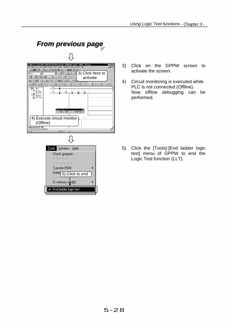
5-28
Using Logic Test functions - Chapter 3 -
From previous pageFrom previous page
3) Click on the GPPW screen toactivate the screen.
4) Circuit monitoring is executed whilePLC is not connected (Offline).Now offline debugging can beperformed.
5) Click the [Tools]-[End ladder logictest] menu of GPPW to end theLogic Test function (LLT).
3) Click here toactivate
4) Execute circuit monitor (Offline)
5) Click to end

5-29
5 Useful functions
3.2 Creating emulation of I/O and special unitThis section explains creating emulation of I/O and special unit such as "turning X0 ON when Y5and Y7 are ON."
After 5 secondsY2 and Y3 are ON X5 is ON
Emulation to be created Operations for creating the emulation as
shown on the left are explained.
(I/O system is set in setting No.1.)
1) Click the [Start]-[I/O system settings]menu of the Logic Test function(LLT).
2) Double click the upper text box of thesetting No.1 Condition.
To the following pageTo the following page
3) Set the device name (Y), devicenumber (2), and ON/OFFdesignation (ON).
4) Click the OK button.
2) Double click here
1) Click here
4) Click here
3) Set these items

5-30
Using Logic Test functions - Chapter 3 -
From previous pageFrom previous page
5) The setting result is displayed.
Setting can also be done by inputting"Y2=ON".
6) Repeat steps 2) to 5) for setting thelower text box.
7) Click the AND radio button.
8) Input "500" (5 sec) to theTimer textbox.
To the following pageTo the following page
9) Double click the Input(SimulationDevice text box.
7) Click here
8) Input here
5) Setting result is displayed
9) Double click here
6) Repeat steps2) to 5)

5-31
5 Useful functions
From previous pageFrom previous page
10) Set the device name (X) and thedevice number (5).
11) Click the OK button.
12) The setting result is displayed.
Setting can also be done by inputting"X5".
13) Click the ON radio button.
14) Click the check to put a check markto validate the setting.
To the following pageTo the following page
15) Click the OK button at the lower-
left of the screen.
13) Click here
12) Setting resultis displayed
14) Check
15) Click here
11) Click here
10) Set these items

5-32
Using Logic Test functions - Chapter 3 -
From previous pageFrom previous page
16) Input the file name to save the creat-ed emulation.(Input "Sample.txt" here.)
17) Click the Save button.
18) Click the Yes button.
18) Click here
16) Input file name
17) Click here
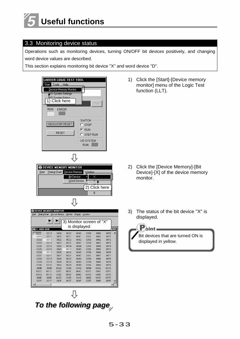
5-33
5 Useful functions
3.3 Monitoring device statusOperations such as monitoring devices, turning ON/OFF bit devices positively, and changing
word device values are described.
This section explains monitoring bit device "X" and word device "D".
1) Click the [Start]-[Device memorymonitor] menu of the Logic Testfunction (LLT).
2) Click the [Device Memory]-[BitDevice]-[X] of the device memorymonitor.
To the following pageTo the following page
3) The status of the bit device "X" isdisplayed.
Bit devices that are turned ON isdisplayed in yellow.
1) Click here
2) Click here
3) Monitor screen of "X"is displayed

5-34
Using Logic Test functions - Chapter 3 -
From previous pageFrom previous page
4) Click [Device Memory]-[WordDevice]-[D] of the device memorymonitor.
5) Status of word device "D" isdisplayed.
6) Confirm that monitoring is ON.
If the monitoring is OFF, click the F3:START/STOP button to start
monitoring.
4) Click here
5) Monitor screen of "D"is displayed
6) Confirm here

5-35
5 Useful functions
——Turning ON/OFF bit device positively ——
1) Double click the device No. to beturned ON/OFF positively.
2) The designated bit device No. isturned ON and displayed in yellow.
1) Double click here
2) Bit device is turned ON
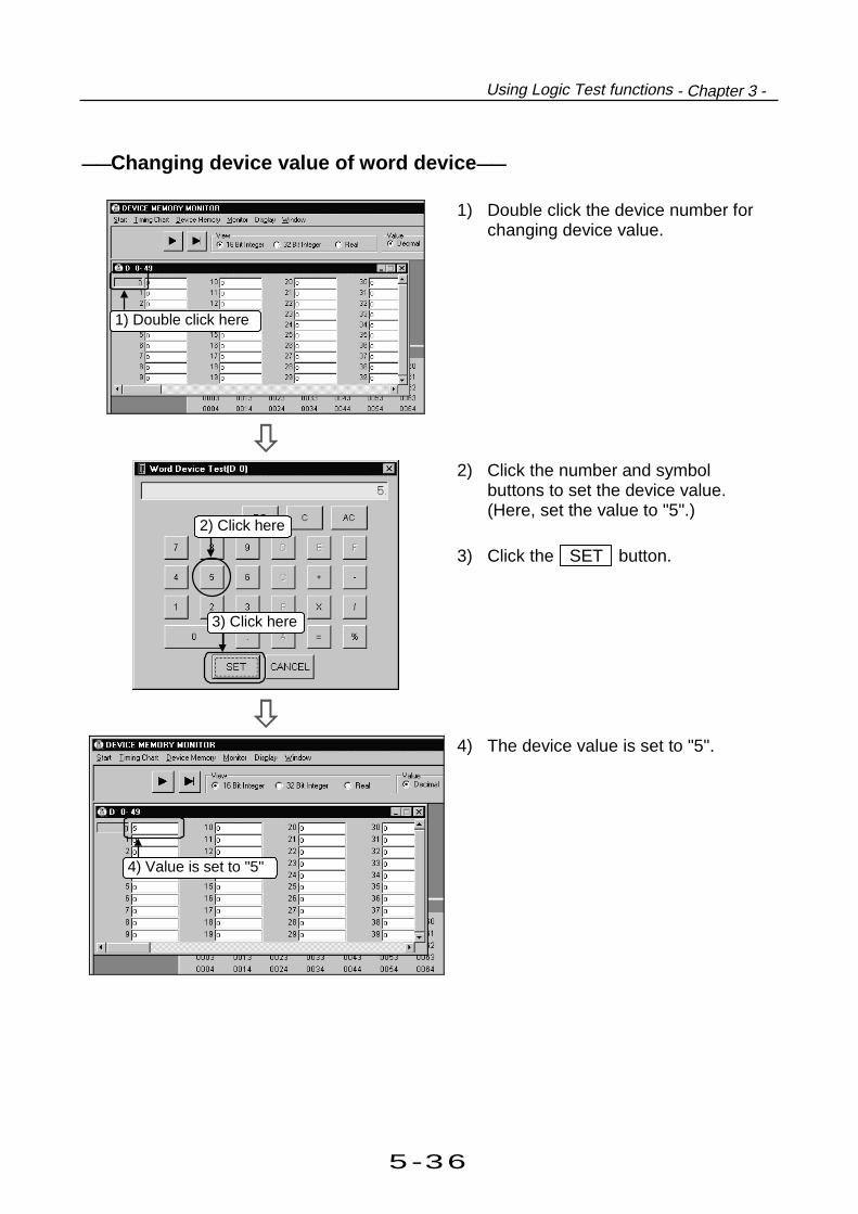
5-36
Using Logic Test functions - Chapter 3 -
——Changing device value of word device ——
1) Double click the device number forchanging device value.
2) Click the number and symbolbuttons to set the device value.(Here, set the value to "5".)
3) Click the SET button.
4) The device value is set to "5".
1) Double click here
2) Click here
3) Click here
4) Value is set to "5"

5-37
5 Useful functions
3.4 Using the timing chart for monitoringThis section explains operations to indicate device changes per elapsed time during monitoring.
Here, the following circuit is used as an example to perform operations to monitor the change
timing of the value stored in "D100" when "X1" turns ON/OFF.
Circuit example for timing chart
1) Click the [Start]-[Device MemoryMonitor] menu of the logic testfunction (LLT).
To the following pageTo the following page
2) Click the [Timing Chart]-[Run] menuof Device Memory Monitor.
1) Click here
2) Click here

5-38
Using Logic Test functions - Chapter 3 -
From previous pageFrom previous page
3) As the Timing Chart screen appears,
click the Monitor Stop button.
If [Device Entry] is "Auto", thedevices being displayed in the circuitare automatically entered.
If you want to display the specifieddevice, enter it "manually" from the[Device]-[Enter Device] menu.
To the following pageTo the following page
4) Status changes to Monitoring and
the states per scan time aredisplayed.
The indications of bit devices differfrom those of word devices.Timing Chart provides the followingindications.
Bit device
Turns to yellowat ON
ON OFF
Word device
Presentvalue
Valueupdate
4) Monitoring starts
3) Click here

5-39
5 Useful functions
From previous pageFrom previous page
5) Double-clicking "X1" forces it to turnON/OFF.Turning "X1" ON three times turns"C1" ON and stores 1 into "D100".
To change the present value of aword device, enter a new value intothe text box on the left side of thedevice name.
To the following pageTo the following page
6) To change the device display order,drag and drop the device to theexchange position.
The device display order can also bechanged on the Device List screen ofthe [Device]-[List Device] menu.To change the order on the DeviceList screen, choose the device andclick / .
Click to move up/down
Choose device
5) Double click here
6) Drag and drop

5-40
Using Logic Test functions - Chapter 3 -
From previous pageFrom previous page
7) As [Device Entry] switches to
"Manual", click the OK button.
8) [Device Entry] switches to "Manual"and the device display orderchanges.
9) Click the Monitoring button to
stop Timing Chart.With the scroll bar at the bottom ofthe screen, you can confirm up to1000 device states.
In "Range of Chart Display", you canchange the display unit between 1 and 20.
7) Click here
8) Positions are exchanged
9) Click here
Scroll to confirm

5-41
5 Useful functions

Appendix
App
Appendix
AppendixApp. 1 Short cut key list ..........................................................App- 1
App. 2 Circuit creation list .......................................................App- 7
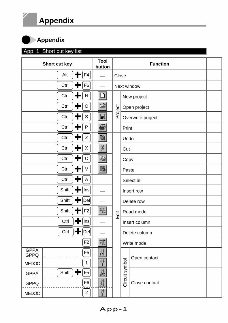
App-1
Appendix
Appendix
App. 1 Short cut key list
Short cut keyTool
buttonFunction
Alt F4 — Close
Ctrl F6 — Next window
Ctrl N New project
Ctrl O Open project
Ctrl S Overwrite project
Ctrl P
Pro
ject
Ctrl Z Undo
Ctrl X Cut
Ctrl C Copy
Ctrl V Paste
Ctrl A — Select all
Shift Ins — Insert row
Shift Del — Delete row
Shift F2 Read mode
Ctrl Ins — Insert column
Ctrl Del — Delete column
F2 Write mode
GPPAGPPQ F5
MEDOC 1Open contact
GPPA Shift F5
GPPQ F6
MEDOC 2
Edi
t
Circ
uit s
ymbo
l
Close contact

App-2
Short cut key list - App.1 -
Description
Close the active window.
Open the next window.
Create a new project.
Open an existing project file.
Overwrite the project file.
Print the project.
Undo the previous operation.
Move the selected data to the clipboard.
Copy the selected data to the clipboard.
Paste the data on the clipboard to the cursor position.
Select all items.
Insert a row to the cursor position.
Delete a row at the cursor position.
Set to read mode.
Insert a column to the cursor position.
Delete a column at the cursor position.
Set to write mode.
Write an open contact to the cursor position.
Write a close contact to the cursor position.

App-3
Appendix
Short cut key Toolbutton Function
GPPA F6
GPPQ Shift F5
MEDOC 3
Open branch
GPPAGPPQ Shift F6
MEDOC 4Close branch
GPPAGPPQ F7
MEDOC 7Coil
GPPAGPPQ F8
MEDOC 8Application instruction
GPPAGPPQ F9
MEDOC 6Horizontal line
GPPA F10
GPPQ Shift F9
MEDOC 5
Vertical line
GPPAGPPQ Ctrl F9
MEDOC 9Delete horizontal line
GPPAGPPQ Ctrl F10
MEDOC 0Delete vertical line
Shift F7 Rising pulse
Shift F8 Falling pulse
Alt F7 Rising pulse open branch
Alt F8 Falling pulse close branch
Alt F5 Convert operation results to risingpulse
Ctrl Alt F5
Edi
t
Circ
uit s
ymbo
l
Convert operation results to fallingpulse
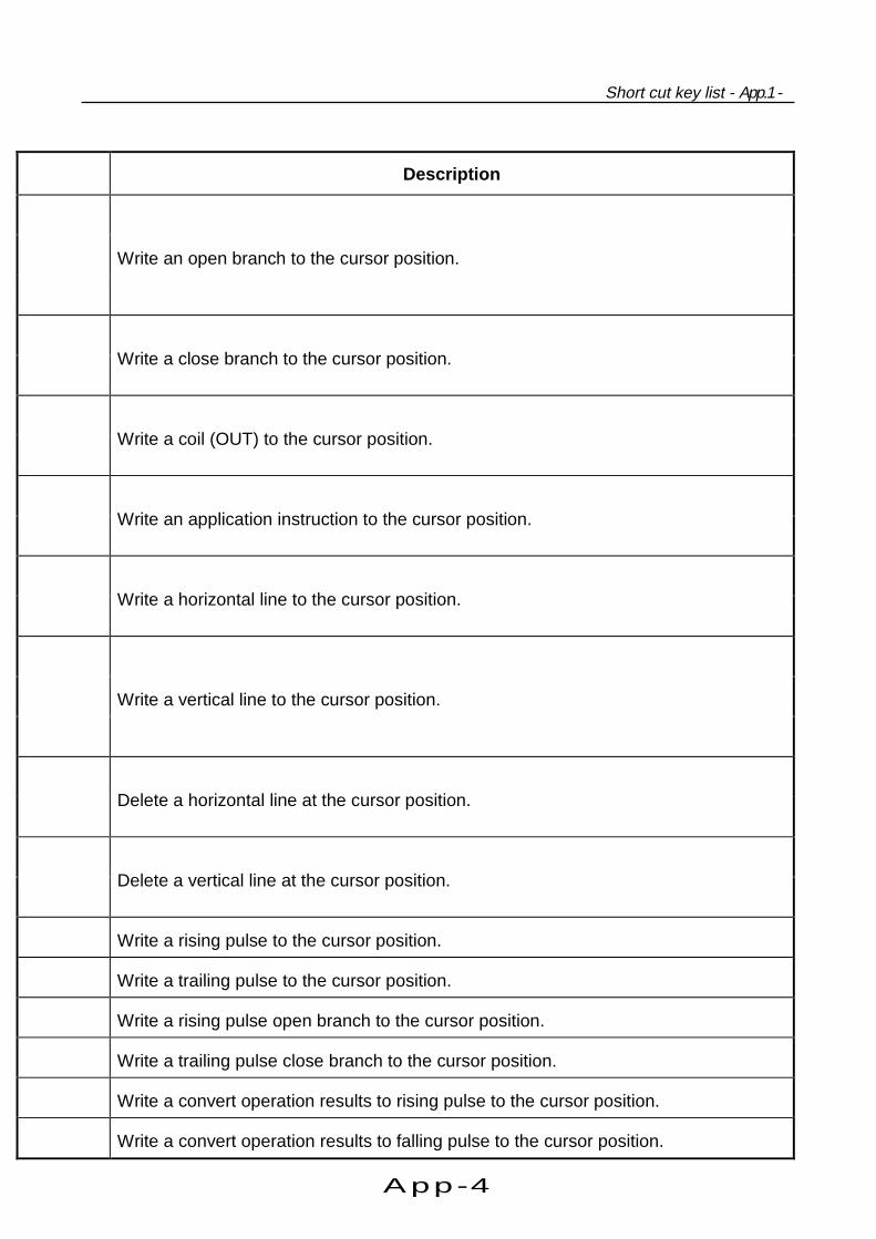
App-4
Short cut key list - App.1 -
Description
Write an open branch to the cursor position.
Write a close branch to the cursor position.
Write a coil (OUT) to the cursor position.
Write an application instruction to the cursor position.
Write a horizontal line to the cursor position.
Write a vertical line to the cursor position.
Delete a horizontal line at the cursor position.
Delete a vertical line at the cursor position.
Write a rising pulse to the cursor position.
Write a trailing pulse to the cursor position.
Write a rising pulse open branch to the cursor position.
Write a trailing pulse close branch to the cursor position.
Write a convert operation results to rising pulse to the cursor position.
Write a convert operation results to falling pulse to the cursor position.

App-5
Appendix
Short cut keyTool
button Function
Ctrl Alt F10 Invert operation results
GPPA Alt F10
GPPQMEDOC F10
Write horizontal rule
Alt F9
Edi
t
Circ
uit s
ymbo
l
Delete horizontal rule
F4 Convert
Ctrl Alt F4 Convert (all program being edited)
Shift F4 —C
onve
rtConvert (write during run)
Ctrl F5 — Display comment
Ctrl F7 — Display statement
Ctrl F8 — Display note
Ctrl Alt F6 — Display system name
Alt 0
Dis
play
Project data list
F3 Monitor
Ctrl F3 — Monitor (all windows)
Shift F3 Monitor (write mode)
F3 Monitor start
Alt F3 Monitor stop
Ctrl Alt F3 —
Mon
itor
Monitor stop (all windows)
Alt 1 Device test
Alt 2 Skip
Alt 3 Partial operation
Alt 4
Deb
ug
Execute step
Alt 6 — Remove operation
Alt F1
Onl
ine
Switch circuit/list

App-6
Short cut key list - App.1 -
Description
Write the reversed operation result to the cursor position.
Write a ruled line.
Delete a ruled line.
Convert program.
Convert all programs being edited in batch.
Convert program and write to the running CPU.
Switch ON/OFF the comment display.
Switch ON/OFF the statement display.
Switch ON/OFF the note display.
Switch ON/OFF the system name display.
Switch ON/OFF the project data list display.
Execute circuit monitoring.
Execute circuit monitoring for all open programs.
Set to write mode during circuit monitoring.
Start (restart) circuit monitoring.
Stop circuit monitoring.
Stop circuit monitoring for all open programs.
Turn ON/OFF devices positively or change the present values.
Skip the sequence program in the designated range.
Execute part of sequence program.
Run PLC CPU step by step.
Carry out remote operation.
Switch between circuit screen and list screen.

App-7
Appendix
App. 2 Circuit creation list
Example List expression Tool button Function
X1"LD X1" +"X1" F5 +"X1"
X1"LDI X1" +"X1" F6 +"X1"
X1"OR X1" +"X1" Shift F5 +"X1"
X1"ORI X1" +"X1" Shift F6 +"X1"
Y1"OUT Y1" +"Y1" F7 +"Y1"
MOV K1 DO"MOV K1 D0" +"M O V K1 D O" F8 +"MOV K1 DO"
— +Number of lines F9 +Number of lines
— +Number of lines Shift F9 + N um ber o f lines
— +Number of lines Ctrl F9 +Number of lines
— +Number of lines Ctrl F10 +Number of lines
X1"ANDP X1" +"X1" Shift F7 +"X1"
X1"ANDF X1" +"X1" Shift F8 +"X1"
X1"ORP X1" +"X1" Alt F7 +"X1"
X1"ORF X1" +"X1" Alt F8 +"X1"
"MEP" Alt F5
"MEF" Ctrl Alt F5
"INV" Ctrl Alt F10
— +Drag F10 +Drag
— +Drag Alt F9 +Drag

App-8
Circuit creation list - App.2 -
*1 After inputting instructions, press the Enter key or click the OK
button.
*2 This table shows operations for keys customized for GPPQ.
Menu
[Edit]-[Ladder symbol]-[Open conact]+"X1"
[Edit]-[Ladder symbol]-[Close contact]+"X1"
[Edit]-[Ladder symbol]-[Open branch]+"X1"
[Edit]-[Ladder symbol]-[Close branch]+"X1"
[Edit]-[Ladder symbol]-[Coil]+"Y1"
[Edit]-[Ladder symbol]-[Application instruction]+"MOV K1 DO"
[Edit]-[Ladder symbol]-[Horizontal line]+Number of lines
[Edit]-[Ladder symbol]-[Vertical line]+Number of lines
[Edit]-[Ladder symbol]-[Delete horizontal line]+Number of lines
[Edit]-[Ladder symbol]-[Delete vertical line]+Number of lines
[Edit]-[Ladder symbol]-[Rising pulse]+"X1"
[Edit]-[Ladder symbol]-[Falling pulse]+"X1"
[Edit]-[Ladder symbol]-[Rising pulse open branch]+"X1"
[Edit]-[Ladder symbol]-[Falling pulse close branch]+"X1"
[Edit]-[Ladder symbol]-[Convert operation results to rising pulse]
[Edit]-[Ladder symbol]-[Convert operation results to falling pulse]
[Edit]-[Ladder symbol]-[Invert operation results]+"X1"
[Edit]-[Draw line]+Drag
[Edit]-[Delete line]+Drag

Index
<A>Associating programs................................5- 1
<C>Circuit
Scaling of circuit .................................. 2-19
Creating a circuit with
list expressions .....................................3- 3
Creating a circuit with tool
buttons..................................................3- 7
Creating rules (circuit).......................... 3-27
Deleting rules (circuit) .......................... 3-27
Cutting a circuit block........................... 3-21
Copying a circuit block......................... 3-21
Inserting circuits by line ....................... 3-25
Deleting circuits by line ........................ 3-25
Circuit creation list .............................App-7
Changing function key allocation...............5- 5
Cutting
Cutting a circuit block........................... 3-21
Cutting a comment............................... 3-53
Cutting multiple comments................... 3-55
Creating a ruled line
Creating a ruled line............................. 3-27
Deleting a ruled line ............................. 3-27
Copying
Copying a circuit block......................... 3-21
Copying a comment............................. 3-57
Creating
Creating a circuit (list expressions) .......3- 3
Creating a circuit (tool buttons) .............3- 7
Creating a ruled line (circuit) ................ 3-27
Creating a comment ............................ 3-43
Creating a statement............................3-47
Creating a note ....................................3-49
Creating a circuit with tool buttons .............3- 7
Converting................................................3-11
Creating a comment with Excel ................5-19
Creating a comment with Word ................5-21
<D>Deleting
Deleting circuits by line ........................3-25
Deleting a ruled line (circuit).................3-28
Deleting a comment .............................3-53
Device comment
What is a comment? ............................3-39
Creating a comment.............................3-43
Creating a comment with Excel............5-19
Creating a comment with Word ............5-21
Editing a comment ...............................3-51
Deleting and cutting a comment...........3-53
Deleting and cutting multiple
comments ............................................3-55
Copying a comment .............................3-57
Display format of edit screen ....................2-20
<E>Ending
Ending GPPW......................................2-13
Edit screen ................................................2- 8

Index
<G>GPPW
What GPPW can do..............................1- 1
Installation ............................................1- 7
System configuration ........................... 1-19
Operation flow ..................................... 1-21
Screen configuration.............................2- 7
Starting GPPW .................................... 2-11
Ending a GPPW session...................... 2-13
Editing multiple GPPWs
simultaneously..................................... 5-23
<I>Installation.................................................1- 7
Installation of GPPW.............................1- 7
Installation of license key FD ............... 1-13
<L>Logic Test function
Procedures for operation ..................... 5-27
Creating emulation............................... 5-29
Monitoring device status ...................... 5-33
Timing chart......................................... 5-37
<M>Mouse operations to enlarge window ........2- 3
Mouse operation
Basic operation.....................................2- 1
Enlarging window .................................2- 3
Scroll bar operation...............................2- 3
Menu operation.....................................2- 4
Project list operation .............................2- 4
Dialog box operation.............................2- 5
Menu bar...................................................2- 8
<N>Note
What is a note?....................................3-40
Creating a note ....................................3-47
Searching a note..................................3-59
Editing a note.......................................3-61
<O>Online change
Writing data during run of
the PLC CPU .......................................4-15
Changing data during monitoring .........4-17
Online operations
Connection Setup ................................4- 1
Writing and reading...............................4- 7
Monitoring circuit status ........................4- 9
Monitoring designated device ..............4-13
Turning ON/OFF contact positively ......4-15
Executing program step by step...........4-17
Operating the scroll bar with mouse ..........2- 3
Operation flow-chart .................................1-21
Operating dialog box with mouse...............2- 5
<P>Printing
Printing circuit ......................................3-63
Printing contacts or coils in use............3-65
Printing device in use...........................3-67
Printing listed device
comment in use ...................................3-69

Index
Project
What is a project?.................................2- 9
Designation of a project ....................... 2-15
Setting of a project............................... 2-17
Creating a project .................................3- 1
Saving a project................................... 3-15
Reading a project ................................ 3-17
Opening the designated project
at start-up .............................................5- 7
Editing multiple projects
simultaneously..................................... 5-23
Mouse operation of project list ..............2- 4
Project list .............................................2- 8
<R>Replacing
Replacing with designated device........ 3-33
Replacing A contact with B contact
and vice versa ..................................... 3-37
Reading (project)...................................... 3-17
Reading a GPPA file on GPPW.................5- 9
<S>Screen configuration
Title bar ................................................2- 8
Menu bar ..............................................2- 8
Project data list .....................................2- 8
Edit screen ...........................................2- 8
Starting
Starting GPPW .................................... 2-11
Opening the designated
project during start-up...........................5- 7
Searching a circuit
Searching with designated device........3-29
Searching with step No. .......................3-31
Searching with statement.....................3-59
Searching with note .............................3-59
System configuration ................................1-19
Short cut key list .................................... App-1
Status bar..................................................2- 8
Statement
What is statement? ..............................3-40
Creating a statement............................3-47
Searching a statement .........................3-59
Editing a statement ..............................3-61
<T>To start-up GPPW with
the designated project ...............................5- 7
Title bar .....................................................2- 8
<U>Uninstalling method..................................1-15
<W>What GPPW can do ..................................1- 1

Recommended