Schlumberger Carbon ServicesPracticality of Verification
Schlumberger Private
CCSA Seminar Melbourne26th February 2007Geoff Ingram, Regional Manager - Australasia
2
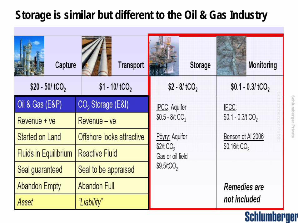
Storage is similar but different to the Oil & Gas Industry
3
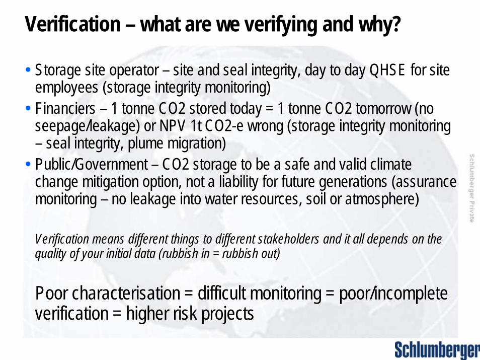
Verification – what are we verifying and why?
• Storage site operator – site and seal integrity, day to day QHSE for site employees (storage integrity monitoring)
• Financiers – 1 tonne CO2 stored today = 1 tonne CO2 tomorrow (no seepage/leakage) or NPV 1t CO2-e wrong (storage integrity monitoring – seal integrity, plume migration)
• Public/Government – CO2 storage to be a safe and valid climate change mitigation option, not a liability for future generations (assurance monitoring – no leakage into water resources, soil or atmosphere)
Verification means different things to different stakeholders and it all depends on the quality of your initial data (rubbish in = rubbish out)
Poor characterisation = difficult monitoring = poor/incomplete verification = higher risk projects
4
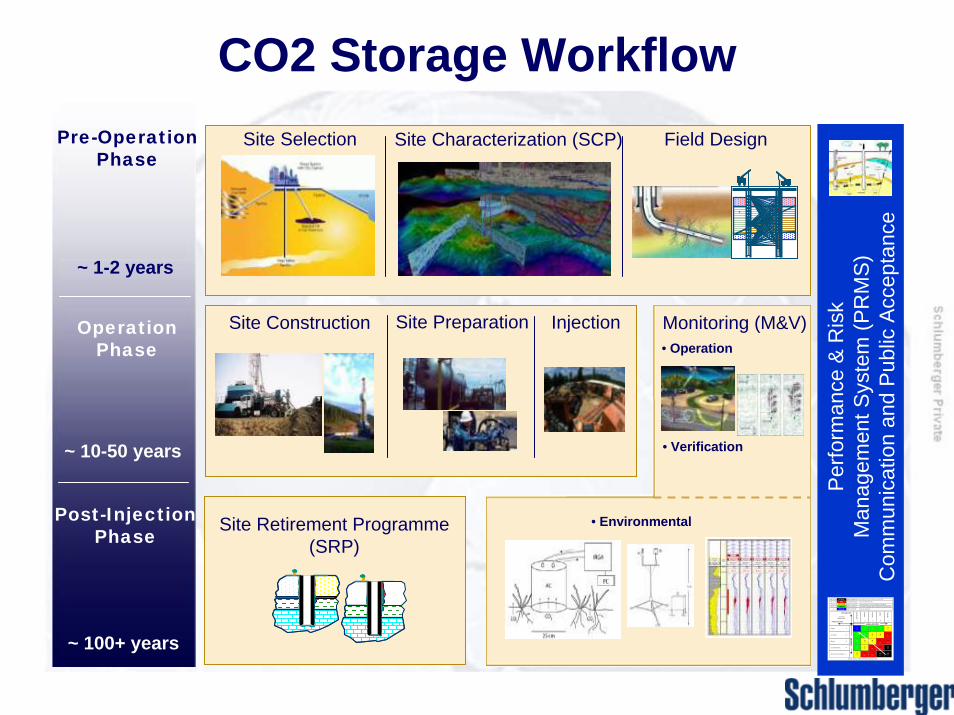
CO2 Storage WorkflowSite Selection Site Characterization (SCP) Field Design
Site PreparationSite Construction Injection
Per
form
ance
& R
isk
M
anag
emen
t Sys
tem
(PR
MS
)C
omm
unic
atio
n an
d P
ublic
Acc
epta
nce
SEVERITY
-11L
-21S
-41C
-31M
-51M C
-22L
-41S
-62M
-82C
-102M C
-33L
-63S
-93M
-123C
-153M C
-44L
-55L
-84 S
-124M
-164C
-204M C
-105S
-155M
-205C
-255M C
-1Light
-2
-3
-4
-5
Serious
Major
Catas troph ic
Multi-C atas troph ic
321
Possible
Unlikely
Improbable
5
Probable
4
Likely
LIKE LIHO O D
W hite arrow ind ica tes decreas ing risk
PR EV EN TION
M ITIG ATIO N
Contro lM easures
RE D
B LU E
YE LLO WG R EE N
IN TO LE RA B LE : D o n ot tak e th is risk
U N DE SIR AB LE : D em on stra te A LA RP be fore pro cee din g
A C CE PT A BLE : P roc eed ca refu lly, w ith co ntin uou s im p rove me nt
N E GLIG IBL E: S afe to proc eed
-16 to -1 0
-9 to -5
-4 to -2
-1
BLACK N O N-O PE RA B LE : E vacua te the zone and or a rea /coun try-25 to -2 0
Pre-OperationPhase
~ 10-50 years
~ 1-2 years
OperationPhase
~ 100+ years
Post-Injection Phase Site Retirement Programme
(SRP)
Monitoring (M&V)• Operation
• Verification
• Environmental
5
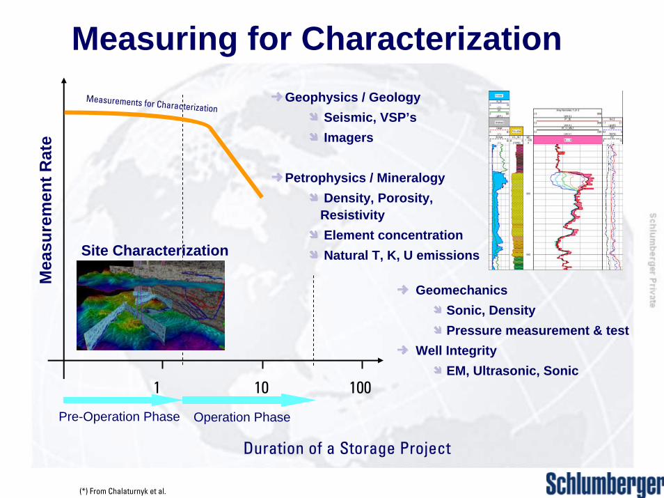
Measuring for Characterization
Duration of a Storage Project
(*) From Chalaturnyk et al.
Mea
sure
men
t Rat
e
1 10 100
Operation PhasePre-Operation Phase
Site Characterization
Measurements for CharacterizationGeophysics / Geology
Seismic, VSP’sImagers
Petrophysics / MineralogyDensity, Porosity,
Resistivity Element concentrationNatural T, K, U emissions
GeomechanicsSonic, DensityPressure measurement & test
Well IntegrityEM, Ultrasonic, Sonic
6
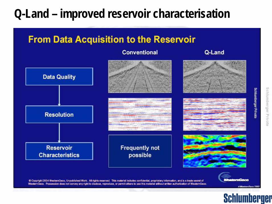
Q-Land – improved reservoir characterisation
7
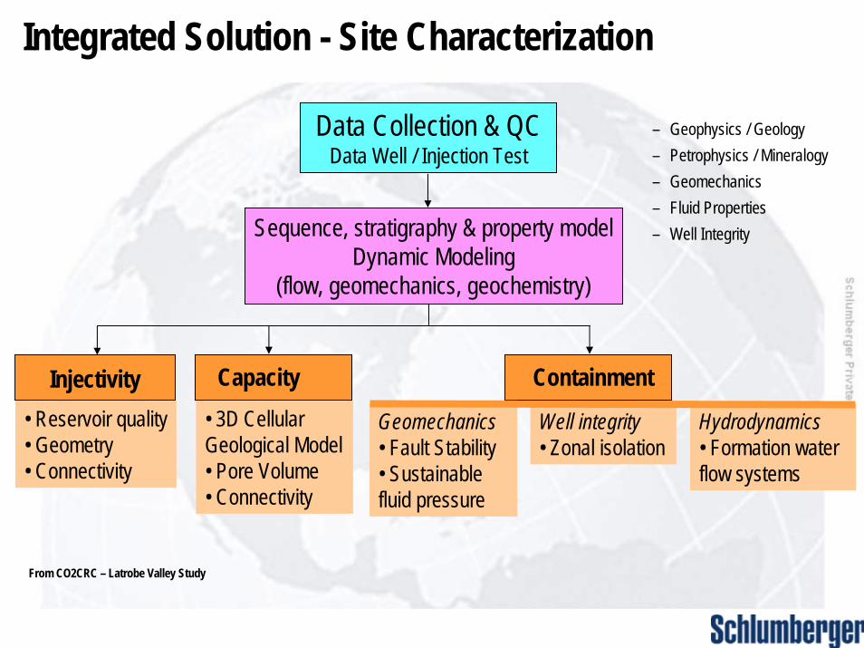
Integrated Solution - Site Characterization
Data Collection & QCData Well / Injection Test
Sequence, stratigraphy & property modelDynamic Modeling
(flow, geomechanics, geochemistry)
Capacity Containment
Geomechanics• Fault Stability• Sustainable fluid pressure
Well integrity• Zonal isolation
Hydrodynamics• Formation water flow systems
Injectivity• Reservoir quality• Geometry• Connectivity
• 3D Cellular Geological Model• Pore Volume• Connectivity
– Geophysics / Geology– Petrophysics / Mineralogy– Geomechanics– Fluid Properties– Well Integrity
From CO2CRC – Latrobe Valley Study
8
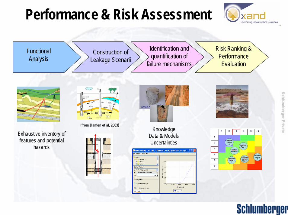
Performance & Risk Assessment
Risk Ranking &PerformanceEvaluation
Construction of Leakage Scenarii
(from Damen et al, 2003)
Functional Analysis
Exhaustive inventory of features and potential
hazards
Identification and quantification of
failure mechanisms
KnowledgeData & ModelsUncertainties
9
10
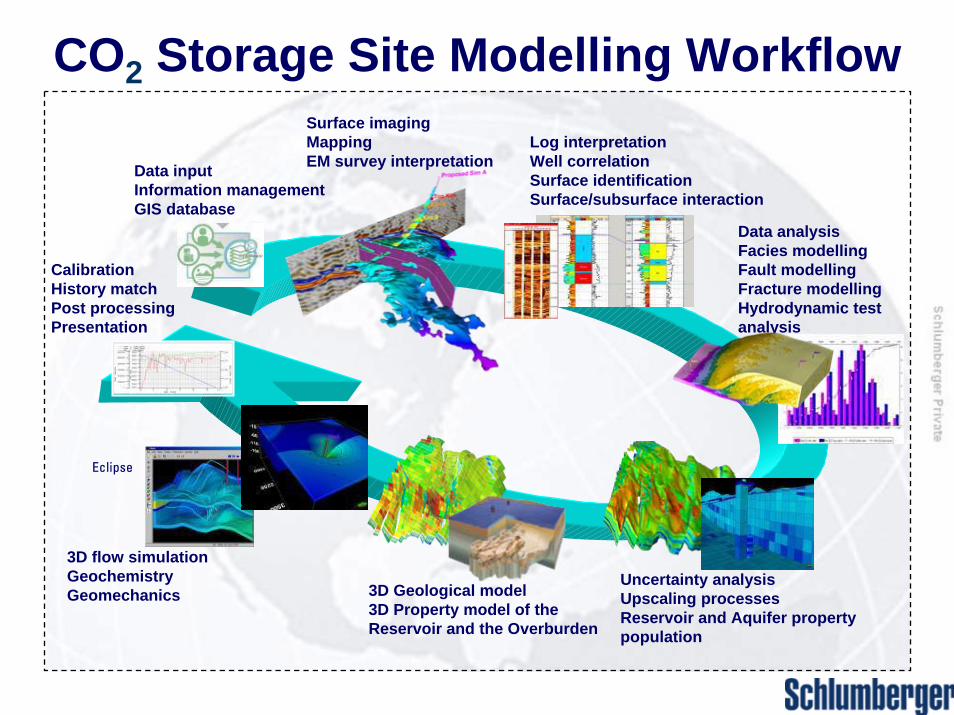
CO2 Storage Site Modelling WorkflowSurface imaging MappingEM survey interpretationData input
Information managementGIS database
Log interpretationWell correlationSurface identificationSurface/subsurface interaction
Uncertainty analysisUpscaling processesReservoir and Aquifer property population
CalibrationHistory matchPost processingPresentation
Data analysisFacies modellingFault modellingFracture modellingHydrodynamic test analysis
3D flow simulationGeochemistryGeomechanics
Eclipse
3D Geological model3D Property model of the Reservoir and the Overburden
11
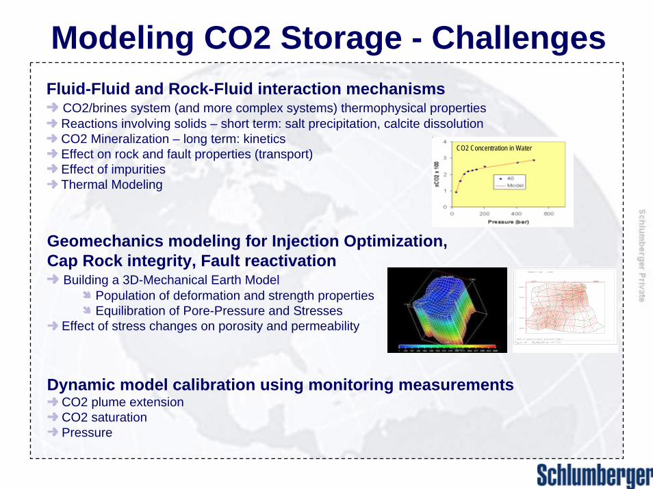
Modeling CO2 Storage - ChallengesFluid-Fluid and Rock-Fluid interaction mechanisms
CO2/brines system (and more complex systems) thermophysical propertiesReactions involving solids – short term: salt precipitation, calcite dissolutionCO2 Mineralization – long term: kinetics Effect on rock and fault properties (transport)Effect of impuritiesThermal Modeling
Geomechanics modeling for Injection Optimization, Cap Rock integrity, Fault reactivation
Building a 3D-Mechanical Earth ModelPopulation of deformation and strength propertiesEquilibration of Pore-Pressure and Stresses
Effect of stress changes on porosity and permeability
Dynamic model calibration using monitoring measurementsCO2 plume extensionCO2 saturationPressure
CO2 Concentration in Water
12
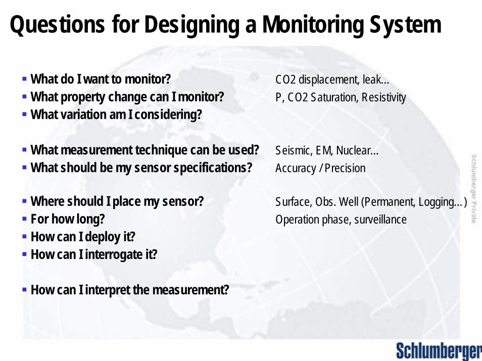
Questions for Designing a Monitoring System
What do I want to monitor? CO2 displacement, leak…What property change can I monitor? P, CO2 Saturation, ResistivityWhat variation am I considering?
What measurement technique can be used? Seismic, EM, Nuclear…What should be my sensor specifications? Accuracy / Precision
Where should I place my sensor? Surface, Obs. Well (Permanent, Logging…)For how long? Operation phase, surveillanceHow can I deploy it?How can I interrogate it?
How can I interpret the measurement?
13
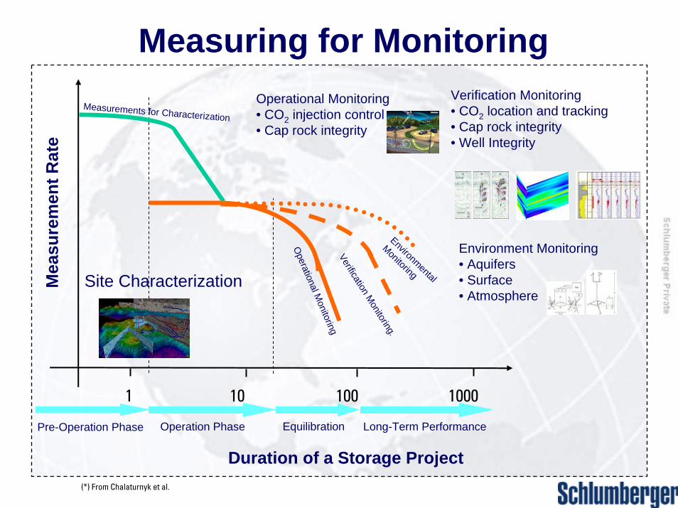
Measuring for Monitoring
Verification Monitoring.
Verification Monitoring• CO2 location and tracking• Cap rock integrity• Well Integrity
Duration of a Storage Project
1 10 100 1000
Mea
sure
men
t Rat
e
Operation Phase Equilibration Long-Term PerformancePre-Operation Phase
Site Characterization
Measurements for Characterization
Operational M
onitoring
Operational Monitoring• CO2 injection control• Cap rock integrity
Environmental
Monitoring
Environment Monitoring• Aquifers• Surface• Atmosphere
(*) From Chalaturnyk et al.
14
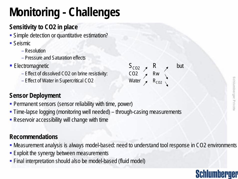
Monitoring - Challenges Sensitivity to CO2 in place
Simple detection or quantitative estimation?Seismic
– Resolution– Pressure and Saturation effects
Electromagnetic SCO2 R but– Effect of dissolved CO2 on brine resistivity: CO2 Rw– Effect of Water in Supercritical CO2 Water RCO2
Sensor DeploymentPermanent sensors (sensor reliability with time, power)Time-lapse logging (monitoring well needed) – through-casing measurementsReservoir accessibility will change with time
RecommendationsMeasurement analysis is always model-based: need to understand tool response in CO2 environmentsExploit the synergy between measurementsFinal interpretation should also be model-based (fluid model)
15
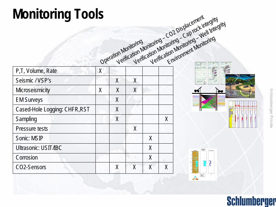
Monitoring Tools
P,T, Volume, Rate X Seismic / VSP’s X XMicroseismicity X X X EM Surveys XCased-Hole Logging: CHFR,RST XSampling X XPressure tests XSonic: MSIP XUltrasonic: USIT/IBC XCorrosion XCO2-Sensors X X X X
Operation Monitoring
Verification Monitoring – CO2 Displacement
Verification Monitoring – Cap rock integrity
Verification Monitoring – Well Integrity
Environment Monitoring
16
17
Conclusion• Tools exist for comprehensive monitoring of all stages of a CO2 storage project• Baseline data absolutely critical as it will determine M&V program – poor quality data
here means poor reservoir model built• Suite of tools chosen for M&V program will be site specific though likely to be above
and beyond that mandated by regulatory agencies• New tools will continue to cross over from the oil and gas industry but as the storage
business grows, tools will become storage specific• Costs of CCS will be reduced mainly through the capture side, storage is arguably cost
competitive at present
Leveraging knowledge of the reservoir from leading edge technologies will reduce the risk and cost of storage projects
Recommended