International Journal of Advanced Technology in Engineering and Science www.ijates.com
Volume No.02, Issue No. 12, December 2014 ISSN (online): 2348 – 7550
92 | P a g e
SERIES AND SHUNT CONTROL STRATEGY FOR
ENHANCED VOLTAGE QUALITY FOR MICRO GRID
APPLICATION
Gadi S S Varaprasad Rao1, S.Vijaya Lakshmi
2, M.Venkateswara Reddy
3
1PG Student, Department of EEE, Vikas Group of Institutions, Nunna, Vijayawada, AP, (India)
2, 3 Associate Professor, Department of EEE, Vikas Group of Institutions, Nunna, Vijayawada, AP,
(India)
ABSTRACT
This paper presents series/shunt control strategy for improving the voltage quality in grid interfacing system.
The micro grid concept using renewable energy sources is a building block towards the future energy networks
for long-term viable solutions of energy needs. The combination of wind energy and solar energy with local
energy storage devices may reduce vulnerability to natural disasters because they do not require lifelines. Two
three-phase four-leg inverters, together with dc micro-sources and nonlinear loads, are employed to construct a
general series parallel grid-interfacing system. Through the introduction of multi-level control objectives, it is
illustrated that the proposed system could ride through voltage disturbances and continues the power transfer
between the local generation and the grid, while a high quality voltage is maintained for the local loads. The
coordinated control of harmonics and unbalances in micro grids is simulated by using MATLAB and the
satisfactory results are obtained.
Index Terms—Grid-Interfacing, Distributed Generation, Voltage Quality, Smart Grid, Micro Grid.
I. INTRODUCTION
The integration of Renewable energy sources and energy storage systems has been one of the new trends in
power electronic technology. The increasing number of Renewable energy sources and distributed generators
require new strategies for their operations in order to maintain or improve the power supply quality and stability.
High prices of oil and global warming make the fossil fuels less and less attractive solutions. Wind power is a
very important renewable energy source. It is free and not a polluter unlike the traditional fossil energy sources.
It obtains clean energy from the kinetic energy of the wind, by means of the wind turbine .The wind turbine
transforms the kinetic wind energy into mechanical energy through the drive train and then into electrical energy
by means of the generator. The micro grid presented in this paper is a low voltage application and it is
comprised of DPG modules, distributed energy storage elements, electrical distribution gear and controllable
loads. DPG modules are critical components within the micro grid systems and need to have flexible features in
order to respond for a wide range of applications. DPG are designed to operate in islanded mode, utility grid-
connected or genset-connected (diesel, liquid propane generators). DPG converter modules may have the
following modes of operation: voltage-controlled source, current controlled source, active rectifier and active
power filter mode. The converted energy produced can be delivered to the local loads within the micro grid
structure or exported to the utility grid. In active rectifier mode, with ac to dc energy conversion the DG has a
multi loop embedded control with power factor correction and dc voltage and current are controlled typically for

International Journal of Advanced Technology in Engineering and Science www.ijates.com
Volume No.02, Issue No. 12, December 2014 ISSN (online): 2348 – 7550
93 | P a g e
battery charging [1]. In active power filter mode selective ac current harmonics are generated to cancel out the
load current harmonics from the fundamental line frequency [2].
PV inverters are typically DPG operating in current controlled mode, with dc to ac energy conversion where ac
current is controlled in magnitude and phase [3], [4]. Transformer less PV inverters represents an attractive
solution due to higher efficiency, smaller size and weight, reduced cost [5], [6].
This paper focuses on the grid-interfacing architecture, taking into account how to interconnect DG systems in
the future grid with enhanced voltage quality. The desirable approach should be able to maintain high-quality
power transfer between DG systems and the utility grid, even in disturbed grids, and be able to improve the
voltage quality at both user and grid side. On the left-hand side, multiple DG systems together with energy
storage and local loads are interconnected to construct a micro grid. Energy storage systems (e.g., super
capacitor, battery, fuel cell, etc. [9]) are used to store excess energy from the micro grid and send the stored
energy back to the grid when needed, which are necessary for micro grid applications. As a basic structure of the
smart grid, plug-and-play integration of micro grids is essential, which can function whether they are connected
to or separate from the electricity grid [10]? On the right-hand side, a bidirectional series converter, which is
supplied with distributed source and energy storage, interfaces the micro grid to a utility grid (can be another
micro grid) for exchanging power and isolates grid disturbances from each of the grids. The data bus indicates
network-scale communication path for variable collection and exchange in smart grid.
II. STRUCTURE ANDFUNCTIONALITIES OF GRID- INTERFACING CONVERTER
SYSTEMS
This section presents possible system configurations based on the conventional series-parallel structure and,
moreover, retailers the functionality of the adopted system. The features of the proposed system are discussed in
terms of system structure, control objectives, and smart grid applications.
2.1 Series-Parallel Grid-Interfacing Systems
A general structure consisting of two converters, one in series and the other one in parallel with the grid have
conventionally been used for power quality regulation or power flow control in transmission and distribution
systems [12].
Figure 1 shows the single-line diagram of the conventional series-parallel structure. The capacitor between the
series and parallel converters serves as a common dc bus. Normally, three-phase three-wire or four-wire
inverters with output filters are used as the converters. Because the parallel converter and the series converter
are coupled at the dc side, for the series converter, isolation transformers are required to connect with the grid.
The function of the transformer for voltage step up is not considered, because the parallel converter would then
also need one. The same series-parallel structure can be found in single-phase applications; this work focuses on
three-phase systems. Based on the conventional structure in Fig. 1, the system structure can be reconfigured by
combining distributed sources and energy storage. As shown in Fig. 2 (a), a simple adaption for DG systems is
derived by powering the dc bus with distributed sources.

International Journal of Advanced Technology in Engineering and Science www.ijates.com
Volume No.02, Issue No. 12, December 2014 ISSN (online): 2348 – 7550
94 | P a g e
Fig.1. Single-Line Diagram of a Conventional Series-Parallel Structure
Fig.2. Single-Line Diagrams Of The Adapted Series-Parallel Structure: (A) Common Distributed Sources
Powered Dc Bus, (B) Common Distributed Sources Powered Dc Bus With Isolation Techniques, (C)
Independent Distributed Sources Powered Dc Bus, And (D) An Example Of The The Series-Parallel
Structure Applied For Coupling The Utility Grid And A Local Grid/Micro-Grid.
International Journal of Advanced Technology in Engineering and Science www.ijates.com
Volume No.02, Issue No. 12, December 2014 ISSN (online): 2348 – 7550
95 | P a g e
Again, the isolation transformers are needed for the series converter. A similar structure was studied in a line
interactive UPS system [9] a combined operation of unified power quality conditioner (UPQC) with rectified dc
bus. Furthermore, by implementing isolated dc/dc conversion techniques such as multi-port converters, the
series and parallel converters can be isolated at the dc side, as shown in Fig. 2 (b). As a result, those expensive
and bulky isolation transformers can be left out. Alternatively, as illustrated in Fig. 2 (c), the series and the
parallel converters can be supplied by independent primary sources and energy storage. It is noticed that the
series-parallel topology is a right-shunt structure, which enables multiple converters to be paralleled and
therefore to construct a micro-grid. Hence the series inverter can be regarded as an interface/solid-state switch to
connect the micro-grid into the grid or to couple two micro grids, performing as a power flow controller and a
fault protection device. Figure2 (d) shows an example of the series parallel system applied for interfacing a
micro-grid to the utility grid.
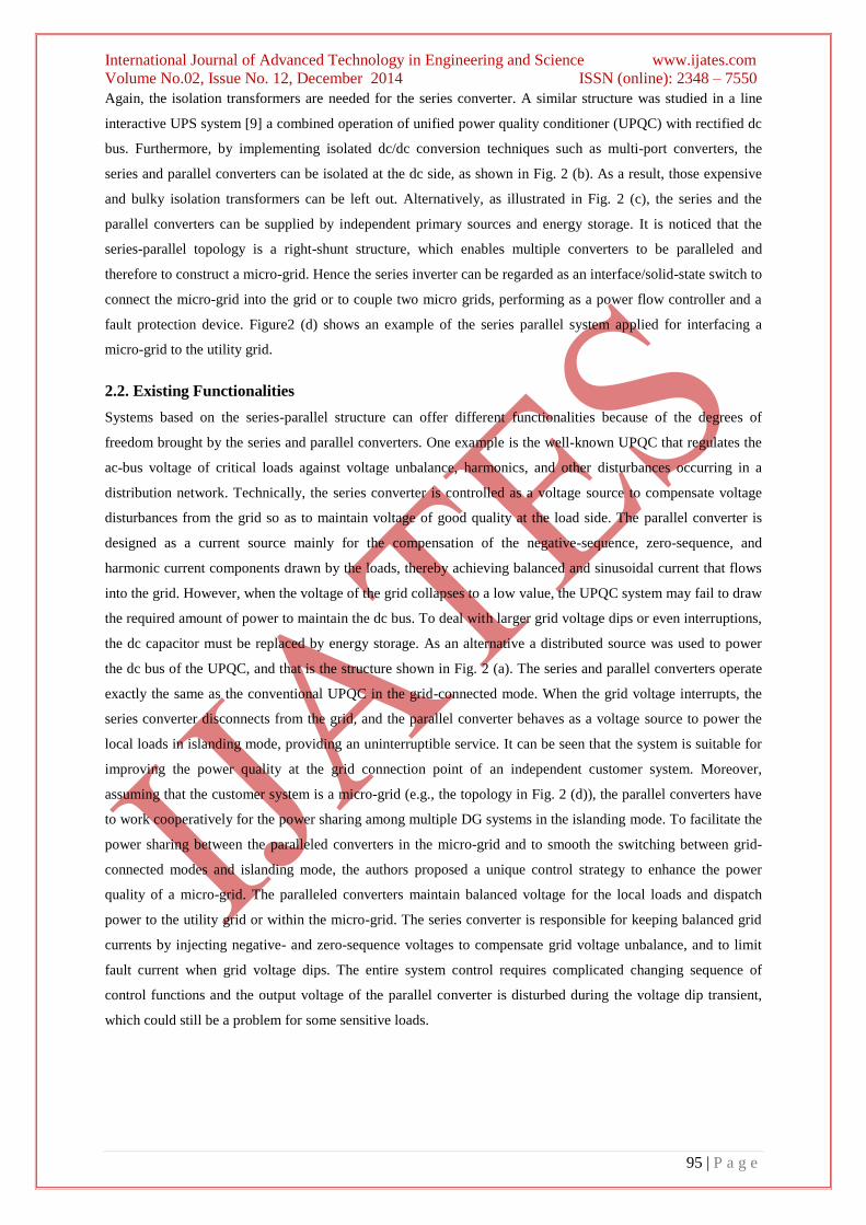
2.2. Existing Functionalities
Systems based on the series-parallel structure can offer different functionalities because of the degrees of
freedom brought by the series and parallel converters. One example is the well-known UPQC that regulates the
ac-bus voltage of critical loads against voltage unbalance, harmonics, and other disturbances occurring in a
distribution network. Technically, the series converter is controlled as a voltage source to compensate voltage
disturbances from the grid so as to maintain voltage of good quality at the load side. The parallel converter is
designed as a current source mainly for the compensation of the negative-sequence, zero-sequence, and
harmonic current components drawn by the loads, thereby achieving balanced and sinusoidal current that flows
into the grid. However, when the voltage of the grid collapses to a low value, the UPQC system may fail to draw
the required amount of power to maintain the dc bus. To deal with larger grid voltage dips or even interruptions,
the dc capacitor must be replaced by energy storage. As an alternative a distributed source was used to power
the dc bus of the UPQC, and that is the structure shown in Fig. 2 (a). The series and parallel converters operate
exactly the same as the conventional UPQC in the grid-connected mode. When the grid voltage interrupts, the
series converter disconnects from the grid, and the parallel converter behaves as a voltage source to power the
local loads in islanding mode, providing an uninterruptible service. It can be seen that the system is suitable for
improving the power quality at the grid connection point of an independent customer system. Moreover,
assuming that the customer system is a micro-grid (e.g., the topology in Fig. 2 (d)), the parallel converters have
to work cooperatively for the power sharing among multiple DG systems in the islanding mode. To facilitate the
power sharing between the paralleled converters in the micro-grid and to smooth the switching between grid-
connected modes and islanding mode, the authors proposed a unique control strategy to enhance the power
quality of a micro-grid. The paralleled converters maintain balanced voltage for the local loads and dispatch
power to the utility grid or within the micro-grid. The series converter is responsible for keeping balanced grid
currents by injecting negative- and zero-sequence voltages to compensate grid voltage unbalance, and to limit
fault current when grid voltage dips. The entire system control requires complicated changing sequence of
control functions and the output voltage of the parallel converter is disturbed during the voltage dip transient,
which could still be a problem for some sensitive loads.
International Journal of Advanced Technology in Engineering and Science www.ijates.com
Volume No.02, Issue No. 12, December 2014 ISSN (online): 2348 – 7550
96 | P a g e
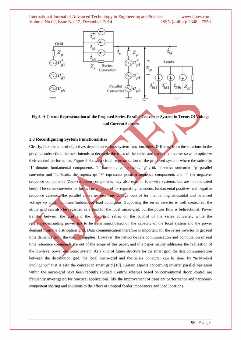
Fig.3. A Circuit Representation of the Proposed Series-Parallel Converter System In Terms Of Voltage
and Current Sources
2.3 Reconfiguring System Functionalities
Clearly, flexible control objectives depend on various system functionalities. Differing from the solutions in the
previous subsection, the next intends to decouple the roles of the series and parallel converter so as to optimize
their control performance. Figure 3 shows a circuit representation of the proposed system, where the subscript
„1‟ denotes fundamental components, „h‟-harmonic components, „g‟-grid, „s‟-series converter, „p‟-parallel
converter and „ld‟-loads; the superscript „+‟ represents positive-sequence components and „-‟ the negative-
sequence components (Zero-sequence components may also exist in four-wire systems, but are not indicated
here). The series converter performs current control for regulating harmonic, fundamental positive- and negative
sequence currents; the parallel converter performs voltage control for maintaining sinusoidal and balanced
voltage vp under nonlinear/unbalanced load conditions. Supposing the series inverter is well controlled, the
utility grid can also be regarded as a load for the local micro-grid, but the power flow is bidirectional. Power
transfer between the grid and the local grid relies on the control of the series converter, while the
reference/demanding power has to be determined based on the capacity of the local system and the power
demand from the distribution grid. Data communication therefore is important for the series inverter to get real
time demands from the user or supplier. However, the network-scale communication and computation of real
time reference commands are out of the scope of this paper, and this paper mainly addresses the realization of
the low-level power electronic system. As a kind of future structure for the smart grid, the data communication
between the distribution grid, the local micro-grid and the series converter can be done by “networked
intelligence” that is also the concept in smart grid [10]. Certain aspects concerning inverter parallel operation
within the micro-grid have been recently studied. Control schemes based on conventional droop control are
frequently investigated for practical applications, like the improvement of transient performance and harmonic-
component sharing and solutions to the effect of unequal feeder impedances and load locations.
International Journal of Advanced Technology in Engineering and Science www.ijates.com
Volume No.02, Issue No. 12, December 2014 ISSN (online): 2348 – 7550
97 | P a g e
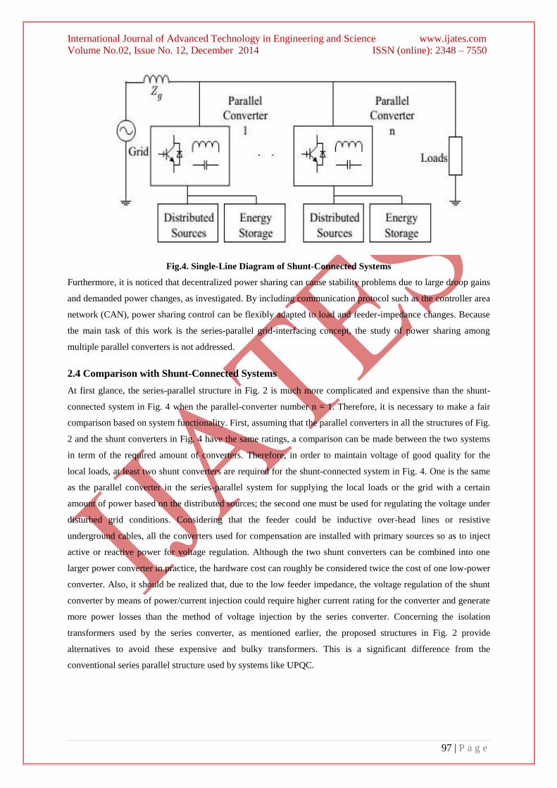
Fig.4. Single-Line Diagram of Shunt-Connected Systems
Furthermore, it is noticed that decentralized power sharing can cause stability problems due to large droop gains
and demanded power changes, as investigated. By including communication protocol such as the controller area
network (CAN), power sharing control can be flexibly adapted to load and feeder-impedance changes. Because
the main task of this work is the series-parallel grid-interfacing concept, the study of power sharing among
multiple parallel converters is not addressed.
2.4 Comparison with Shunt-Connected Systems
At first glance, the series-parallel structure in Fig. 2 is much more complicated and expensive than the shunt-
connected system in Fig. 4 when the parallel-converter number n = 1. Therefore, it is necessary to make a fair
comparison based on system functionality. First, assuming that the parallel converters in all the structures of Fig.
2 and the shunt converters in Fig. 4 have the same ratings, a comparison can be made between the two systems
in term of the required amount of converters. Therefore, in order to maintain voltage of good quality for the
local loads, at least two shunt converters are required for the shunt-connected system in Fig. 4. One is the same
as the parallel converter in the series-parallel system for supplying the local loads or the grid with a certain
amount of power based on the distributed sources; the second one must be used for regulating the voltage under
disturbed grid conditions. Considering that the feeder could be inductive over-head lines or resistive
underground cables, all the converters used for compensation are installed with primary sources so as to inject
active or reactive power for voltage regulation. Although the two shunt converters can be combined into one
larger power converter in practice, the hardware cost can roughly be considered twice the cost of one low-power
converter. Also, it should be realized that, due to the low feeder impedance, the voltage regulation of the shunt
converter by means of power/current injection could require higher current rating for the converter and generate
more power losses than the method of voltage injection by the series converter. Concerning the isolation
transformers used by the series converter, as mentioned earlier, the proposed structures in Fig. 2 provide
alternatives to avoid these expensive and bulky transformers. This is a significant difference from the
conventional series parallel structure used by systems like UPQC.
International Journal of Advanced Technology in Engineering and Science www.ijates.com
Volume No.02, Issue No. 12, December 2014 ISSN (online): 2348 – 7550
98 | P a g e
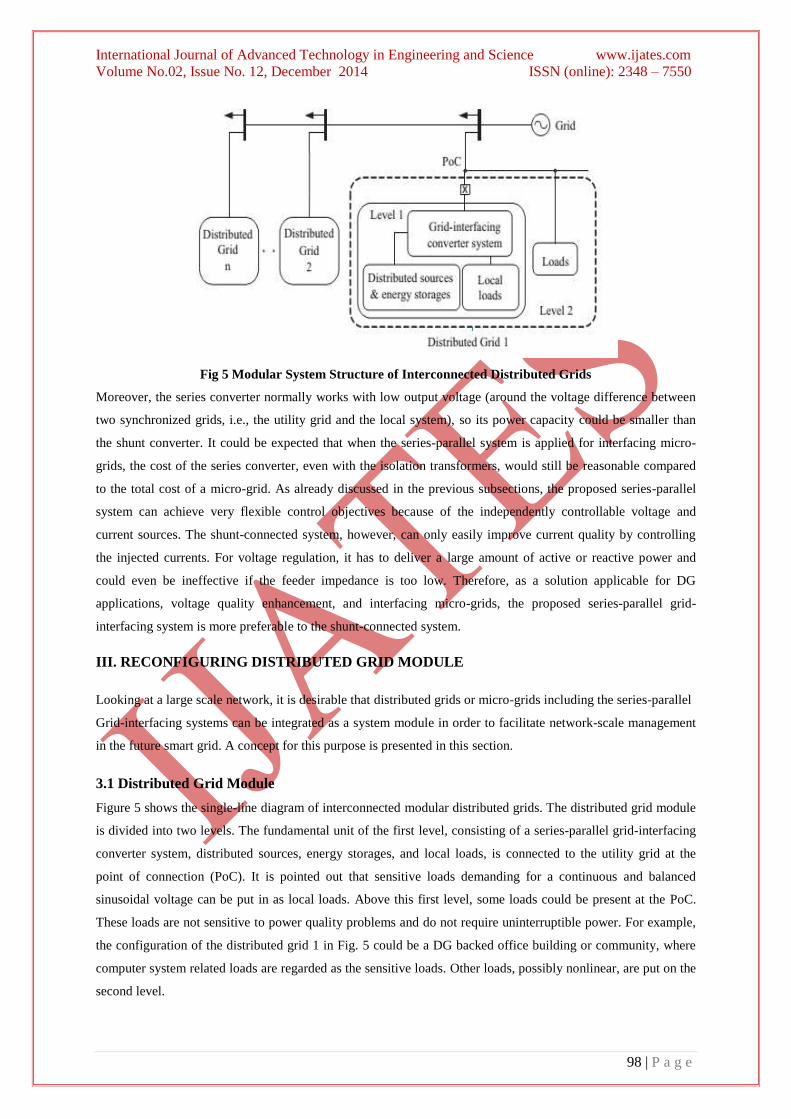
Fig 5 Modular System Structure of Interconnected Distributed Grids
Moreover, the series converter normally works with low output voltage (around the voltage difference between
two synchronized grids, i.e., the utility grid and the local system), so its power capacity could be smaller than
the shunt converter. It could be expected that when the series-parallel system is applied for interfacing micro-
grids, the cost of the series converter, even with the isolation transformers, would still be reasonable compared
to the total cost of a micro-grid. As already discussed in the previous subsections, the proposed series-parallel
system can achieve very flexible control objectives because of the independently controllable voltage and
current sources. The shunt-connected system, however, can only easily improve current quality by controlling
the injected currents. For voltage regulation, it has to deliver a large amount of active or reactive power and
could even be ineffective if the feeder impedance is too low. Therefore, as a solution applicable for DG
applications, voltage quality enhancement, and interfacing micro-grids, the proposed series-parallel grid-
interfacing system is more preferable to the shunt-connected system.
III. RECONFIGURING DISTRIBUTED GRID MODULE
Looking at a large scale network, it is desirable that distributed grids or micro-grids including the series-parallel
Grid-interfacing systems can be integrated as a system module in order to facilitate network-scale management
in the future smart grid. A concept for this purpose is presented in this section.
3.1 Distributed Grid Module
Figure 5 shows the single-line diagram of interconnected modular distributed grids. The distributed grid module
is divided into two levels. The fundamental unit of the first level, consisting of a series-parallel grid-interfacing
converter system, distributed sources, energy storages, and local loads, is connected to the utility grid at the
point of connection (PoC). It is pointed out that sensitive loads demanding for a continuous and balanced
sinusoidal voltage can be put in as local loads. Above this first level, some loads could be present at the PoC.
These loads are not sensitive to power quality problems and do not require uninterruptible power. For example,
the configuration of the distributed grid 1 in Fig. 5 could be a DG backed office building or community, where
computer system related loads are regarded as the sensitive loads. Other loads, possibly nonlinear, are put on the
second level.
International Journal of Advanced Technology in Engineering and Science www.ijates.com
Volume No.02, Issue No. 12, December 2014 ISSN (online): 2348 – 7550
99 | P a g e
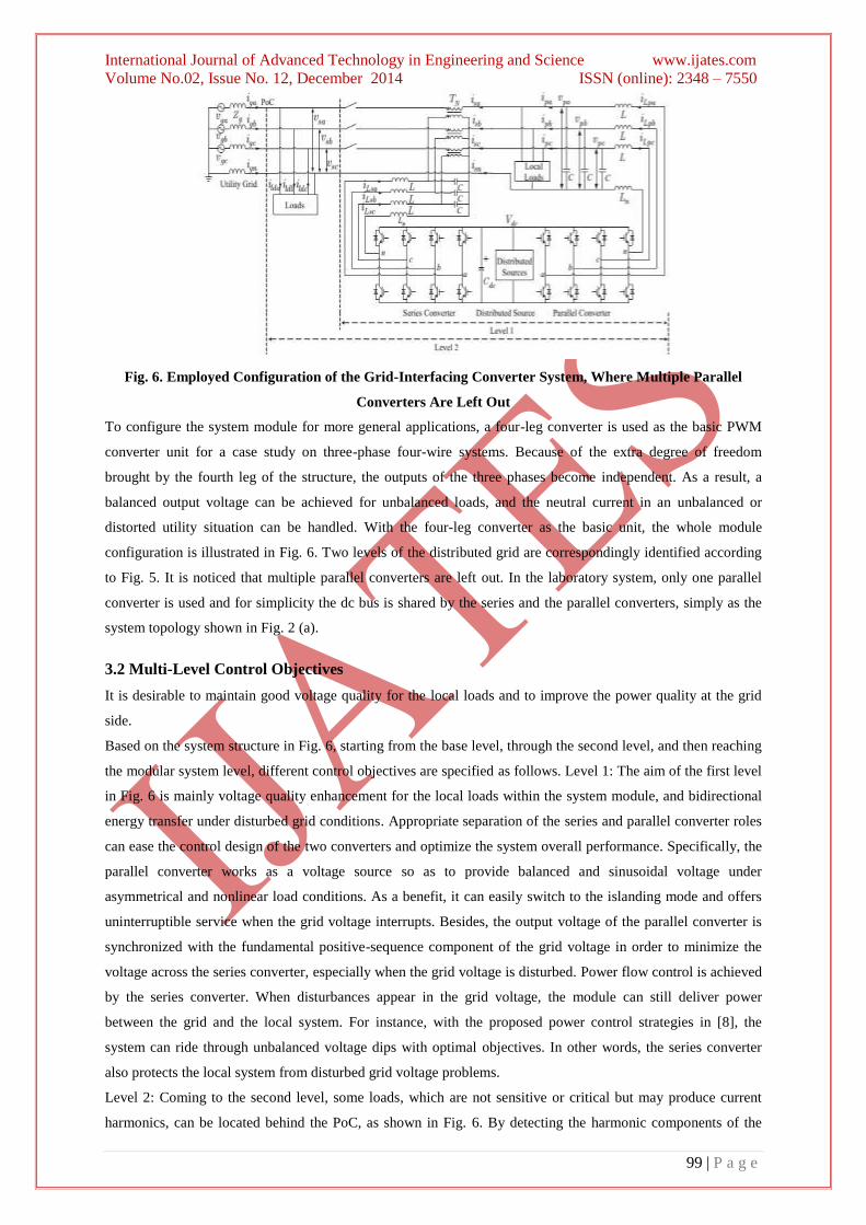
Fig. 6. Employed Configuration of the Grid-Interfacing Converter System, Where Multiple Parallel
Converters Are Left Out
To configure the system module for more general applications, a four-leg converter is used as the basic PWM
converter unit for a case study on three-phase four-wire systems. Because of the extra degree of freedom
brought by the fourth leg of the structure, the outputs of the three phases become independent. As a result, a
balanced output voltage can be achieved for unbalanced loads, and the neutral current in an unbalanced or
distorted utility situation can be handled. With the four-leg converter as the basic unit, the whole module
configuration is illustrated in Fig. 6. Two levels of the distributed grid are correspondingly identified according
to Fig. 5. It is noticed that multiple parallel converters are left out. In the laboratory system, only one parallel
converter is used and for simplicity the dc bus is shared by the series and the parallel converters, simply as the
system topology shown in Fig. 2 (a).
3.2 Multi-Level Control Objectives
It is desirable to maintain good voltage quality for the local loads and to improve the power quality at the grid
side.
Based on the system structure in Fig. 6, starting from the base level, through the second level, and then reaching
the modular system level, different control objectives are specified as follows. Level 1: The aim of the first level
in Fig. 6 is mainly voltage quality enhancement for the local loads within the system module, and bidirectional
energy transfer under disturbed grid conditions. Appropriate separation of the series and parallel converter roles
can ease the control design of the two converters and optimize the system overall performance. Specifically, the
parallel converter works as a voltage source so as to provide balanced and sinusoidal voltage under
asymmetrical and nonlinear load conditions. As a benefit, it can easily switch to the islanding mode and offers
uninterruptible service when the grid voltage interrupts. Besides, the output voltage of the parallel converter is
synchronized with the fundamental positive-sequence component of the grid voltage in order to minimize the
voltage across the series converter, especially when the grid voltage is disturbed. Power flow control is achieved
by the series converter. When disturbances appear in the grid voltage, the module can still deliver power
between the grid and the local system. For instance, with the proposed power control strategies in [8], the
system can ride through unbalanced voltage dips with optimal objectives. In other words, the series converter
also protects the local system from disturbed grid voltage problems.
Level 2: Coming to the second level, some loads, which are not sensitive or critical but may produce current
harmonics, can be located behind the PoC, as shown in Fig. 6. By detecting the harmonic components of the
International Journal of Advanced Technology in Engineering and Science www.ijates.com
Volume No.02, Issue No. 12, December 2014 ISSN (online): 2348 – 7550
100 | P a g e
load current ild a, b, c, the series-parallel system can act as an active filter to prevent low order current
harmonics from flowing through the utility grid, while high-order harmonic currents can be easily removed by
adding passive filters if necessary.
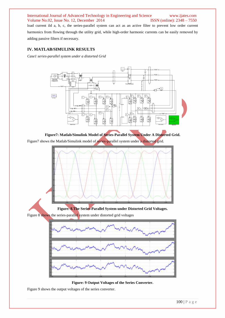
IV. MATLAB/SIMULINK RESULTS
Case1 series-parallel system under a distorted Grid
Figure7: Matlab/Simulink Model of Series-Parallel System Under A Distorted Grid.
Figure7 shows the Matlab/Simulink model of series-parallel system under a distorted grid.
Figure: 8.The Series-Parallel System under Distorted Grid Voltages.
Figure 8 shows the series-parallel system under distorted grid voltages
Figure: 9 Output Voltages of the Series Converter.
Figure 9 shows the output voltages of the series converter.
International Journal of Advanced Technology in Engineering and Science www.ijates.com
Volume No.02, Issue No. 12, December 2014 ISSN (online): 2348 – 7550
101 | P a g e
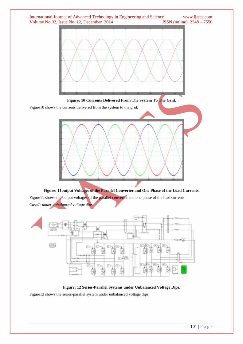
Figure: 10 Currents Delivered From The System To The Grid.
Figure10 shows the currents delivered from the system to the grid.
Figure: 11output Voltages of the Parallel Converter and One Phase of the Load Currents.
Figure11 shows the output voltages of the parallel converter and one phase of the load currents.
Case2: under unbalanced voltage dips
Figure: 12 Series-Parallel Systems under Unbalanced Voltage Dips.
Figure12 shows the series-parallel system under unbalanced voltage dips.
International Journal of Advanced Technology in Engineering and Science www.ijates.com
Volume No.02, Issue No. 12, December 2014 ISSN (online): 2348 – 7550
102 | P a g e
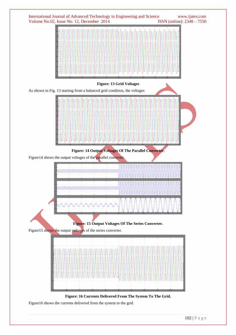
Figure: 13 Grid Voltages
As shown in Fig. 13 starting from a balanced grid condition, the voltages
Figure: 14 Output Voltages Of The Parallel Converter.
Figure14 shows the output voltages of the parallel converter.
Figure: 15 Output Voltages Of The Series Converter.
Figure15 shows the output voltages of the series converter.
Figure: 16 Currents Delivered From The System To The Grid.
Figure16 shows the currents delivered from the system to the grid.
International Journal of Advanced Technology in Engineering and Science www.ijates.com
Volume No.02, Issue No. 12, December 2014 ISSN (online): 2348 – 7550
103 | P a g e
V.CONCLUSION
This paper has introduced system-level concept and implementation aspects aiming at grid-interfacing
architecture in the future grid with enhanced voltage quality. A group of series-parallel grid-interfacing system
topologies have been proposed. They are suitable for DG applications, voltage quality improvement, and power
transfer. With the reconfigurable functionalities, the proposed systems have been compared with conventional
series-parallel systems and shunt-connected systems, showing flexible applicability. The entire control design of
the series and parallel converters has been presented, where the main design aspects of the controllers have been
highlighted. By defining multi-level control objectives for the system module, it has been shown that the
proposed system can ride through grid disturbances, maintain good-quality voltage and achieve flexible power
control.
REFERENCES
[1] IEEE guide for service to equipment sensitive to momentary voltage disturbances, IEEE Std. 1250-1995,
1995.
[2] D.B. Vannoy, M.F. McGranaghan, M. Halpin, W.A. Moncrief, and D. Sabin, “Roadmap for power-quality
standards development, ”IEEE Trans. Ind. Appl., vol. 43, no. 2, pp. 412-421, Mar./Apr. 2007.
[3] S. Massound Amin and B.F. Wollenberg, “Toward a smart grid: Power delivery for the 21st century,
”IEEE Power Energy Mag., vol. 3, no. 5, pp. 34-41, Sep./Oct. 2005.
[4] L. Freris and D. Infield, Renewable energy in power systems. Wiley, 2008.
[5] G. Joos, B.-T. Ooi, D. McGillis, F.D. Galiana, and R. Marceau, “The potential of distributed generation to
provide ancillary services,” in Proc. IEEE Power Eng. Soc. Summer Meeting, Jun. 2000.
[6] K.J.P. Macken, K. Vanthournout, J. Van den Key bus, G. Deconinck, and R.J.M. Belmans, “Distributed
control of renewable generation units with integrated active filter,” IEEE Trans. Power Electron., vol. 19,
no. 5, pp. 1353-1360, Sep. 2004.
[7] F.Wang, J. L. Duarte, and M. A.M. Hendrix, “Control of grid-interfacing inverters with integrated voltage
unbalance correction,” in Proc. IEEE Power Electronics Specialists Conference, 2008, pp. 310-316.
[8] F. Wang, J.L. Duarte, and M.A.M. Hendrix, “Pliant active and reactive power control for grid-interactive
converters under unbalanced voltage dips, ”IEEE Transactions on Power Electronics, in press, 2010.
[9] J.M. Guerrero, L.G.D. Vicuna, and J. Uceda, “Uninterruptible power supply systems provide protection,”
IEEE Ind. Electron. Mag., vol. 1, no. 1, pp. 28-38, Spring 2007.
[10] H. Farhangi, “The path of the smart grid,” IEEE Power Energy Mag., vol. 8, no. 1, pp. 18-28, Jan./Feb.
2010.
Recommended