ServiceTips and Information
Fuel supply for engines with Fuel Injection Systems
PIERBURG

1
2
Introduction
An internal combustion engine requires fuel in order to run, and motor vehicles are thus equipped witha fuel system that keeps the engine supplied with the correct amount of fuel for all operatingcircumstances.
Outside factors and wear can lead to faults, and this is when a reliable servicing programme becomesnecessary.
This brochure is intended to provide problem-solving tips and information for everyday use whenservicing fuel injection systems.
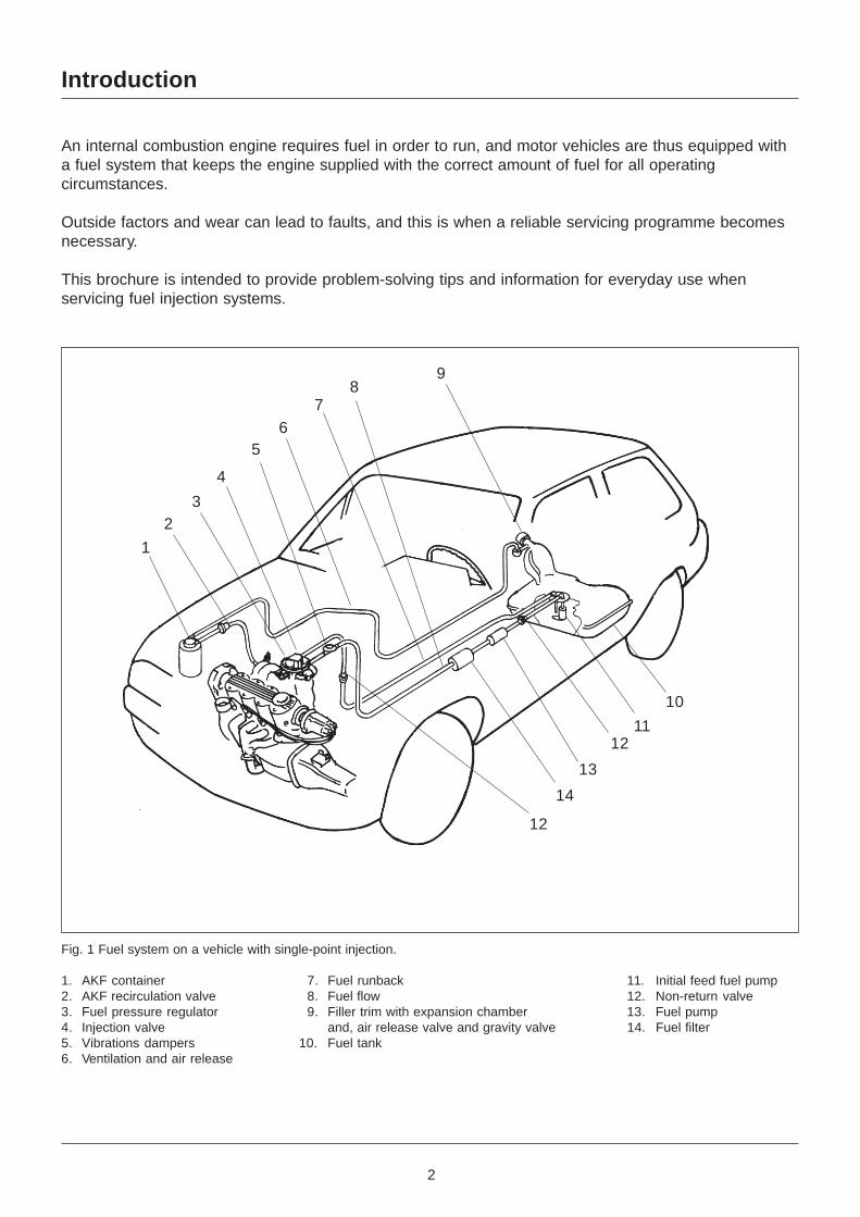
Fig. 1 Fuel system on a vehicle with single-point injection.
1. AKF container 7. Fuel runback 11. Initial feed fuel pump2. AKF recirculation valve 8. Fuel flow 12. Non-return valve3. Fuel pressure regulator 9. Filler trim with expansion chamber 13. Fuel pump4. Injection valve and, air release valve and gravity valve 14. Fuel filter5. Vibrations dampers 10. Fuel tank6. Ventilation and air release
1
23
4
56
78
9
12
10
1112
13
14
3
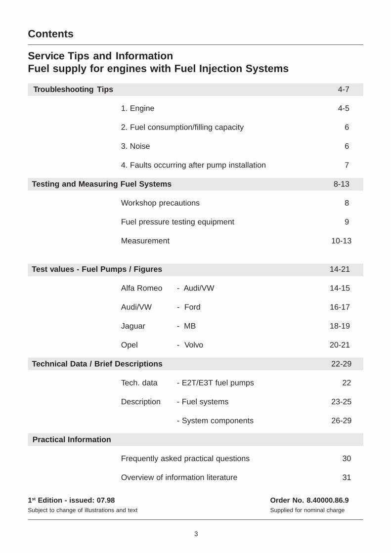
Contents
Service Tips and InformationFuel supply for engines with Fuel Injection Systems
Troubleshooting Tips 4-7
1. Engine 4-5
2. Fuel consumption/filling capacity 6
3. Noise 6
4. Faults occurring after pump installation 7
Testing and Measuring Fuel Systems 8-13
Workshop precautions 8
Fuel pressure testing equipment 9
Measurement 10-13
Test values - Fuel Pumps / Figures 14-21
Alfa Romeo - Audi/VW 14-15
Audi/VW - Ford 16-17
Jaguar - MB 18-19
Opel - Volvo 20-21
Technical Data / Brief Descriptions 22-29
Tech. data - E2T/E3T fuel pumps 22
Description - Fuel systems 23-25
- System components 26-29
Practical Information
Frequently asked practical questions 30
Overview of information literature 31
1st Edition - issued: 07.98 Order No. 8.40000.86.9Subject to change of illustrations and text Supplied for nominal charge
4
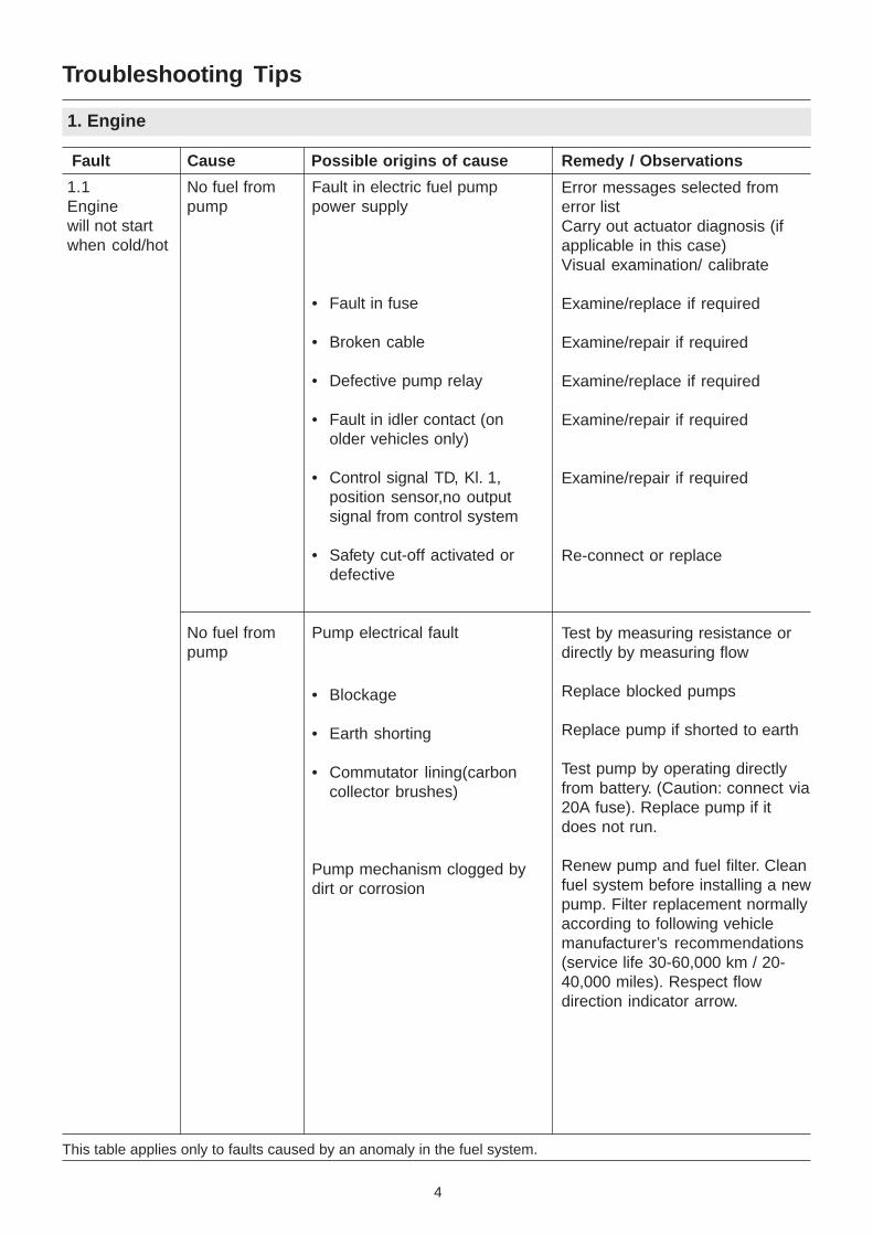
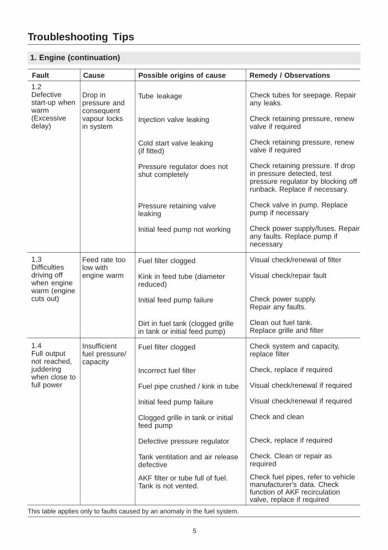
This table applies only to faults caused by an anomaly in the fuel system.
Troubleshooting Tips
1. Engine
Fault Cause Possible origins of cause Remedy / Observations
1.1Enginewill not startwhen cold/hot
No fuel frompump
No fuel frompump
Fault in electric fuel pumppower supply
• Fault in fuse
• Broken cable
• Defective pump relay
• Fault in idler contact (onolder vehicles only)
• Control signal TD, Kl. 1,position sensor,no outputsignal from control system
• Safety cut-off activated ordefective
Pump electrical fault
• Blockage
• Earth shorting
• Commutator lining(carboncollector brushes)
Pump mechanism clogged bydirt or corrosion
Error messages selected fromerror listCarry out actuator diagnosis (ifapplicable in this case)Visual examination/ calibrate
Examine/replace if required
Examine/repair if required
Examine/replace if required
Examine/repair if required
Examine/repair if required
Re-connect or replace
Test by measuring resistance ordirectly by measuring flow
Replace blocked pumps
Replace pump if shorted to earth
Test pump by operating directlyfrom battery. (Caution: connect via20A fuse). Replace pump if itdoes not run.
Renew pump and fuel filter. Cleanfuel system before installing a newpump. Filter replacement normallyaccording to following vehiclemanufacturer’s recommendations(service life 30-60,000 km / 20-40,000 miles). Respect flowdirection indicator arrow.
5
This table applies only to faults caused by an anomaly in the fuel system.
Troubleshooting Tips
1. Engine (continuation)
Fault Cause Possible origins of cause Remedy / Observations
Drop inpressure andconsequentvapour locksin system
Feed rate toolow withengine warm
Insufficientfuel pressure/capacity
Check tubes for seepage. Repairany leaks.
Check retaining pressure, renewvalve if required
Check retaining pressure, renewvalve if required
Check retaining pressure. If dropin pressure detected, testpressure regulator by blocking offrunback. Replace if necessary.
Check valve in pump. Replacepump if necessary
Check power supply/fuses. Repairany faults. Replace pump ifnecessary
Visual check/renewal of filter
Visual check/repair fault
Check power supply.Repair any faults.
Clean out fuel tank.Replace grille and filter
Check system and capacity,replace filter
Check, replace if required
Visual check/renewal if required
Visual check/renewal if required
Check and clean
Check, replace if required
Check. Clean or repair asrequired
Check fuel pipes, refer to vehiclemanufacturer’s data. Checkfunction of AKF recirculationvalve, replace if required
1.2Defectivestart-up whenwarm(Excessivedelay)
1.3Difficultiesdriving offwhen enginewarm (enginecuts out)
1.4Full outputnot reached,judderingwhen close tofull power
Tube leakage
Injection valve leaking
Cold start valve leaking(if fitted)
Pressure regulator does notshut completely
Pressure retaining valveleaking
Initial feed pump not working
Fuel filter clogged
Kink in feed tube (diameterreduced)
Initial feed pump failure
Dirt in fuel tank (clogged grillein tank or initial feed pump)
Fuel filter clogged
Incorrect fuel filter
Fuel pipe crushed / kink in tube
Initial feed pump failure
Clogged grille in tank or initialfeed pump
Defective pressure regulator
Tank ventilation and air releasedefective
AKF filter or tube full of fuel.Tank is not vented.
6
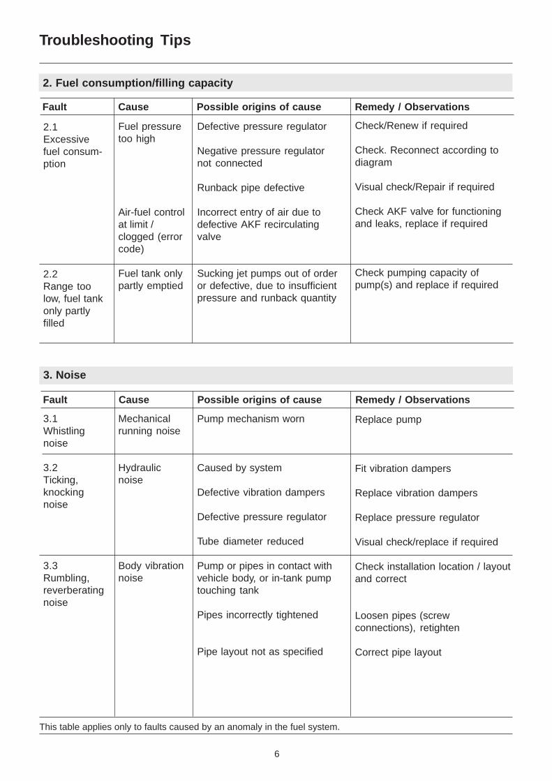
This table applies only to faults caused by an anomaly in the fuel system.
Troubleshooting Tips
2. Fuel consumption/filling capacity
Fault Cause Possible origins of cause Remedy / Observations
2.1Excessivefuel consum-ption
2.2Range toolow, fuel tankonly partlyfilled
Fuel pressuretoo high
Air-fuel controlat limit /clogged (errorcode)
Fuel tank onlypartly emptied
Defective pressure regulator
Negative pressure regulatornot connected
Runback pipe defective
Incorrect entry of air due todefective AKF recirculatingvalve
Sucking jet pumps out of orderor defective, due to insufficientpressure and runback quantity
Check/Renew if required
Check. Reconnect according todiagram
Visual check/Repair if required
Check AKF valve for functioningand leaks, replace if required
Check pumping capacity ofpump(s) and replace if required
Fault Cause Possible origins of cause Remedy / Observations
3. Noise
Replace pump
Fit vibration dampers
Replace vibration dampers
Replace pressure regulator
Visual check/replace if required
Check installation location / layoutand correct
Loosen pipes (screwconnections), retighten
Correct pipe layout
Pump mechanism worn
Caused by system
Defective vibration dampers
Defective pressure regulator
Tube diameter reduced
Pump or pipes in contact withvehicle body, or in-tank pumptouching tank
Pipes incorrectly tightened
Pipe layout not as specified
Mechanicalrunning noise
Hydraulicnoise
Body vibrationnoise
3.1Whistlingnoise
3.2Ticking,knockingnoise
3.3Rumbling,reverberatingnoise
7
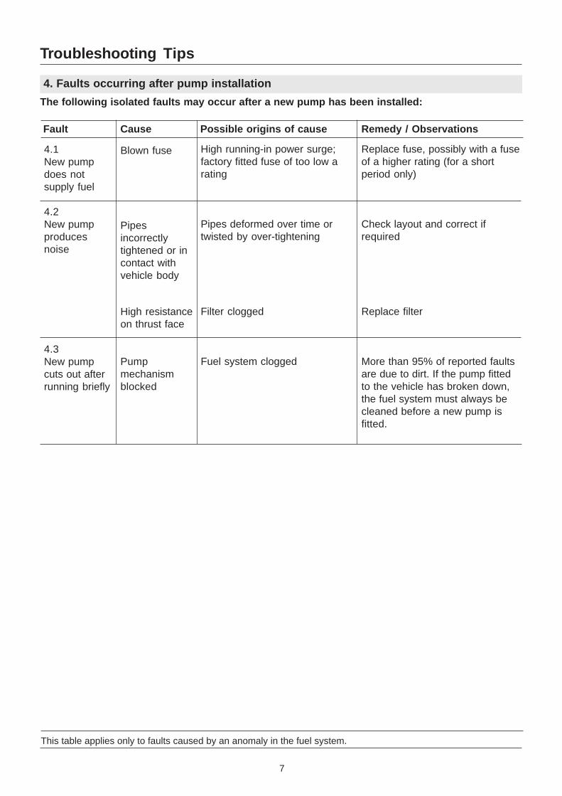
This table applies only to faults caused by an anomaly in the fuel system.
Troubleshooting Tips
4. Faults occurring after pump installation
The following isolated faults may occur after a new pump has been installed:
Fault Cause Possible origins of cause Remedy / Observations
4.1New pumpdoes notsupply fuel
4.2New pumpproducesnoise
4.3New pumpcuts out afterrunning briefly
Replace fuse, possibly with a fuseof a higher rating (for a shortperiod only)
Check layout and correct ifrequired
Replace filter
More than 95% of reported faultsare due to dirt. If the pump fittedto the vehicle has broken down,the fuel system must always becleaned before a new pump isfitted.
High running-in power surge;factory fitted fuse of too low arating
Pipes deformed over time ortwisted by over-tightening
Filter clogged
Fuel system clogged
Blown fuse
Pipesincorrectlytightened or incontact withvehicle body
High resistanceon thrust face
Pumpmechanismblocked
8
Check and measuring the fuel system
Important notes
GeneralAll vehicle manufacturers have various types of injection systems. These instructions are ageneral guide for the use of the fuel injection pressure test set. The procedures outlined hereare examples only.Always follow the vehicle manufacturer's recommendations and instructions.Test data can be taken from the repair instructions of the vehicle manufacturer, the fuel chartand manual or the injection manuals published by Autodata.
SafetyAttention• Vehicle emissions and fuel vapours are harmful to your health! When working in closed
areas, always activate the ventilation or vapour evacuation system.• Fuel and fuel vapour are easily inflammable. Therefore don't smoke and avoid any open
flames or sparks. Keep a fire extinguisher in the vicinity ready for use.• When working aroud the engine compartment, pay particular attention to the following:
- rotating parts (ventilator, belt, alternator etc.)- hot components (exhaust gas manifold, engine, radiator)- components that carry an electrical current (cable, ignition system, battery)- tools: don't leyve any tool in the engine compartment
• In order to prevent any damage, connect or disconnect electrical lines of the ignition andinjection system only when the ignition is switched off.
• Fuel injection systems are under pressure. Disconnect connections and hoses only when theengine is not running and the ignition is switched off. Collect any fuel that leaks. Wearprotective glasses if necessary.
• Before starting to work on a vehicle make sure that no gear is engaged and the parking brakeis pulled.
• After completing your work on the fuel system, always check for leakage.
CleanlinessContamination, in particular in injection systems, causes malfunctions. In order to prevent thisfrom happening, the following recommendations should be followed:• Thoroughly clean the area and the environment of a connection before removing it.• Place removed components in a clean arey and cover them properly.• When interrupting your work, cover/close up any open or desassembled components.• Install only clean components.• Remove any packing or transprotation containers, for instance plugs in new fuel pumps, only
immediately before installation of the component.• Do not use compressed air when working with open or exposed fuel systems.• In case of any damage that has been caused by contamination, clean the fuel system before
installing any new components or equipment.
MiscellaneousIn case of faults in the fuel supply system and before measuring any pressure, do the following:• Check the battery voltage and the fuses.• Check whether or not the fuel pump starts running when switching the ignition on.• Check fuel lines for proper placement.
9
Check and measuring the fuel system
Fuel injection pressure test set
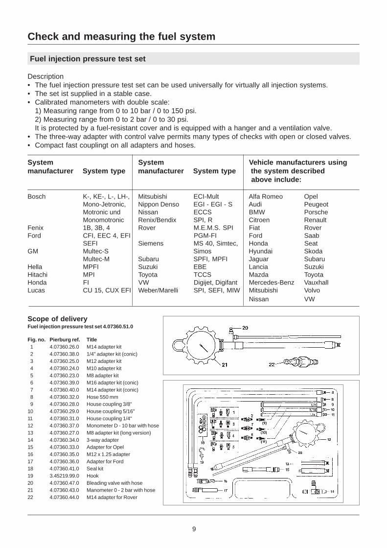
Description• The fuel injection pressure test set can be used universally for virtually all injection systems.• The set ist supplied in a stable case.• Calibrated manometers with double scale:
1) Measuring range from 0 to 10 bar / 0 to 150 psi.2) Measuring range from 0 to 2 bar / 0 to 30 psi.It is protected by a fuel-resistant cover and is equipped with a hanger and a ventilation valve.
• The three-way adapter with control valve permits many types of checks with open or closed valves.• Compact fast couplingt on all adapters and hoses.
System System Vehicle manufacturers usingmanufacturer System type manufacturer System type the system described
above include:
Bosch K-, KE-, L-, LH-, Mitsubishi ECI-Mult Alfa Romeo OpelMono-Jetronic, Nippon Denso EGI - EGI - S Audi PeugeotMotronic und Nissan ECCS BMW PorscheMonomotronic Renix/Bendix SPI, R Citroen Renault
Fenix 1B, 3B, 4 Rover M.E.M.S. SPI Fiat RoverFord CFI, EEC 4, EFI PGM-FI Ford Saab
SEFI Siemens MS 40, Simtec, Honda SeatGM Multec-S Simos Hyundai Skoda
Multec-M Subaru SPFI, MPFI Jaguar SubaruHella MPFI Suzuki EBE Lancia SuzukiHitachi MPI Toyota TCCS Mazda ToyotaHonda FI VW Digijet, Digifant Mercedes-Benz VauxhallLucas CU 15, CUX EFI Weber/Marelli SPI, SEFI, MIW Mitsubishi Volvo
Nissan VW
Scope of deliveryFuel injection pressure test set 4.07360.51.0
Fig. no. Pierburg ref. Title 1 4.07360.26.0 M14 adapter kit 2 4.07360.38.0 1/4" adapter kit (conic) 3 4.07360.25.0 M12 adapter kit 4 4.07360.24.0 M10 adapter kit 5 4.07360.23.0 M8 adapter kit 6 4.07360.39.0 M16 adapter kit (conic) 7 4.07360.40.0 M14 adapter kit (conic) 8 4.07360.32.0 Hose 550 mm 9 4.07360.28.0 House coupling 3/8"10 4.07360.29.0 House coupling 5/16"11 4.07360.31.0 House coupling 1/4"12 4.07360.37.0 Monometer D - 10 bar with hose13 4.07360.27.0 M8 adapter kit (long version)14 4.07360.34.0 3-way adapter15 4.07360.33.0 Adapter for Opel16 4.07360.35.0 M12 x 1.25 adapter17 4.07360.36.0 Adapter for Ford18 4.07360.41.0 Seal kit19 3.45219.99.0 Hook20 4.07360.47.0 Bleading valve with hose21 4.07360.43.0 Manometer 0 - 2 bar with hose22 4.07360.44.0 M14 adapter for Rover
10
Check and measuring the fuel system
Measurements
1. Measurements onvehicles with "K-Jetronic"
1.1. Main system pressure• The three-way adapter
should be installedbetween the fueldistributor and thewarm-up control unit.
• Before doing this,depressurise the system.
• In order to depressurisethe system,always remove theupper plug (upper chamberof the fueldistributor) first.
- Connection "A" towards thefuel distributor.
- Connection "B" towards thewarm-up control unit.
- Close the contorl valve onthe three-way adapter.
- Disconnect the pump relayand connect the cableconnections termial 30 andterminal 87 with an auxiliarycable with an integrated20 A fuse.Switch on the ignition. Thefuel pump should startrunning now.
- Before taking
measurements,depressurise thesystem by pressing thebutton on the bleedingvalve of the manometer.Collect the fuel leaking outof the drainage hose in asuitable container.
- Read the main systempressure on the mano-meter; for the respectivedata, refer to themanufacturer's specifiction.
1.2 Control pressure• The fuel pump should be
running.- Open the control valve "D"
on the three-way adapter.- Read the control pressure
on the manometer.- For pressures "cold" -
"warm": refer to themanufacturer'sspecification.
1.3 Retaining pressure/remaining pressure- Close the control valve "D"
on the three-way adapter.- Switch the ignition on; the
fuel pump should berunning now.
- Switch the ignition off aftera maximum of 3 to 5seconds.
- Read the retainingpressure after 10 or 20minutes. For therestpective data, refer tothe manufacturer'sspecification.
1.4 ATTENTION!Before removing the three-way adapter, depressurisethe system by pressing thebutton on the bleedingvalve. Collect any fuel lleaking through thedrainage hose in a suitablecontainer.
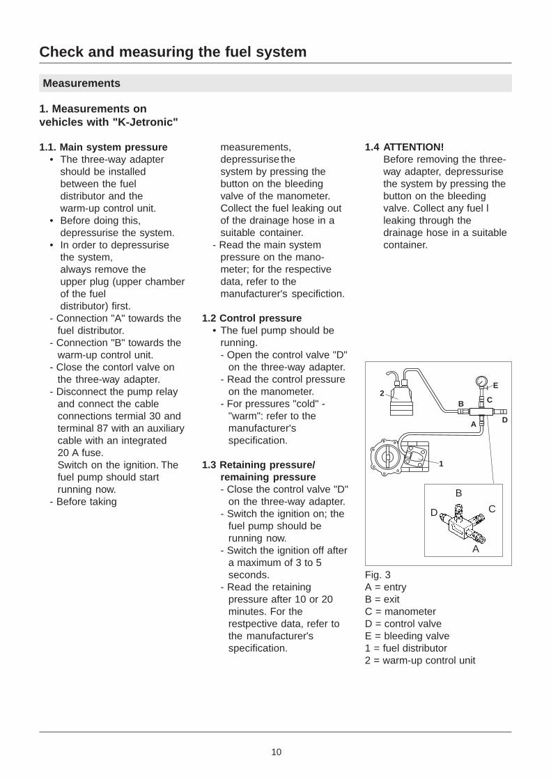
Fig. 3A = entryB = exitC = manometerD = control valveE = bleeding valve1 = fuel distributor2 = warm-up control unit
A
B
CD
E
A
2
1
C
D
B
11
Check and measuring the fuel system
Measurements
2. Measurements onvehicles with "KE-Jetronic"
2.1 Main system pressure/upper chamber pressure
• The three-way adaptershould be connected to thefuel distributor betweenupper and lower chamber.
• Before doing so, carefullyremove the upper specialconnection or theconnection towards thecold-start valve on the fueldistributor. This depres-surises the system.
- Connect connection "A" tothe special test connec-tion, in the lowerchamber of the fueldistributor.
- Connect connection "B" tothe special test connection,in the upper chamber, orthe connection of the cold-start valve, of the fueldistributor.
- Open the control valve "D"on the three-way adapter.
- Disconnect the pump relayand connect the cableconnections terminal 30and terminal 87 with anauxiliary cable with anintegrated 20A fuse.
- Switch the ignition on; the
fuel pump should berunning now.
- Before takingmeasurements,depressurise the system bypressing the button on thebleeding valve of themanometer. Collect any fuelleaking out of the drainagehose in a suitable container.
- Read the main systempressure on themanometer; for therespective data, refer to themanufacturer'sspecification.
2.2 Pressure differential/lowerchamber pressure
- Close the control valve "D"on the three-way adapter.
- Remove the multiple plugfrom the pressure actuatoron the fuel distributor.
- Switch the ignition on; thefuel pump should berunning now.
- Read the pressure differential on the manometer. Forthe respective data, refer tothe manufacturer'sspecification.
- Switch the ignition off.
2.3 Retaining pressure/remaining pressure
- Open the control valve "D"on the three-directionalvalve.
- Switch the ignition on. The
fuel pump should berunning now.
- Switch the ignition off aftermaximum of 3 to 5 seconds.
- Read the retaining pressureafter 10 or 20 minutes. Forthe respective data, refer tothe manufacturer'sspecification.
2.4 ATTENTION!Before removing the three-way adapter, depressurisethe system by pressing thebutton on the bleedingvalve. Collect any fuelleaking through thedrainage hose in a suitablecontainer.
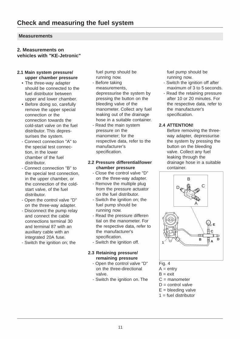
Fig. 4A = entryB = exitC = manometerD = control valveE = bleeding valve1 = fuel distributor
A
B
CD
1
E
A
C
DB
12
Check and measuring the fuel system
Measurements
3. Measurements on vehicleswith electronic multi-pointinjection systems, like Bosch-L/LH-Jetronic, Motronic, MPI,HMPI, EFI or Digifant.
• With these systems, the testmethod ist mostly identical.
• Some vehicles are providedwith special test connectionson the fuel distribution tube infornt of the main systempressure regulator.
3.1 Checking the main systempressure• Carefully disconnect the fuel
line at a suitable location. Thisdepressurises the system.- Connect connection "A" onthe three-way adapter in thedirection of the filter.- Connect connection "B" on
the three-way adapter in thedirection of the injectors/fueldistribution tube, controlvlave "D" open.
- If the vehicle is provided witha test connection, only theconnection "In" on the three-way adapter ist used. In thiscase the control valveremains closed.
• The main system pressurecan be checked with theengine either running or notrunning.
3.1.1 With the engine notrunning.
- Disconnnect the pump relayand connect the cableconnections terminal 30 andterminal 87 with an auxiliarycable, including a fuse(20A).
- Switch the ignition on; thefuel pump should be runningnow.
- Beforetaking
measurements,depressurise the system bypressing the button on thebleeding valve of themanometer. Collect any fuelleaking out of the drainagehose in a suitable container.
- Read the main systempressure on th manometer;for data, refer to themanufacturer's specification.
3.1.2 With the engine running- Leave the engine running:read the main systempressure on the manometer.For the respective data,refer to the manufacturer'sspecification.
3.2 Retaining pressure/remaining pressure
- Leave the fuel pump or theengine running; switch offafter 3 to 5 seconds.
- Read the retaining pressureaccording to themanufacturer's specificationin various time intervalls(e.g. 3 minutes and 5minutes) on the manometer.
3.3 Checking the main systempressure regulator• At the end of the fuel
distribution tube you will findthe main system pressureregulator. If it is suspectedthat the main system pressureis not correct, it should bechecked as follows:- Leave the engine of the fuelpump running; read themain system pressure.
- Close the recirculation line;the pressure in the systemshould increase sharply;now measure the "deliverypressure".
- Read the level on themanometer and comparewith the manufacturer'sspecification (if the pumpinpressure is indicated).
- Open the recirculation lineagain.
- Disconnect the vacuumhose on the diaphragm sideof the pressure regulator.Read the pressure andrecord the respective value.
- Using a manual vacuumpump, set a pressure differential of 500 mbar - themanin system pressureshould fall. Read themeasuring value andcompare it with the previouspressure value. Pressuredifferential approximatly 0.5bar.
3.4 ATTENTION!Before removing the three-wayadapter, depressurise thesystem by pressing the buttonon the bleeding valve. Collectany fuel leaking through thedrainage hose in a suitablecontainer.
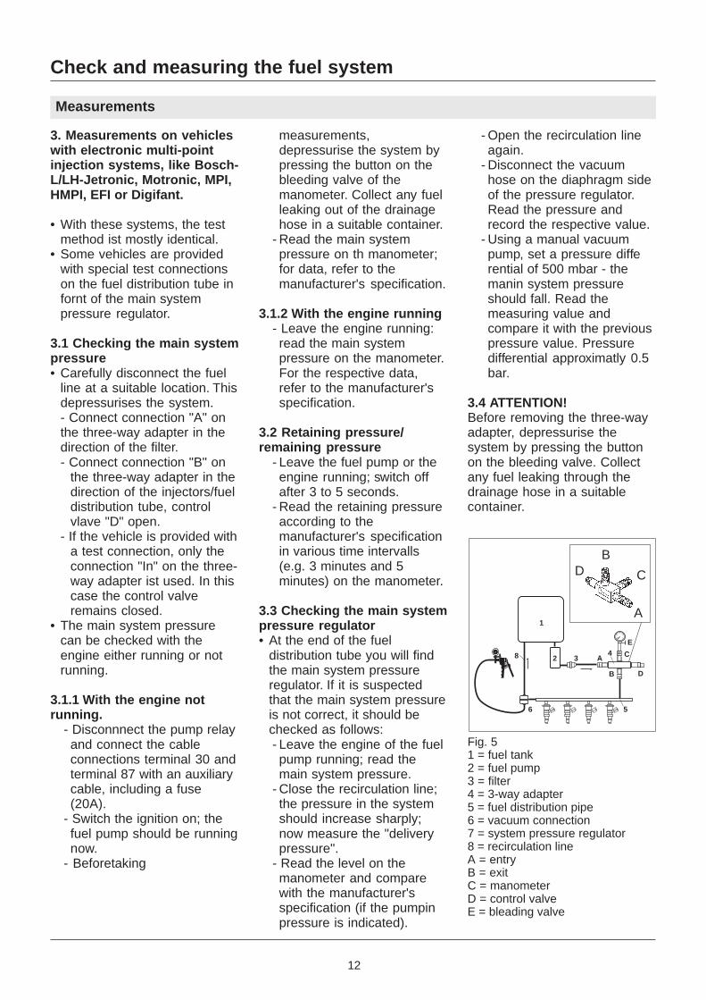
Fig. 51 = fuel tank2 = fuel pump3 = filter4 = 3-way adapter5 = fuel distribution pipe6 = vacuum connection7 = system pressure regulator8 = recirculation lineA = entryB = exitC = manometerD = control valveE = bleading valve
1
8 2 34
E
A C
DB
56
A
C
BD
13
Check and measuring the fuel system
Measurements
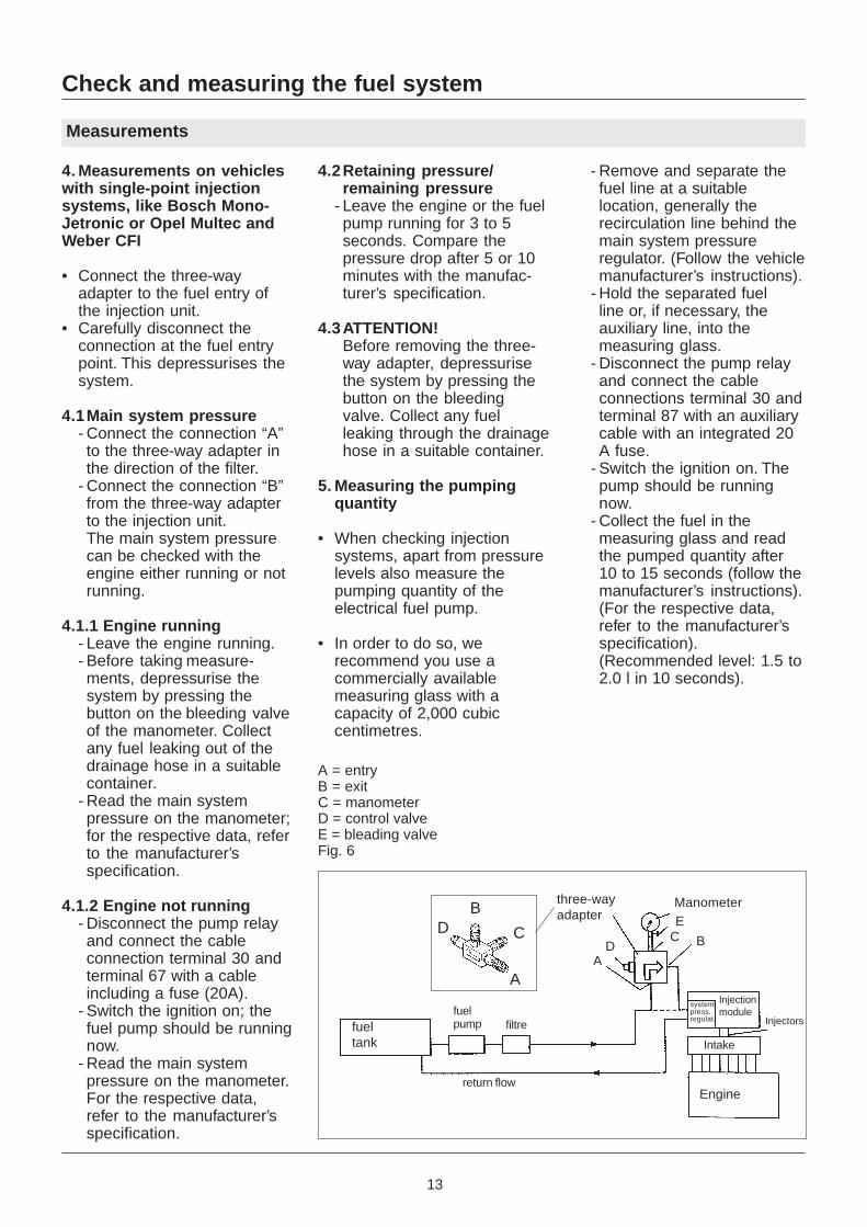
4. Measurements on vehicleswith single-point injectionsystems, like Bosch Mono-Jetronic or Opel Multec andWeber CFI
• Connect the three-wayadapter to the fuel entry ofthe injection unit.
• Carefully disconnect theconnection at the fuel entrypoint. This depressurises thesystem.
4.1Main system pressure- Connect the connection “A”to the three-way adapter inthe direction of the filter.
- Connect the connection “B”from the three-way adapterto the injection unit.The main system pressurecan be checked with theengine either running or notrunning.
4.1.1 Engine running- Leave the engine running.- Before taking measure-ments, depressurise thesystem by pressing thebutton on the bleeding valveof the manometer. Collectany fuel leaking out of thedrainage hose in a suitablecontainer.
- Read the main systempressure on the manometer;for the respective data, referto the manufacturer’sspecification.
4.1.2 Engine not running- Disconnect the pump relayand connect the cableconnection terminal 30 andterminal 67 with a cableincluding a fuse (20A).
- Switch the ignition on; thefuel pump should be runningnow.
- Read the main systempressure on the manometer.For the respective data,refer to the manufacturer’sspecification.
4.2Retaining pressure/remaining pressure
- Leave the engine or the fuelpump running for 3 to 5seconds. Compare thepressure drop after 5 or 10minutes with the manufac-turer’s specification.
4.3ATTENTION!Before removing the three-way adapter, depressurisethe system by pressing thebutton on the bleedingvalve. Collect any fuelleaking through the drainagehose in a suitable container.
5. Measuring the pumpingquantity
• When checking injectionsystems, apart from pressurelevels also measure thepumping quantity of theelectrical fuel pump.
• In order to do so, werecommend you use acommercially availablemeasuring glass with acapacity of 2,000 cubiccentimetres.
- Remove and separate thefuel line at a suitablelocation, generally therecirculation line behind themain system pressureregulator. (Follow the vehiclemanufacturer’s instructions).
- Hold the separated fuelline or, if necessary, theauxiliary line, into themeasuring glass.
- Disconnect the pump relayand connect the cableconnections terminal 30 andterminal 87 with an auxiliarycable with an integrated 20A fuse.
- Switch the ignition on. Thepump should be runningnow.
- Collect the fuel in themeasuring glass and readthe pumped quantity after10 to 15 seconds (follow themanufacturer’s instructions).(For the respective data,refer to the manufacturer’sspecification).(Recommended level: 1.5 to2.0 l in 10 seconds).
A
C
BD
ManometerE
C B
AD
three-wayadapter
Engine
fuelpump filtre
A = entryB = exitC = manometerD = control valveE = bleading valveFig. 6
fueltank
return flow
Injectionmodule
systempress.regulat.
Intake
Injectors
14
Vehicle Fuel pump Pierburg No. Nominal System Feed rate Power consumptiontype voltage pressure at system pressure
Volt bar l/h A
Alfa Romeo in-line 7.21287.53.0 12 3 100 6
in-line 7.21565.50.0 12 3 100 6
Audi/VW in-tank 7.18259.50.0 12 4 110 9
in-tank, 7.21088.05.0 12 2
initial 7.21088.06.0 12 0,24 75 3
pump 7.21088.52.0 12 3
in-line 7.21287.53.0 12 3 110 6
in-line 7.21538.00.0 12 1,1
7.21538.50.0 12 1,1
in-tank 7.21651.00.0
7.21651.01.0
7.21651.02.0
7.21651.05.0
7.21651.06.0
7.21651.07.0 12 6,5 100 16
7.21651.08.0
7.21651.09.0
7.21651.11.0
7.21651.50.0
7.21651.60.0
in-line 7.21659.50.0
7.21659.52.0 12 6,5 110 12
7.21659.62.0
in-tank 7.21917.00.0
7.21917.01.0
7.21917.02.0
7.21917.03.0
pump 7.21868.00.0
reserve 7.21868.01.0
with pump 7.21926.00.0
7.21926.01.0
7.21926.50.0
7.21926.51.0
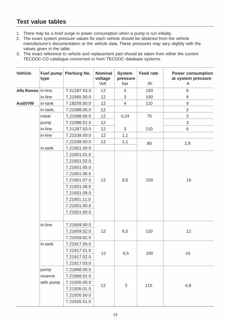
Test value tables
1. There may be a brief surge in power consumption when a pump is run initially.2. The exact system pressure values for each vehicle should be obtained from the vehicle
manufacturer’s documentation or the vehicle data. These pressures may vary slightly with thevalues given in the table.
3. The exact reference to vehicle and replacement part should be taken from either the currentTECDOC-CD catalogue concerned or from TECDOC database systems.
80 2,8
12 6,5 100 16
12 3 115 4,8
15
4 5 18
1 2 3
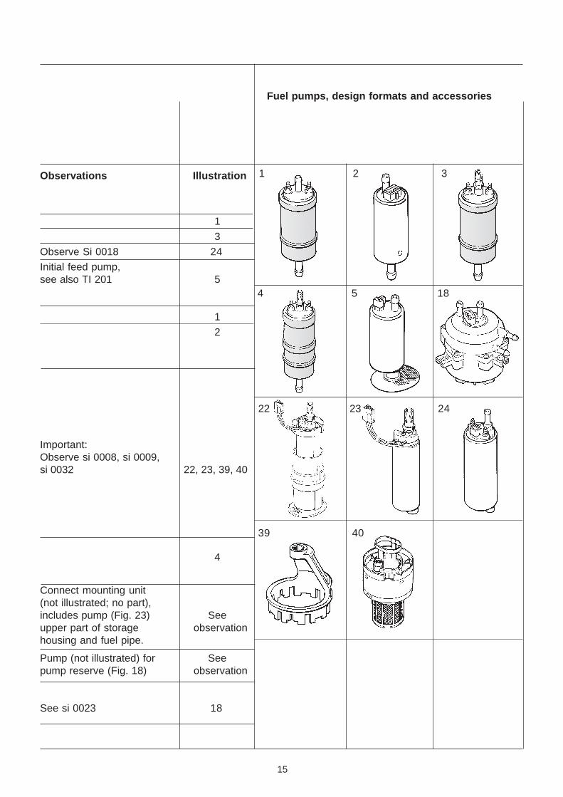
Fuel pumps, design formats and accessories
Observations Illustration
1
3
Observe Si 0018 24
Initial feed pump,see also TI 201 5
1
2
Important:Observe si 0008, si 0009,si 0032 22, 23, 39, 40
4
Connect mounting unit(not illustrated; no part),includes pump (Fig. 23) Seeupper part of storage observationhousing and fuel pipe.
Pump (not illustrated) for Seepump reserve (Fig. 18) observation
See si 0023 18
39 40
22 23 24
16
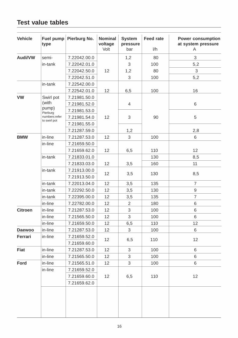
Test value tables
Vehicle Fuel pump Pierburg No. Nominal System Feed rate Power consumptiontype voltage pressure at system pressure
Volt bar l/h A
Audi/VW semi- 7.22042.00.0 1,2 80 3
in-tank 7.22042.01.0 3 100 5,2
7.22042.50.0 12 1,2 80 3
7.22042.51.0 3 100 5,2
in-tank 7.22542.00.0
7.22542.01.0 12 6,5 100 16
VW 7.21981.50.0
7.21981.52.0 4 6
7.21981.53.0
7.21981.54.0 12 3 90 5
7.21981.55.0
7.21287.59.0 1,2 2,8
BMW in-line 7.21287.53.0 12 3 100 6
in-line 7.21659.50.0
7.21659.62.0 12 6,5 110 12
in-tank 7.21833.01.0 130 8,5
7.21833.03.0 12 3,5 160 11
in-tank 7.21913.00.0
7.21913.50.0
in-tank 7.22013.04.0 12 3,5 135 7
in-tank 7.22292.50.0 12 3,5 130 9
in-tank 7.22395.00.0 12 3,5 135 7
in-line 7.22782.00.0 12 2 180 6
Citroen in-line 7.21287.53.0 12 3 100 6
in-line 7.21565.50.0 12 3 100 6
in-line 7.21659.50.0 12 6,5 110 12
Daewoo in-line 7.21287.53.0 12 3 100 6
Ferrari in-line 7.21659.52.0
7.21659.60.0
Fiat in-line 7.21287.53.0 12 3 100 6
in-line 7.21565.50.0 12 3 100 6
Ford in-line 7.21565.51.0 12 3 100 6
in-line 7.21659.52.0
7.21659.60.0 12 6,5 110 12
7.21659.62.0
Swirl pot(withpump)Pierburgnumbers referto swirl pot
12 6,5 110 12
12 3,5 130 8,5
17
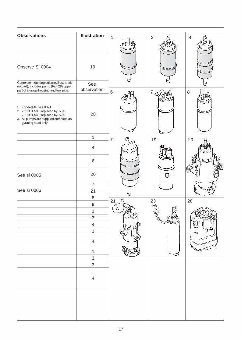
Observations Illustration
Observe Si 0004 19
1 3 4
Complete mounting unit (not illustrated;no part), includes pump (Fig. 28) upperpart of storage housing and fuel pipe.
1. For details, see 00212. 7.21981.53.0 replaced by .50.0
7.21981.54.0 replaced by .52.03. All pumps are supplied complete as
gyrating head only
Seeobservation
21 23 28
9 19 20
6 7 8
See si 0005
See si 0006
1
4
6
20
7
21
8
9
1
3
4
1
4
1
3
3
4
28
18
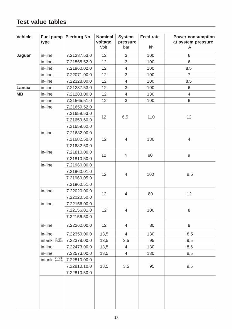
Test value tables
Vehicle Fuel pump Pierburg No. Nominal System Feed rate Power consumptiontype voltage pressure at system pressure
Volt bar l/h A
Jaguar in-line 7.21287.53.0 12 3 100 6
in-line 7.21565.52.0 12 3 100 6
in-line 7.21960.02.0 12 4 100 8,5
in-line 7.22071.00.0 12 3 100 7
in-line 7.22328.00.0 12 4 100 8,5
Lancia in-line 7.21287.53.0 12 3 100 6
MB in-line 7.21283.00.0 12 4 130 4
in-line 7.21565.51.0 12 3 100 6
in-line 7.21659.52.0
7.21659.53.0
7.21659.60.0
7.21659.62.0
in-line 7.21682.00.0
7.21682.50.0 12 4 130 4
7.21682.60.0
in-line 7.21810.00.0
7.21810.50.0
in-line 7.21960.00.0
7.21960.01.0
7.21960.05.0
7.21960.51.0
in-line 7.22020.00.0
7.22020.50.0
in-line 7.22156.00.0
7.22156.01.0 12 4 100 8
7.22156.50.0
in-line 7.22262.00.0 12 4 80 9
in-line 7.22359.00.0 13,5 4 130 8,5
intank 7.22378.00.0 13,5 3,5 95 9,5
in-line 7.22473.00.0 13,5 4 130 8,5
in-line 7.22573.00.0 13,5 4 130 8,5
intank 7.22810.00.0
7.22810.10.0 13,5 3,5 95 9,5
7.22810.50.0
12 6,5 110 12
12 4 80 9
12 4 100 8,5
12 4 80 12
in-tank-module
in-tank-module
19
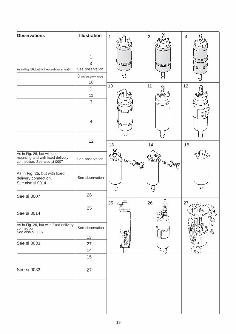
Observations Illustration 1 3 4
See observation
1
3
3 (without screw neck)
See observation
10 11 12
25 26 27
13 14 15
See observationAs in Fig. 10, but without rubber sheath
10
1
11
3
4
12
As in Fig. 26, but withoutmounting and with fixed deliveryconnection. See also si 0007
As in Fig. 25, but with fixeddelivery connection.See also si 0014
See si 0007 26
25See si 0014
See observation
13
27
14
15
27
See si 0033
As in Fig. 26, but with fixed deliveryconnection.See also si 0007
See si 0033
20
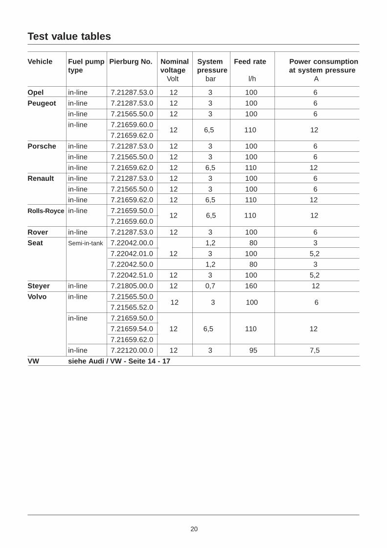
Test value tables
Vehicle Fuel pump Pierburg No. Nominal System Feed rate Power consumptiontype voltage pressure at system pressure
Volt bar l/h A
Opel in-line 7.21287.53.0 12 3 100 6
Peugeot in-line 7.21287.53.0 12 3 100 6
in-line 7.21565.50.0 12 3 100 6
in-line 7.21659.60.0
7.21659.62.0
Porsche in-line 7.21287.53.0 12 3 100 6
in-line 7.21565.50.0 12 3 100 6
in-line 7.21659.62.0 12 6,5 110 12
Renault in-line 7.21287.53.0 12 3 100 6
in-line 7.21565.50.0 12 3 100 6
in-line 7.21659.62.0 12 6,5 110 12
Rolls-Royce in-line 7.21659.50.0
7.21659.60.0
Rover in-line 7.21287.53.0 12 3 100 6
Seat Semi-in-tank 7.22042.00.0 1,2 80 3
7.22042.01.0 12 3 100 5,2
7.22042.50.0 1,2 80 3
7.22042.51.0 12 3 100 5,2
Steyer in-line 7.21805.00.0 12 0,7 160 12
Volvo in-line 7.21565.50.0
7.21565.52.0
in-line 7.21659.50.0
7.21659.54.0 12 6,5 110 12
7.21659.62.0
in-line 7.22120.00.0 12 3 95 7,5
VW siehe Audi / VW - Seite 14 - 17
12 3 100 6
12 6,5 110 12
12 6,5 110 12
21
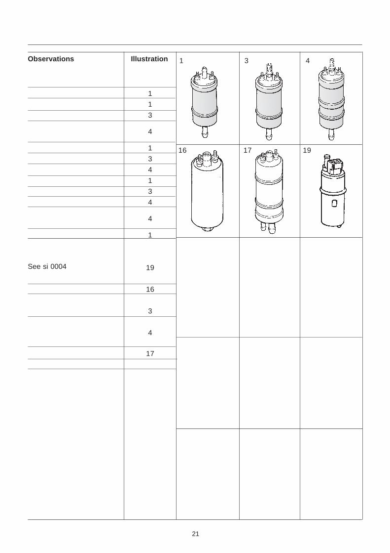
1 3 4Observations Illustration
1
1
3
4
1
3
4
1
3
4
4
1
19
16
3
4
17
16 17 19
See si 0004
22
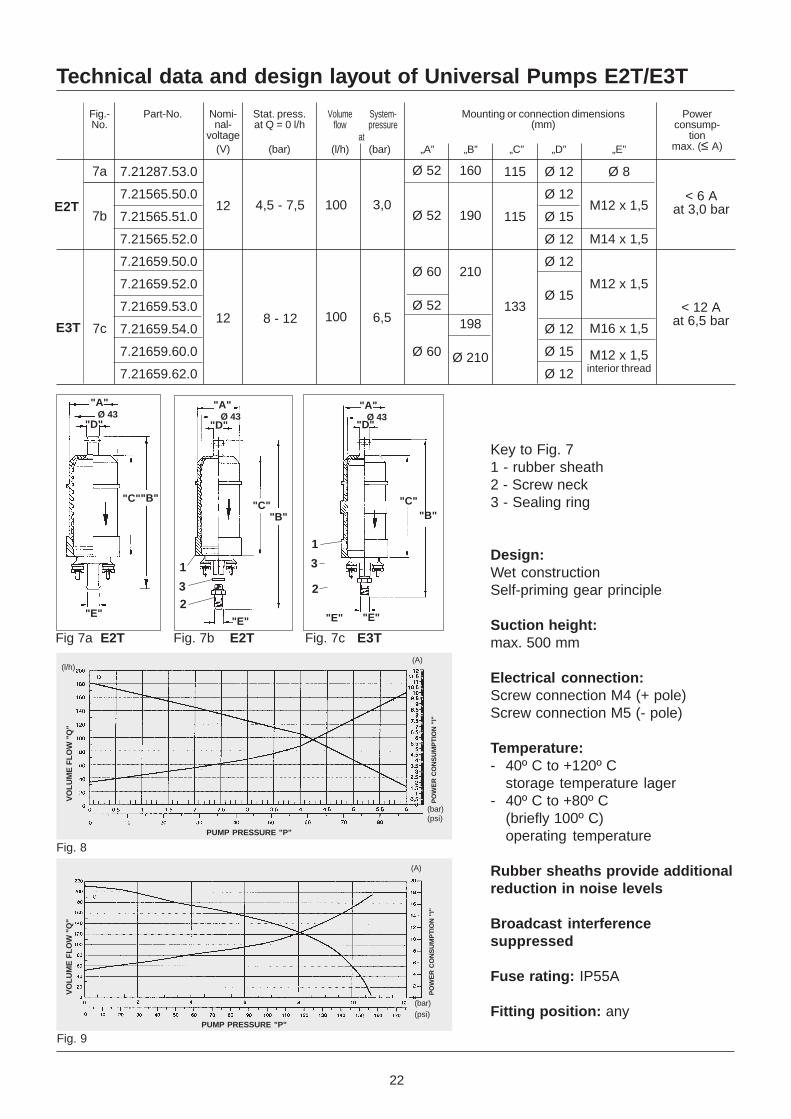
Technical data and design layout of Universal Pumps E2T/E3T
12
12
4,5 - 7,5
7.21287.53.0
7.21565.50.0
7.21565.51.0
7.21565.52.0
7.21659.50.0
7.21659.52.0
7.21659.53.0
7.21659.54.0
7.21659.60.0
7.21659.62.0
100
100
3,0
6,58 - 12
Part-No. Nomi-nal-
voltage(V)
Stat. press.at Q = 0 l/h
(bar)
Mounting or connection dimensions(mm)
„E”
Fig.-No.
7a
7b
7c
at(bar)
Volumeflow
System-pressure
(l/h) „A” „B” „C” „D”
160
190
210
198
Ø 210
115
115
133
Ø 12
Ø 12
Ø 15
Ø 12
Ø 12
Ø 15
Ø 12
Ø 15
Ø 12
Ø 8
M12 x 1,5
M14 x 1,5
M12 x 1,5
M16 x 1,5
M12 x 1,5
Ø 52
Ø 52
Ø 60
Ø 52
Ø 60
E2T
Powerconsump-
tionmax. (≤ A)
< 6 Aat 3,0 bar
< 12 Aat 6,5 bar
Key to Fig. 71 - rubber sheath2 - Screw neck3 - Sealing ring
Design:Wet constructionSelf-priming gear principle
Suction height:max. 500 mm
Electrical connection:Screw connection M4 (+ pole)Screw connection M5 (- pole)
Temperature:- 40º C to +120º C
storage temperature lager- 40º C to +80º C
(briefly 100º C)operating temperature
Rubber sheaths provide additionalreduction in noise levels
Broadcast interferencesuppressed
Fuse rating: IP55A
Fitting position: anyElectrical
"E"
"C""B"
"A"
"D"Ø 43
"A"Ø 43
"D"
"A"
"D"Ø 43
"C""B"
"C""B"
"E"
1
32
1
3
"E""E"
2
VO
LU
ME
FL
OW
"Q
"
PO
WE
R C
ON
SU
MP
TIO
N "
I"
(A)
(bar)(psi)
PUMP PRESSURE "P"
VO
LU
ME
FL
OW
"Q
"
(l/h)(A)
PO
WE
R C
ON
SU
MP
TIO
N "
I"
(bar)(psi)
PUMP PRESSURE "P"
Fig. 8
Fig. 9
Fig 7a E2T Fig. 7b E2T Fig. 7c E3T
E3T
interior thread
23
Fuel system designs
Brief description
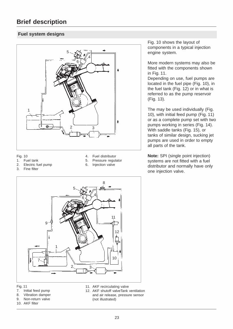
Fig. 10 shows the layout ofcomponents in a typical injectionengine system.
More modern systems may also befitted with the components shownin Fig. 11.Depending on use, fuel pumps arelocated in the fuel pipe (Fig. 10), inthe fuel tank (Fig. 12) or in what isreferred to as the pump reservoir(Fig. 13).
The may be used individually (Fig.10), with initial feed pump (Fig. 11)or as a complete pump set with twopumps working in series (Fig. 14).With saddle tanks (Fig. 15), ortanks of similar design, sucking jetpumps are used in order to emptyall parts of the tank.
Note: SPI (single point injection)systems are not fitted with a fueldistributor and normally have onlyone injection valve.
Fig. 117. Initial feed pump8. Vibration damper9. Non-return valve10. AKF filter
1
32
45
6
Fig. 101. Fuel tank2. Electric fuel pump3. Fine filter
4. Fuel distributor5. Pressure regulator6. Injection valve
11. AKF recirculating valve12. AKF shutoff valveTank ventilation
and air release, pressure sensor(not illustrated)
5
64
8
9
7
1
2 3
10
12
11
24
Fuel system designs
Brief description
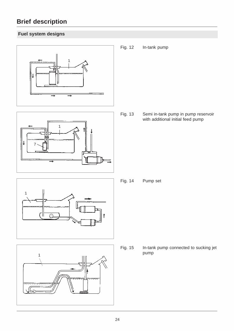
Fig. 12 In-tank pump
Fig. 13 Semi in-tank pump in pump reservoirwith additional initial feed pump
Fig. 14 Pump set
Fig. 15 In-tank pump connected to sucking jetpump1
1
1
7
1
25
Function
Brief description
A pressure regulator fitted tothe system controls pressureand maintains a constantdifference between fuel press-ure and inlet pipe pressure. Thisensures that the injectionquantity is determined solely bythe time the injection valveremains open. The regulator islocated in the fuel distributoroutlet, and is partly integrated inthe distributor.
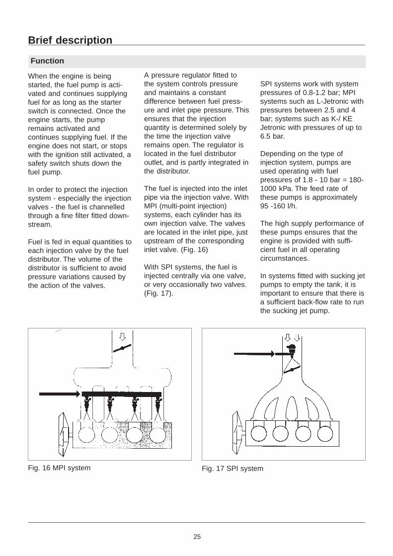
The fuel is injected into the inletpipe via the injection valve. WithMPI (multi-point injection)systems, each cylinder has itsown injection valve. The valvesare located in the inlet pipe, justupstream of the correspondinginlet valve. (Fig. 16)
With SPI systems, the fuel isinjected centrally via one valve,or very occasionally two valves.(Fig. 17).
SPI systems work with systempressures of 0.8-1.2 bar; MPIsystems such as L-Jetronic withpressures between 2.5 and 4bar; systems such as K-/ KEJetronic with pressures of up to6.5 bar.
Depending on the type ofinjection system, pumps areused operating with fuelpressures of 1.8 - 10 bar = 180-1000 kPa. The feed rate ofthese pumps is approximately95 -160 l/h.
The high supply performance ofthese pumps ensures that theengine is provided with suffi-cient fuel in all operatingcircumstances.
In systems fitted with sucking jetpumps to empty the tank, it isimportant to ensure that there isa sufficient back-flow rate to runthe sucking jet pump.
When the engine is beingstarted, the fuel pump is acti-vated and continues supplyingfuel for as long as the starterswitch is connected. Once theengine starts, the pumpremains activated andcontinues supplying fuel. If theengine does not start, or stopswith the ignition still activated, asafety switch shuts down thefuel pump.
In order to protect the injectionsystem - especially the injectionvalves - the fuel is channelledthrough a fine filter fitted down-stream.
Fuel is fed in equal quantities toeach injection valve by the fueldistributor. The volume of thedistributor is sufficient to avoidpressure variations caused bythe action of the valves.
Fig. 16 MPI system Fig. 17 SPI system
26
Fuel pumps
System Components
Only electrically operated fuelpumps are used with injectionmotors. Depending on the typeof use, different pump
mechanisms are used, eithersingly or in combination, alongwith motors of variouscapacities.
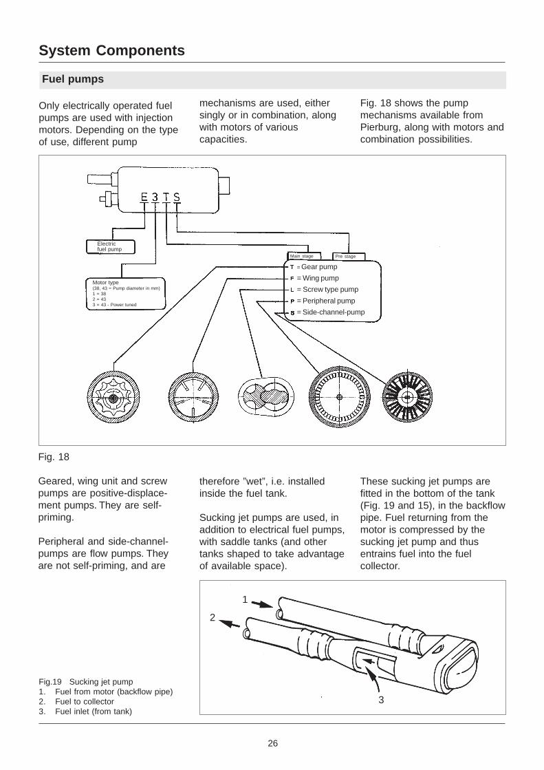
Fig. 18 shows the pumpmechanisms available fromPierburg, along with motors andcombination possibilities.
These sucking jet pumps arefitted in the bottom of the tank(Fig. 19 and 15), in the backflowpipe. Fuel returning from themotor is compressed by thesucking jet pump and thusentrains fuel into the fuelcollector.
therefore ”wet”, i.e. installedinside the fuel tank.
Sucking jet pumps are used, inaddition to electrical fuel pumps,with saddle tanks (and othertanks shaped to take advantageof available space).
Fig. 18
Geared, wing unit and screwpumps are positive-displace-ment pumps. They are self-priming.
Peripheral and side-channel-pumps are flow pumps. Theyare not self-priming, and are
Fig.19 Sucking jet pump1. Fuel from motor (backflow pipe)2. Fuel to collector3. Fuel inlet (from tank)
1
2
3
Electricfuel pump
= Gear pump
= Wing pump
= Screw type pump
= Peripheral pump
= Side-channel-pump
Motor type(38, 43 = Pump diameter in mm)1 = 382 = 433 = 43 - Power tuned
Main stage Pre stage
27
Pressure regulator
System components
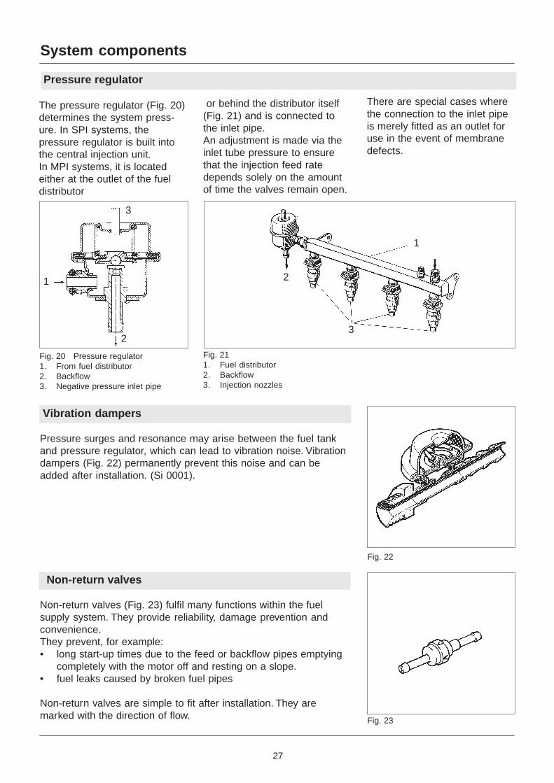
The pressure regulator (Fig. 20)determines the system press-ure. In SPI systems, thepressure regulator is built intothe central injection unit.In MPI systems, it is locatedeither at the outlet of the fueldistributor
or behind the distributor itself(Fig. 21) and is connected tothe inlet pipe.An adjustment is made via theinlet tube pressure to ensurethat the injection feed ratedepends solely on the amountof time the valves remain open.
There are special cases wherethe connection to the inlet pipeis merely fitted as an outlet foruse in the event of membranedefects.
Vibration dampers
Pressure surges and resonance may arise between the fuel tankand pressure regulator, which can lead to vibration noise. Vibrationdampers (Fig. 22) permanently prevent this noise and can beadded after installation. (Si 0001).
Non-return valves
Non-return valves (Fig. 23) fulfil many functions within the fuelsupply system. They provide reliability, damage prevention andconvenience.They prevent, for example:• long start-up times due to the feed or backflow pipes emptying
completely with the motor off and resting on a slope.• fuel leaks caused by broken fuel pipes
Non-return valves are simple to fit after installation. They aremarked with the direction of flow.
Fig. 20 Pressure regulator1. From fuel distributor2. Backflow3. Negative pressure inlet pipe
Fig. 211. Fuel distributor2. Backflow3. Injection nozzles
Fig. 22
1
2
3
2
3
1
Fig. 23
28
AKF systems
System Components
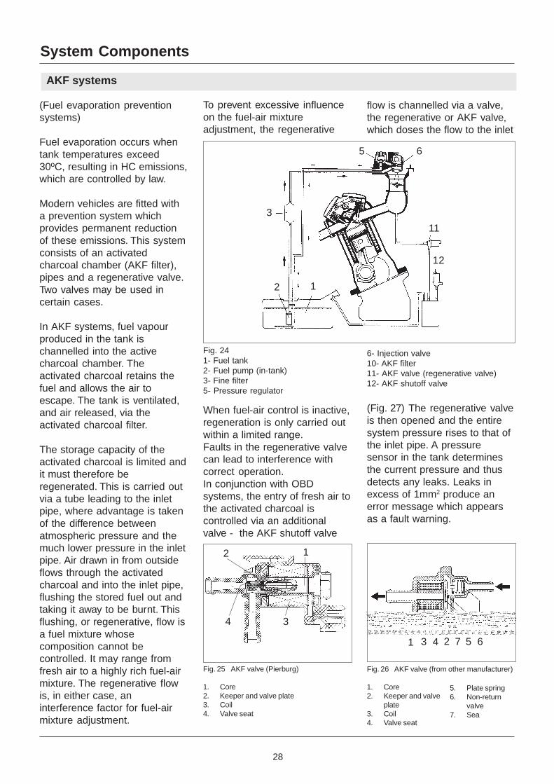
To prevent excessive influenceon the fuel-air mixtureadjustment, the regenerative
flow is channelled via a valve,the regenerative or AKF valve,which doses the flow to the inlet
(Fuel evaporation preventionsystems)
Fuel evaporation occurs whentank temperatures exceed30ºC, resulting in HC emissions,which are controlled by law.
Modern vehicles are fitted witha prevention system whichprovides permanent reductionof these emissions. This systemconsists of an activatedcharcoal chamber (AKF filter),pipes and a regenerative valve.Two valves may be used incertain cases.
In AKF systems, fuel vapourproduced in the tank ischannelled into the activecharcoal chamber. Theactivated charcoal retains thefuel and allows the air toescape. The tank is ventilated,and air released, via theactivated charcoal filter.
The storage capacity of theactivated charcoal is limited andit must therefore beregenerated. This is carried outvia a tube leading to the inletpipe, where advantage is takenof the difference betweenatmospheric pressure and themuch lower pressure in the inletpipe. Air drawn in from outsideflows through the activatedcharcoal and into the inlet pipe,flushing the stored fuel out andtaking it away to be burnt. Thisflushing, or regenerative, flow isa fuel mixture whosecomposition cannot becontrolled. It may range fromfresh air to a highly rich fuel-airmixture. The regenerative flowis, in either case, aninterference factor for fuel-airmixture adjustment.
Fig. 25 AKF valve (Pierburg)
1. Core2. Keeper and valve plate3. Coil4. Valve seat
Fig. 26 AKF valve (from other manufacturer)
1. Core2. Keeper and valve
plate3. Coil4. Valve seat
5. Plate spring6. Non-return
valve7. Sea
When fuel-air control is inactive,regeneration is only carried outwithin a limited range.Faults in the regenerative valvecan lead to interference withcorrect operation.In conjunction with OBDsystems, the entry of fresh air tothe activated charcoal iscontrolled via an additionalvalve - the AKF shutoff valve
(Fig. 27) The regenerative valveis then opened and the entiresystem pressure rises to that ofthe inlet pipe. A pressuresensor in the tank determinesthe current pressure and thusdetects any leaks. Leaks inexcess of 1mm2 produce anerror message which appearsas a fault warning.
Fig. 241- Fuel tank2- Fuel pump (in-tank)3- Fine filter5- Pressure regulator
6- Injection valve10- AKF filter11- AKF valve (regenerative valve)12- AKF shutoff valve
12
3
5 6
11
12
12
4 3
1 3 4 2 7 5 6
29
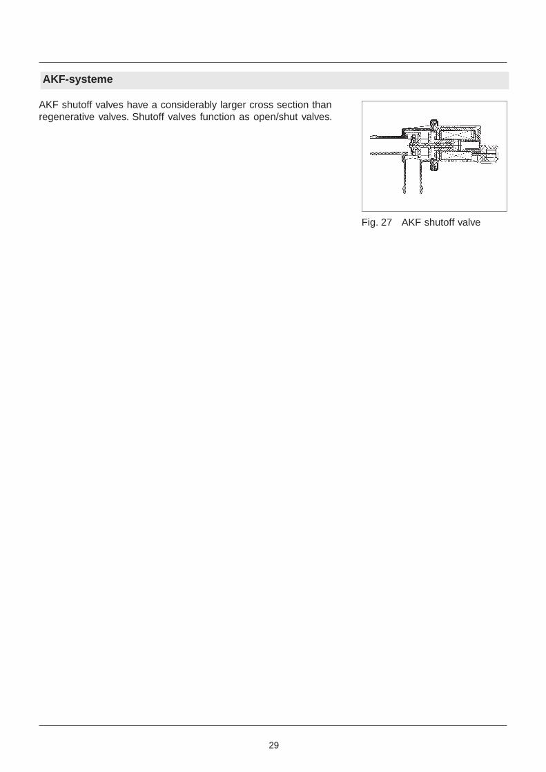
AKF-systeme
AKF shutoff valves have a considerably larger cross section thanregenerative valves. Shutoff valves function as open/shut valves.
Fig. 27 AKF shutoff valve
30
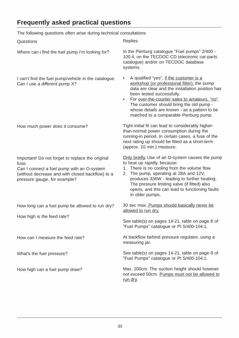
Frequently asked practical questions
The following questions often arise during technical consultations
Questions
Where can i find the fuel pump I’m looking for?
I can’t find the fuel pump/vehicle in the catalogue.Can I use a different pump X?
How much power does it consume?
Important! Do not forget to replace the originalfuse.Can I connect a fuel pump with an O-system(without decrease and with closed backflow) to apressure gauge, for example?
How long can a fuel pump be allowed to run dry?
How high is the feed rate?
How can I measure the feed rate?
What’s the fuel pressure?
How high can a fuel pump draw?
Replies
In the Pierburg catalogue ”Fuel pumps” 2/400 -100.4, on the TECDOC CD (electronic car-partscatalogue) and/or on TECDOC databasesystems.
• A qualified ”yes”, if the customer is aworkshop (or professional fitter), the pumpdata are clear and the installation position hasbeen tested successfully.
• For over-the-counter sales to amateurs, ”no”.The customer should bring the old pump -whose details are known - as a pattern to bematched to a comparable Pierburg pump.
Tight initial fit can lead to considerably higher-than-normal power consumption during therunning-in period. In certain cases, a fuse of thenext rating up should be fitted as a short-term(approx. 10 min.) measure.
Only briefly. Use of an O-system causes the pumpto heat up rapidly, because:1. There is no cooling from the volume flow.2. The pump, operating at 28A and 12V,
produces 336W - leading to further heating.The pressure limiting valve (if fitted) alsoopens, and this can lead to functioning faultsin older pumps.
30 sec max. Pumps should basically never beallowed to run dry.
See table(s) on pages 14-21, table on page 8 of”Fuel Pumps” catalogue or PI 5/400-104.1.
At backflow behind pressure regulator, using ameasuring jar.
See table(s) on pages 14-21, table on page 8 of”Fuel Pumps” catalogue or PI 5/400-104.1.
Max. 200cm. The suction height should howevernot exceed 50cm. Pumps must not be allowed torun dry.

31
Overview of further information literature
The following material is available for information on the subject of ”fuel supply”.
Title Reg. No.
• ”Fuel Pumps” catalogue 2/4 00-100.4
• ”pi” product information
- Electrical fuel pumps 5/4 00-104.1
- Fuel pressure testing device - pi 0005(Replaces pi 5/20 00-503.2) 5/20 00 - 503.4
- Extension pieces to pressure testing device 4.07360.50.0 5/20 00-503.3• Operating instructions for pressure testing device 3.45222.130
• Servicing Tips and Information”Engine fuel injection supply systems” 6/4 00-100.1• ”si” servicing information
si 0001 Vibration dampers
si 0004 Electrical fuel pump for VW
si 0005 Electrical fuel pump for BMW - replacement
si 0006 Electrical fuel pump for BMW - replacement
si 0007 Electrical fuel pump for MB - new application
si 0008 Electrical fuel pump for Audi - new application
si 0009 Electrical fuel pump for Audi - replacement
si 0014 Electrical fuel pump for MB - new application
si 0015 Fuel pressure regulator various vehicles
si 0016 Safety shutoff for electrical fuel pumps
si 0018 Electrical fuel pump for Audi - replacement
si 0021 Replacement parts for fuel supply units
si 0028 Electrical fuel pump for MB - replacement
si 0031 Mechanical fuel pump for MB - replacement
si 0032 Electrical fuel pump for Audi - replacement New for ‘98
si 0033 Electrical fuel pump for MB - new application New for ’98
You can find further information on the following subjects:
• Fuel supply• Negative pressure supply• Air supply and• Reduction of pollutants
In the collected information ”Engine Components” Cat. No. 8.40000 82.2
These documents can be updated to 1998 with the 1998 annual supplement, Cat. No. 8.40000 85.8,obtainable for a nominal fee from Pierburg publications wholesalers.Pierburg Dealer
NEU
NEU
NEU
PIERBURG
Pierburg-Distributor
PIERBURG AGAlfred-Pierburg-Straße 1D- 41456 NeussGermany
(0 21 31) 5 20-0Fax (0 21 31) 5 20 663
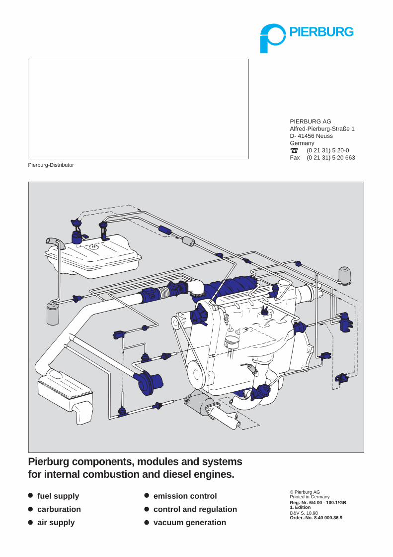
Pierburg components, modules and systemsfor internal combustion and diesel engines.
fuel supply
carburation
air supply
emission control
control and regulation
vacuum generation
© Pierburg AGPrinted in GermanyReg.-Nr. 6/4 00 - 100.1/GB1. EditionD&V S. 10.98Order.-No. 8.40 000.86.9
Recommended