SHIP & OFFSHOREBRAKING UNLIMITED
3rd edition
Made in Germany
PINTSCH BUBENZER GmbH
Friedrichshuettenstr. 1D-57548 Kirchen-WehbachPhone +49 27 41/94 88-0
Huenxer Str. 149D-46537 Dinslaken
Phone +49 20 64/602-0
www.pintschbubenzer.com
2018 P S H
www.pintschbubenzer.com
INT BUBEN ER
www.pintschbubenzer.com
Content
Hydraulic Disc Brakes B1 - B10
Electromagnetic Disc Brakes C1 - C19
Accessories CX1 - CX7
Brake Control Unit BCU2001 CX9 - CX11
Brake Control Unit BCMS-4 CX13 - CX15
B1
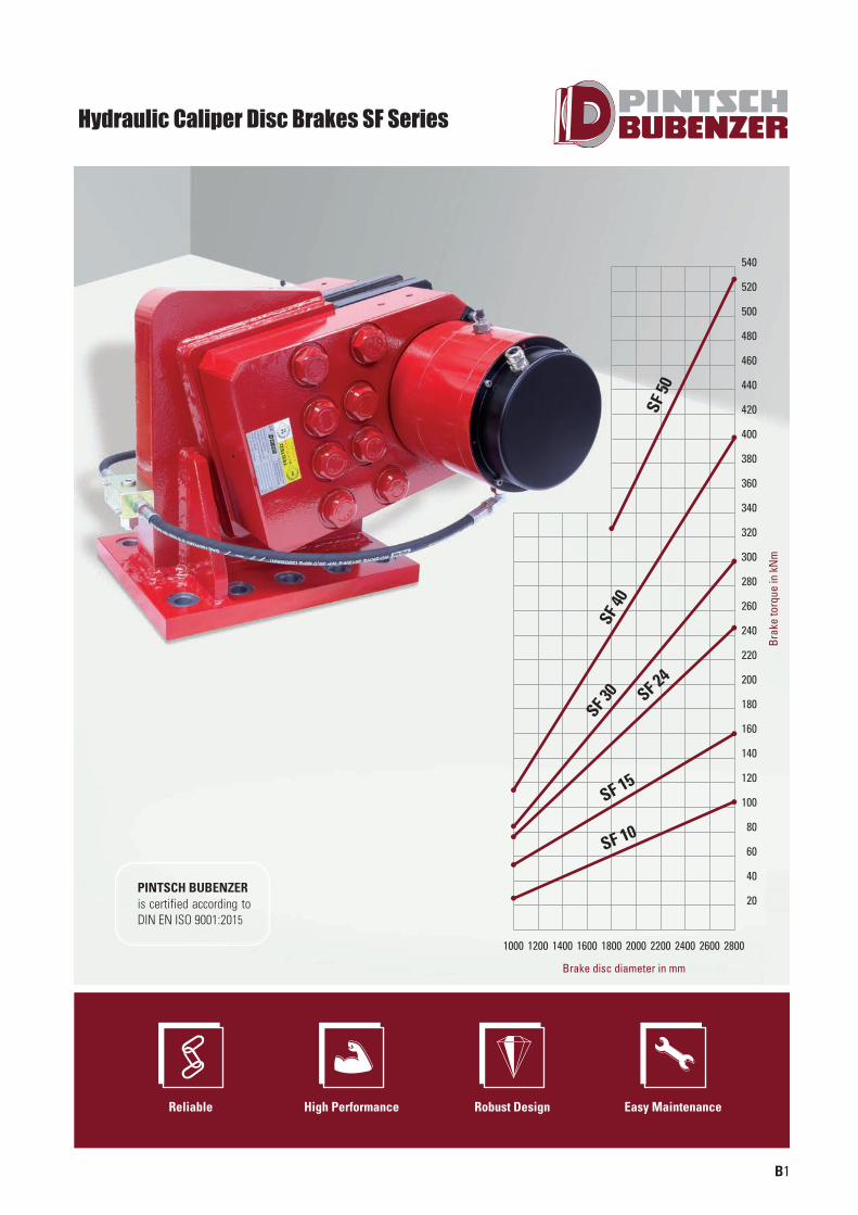
Hydraulic Caliper Disc Brakes SF Series
Reliable High Performance Robust Design Easy Maintenance
Brak
e to
rque
in k
Nm
Brake disc diameter in mm
PINTSCH BUBENZER is certified according to DIN EN ISO 9001:2015
1000 1200 1400 1600 1800 2000 2200 2400 2600 2800
540
520
500
480
460
440
420
400
380
360
340
320
300
280
260
240
220
200
180
160
140
120
100
80
60
40
20
SF 10
SF 40
SF 50
SF 24
SF 15
SF 30
SCHIFFBAU-UK-Innen-0814_pintsch bubenzer 21.08.14 15:03 Seite 3
B2
Description SF
Two identical caliper halves, ready for operation,with spring packs set to nominal force and limitswitch release control
Main Features
Limit switch wear control
Options
Sintered linings
Complete piped supports for one or more calipers
Hydraulic power unitsUp to 2 mm air gap between brake pad and disc
Special seals for flameproof fluids
Cleaning pads
Brake discs
Easy, manual pad wear compensation
Organic, non-asbestos linings
The high capacity of these brakes makes them particularly suitable as secondary emergency brakeson hoist gears and on downhill conveyor
Other applications are possible in material hand ling, requiring power and compact design ineither direction of rotation, particularly in replacingband brakes
Brakes for use in high duty cycle applications areto be specifically indicated prior to the technicalselection procedure
Applications
Brakes of this range are tested both mechanicallyand hydraulically and are set to nominal force. This setting can only be changed by the manu-facturer. Operating conditions other than describedin this brochure require the manufacturer´s approval and may influence the function of thecaliper and its components
Operating Restrictions
CMB contact force measurement
Please Note
We supply a detailed operating manual with every order. Nevertheless,we would point out that brakes are only as safe as the servicing andmaintenance performed while they are in operation. The guarantee forthe correct functioning of our brakes is only valid if the user adheres tothe German DIN standard 15434 part 2 (drum and disc brakes, servicingand maintenance in operation), or to comparable standards in his owncountry.
PINTSCH BUBENZER Service
This includes the verification of the brake selection, if required. A detailed questionnaire is provided for this purpose. Installation and commissioning on-site by PINTSCH BUBENZER service engineers is possible. Drawings as DWG/DXF files for your engineering department are available upon request.
SCHIFFBAU-UK-Innen-0814_pintsch bubenzer 21.08.14 15:03 Seite 4
B3
Rev. 12-06
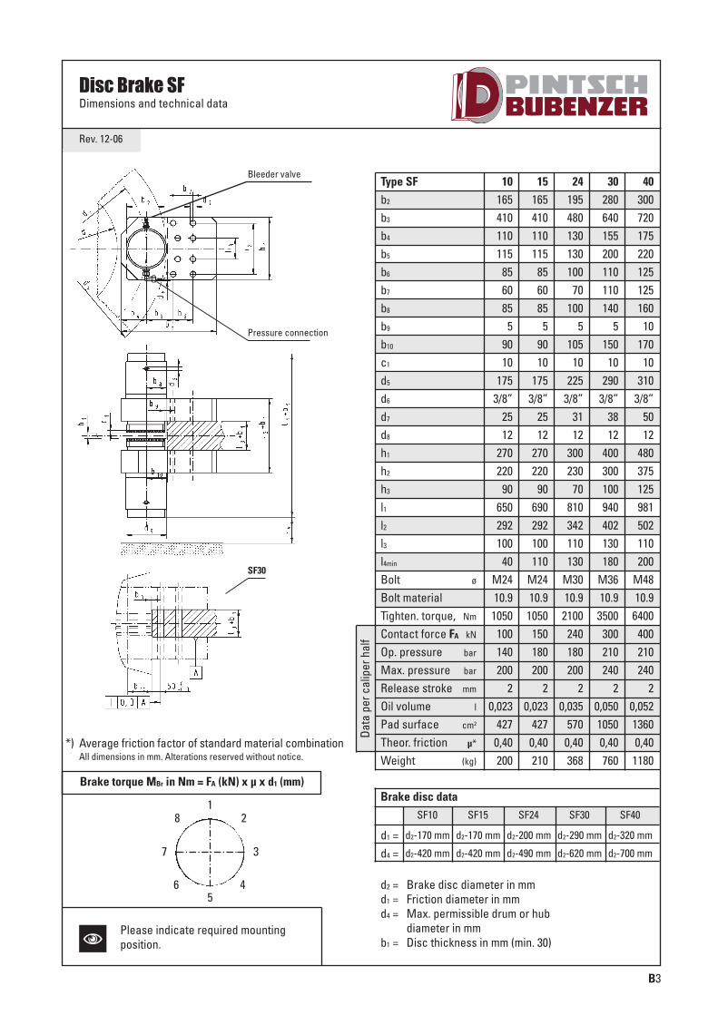
Disc Brake SFDimensions and technical data
Data
per
cal
iper
hal
f
Type SFb2
b3
b4
b5
b6
b7
b8
b9
b10
c1
d5
d6
d7
d8
h1
h2
h3
l1
l2
l3
l4min
Bolt ø
Bolt materialTighten. torque, Nm
Contact force FA kN
Op. pressure bar
Max. pressure bar
Release stroke mm
Oil volume l
Pad surface cm2
Theor. friction µ*
Weight (kg)
10165410110115
856085
59010
1753/8”
2512
270220
90650292100
40M2410.9
1050100140200
20,023
4270,40200
15165410110115
856085
59010
1753/8”
2512
270220
90690292100110
M2410.9
1050150180200
20,023
4270,40210
24195480130130100
70100
5105
10225
3/8”3112
300230
70810342110130
M3010.9
2100240180200
20,035
5700,40368
Brake disc data
d1 =
SF10 SF15 SF24 SF30 SF40
d2-170 mm d2-170 mm d2-200 mm d2-290 mm d2-320 mm
d4 = d2-420 mm d2-420 mm d2-490 mm d2-620 mm d2-700 mm
d2 = Brake disc diameter in mmd1 = Friction diameter in mmd4 = Max. permissible drum or hub
diameter in mmb1 = Disc thickness in mm (min. 30)
30280640155200110110140
5150
10290
3/8”3812
400300100940402130180
M3610.93500
300210240
20,05010500,40760
40300720175220125125160
10170
10310
3/8”5012
480375125981502110200
M4810.96400
400210240
20,05213600,401180
*) Average friction factor of standard material combinationAll dimensions in mm. Alterations reserved without notice.
Bleeder valve
Pressure connection
SF30
128
465
37
Brake torque MBr in Nm = FA (kN) x µ x d1 (mm)
NPlease indicate required mountingposition.
SCHIFFBAU-UK-Innen-0814_pintsch bubenzer 21.08.14 15:03 Seite 5

310
155
465
175 100130
440
610
d2 (min. 1800mm)
d4 = d2-490d1 = d2-206
d2/2-117
CL
55 55
ca. 813 + b1
225
225
A
A
10
b1
140
390
min
. 130
min
. 130
ca. 1
073
+ b1
65 100
155
±0,3
310
±0,0
2
465
±0,3
195
300
300
10
38
60 F7
M24
A-A
Rev. 02-14
Contact force FA kN 510
Operating pressure p bar 180
Type SF 50
Max. pressure pmax. bar 200
Release stroke mm 2
Oil volume l 0,07
Pad surface cm2 1100
Theor. friction factor μ* 0,40
Weight (without bracket) kg
d2 = Brake disc diameter in mmd1 = Friction diameter in mmd4 = Max. permissible drum or
hub diameter in mmb1 = Brake disc thickness in mm (min. 30)
ca. 730
Data
per
cal
iper
hal
f
All dimensions in mmAlterations reserved without notice
*) Theor. friction factor of standard materialcombination
Brake Torque MBr in Nm = FA (kN) x µ x d1 (mm)
Disc Brake SF 50Dimensions and technical data
4 x hexagon bolt according toDIN 931 or DIN EN ISO 4017 - M36-10.9tightening torque = 3550 Nm (μ = 0,12)
2 x hexagon socket head screwaccording to DIN 912 - M24-8.8
tightening torque = 675 Nm (μ = 0,12)
Pressure port
Bleedervalve
BX3
SCHIFFBAU-UK-Innen-0814_pintsch bubenzer 21.08.14 15:03 Seite 6
B4
Rev. 12-06
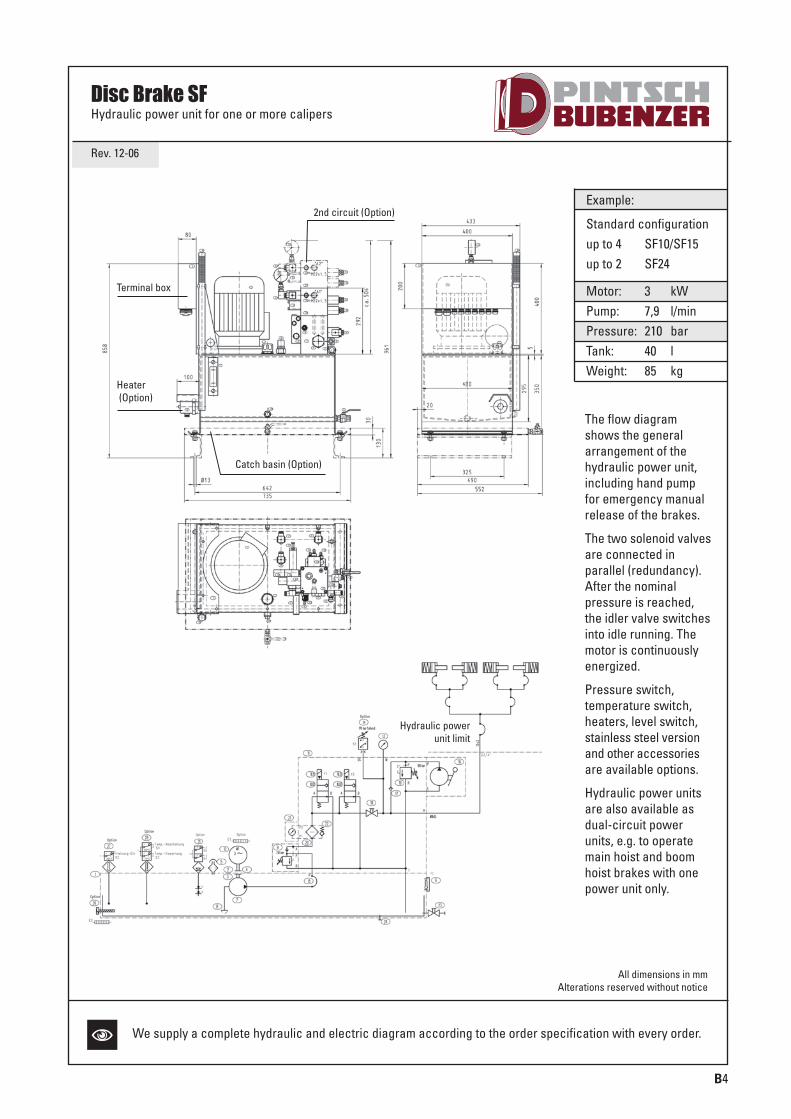
Disc Brake SFHydraulic power unit for one or more calipers
Hydraulic powerunit limit
Catch basin (Option)
2nd circuit (Option)
Heater(Option)
Terminal box
Example:
Standard configurationup to 4 SF10/SF15up to 2 SF24
Motor: 3 kWPump: 7,9 l/minPressure: 210 barTank: 40 lWeight: 85 kg
The flow diagramshows the generalarrangement of the hydraulic power unit,including hand pumpfor emergency manualrelease of the brakes.
The two solenoid valvesare connected in parallel (redundancy).After the nominal pressure is reached,the idler valve switchesinto idle running. Themotor is continuouslyenergized.
Pressure switch, temperature switch,heaters, level switch,stainless steel versionand other accessoriesare available options.
Hydraulic power unitsare also available asdual-circuit powerunits, e.g. to operatemain hoist and boomhoist brakes with onepower unit only.
All dimensions in mmAlterations reserved without notice
N We supply a complete hydraulic and electric diagram according to the order specification with every order.
SCHIFFBAU-UK-Innen-0814_pintsch bubenzer 21.08.14 15:03 Seite 7
B5
Rev. 09-02
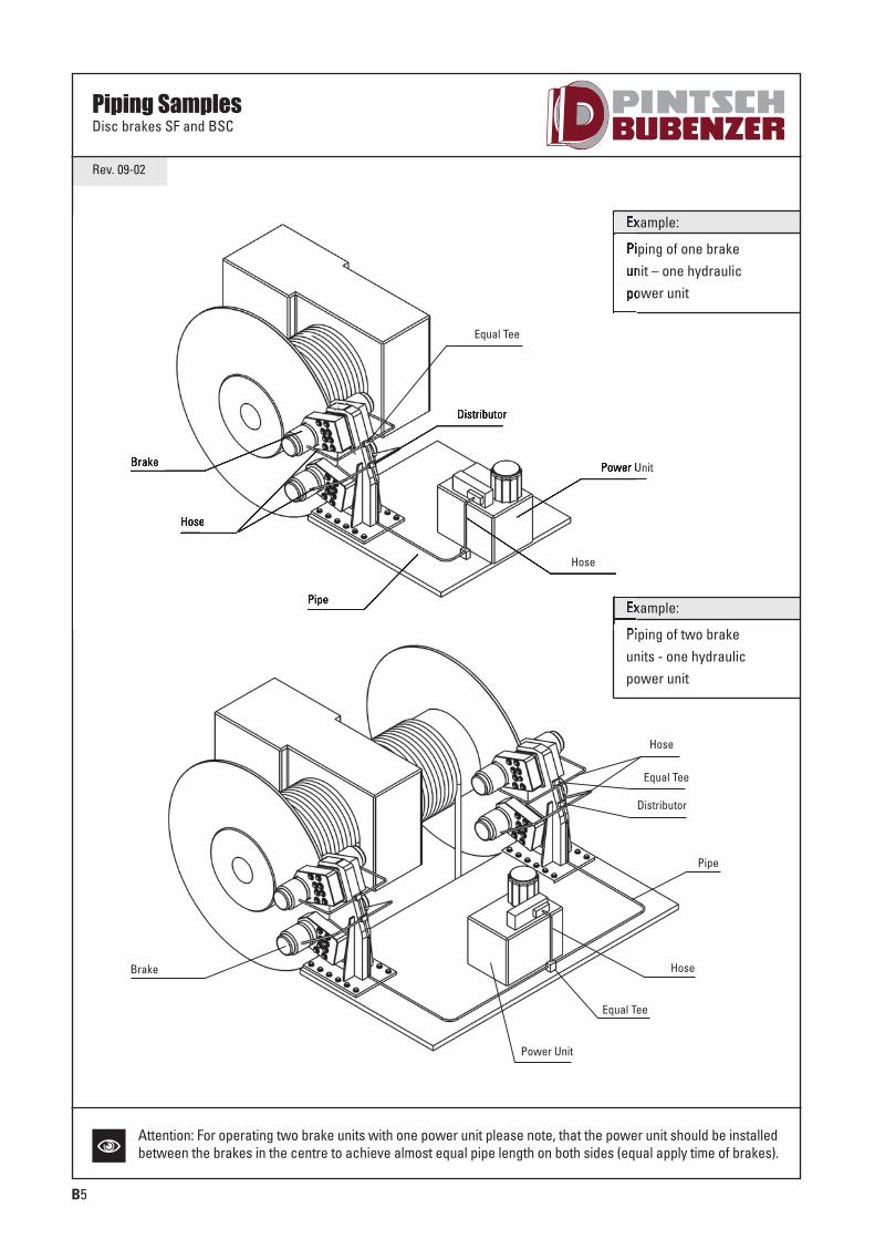
Piping SamplesDisc brakes SF and BSC
Example:
Piping of one brakeunit – one hydraulicpower unit
Example:
Piping of two brakeunits - one hydraulicpower unit
Power Unit
Power Unit
Equal Tee
Equal Tee
Distributor
Distributor
Pipe
Pipe
Hose
Hose
Hose
Brake
Brake
Equal Tee
Hose
NAttention: For operating two brake units with one power unit please note, that the power unit should be installedbetween the brakes in the centre to achieve almost equal pipe length on both sides (equal apply time of brakes).
SCHIFFBAU-UK-Innen-0814_pintsch bubenzer 21.08.14 15:03 Seite 8
BX6
Rev. 11-04
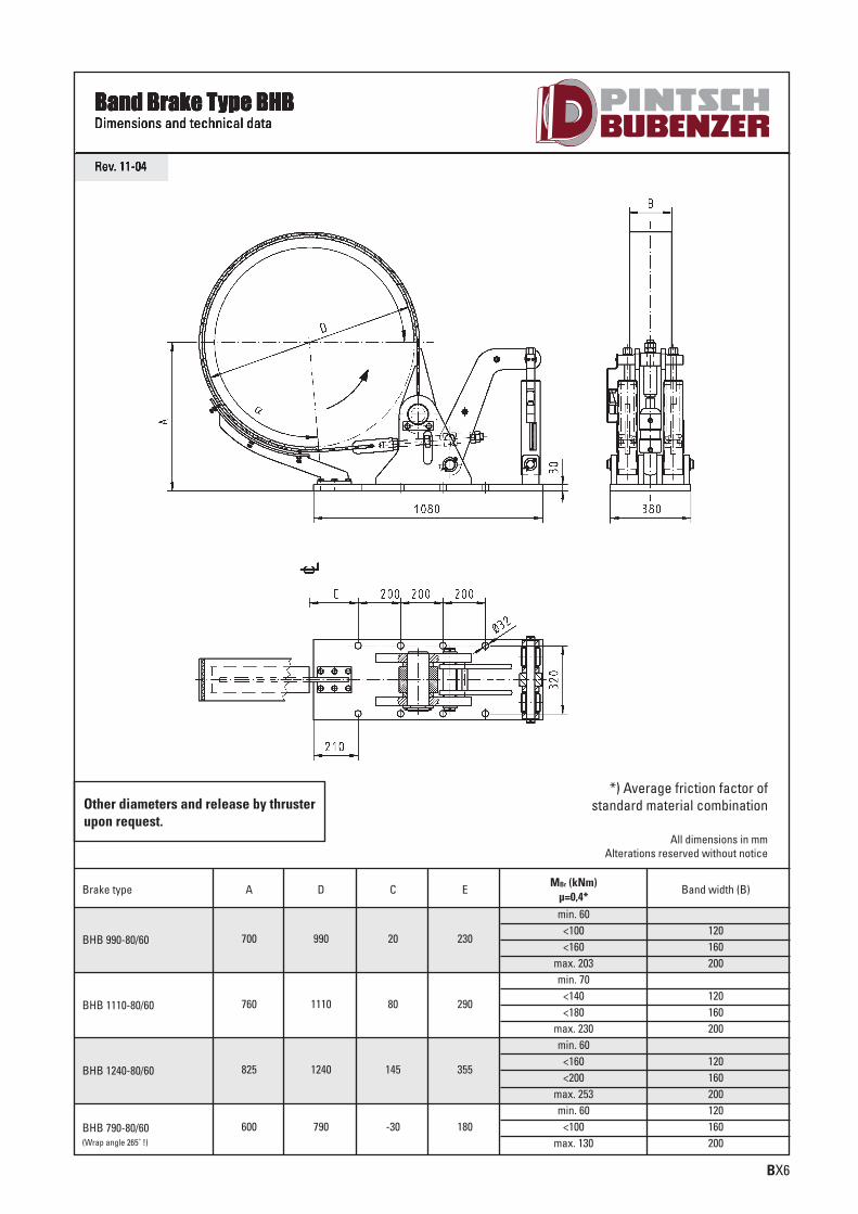
Band Brake Type BHBDimensions and technical data
Brake type A D C EMBr (kNm)
µ=0,4*
700 990 20 230
min. 60<100<160
max. 203
Band width (B)
120160200
BHB 990-80/60
760 1110 80 290
min. 70<140<180
max. 230
120160200
BHB 1110-80/60
825 1240 145 355
min. 60<160<200
max. 253
120160200
BHB 1240-80/60
600 790 -30 180min. 60
<100max. 130
120160200
BHB 790-80/60(Wrap angle 265˚ !)
*) Average friction factor ofstandard material combination
All dimensions in mmAlterations reserved without notice
Other diameters and release by thrusterupon request.
SCHIFFBAU-UK-Innen-0814_pintsch bubenzer 21.08.14 15:03 Seite 9

Notes
SCHIFFBAU-UK-Innen-0814_pintsch bubenzer 21.08.14 15:03 Seite 10
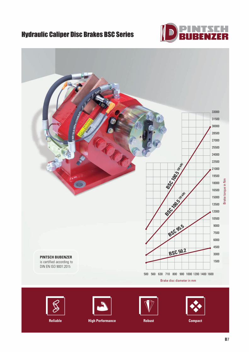
500 560 630 710 800 900 1000 1200 1400 1600
33000
31500
30000
28500
27000
25500
24000
22500
21000
19500
18000
16500
15000
13500
12000
10500
9000
7500
6000
4500
3000
1500
BSC
100.5
(50 k
N)
BSC 100.5
(35 k
N)
BSC 95.5
BSC 50.2
B7
Hydraulic Caliper Disc Brakes BSC Series
Reliable High Performance Robust Compact
Brak
e to
rque
in N
m
Brake disc diameter in mm
PINTSCH BUBENZER is certified according to DIN EN ISO 9001:2015
SCHIFFBAU-UK-Innen-0814_pintsch bubenzer 21.08.14 15:03 Seite 11
B8
Description BSC
Two identical caliper halves, ready for operation,with spring packs set to nominal force
Main Features
Limit switch release control
Options
Limit switch wear control
Sintered linings
Complete piped supports for one or more calipers
Up to 1 mm air gap between brake pad and disc
Hydraulic power units
Special seals for flameproof fluids
Cleaning pads
Brake discs
Easy, manual pad wear compensation
Organic, non-asbestos linings
The high capacity of these brakes makes them particularly suitable as service- or secondary emergency brakes e.g. on hoists, slewing drivesand belt conveyors
Other applications are in material hand ling, mechanical engineering and wind turbine industry, where high holding forces are required independent of the direction of rotation withinlimited space
Applications
Brakes of this range are mechanically and hydraulically tested and are set to nominal force.This setting can only be changed by the manufacturer. Operating conditions other than described in this brochure require the manufacturer´s approval and may influence thefunction of the caliper and its components
Operating Restrictions
Please Note
We supply a detailed operating manual with every order. Nevertheless,we would point out that brakes are only as safe as the servicing andmaintenance performed while they are in operation. The guarantee forthe correct functioning of our brakes is only valid if the user adheres tothe German DIN standard 15434 part 2 (drum and disc brakes, servicingand maintenance in operation), or to comparable standards in his owncountry.
PINTSCH BUBENZER Service
This includes the verification of the brake selection, if required. A detailed questionnaire is provided for this purpose. Installation and commissioning on-site by PINTSCH BUBENZER service engineers is possible. Drawings as DWG/DXF files for your engineering department are available upon request.
SCHIFFBAU-UK-Innen-0814_pintsch bubenzer 21.08.14 15:03 Seite 12
B9
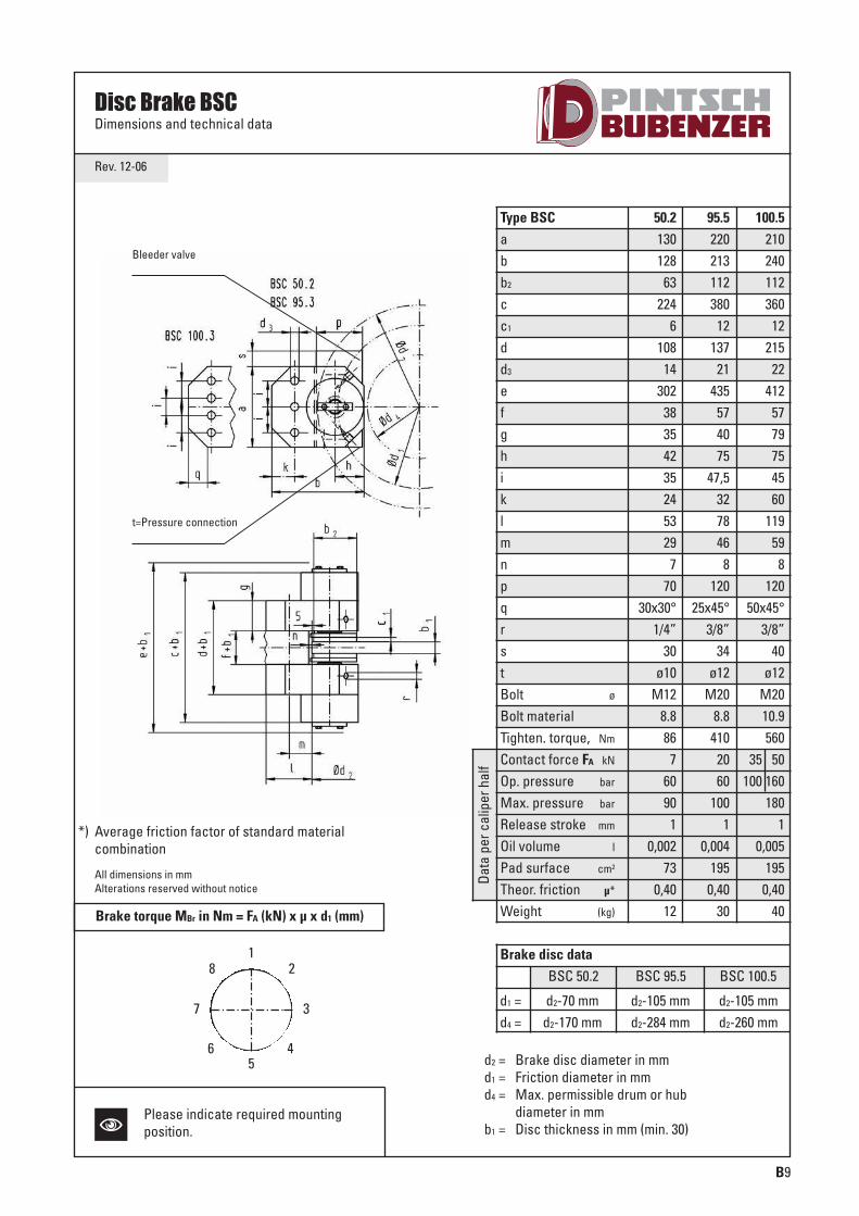
Rev. 12-06
Bleeder valve
t=Pressure connection
Data
per
cal
iper
hal
f
Type BSCabb2
cc1
dd3
efghiklmnpqrstBolt ø
Bolt materialTighten. torque, Nm
Contact force FA kN
Op. pressure bar
Max. pressure bar
Release stroke mm
Oil volume l
Pad surface cm2
Theor. friction µ*
Weight (kg)
50.2130128
63224
6108
14302
38354235245329
770
30x30°1/4”
30ø10
M12 8.886
76090
10,002
730,40
12
95.5220213112380
12137
21435
574075
47,5327846
8120
25x45°3/8”
34ø12
M208.8410
2060
1001
0,0041950,40
30
100.5210240112360
12215
22412
5779754560
11959
8120
50x45°3/8”
40ø12
M2010.9560
35 50100 160
1801
0,0051950,40
40
d2 = Brake disc diameter in mmd1 = Friction diameter in mmd4 = Max. permissible drum or hub
diameter in mmb1 = Disc thickness in mm (min. 30)
d1 =
BSC 50.2 BSC 95.5 BSC 100.5
d2-70 mm d2-105 mm d2-105 mm d4 = d2-170 mm d2-284 mm d2-260 mm
Brake disc data
All dimensions in mmAlterations reserved without notice
*) Average friction factor of standard material combination
128
465
37
Brake torque MBr in Nm = FA (kN) x µ x d1 (mm)
N
Disc Brake BSCDimensions and technical data
Please indicate required mountingposition.
SCHIFFBAU-UK-Innen-0814_pintsch bubenzer 21.08.14 15:03 Seite 13
B10
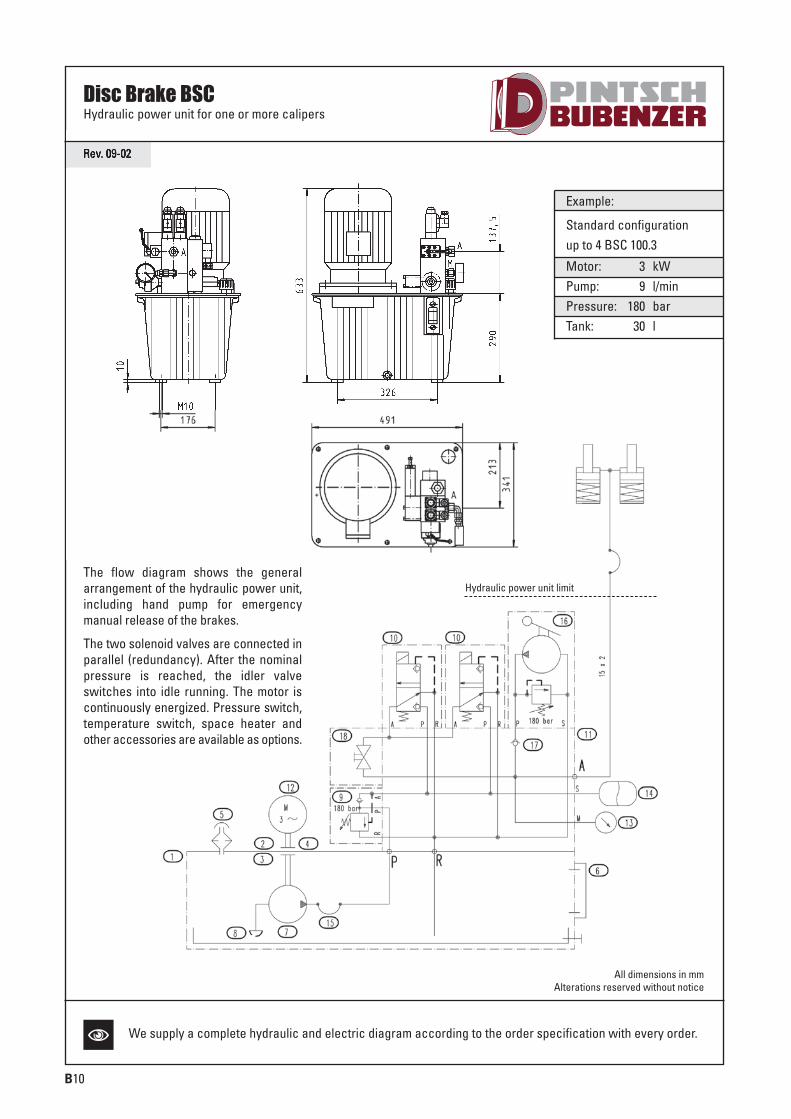
Rev. 09-02
Example:
Standard configurationup to 4 BSC 100.3
Motor: 3 kWPump: 9 l/minPressure: 180 barTank: 30 l
The flow diagram shows the generalarrangement of the hydraulic power unit,including hand pump for emergency manual release of the brakes.
The two solenoid valves are connected inparallel (redundancy). After the nominalpressure is reached, the idler valveswitches into idle running. The motor iscontinuously energized. Pressure switch,temperature switch, space heater andother accessories are available as options.
Hydraulic power unit limit
All dimensions in mmAlterations reserved without notice
N
Disc Brake BSCHydraulic power unit for one or more calipers
We supply a complete hydraulic and electric diagram according to the order specification with every order.
SCHIFFBAU-UK-Innen-0814_pintsch bubenzer 21.08.14 15:04 Seite 14
C1
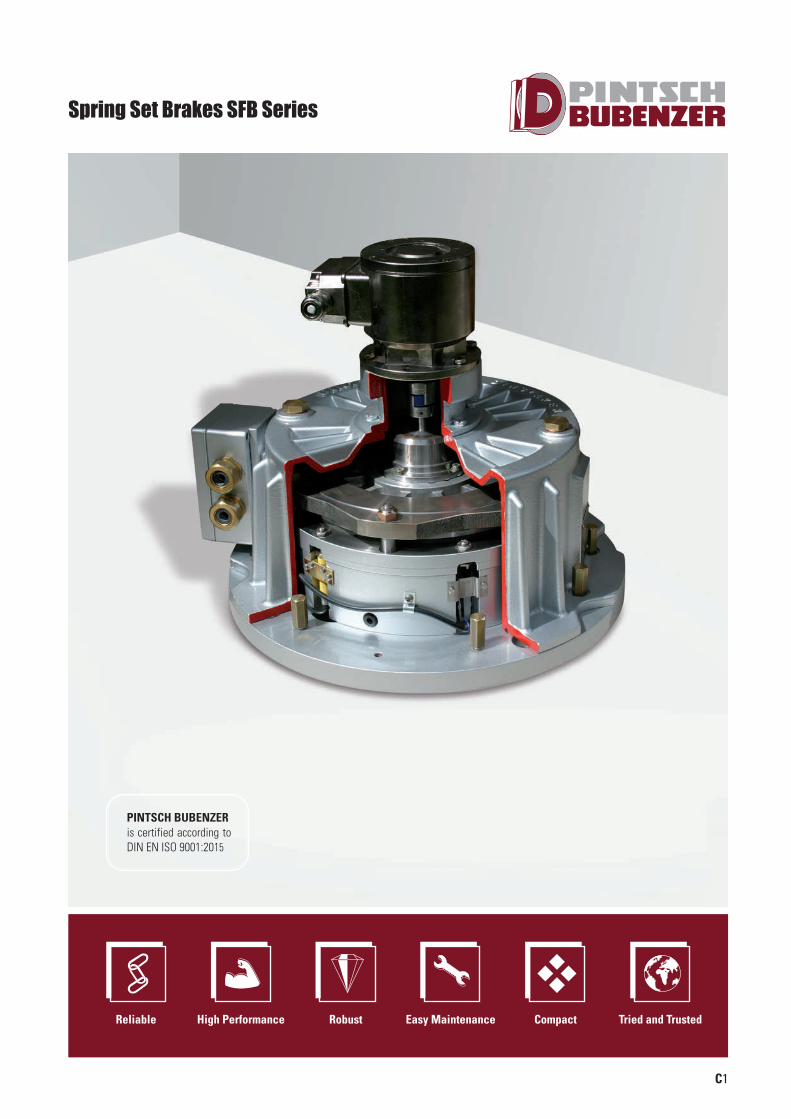
Spring Set Brakes SFB Series
Reliable High Performance Robust Easy Maintenance Compact Tried and Trusted
PINTSCH BUBENZER is certified according to DIN EN ISO 9001:2015
SCHIFFBAU-UK-Innen-0814_pintsch bubenzer 21.08.14 15:04 Seite 15
C2
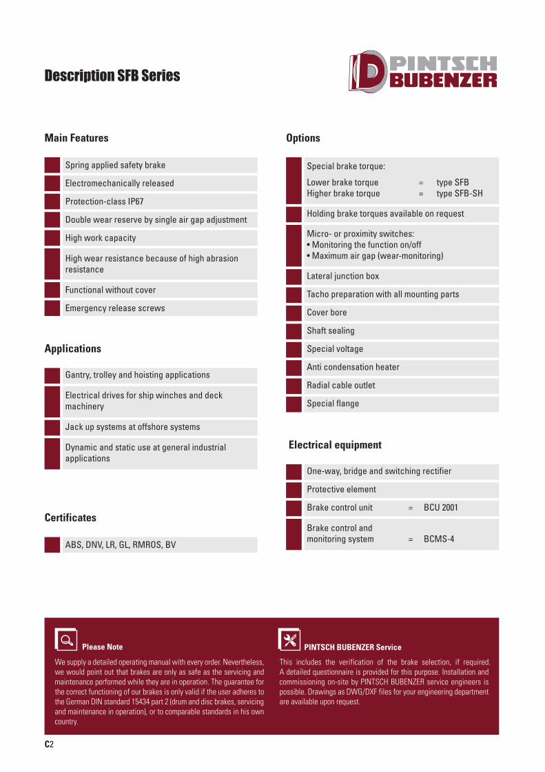
Description SFB Series
Protection-class IP67
Spring applied safety brake
Electromechanically released
Main Features
Gantry, trolley and hoisting applications
Electrical drives for ship winches and deck machinery
Applications
Double wear reserve by single air gap adjustment
Jack up systems at offshore systems
Dynamic and static use at general industrial applications
High work capacity
Functional without cover
Emergency release screws
High wear resistance because of high abrasion resistance
Special brake torque:
Lower brake torque = type SFBHigher brake torque = type SFB-SH
Holding brake torques available on request
Micro- or proximity switches:• Monitoring the function on/off• Maximum air gap (wear-monitoring)
Lateral junction box
Tacho preparation with all mounting parts
Cover bore
Shaft sealing
Special voltage
Anti condensation heater
Radial cable outlet
Options
Special flange
One-way, bridge and switching rectifier
Protective element
Brake control unit = BCU 2001
Brake control and monitoring system = BCMS-4
Electrical equipment
Please Note
We supply a detailed operating manual with every order. Nevertheless,we would point out that brakes are only as safe as the servicing andmaintenance performed while they are in operation. The guarantee forthe correct functioning of our brakes is only valid if the user adheres tothe German DIN standard 15434 part 2 (drum and disc brakes, servicingand maintenance in operation), or to comparable standards in his owncountry.
PINTSCH BUBENZER Service
This includes the verification of the brake selection, if required. A detailed questionnaire is provided for this purpose. Installation and commissioning on-site by PINTSCH BUBENZER service engineers is possible. Drawings as DWG/DXF files for your engineering department are available upon request.
ABS, DNV, LR, GL, RMROS, BV
Certificates
SCHIFFBAU-UK-Innen-0814_pintsch bubenzer 21.08.14 15:04 Seite 16
C3
Rev. 05-08
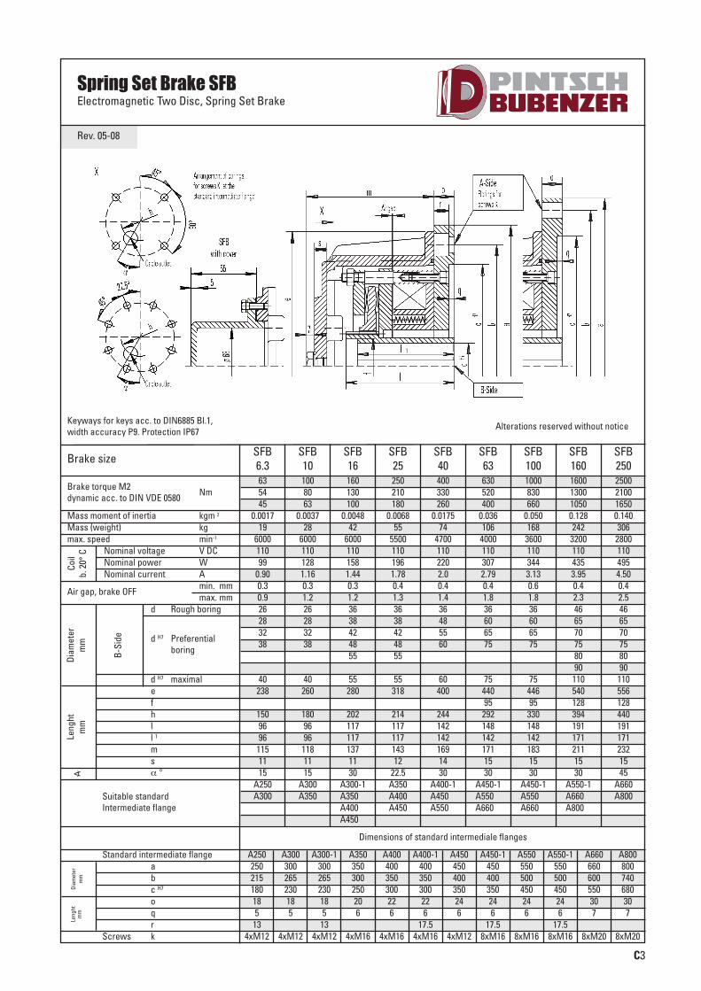
Spring Set Brake SFBElectromagnetic Two Disc, Spring Set Brake
Brake size
Suitable standardIntermediate flange
SFB6.3
SFB10
SFB16
SFB25
SFB40
SFB63
SFB100
SFB160
SFB250
63 100 160 250 400 630 1000 1600 250054 80 130 210 330 520 830 1300 210045 63 100 180 260 400 660 1050 1650
0.0017 0.0037 0.0048 0.0068 0.0175 0.036 0.050 0.128 0.14019 28 42 55 74 106 168 242 306
6000 6000 6000 5500 4700 4000 3600 3200 2800110 110 110 110 110 110 110 110 11099 128 158 196 220 307 344 435 495
0.90 1.16 1.44 1.78 2.0 2.79 3.13 3.95 4.500.3 0.3 0.3 0.4 0.4 0.4 0.6 0.4 0.40.9 1.2 1.2 1.3 1.4 1.8 1.8 2.3 2.526 26 36 36 36 36 36 46 4628 28 38 38 48 60 60 65 6532 32 42 42 55 65 65 70 7038 38 48 48 60 75 75 75 75
55 55 80 8090 90
40 40 55 55 60 75 75 110 110238 260 280 318 400 440 446 540 556
95 95 128 128150 180 202 214 244 292 330 394 44096 96 117 117 142 148 148 191 19196 96 117 117 142 142 142 171 171
115 118 137 143 169 171 183 211 23211 11 11 12 14 15 15 15 1515 15 30 22.5 30 30 30 30 45
A250 A300 A300-1 A350 A400-1 A450-1 A450-1 A550-1 A660A300 A350 A350-1 A400 A450-1 A550-1 A550-1 A660-1 A800
A400-1 A450 A550-1 A660-1 A660-1 A800-1
Dimensions of standard intermediale flanges
A450-1
A250 A300 A300-1 A350 A400 A400-1 A450 A450-1 A550 A550-1 A660 A800250 300 300 350 400 400 450 450 550 550 660 800215 265 265 300 350 350 400 400 500 500 600 740180 230 230 250 300 300 350 350 450 450 550 68018 18 18 20 22 22 24 24 24 24 30 305 5 5 6 6 6 6 6 6 6 7 7
13 13 17.5 17.5 17.54xM12 4xM12 4xM12 4xM16 4xM16 4xM16 4xM12 8xM16 8xM16 8xM16 8xM20 8xM20
Brake torque M2dynamic acc. to DIN VDE 0580 Nm
Mass moment of inertia kgm 2
Mass (weight) kgmax. speed
Coil
b. 2
0° C
Leng
htm
mDi
amet
erm
mLe
nght
mm
Diam
eter
mm
B-Si
de
min-1
Air gap, brake OFFmin. mmmax. mm
d Rough boring
d H7 Preferential boring
Nominal voltage V DCNominal power WNominal current A
d H7 maximalefhll 1
msα °
Standard intermediate flangeabc H7
oqr
Screws k
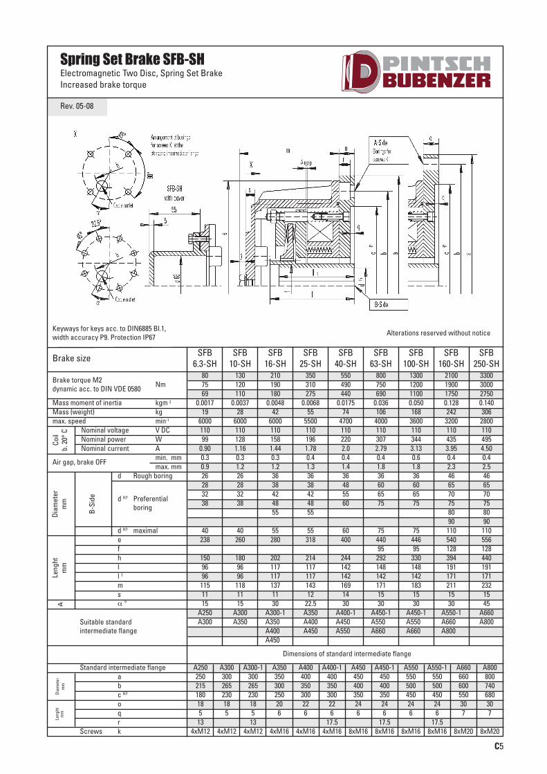
Alterations reserved without noticeKeyways for keys acc. to DIN6885 Bl.1, width accuracy P9. Protection IP67
SCHIFFBAU-UK-Innen-0814_pintsch bubenzer 21.08.14 15:04 Seite 17
C4
Rev. 05-08
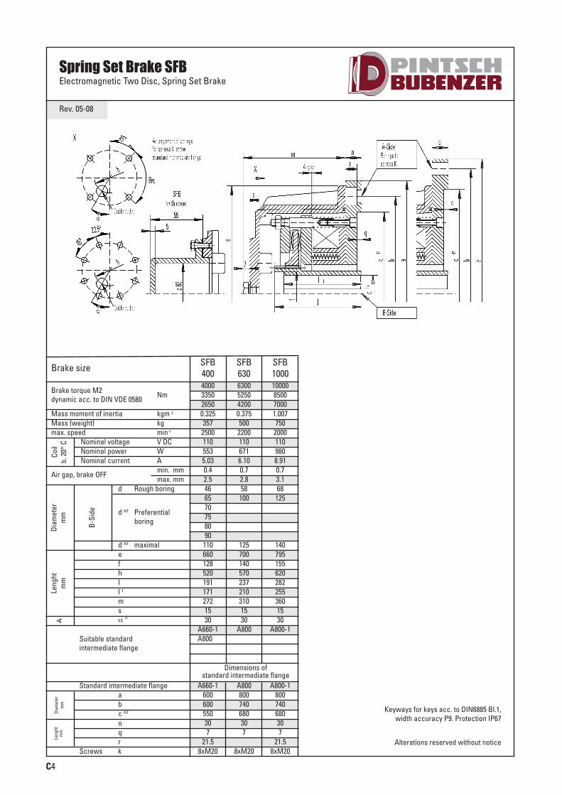
Spring Set Brake SFBElectromagnetic Two Disc, Spring Set Brake
Brake size
Suitable standard intermediate flange
SFB400
SFB630
SFB1000
4000 6300 100003350 5250 85002650 4200 70000.325 0.375 1.007357 500 750
2500 2200 2000110 110 110553 671 9805.03 6.10 8.910.4 0.7 0.72.5 2.8 3.146 58 6865 100 12570758090
110 125 140660 700 795128 140 155520 570 620191 237 282171 210 255272 310 36015 15 1530 30 30
A660-1 A800 A800-1A800-1
Dimensions of standard intermediate flange
A660-1 A800 A800-1600 800 800600 740 740550 680 68030 30 307 7 7
21.5 21.58xM20 8xM20 8xM20
Brake torque M2dynamic acc. to DIN VDE 0580 Nm
Mass moment of inertia kgm 2
Mass (weight) kgmax. speed
Coil
b. 2
0° C
Leng
htm
mDi
amet
erm
mLe
nght
mm
Diam
eter
mm
B-Si
de
min-1
Air gap, brake OFFmin. mmmax. mm
d Rough boring
d H7 Preferentialboring
Nominal voltage V DCNominal power WNominal current A
d H7 maximalefhll 1msα °
Standard intermediate flangeabc H7
oqr
Screws kAlterations reserved without notice
Keyways for keys acc. to DIN6885 Bl.1, width accuracy P9. Protection IP67
SCHIFFBAU-UK-Innen-0814_pintsch bubenzer 21.08.14 15:04 Seite 18
C5
Rev. 05-08
Spring Set Brake SFB-SHElectromagnetic Two Disc, Spring Set BrakeIncreased brake torque
Brake size
Suitable standard intermediate flange
SFB6.3-SH
SFB10-SH
SFB16-SH
SFB25-SH
SFB40-SH
SFB63-SH
SFB100-SH
SFB160-SH
SFB250-SH
80 130 210 350 550 800 1300 2100 330075 120 190 310 490 750 1200 1900 300069 110 180 275 440 690 1100 1750 2750
0.0017 0.0037 0.0048 0.0068 0.0175 0.036 0.050 0.128 0.14019 28 42 55 74 106 168 242 306
6000 6000 6000 5500 4700 4000 3600 3200 2800110 110 110 110 110 110 110 110 11099 128 158 196 220 307 344 435 495
0.90 1.16 1.44 1.78 2.0 2.79 3.13 3.95 4.500.3 0.3 0.3 0.4 0.4 0.4 0.6 0.4 0.40.9 1.2 1.2 1.3 1.4 1.8 1.8 2.3 2.526 26 36 36 36 36 36 46 4628 28 38 38 48 60 60 65 6532 32 42 42 55 65 65 70 7038 38 48 48 60 75 75 75 75
55 55 80 8090 90
40 40 55 55 60 75 75 110 110238 260 280 318 400 440 446 540 556
95 95 128 128150 180 202 214 244 292 330 394 44096 96 117 117 142 148 148 191 19196 96 117 117 142 142 142 171 171
115 118 137 143 169 171 183 211 23211 11 11 12 14 15 15 15 1515 15 30 22.5 30 30 30 30 45
A250 A300 A300-1 A350 A400-1 A450-1 A450-1 A550-1 A660A300 A350 A350-1 A400 A450-1 A550-1 A550-1 A660-1 A800
A400-1 A450 A550-1 A660-1 A660-1 A800-1
Dimensions of standard intermediate flange
A450-1
A250 A300 A300-1 A350 A400 A400-1 A450 A450-1 A550 A550-1 A660 A800250 300 300 350 400 400 450 450 550 550 660 800215 265 265 300 350 350 400 400 500 500 600 740180 230 230 250 300 300 350 350 450 450 550 68018 18 18 20 22 22 24 24 24 24 30 305 5 5 6 6 6 6 6 6 6 7 7
13 13 17.5 17.5 17.54xM12 4xM12 4xM12 4xM16 4xM16 4xM16 8xM16 8xM16 8xM16 8xM16 8xM20 8xM20
Brake torque M2dynamic acc. to DIN VDE 0580 Nm
Mass moment of inertia kgm 2
Mass (weight) kgmax. speed
Coil
b. 2
0° C
Leng
htm
mDi
amet
erm
mLe
nght
mm
Diam
eter
mm
B-Si
de
min-1
Air gap, brake OFFmin. mmmax. mm
d Rough boring
d H7 Preferentialboring
Nominal voltage V DCNominal power WNominal current A
d H7 maximalefhll 1
msα °
Standard intermediate flangeabc H7
oqr
Screws k
Alterations reserved without noticeKeyways for keys acc. to DIN6885 Bl.1, width accuracy P9. Protection IP67
SCHIFFBAU-UK-Innen-0814_pintsch bubenzer 21.08.14 15:04 Seite 19

C6
Rev. 05-08
Spring Set Brake SFB-SHElectromagnetic Two Disc, Spring Set BrakeIncreased brake torque
Brake size
Suitable standard intermediate flange
SFB400-SH
SFB630-SH
SFB1000-SH
5200 8000 130004800 75004400 69000.325 0.375 1.007357 500 750
2500 2200 2000110 110 110553 671 9805.03 6.10 8.910.4 0.7 0.72.5 2.8 3.146 58 6865 100 12570758090
110 125 140660 700 795128 140 155520 570 620191 237 282171 210 255272 310 36015 15 1530 30 30
A660-1 A800 A800-1A800-1
Dimensions of standard intermediate flange
A660-1 A800 A800-1600 800 800600 740 740550 680 68030 30 307 7 7
21.5 21.58xM20 8xM20 8xM20
Brake torque M2dynamic acc. to DIN VDE 0580 Nm
Mass moment of inertia kgm 2
Mass (weight) kgmax. speed
Coil
b. 2
0° C
Leng
htm
mDi
amet
erm
mLe
nght
mm
Diam
eter
mm
B-Si
de
min-1
Air gap, brake OFFmin. mmmax. mm
d Rough boring
d H7 Preferentialboring
Nominal voltage V DCNominal power WNominal current A
d H7 maximalefhll 1msα °
Standard intermediate flangeabc H7
oqr
Screws kAlterations reserved without notice
Keyways for keys acc. to DIN6885 Bl.1, width accuracy P9. Protection IP67
SCHIFFBAU-UK-Innen-0814_pintsch bubenzer 21.08.14 15:04 Seite 20
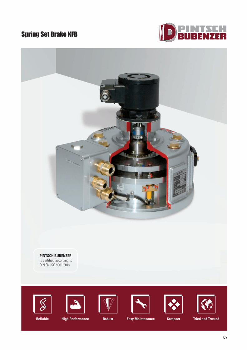
C7
Spring Set Brake KFB
Reliable High Performance Robust Easy Maintenance Compact Tried and Trusted
PINTSCH BUBENZER is certified according to DIN EN ISO 9001:2015
SCHIFFBAU-UK-Innen-0814_pintsch bubenzer 21.08.14 15:04 Seite 21
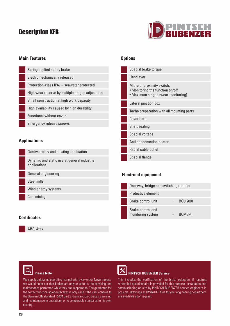
C8
Description KFB
Protection-class IP67 – seawater protected
Main Features
High wear reserve by multiple air gap adjustment
Small construction at high work capacity
Functional without cover
Emergency release screws
High availability caused by high durability
Gantry, trolley and hoisting application
Dynamic and static use at general industrial applications
General engineering
Steel mills
Wind energy systems
Coal mining
Applications
Special brake torque
Handlever
Lateral junction box
Tacho preparation with all mounting parts
Cover bore
Shaft sealing
Special voltage
Anti condensation heater
Radial cable outlet
Special flange
One-way, bridge and switching rectifier
Protective element
Brake control unit = BCU 2001
Brake control and monitoring system = BCMS-4
Options
Spring applied safety brake
Electromechanically released
Micro or proximity switch:• Monitoring the function on/off• Maximum air gap (wear-monitoring)
Electrical equipment
Please Note
We supply a detailed operating manual with every order. Nevertheless,we would point out that brakes are only as safe as the servicing andmaintenance performed while they are in operation. The guarantee forthe correct functioning of our brakes is only valid if the user adheres tothe German DIN standard 15434 part 2 (drum and disc brakes, servicingand maintenance in operation), or to comparable standards in his owncountry.
PINTSCH BUBENZER Service
This includes the verification of the brake selection, if required. A detailed questionnaire is provided for this purpose. Installation and commissioning on-site by PINTSCH BUBENZER service engineers is possible. Drawings as DWG/DXF files for your engineering department are available upon request.
ABS, Atex
Certificates
SCHIFFBAU-UK-Innen-0814_pintsch bubenzer 21.08.14 15:04 Seite 22
C9
Rev. 10-09
Spring Set Brake KFBElectromagnetic Two Disc, Spring Set Brake
Brake size
Suitable standards flanges
KFB10
KFB16
KFB25
KFB30
KFB40
KFB63
KFB100
KFB160
100 160 250 300 400 630 1000 1600
0.0017 0.0037 0.0048 0.0055 0.0068 0.0175 0.036 0.05019 28 42 50 55 74 106 168
6000 6000 6000 6000 5500 4700 4000 3600110 110 110 110 110 110 110 11093 128 158 133 196 220 307 344
0.84 1.16 1.44 1.2 1.78 2.0 2.79 3.130.3 0.3 0.3 0.3 0.3 0.4 0.4 0.41.0 1.0 1.2 0.8 1.2 1.3 1.6 1.826 26 36 26 36 36 36 3628 28 38 32 38 48 60 6032 32 42 38 42 55 65 6538 38 48 42 48 60 75 75
55 45 55
200/250 253/303 300/350 250/300 303/350 350/400 400/450 450/550
Dimensions of standards flanges
A200 A250 A300 A350 A400 A450 A550200 250 300 350 400 450 550165 215 265 300 350 400 500130 180 230 250 300 350 45018 18/20* 20/22* 22 22/24* 24/29* 24/29*5 5 5 6 6 6 6
11 13 13 17.5 17.5 17.5 17.54xM10
A160160130110185
114xM8 4xM12 4xM12 4xM16 4xM16 8xM16 8xM16
Brake torque M2dynamic acc. to DIN VDE 0580 Nm
Mass moment of intertia kgm 2
Mass (weight) kgmax. speed
Coil
b. 2
0° C
Leng
htm
mDi
amet
erm
mLe
nght
mm
Diam
eter
mm
B-Si
de
min-1
Air gap, OFFnorm. mmmax. mm
d pilot bore
d H7 preferrentialbore
Nominal voltage V DCNominal power WNominal current A
efhll 1
msα °
Size of standards flangesabc H7
oqr
Screws k
Alterations reserved without notice.* The larger dimension belongs to the larger assigned brake.
106 144 194 144 194 214 264 314110 96 117 137 117 142 148 155110 96 117 137 117 142 142 142154 141 165 175 175 187 196 21815 15 15 15 15 15 15 1730 30 30 67.5 30 30 30 30
A200 A250 A300 A250 A300 A350 A400 A450A250 A300 A350 A300 A350 A400 A450 A550
KFB5
50
0.001013
600011079
0.720.30.88
152025
160/200
9311011014513
22.5A160A200
SCHIFFBAU-UK-Innen-0814_pintsch bubenzer 21.08.14 15:04 Seite 23

Notes
SCHIFFBAU-UK-Innen-0814_pintsch bubenzer 21.08.14 15:04 Seite 24
C17
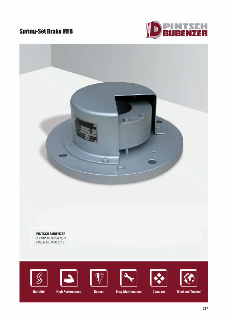
Spring-Set Brake MFB
Reliable High Performance Robust Easy Maintenance Compact Tried and Trusted
PINTSCH BUBENZER is certified according to DIN EN ISO 9001:2015
SCHIFFBAU-UK-Innen-0814_pintsch bubenzer 21.08.14 15:04 Seite 25
C18
Description MFB
Electromagnetic lifting
Main Features
Protection-class IP56
Small construction at high work capacity
Manual lifting
High wear reserve caused by high abrasion resistance
Predominant in static uses at shipbuildingindustry as holding- or safety- brake
Industrial application with requirements ofsmall dimensions at heavy duty applications
Applications
Cast iron cover (IP67)
Special voltage
Cover bore
Tacho preparation
Options
Spring applied safety brake
Please Note
We supply a detailed operating manual with every order. Nevertheless,we would point out that brakes are only as safe as the servicing andmaintenance performed while they are in operation. The guarantee forthe correct functioning of our brakes is therefore only valid if the useradheres to the German DIN standard 15434 part 2 (drum and disc brakes,servicing and maintenance in operation), or to comparable standards inhis own country.
PINTSCH BUBENZER Service
This includes the verification of the brake selection, if required. A detailed questionnaire is provided for this purpose. Installation and commissioning on site is possible by PINTSCH BUBENZER service engineers. Drawings as DWG/DXF files for your engineering department are available upon request.
One-way, bridge and switching rectifier
Protective element
Brake control unit = BCU 2001
Brake control and monitoring system = BCMS-4
Electrical equipment
RMROS
Certificates
SCHIFFBAU-UK-Innen-0814_pintsch bubenzer 21.08.14 15:04 Seite 26
C19
Rev. 05-08
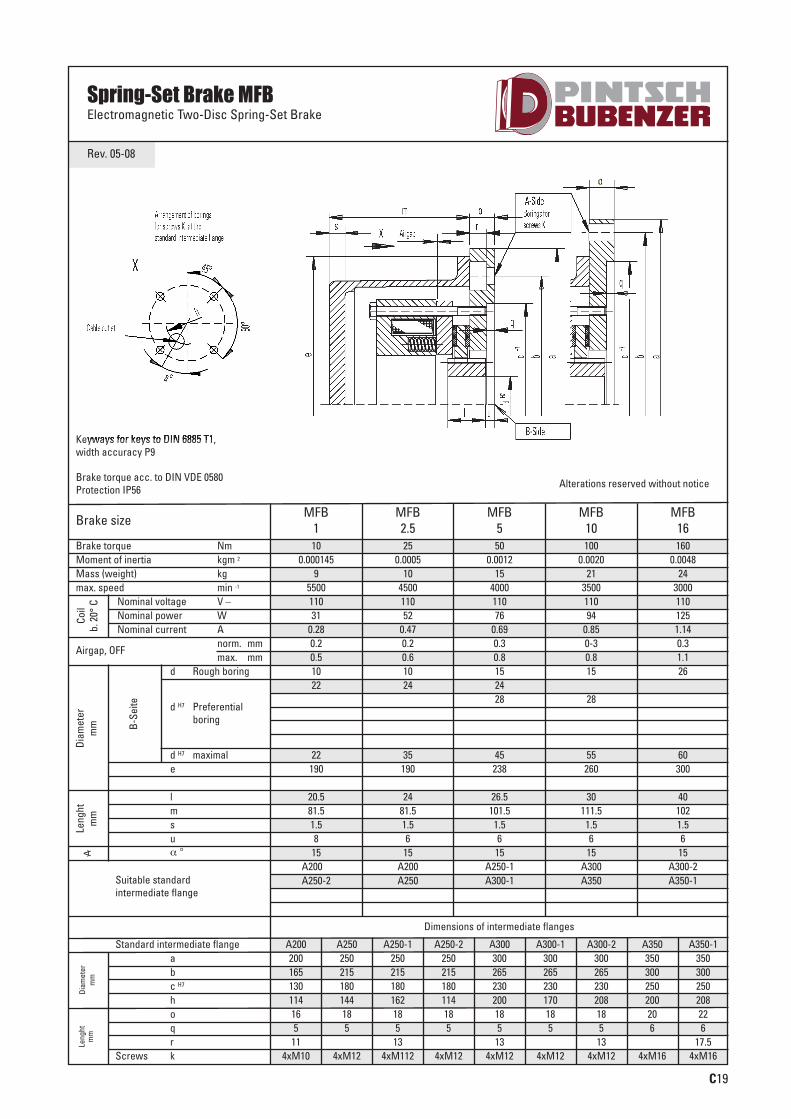
Spring-Set Brake MFBElectromagnetic Two-Disc Spring-Set Brake
Brake size
Suitable standardintermediate flange
MFB1
MFB2.5
MFB5
MFB10
MFB16
10 25 50 100 1600.000145 0.0005 0.0012 0.0020 0.0048
9 10 15 21 245500 4500 4000 3500 3000110 110 110 110 11031 52 76 94 125
0.28 0.47 0.69 0.85 1.140.2 0.2 0.3 0-3 0.30.5 0.6 0.8 0.8 1.110 10 15 15 2622 24 24
28 28
22 35 45 55 60190 190 238 260 300
20.5 24 26.5 30 4081.5 81.5 101.5 111.5 1021.5 1.5 1.5 1.5 1.58 6 6 6 6
15 15 15 15 15A200-2 A200 A250-1 A300 A300-2A250-2 A250 A300-1 A350 A350-1
Dimensions of intermediate flanges
Brake torque NmMoment of inertia kgm 2
Mass (weight) kgmax. speed
Coil
b. 2
0° C
Leng
htm
mD
iam
eter
mm
Leng
htm
mD
iam
eter
mm
B-S
eite
min -1
Airgap, OFFnorm. mmmax. mm
d Rough boring
d H7 Preferentialboring
Nominal voltage V –Nominal power WNominal current A
d H7 maximale
lmsuα °
Standard intermediate flangeabc H7
hoqr
Screws k
Alterations reserved without noticeBrake torque acc. to DIN VDE 0580Protection IP56
Keyways for keys to DIN 6885 T1,width accuracy P9
A200 A250 A250-1 A250-2 A300 A300-1 A300-2 A350 A350-1200 250 250 250 300 300 300 350 350165 215 215 215 265 265 265 300 300130 180 180 180 230 230 230 250 250114 144 162 114 200 170 208 200 20816 18 18 18 18 18 18 20 225 5 5 5 5 5 5 6 6
11 13 13 13 17.54xM10 4xM12 4xM112 4xM12 4xM12 4xM12 4xM12 4xM16 4xM16
SCHIFFBAU-UK-Innen-0814_pintsch bubenzer 21.08.14 15:04 Seite 27

Notes
SCHIFFBAU-UK-Innen-0814_pintsch bubenzer 21.08.14 15:04 Seite 28
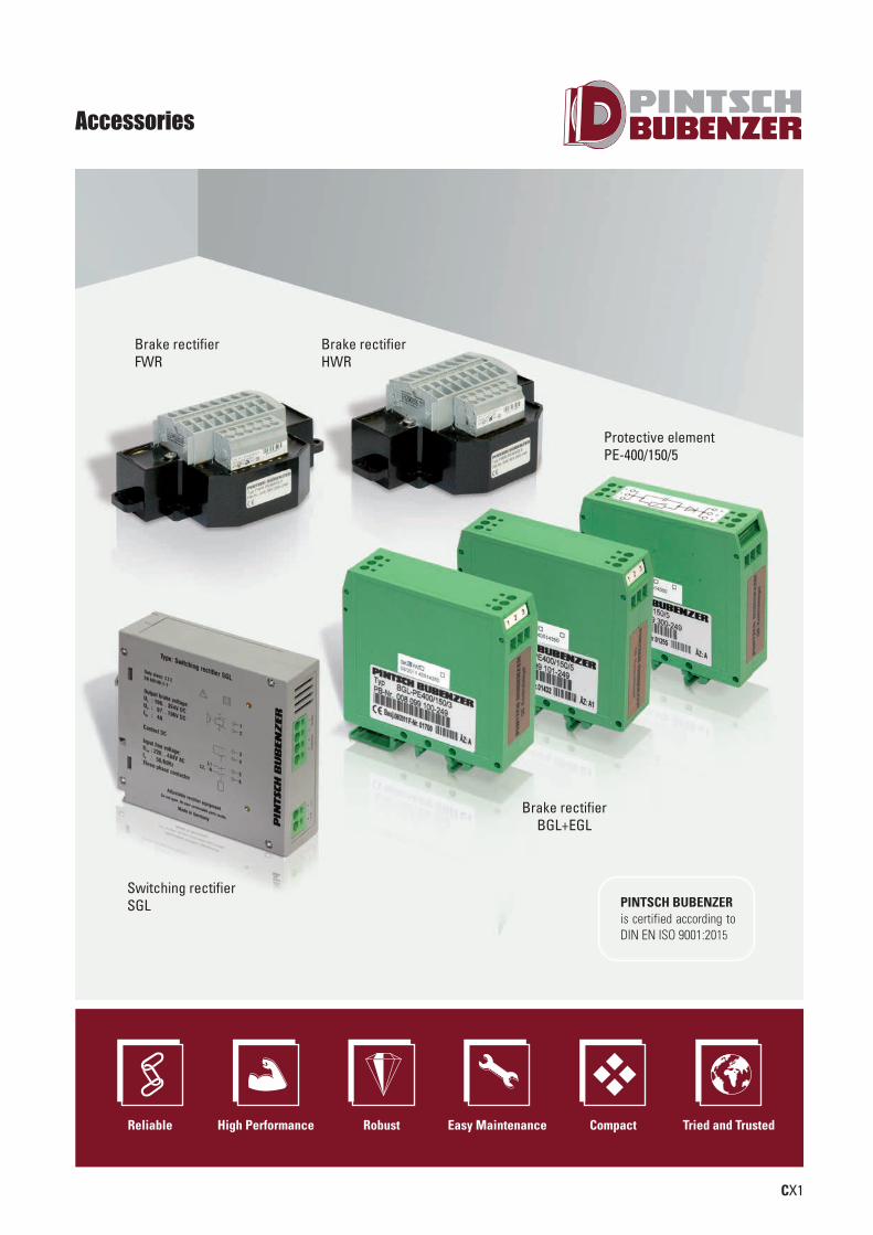
Protective elementPE-400/150/5
Switching rectifierSGL
Brake rectifierBGL+EGL
Brake rectifierHWR
Brake rectifierFWR
CX1
Accessories
PINTSCH BUBENZER is certified according to DIN EN ISO 9001:2015
Reliable High Performance Robust Easy Maintenance Compact Tried and Trusted
SCHIFFBAU-UK-Innen-0814_pintsch bubenzer 21.08.14 15:04 Seite 29
CX2
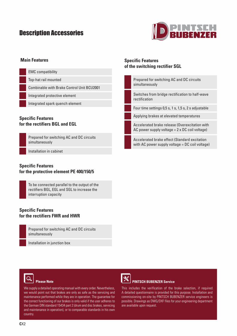
Description Accessories
EMC compatibility
Main Features
Top-hat rail mounted
Combinable with Brake Control Unit BCU2001
Integrated protective element
Integrated spark quench element
Prepared for switching AC and DC circuits simultaneously
Specific Featuresof the switching rectifier SGL
Switches from bridge rectification to half-waverectification
Four time settings 0,5 s, 1 s, 1,5 s, 2 s adjustable
Applying brakes at elevated temperatures
Accelerated brake release (Overexcitation with AC power supply voltage = 2 x DC coil voltage)
Accelerated brake effect (Standard excitation with AC power supply voltage = DC coil voltage)
Please Note
We supply a detailed operating manual with every order. Nevertheless,we would point out that brakes are only as safe as the servicing andmaintenance performed while they are in operation. The guarantee forthe correct functioning of our brakes is only valid if the user adheres tothe German DIN standard 15434 part 2 (drum and disc brakes, servicingand maintenance in operation), or to comparable standards in his owncountry.
PINTSCH BUBENZER Service
This includes the verification of the brake selection, if required. A detailed questionnaire is provided for this purpose. Installation and commissioning on-site by PINTSCH BUBENZER service engineers is possible. Drawings as DWG/DXF files for your engineering department are available upon request.
Prepared for switching AC and DC circuits simultaneously
Specific Features for the rectifiers BGL and EGL
To be connected parallel to the output of the rectifiers BGL, EGL and SGL to increase the interruption capacity
Specific Featuresfor the protective element PE 400/150/5
Prepared for switching AC and DC circuitssimultaneously
Installation in junction box
Specific Featuresfor the rectifiers FWR and HWR
Installation in cabinet
SCHIFFBAU-UK-Innen-0814_pintsch bubenzer 21.08.14 15:04 Seite 30
CX3
Rev. 03-09
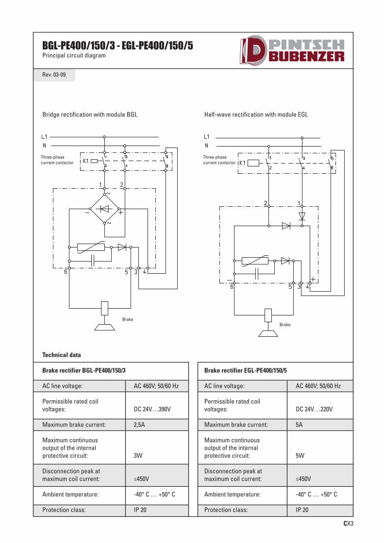
BGL-PE400/150/3 - EGL-PE400/150/5Principal circuit diagram
Technical data
Brake rectifier BGL-PE400/150/3
AC line voltage: AC 460V; 50/60 Hz
Permissible rated coilvoltages: DC 24V…390V
Maximum brake current: 2,5A
Maximum continuousoutput of the internal protective circuit: 3W
Disconnection peak at maximum coil current: ≤450V
Ambient temperature: -40° C … +50° C
Protection class: IP 20
Brake rectifier EGL-PE400/150/5
AC line voltage: AC 460V; 50/60 Hz
Permissible rated coil voltages: DC 24V…220V
Maximum brake current: 5A
Maximum continuous output of the internal protective circuit: 5W
Disconnection peak at maximum coil current: ≤450V
Ambient temperature: -40° C … +50° C
Protection class: IP 20
Bridge rectification with module BGL Half-wave rectification with module EGL
SCHIFFBAU-UK-Innen-0814_pintsch bubenzer 21.08.14 15:04 Seite 31

CX4
Rev. 10-10
Full wave rectifier FWR-PE400/150/3Principal circuit diagram
Technical data
Coil voltage of the connected brake DC 24V ... 390V
Max. voltage of supplying alternating current network AC 460V - 50/60 Hz
Max. Output current Ieff at TA = < 50°C 2,5 A
Max. Output current Ieff at max.TA 85°C 1,8 A
Protection fuse in the AC input voltage line to the rectifier FF 4A(In the selection of fuse is permissible on the I2 t limit load integral to eight) microfuse switching capacity H
Permitted limit integral I2 t 700A² s (t <10ms)
Max. energy absorbation of a shut-off 150 J
Max. continuous power of the internal protective circuit (average value) 3W
Shut-off peak at max. coil current < 450V
Ambiente temperature TA -40° C ... +85° C
Permissible cross section of connection wire 0,2 ... 2,5 mmAWG 24 ... 14
Weight 0,3 kg
Protection class IP 65 components seal / IP20 terminals
Mark of conformity CE / RoHS conform
three-phasecurrent contactor bridge circuit
microfuse
load diagram
Brake
SCHIFFBAU-UK-Innen-0814_pintsch bubenzer 21.08.14 15:04 Seite 32

CX5
Rev. 10-10
Full wave rectifier HWR-PE400/150/5Principal circuit diagram
Technical data
Coil voltage of the connected brake DC 24V ... 240V
Max. voltage of supplying alternating current network AC 550V - 50/60 Hz
Max. Output current Ieff at TA = < 50°C 5 A
Max. Output current Ieff at max.TA 85°C 3,6 A
Protection fuse in the AC input voltage line to the rectifier FF 4A(In the selection of fuse is permissible on the I2 t limit load integral to eight) microfuse switching capacity H
Permitted limit integral I2 t 700A² s (t <10ms)
Max. energy absorbation of a shut-off 150 J
Max. continuous power of the internal protective circuit (average value) 5W
Shut-off peak at max. coil current < 450V
Ambiente temperature TA -40° C ... +85° C
Permissible cross section of connection wire 0,2 ... 2,5 mmAWG 24 ... 14
Weight 0,3 kg
Protection class IP 65 components seal / IP20 terminals
Mark of conformity CE / RoHS conform
three-phasecurrent contactor bridge circuit
microfuse
load diagram
Brake
SCHIFFBAU-UK-Innen-0814_pintsch bubenzer 21.08.14 15:04 Seite 33
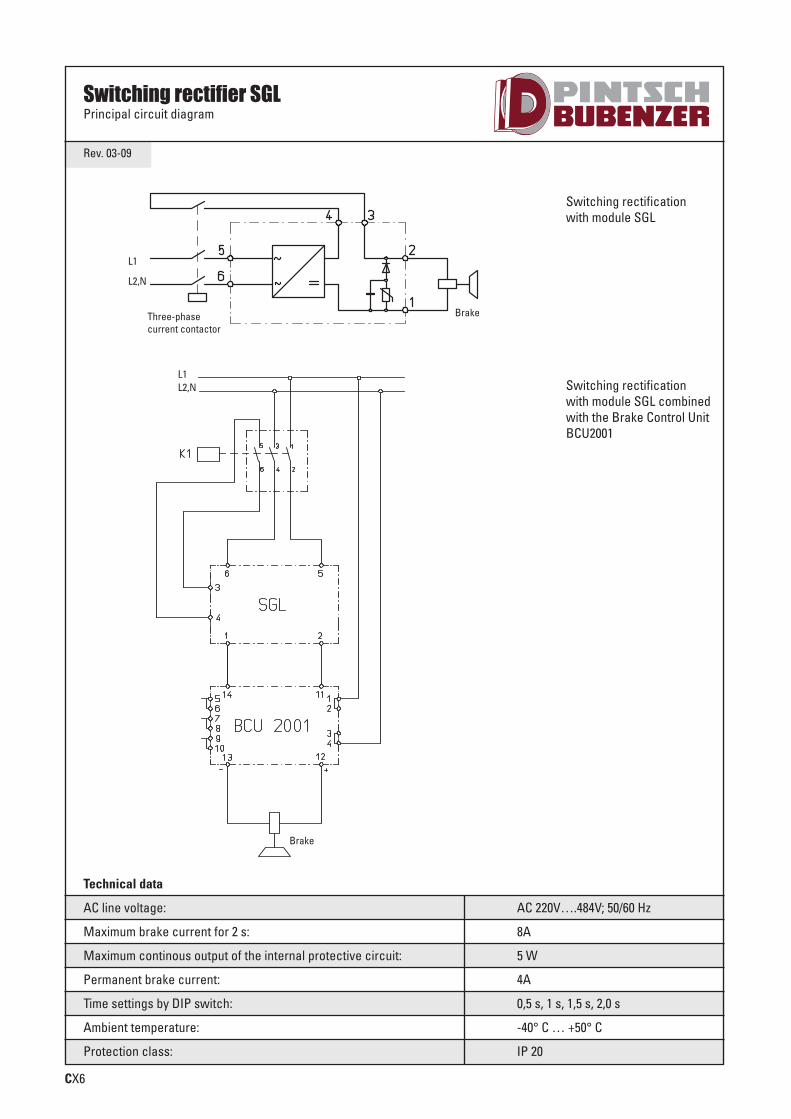
CX6
Technical data
AC line voltage: AC 220V….484V; 50/60 Hz
Maximum brake current for 2 s: 8A
Maximum continous output of the internal protective circuit: 5 W
Permanent brake current: 4A
Time settings by DIP switch: 0,5 s, 1 s, 1,5 s, 2,0 s
Ambient temperature: -40° C … +50° C
Protection class: IP 20
Rev. 03-09
Switching rectifier SGLPrincipal circuit diagram
Switching rectification with module SGL
Switching rectification with module SGL combinedwith the Brake Control UnitBCU2001
SCHIFFBAU-UK-Innen-0814_pintsch bubenzer 21.08.14 15:04 Seite 34
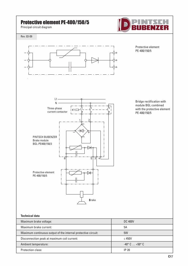
CX7
Technical data
Maximum brake voltage: DC 400V
Maximum brake current: 5A
Maximum continuous output of the internal protective circuit: 5W
Disconnection peak at maximum coil current: ≤ 450V
Ambient temperature: -40° C … +50° C
Protection class: IP 20
Rev. 03-09
Protective element PE-400/150/5Principal circuit diagram
PINTSCH BUBENZERBrake moduleBGL-PE400/150/3
Protective elementPE-400/150/5
Protective elementPE-400/150/5
Bridge rectification withmodule BGL combined with the protective elementPE-400/150/5
SCHIFFBAU-UK-Innen-0814_pintsch bubenzer 21.08.14 15:04 Seite 35

Notes
SCHIFFBAU-UK-Innen-0814_pintsch bubenzer 21.08.14 15:04 Seite 36

Brake Control Unit BCU2001
CX9
PINTSCH BUBENZER is certified according to DIN EN ISO 9001:2015
Reliable High Performance Robust Easy Maintenance Compact Tried and Trusted
SCHIFFBAU-UK-Innen-0814_pintsch bubenzer 21.08.14 15:04 Seite 37
CX10
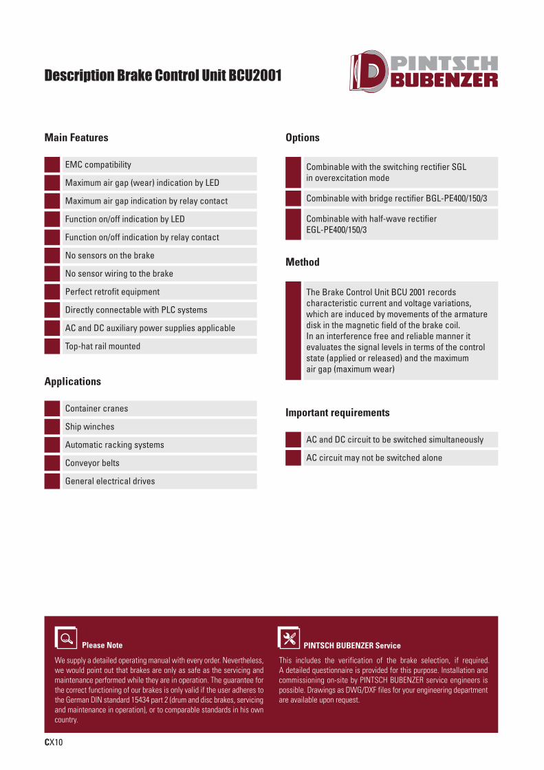
Description Brake Control Unit BCU2001
EMC compatibility
Main Features
Combinable with the switching rectifier SGL in overexcitation mode
Combinable with bridge rectifier BGL-PE400/150/3
Combinable with half-wave rectifier EGL-PE400/150/3
Options
Maximum air gap (wear) indication by LED
Maximum air gap indication by relay contact
Function on/off indication by LED
Function on/off indication by relay contact
No sensors on the brake
No sensor wiring to the brake
Perfect retrofit equipment
Directly connectable with PLC systems
AC and DC auxiliary power supplies applicable
Top-hat rail mounted
Container cranes
Applications
Ship winches
Automatic racking systems
Conveyor belts
General electrical drives
AC and DC circuit to be switched simultaneously
Important requirements
AC circuit may not be switched alone
The Brake Control Unit BCU 2001 records characteristic current and voltage variations,which are induced by movements of the armaturedisk in the magnetic field of the brake coil. In an interference free and reliable manner it evaluates the signal levels in terms of the controlstate (applied or released) and the maximum air gap (maximum wear)
Method
Please Note
We supply a detailed operating manual with every order. Nevertheless,we would point out that brakes are only as safe as the servicing andmaintenance performed while they are in operation. The guarantee forthe correct functioning of our brakes is only valid if the user adheres tothe German DIN standard 15434 part 2 (drum and disc brakes, servicingand maintenance in operation), or to comparable standards in his owncountry.
PINTSCH BUBENZER Service
This includes the verification of the brake selection, if required. A detailed questionnaire is provided for this purpose. Installation and commissioning on-site by PINTSCH BUBENZER service engineers is possible. Drawings as DWG/DXF files for your engineering department are available upon request.
SCHIFFBAU-UK-Innen-0814_pintsch bubenzer 21.08.14 15:04 Seite 38
Technical data
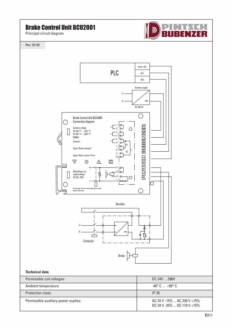
Permissible coil voltages: DC 24V….396V
Ambient temperature: -40° C … +50° C
Protection class: IP 20
Permissible auxiliary power suplies: AC 24 V -15% ... AC 230 V +15%DC 24 V -25% ... DC 110 V +15%
CX11
Rev. 03-09
Brake Control Unit BCU2001Principal circuit diagram
SCHIFFBAU-UK-Innen-0814_pintsch bubenzer 21.08.14 15:04 Seite 39

Notes
SCHIFFBAU-UK-Innen-0814_pintsch bubenzer 21.08.14 15:04 Seite 40
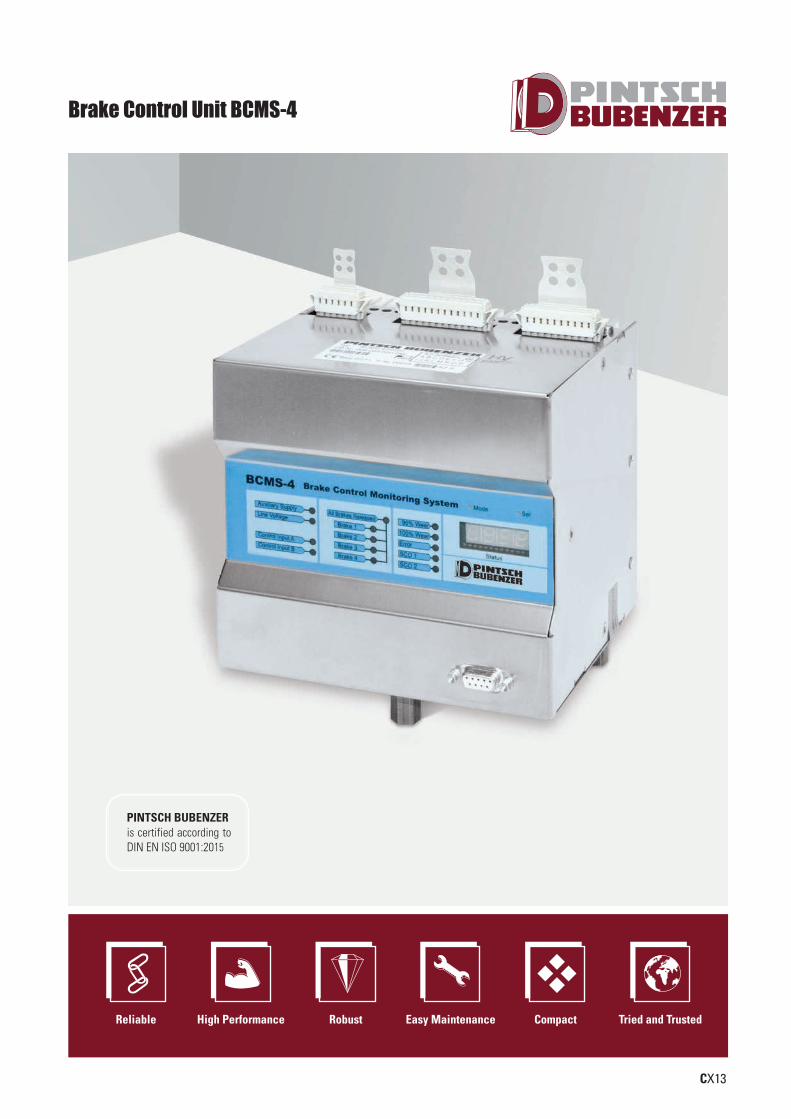
Brake Control Unit BCMS-4
CX13
PINTSCH BUBENZER is certified according to DIN EN ISO 9001:2015
Reliable High Performance Robust Easy Maintenance Compact Tried and Trusted
SCHIFFBAU-UK-Innen-0814_pintsch bubenzer 21.08.14 15:04 Seite 41

CX14
Description Brake Control Unit BCMS-4
Plug and play – minimal configuration and implementation effort
Main Features
No micro- or proximity switches required for thebrake (much lower amount of wiring)
Components such as contactors, power rectifier,suppressor to be omitted (space and cost savings)
Through the use of plug-in terminals a prior installa-tion of the connecting cables is possible (saves time)
Normal maintenance intervals are not required onour brakes (extreme reduction of maintenance costs)
Due to the 4-channel version up to four spring-loaded brakes can be operated simultaneously
Certified safety through professional association
In conjunction with a superior safety PLC operationby security classification DIN EN ISO 13849-1 PL d,Cat 3 is possible
Internal 2-channel safety logic in redundant design
Providing I / O diagnostic outputs for integrationinto PLC
Quick releasing and closing of the brakes
Overcurrent trip to protect the brakes
Wire break recognition
Minimize the power dissipation of the brakes byregulation the holding current
Internal menu structure
Representation of the status wear
User interface RS 232 for connection and interventionin the menu structure
Manual operation of the menu structure
The operating status and diagnostic messages arebe visualized and displayed at the unit itself
Optimization of the wear allowance
„One solution, one source“
The BCMS-4 is a micro-controller-based monitoringand switching device for spring applied brakes ofthe SFB and KFB series. Through measurement and analysis of current and voltage of the outgoingtwo-wire lines of the individual brakes wear andswitching state of each electromagnetic spring-applied brake can be detected in some distantmounting position. There can be up to four brakesoperated and evaluated simultaneously. The operation of the brakes is fundamentally with rapidreleasing and closing of the brakes.
Method
Container cranes
Applications
Ship winches
Automatic racking systems
Conveyor belts
General electrical drives
Please Note
We supply a detailed operating manual with every order. Nevertheless,we would point out that brakes are only as safe as the servicing andmaintenance performed while they are in operation. The guarantee forthe correct functioning of our brakes is only valid if the user adheres tothe German DIN standard 15434 part 2 (drum and disc brakes, servicingand maintenance in operation), or to comparable standards in his owncountry.
PINTSCH BUBENZER Service
This includes the verification of the brake selection, if required. A detailed questionnaire is provided for this purpose. Installation and commissioning on-site by PINTSCH BUBENZER service engineers is possible. Drawings as DWG/DXF files for your engineering department are available upon request.
SCHIFFBAU-UK-Innen-0814_pintsch bubenzer 21.08.14 15:04 Seite 42

CX15
Rev. 11-11
Brake Control Unit BCMS-4Principal circuit diagram
Technical data
Permissible auxiliary power supplies: AC 230V +/- 10%; 50/60 HzAC 400V +/- 10%; 50/60 Hz
Ambient temperature: -30°C …. +50°C
Protection class: IP 20
Permissible coil voltages: 110 V DC and 207 V DC
security rating: DIN EN ISO 13849-1 PL d, Cat 3
PFHD: 1.16-7
SCHIFFBAU-UK-Innen-0814_pintsch bubenzer 21.08.14 15:04 Seite 43

Notes
SCHIFFBAU-UK-Innen-0814_pintsch bubenzer 21.08.14 15:04 Seite 44

Notes
SCHIFFBAU-UK-Innen-0814_pintsch bubenzer 21.08.14 15:04 Seite 45

Notes
SCHIFFBAU-UK-Innen-0814_pintsch bubenzer 21.08.14 15:04 Seite 46

2018 P S H
www.pintschbubenzer.com
INT BUBEN ER
www.pintschbubenzer.com
Content
Hydraulic Disc Brakes B1 - B10
Electromagnetic Disc Brakes C1 - C19
Accessories CX1 - CX7
Brake Control Unit BCU2001 CX9 - CX11
Brake Control Unit BCMS-4 CX13 - CX15

SHIP & OFFSHOREBRAKING UNLIMITED
3rd edition
Made in Germany
PINTSCH BUBENZER GmbH
Friedrichshuettenstr. 1D-57548 Kirchen-WehbachPhone +49 27 41/94 88-0
Huenxer Str. 149D-46537 Dinslaken
Phone +49 20 64/602-0
www.pintschbubenzer.com
Recommended


![REGENERATIVE BRAKING SYSTEM IN ELECTRIC VEHICLES · REGENERATIVE BRAKING SYSTEM IN ELECTRIC VEHICLES ... REGENERATIVE BRAKING SYSTEM ... Regenerative action during braking[9]](https://img.pdfslide.net/doc/110x75/5adccef67f8b9a1a088c7cf0/regenerative-braking-system-in-electric-vehicles-braking-system-in-electric-vehicles.jpg)