Side 1 af 15
10Digital Control Systems
Sampling, Z-transform, transfer function
Reg1_slide4Chap. 13.1-3,4,(5)
J.NyboRev.:14.04.04
Side 2 af 15
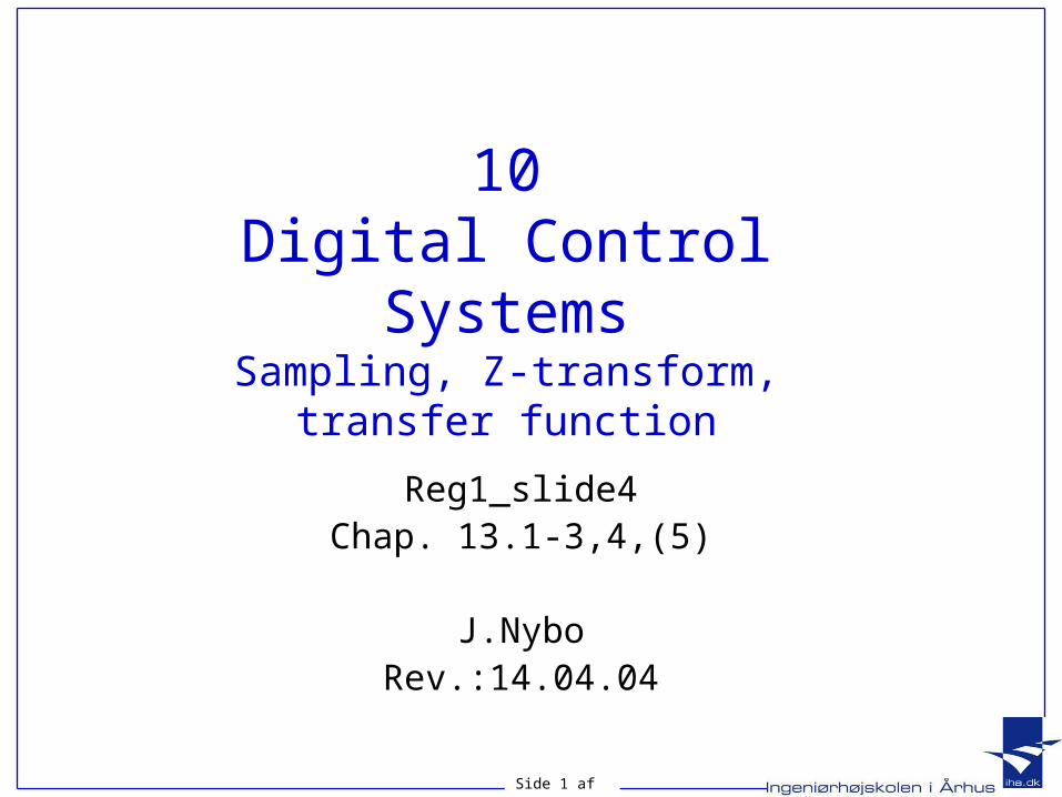
From analog to digital system
Figure 13.1Conversion of antennaazimuth positioncontrol system from:a. analog control tob. digital control

Side 3 af 15
Block-diagram of digital system
Figure 13.2a. Placement of the digital computer within the loop;b. detailed blockdiagram showingplacement of A/D and D/A converters
Side 4 af 15
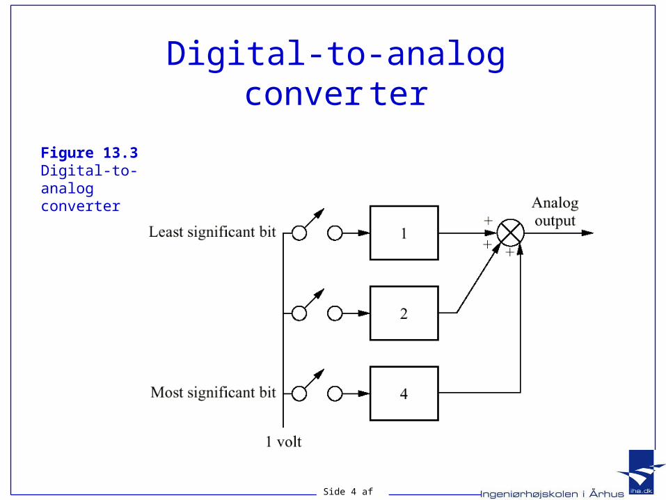
Digital-to-analogconver ter
Figure 13.3Digital-to-analogconverter

Side 5 af 15
Steps in analog-to-digital conversion:
Figure 13.4Steps in analog-to-digital conversion:a. analog signal;b. analog signal after sample-and-hold;c. conversion ofsamples to digitalnumbers
Side 6 af 15
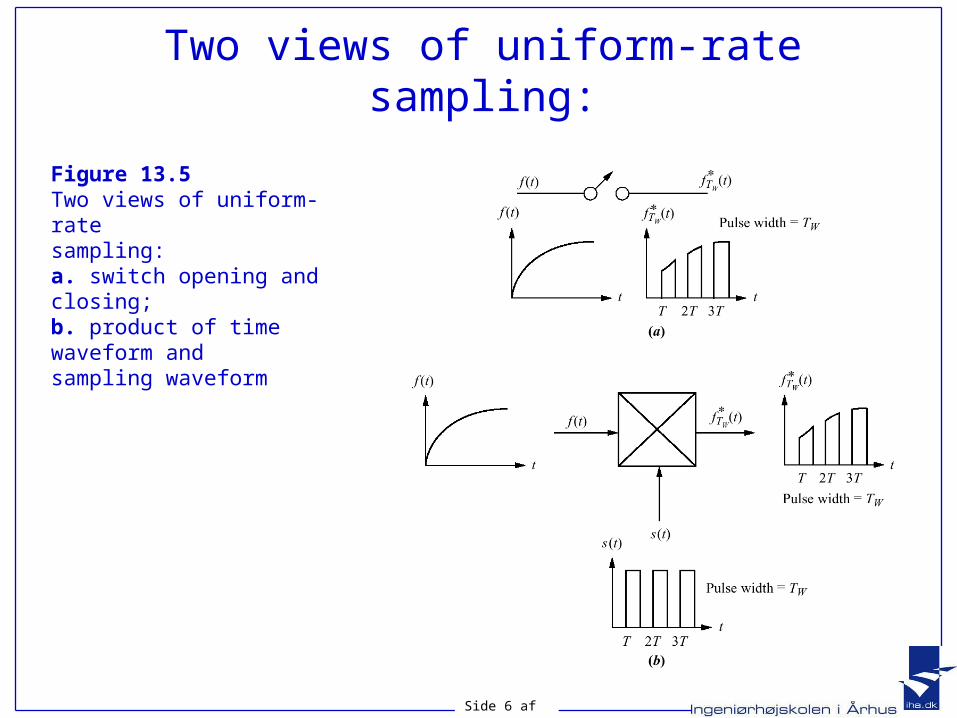
Two views of uniform-rate sampling:
Figure 13.5Two views of uniform-ratesampling:a. switch opening and closing;b. product of timewaveform andsampling waveform
Side 8 af 15
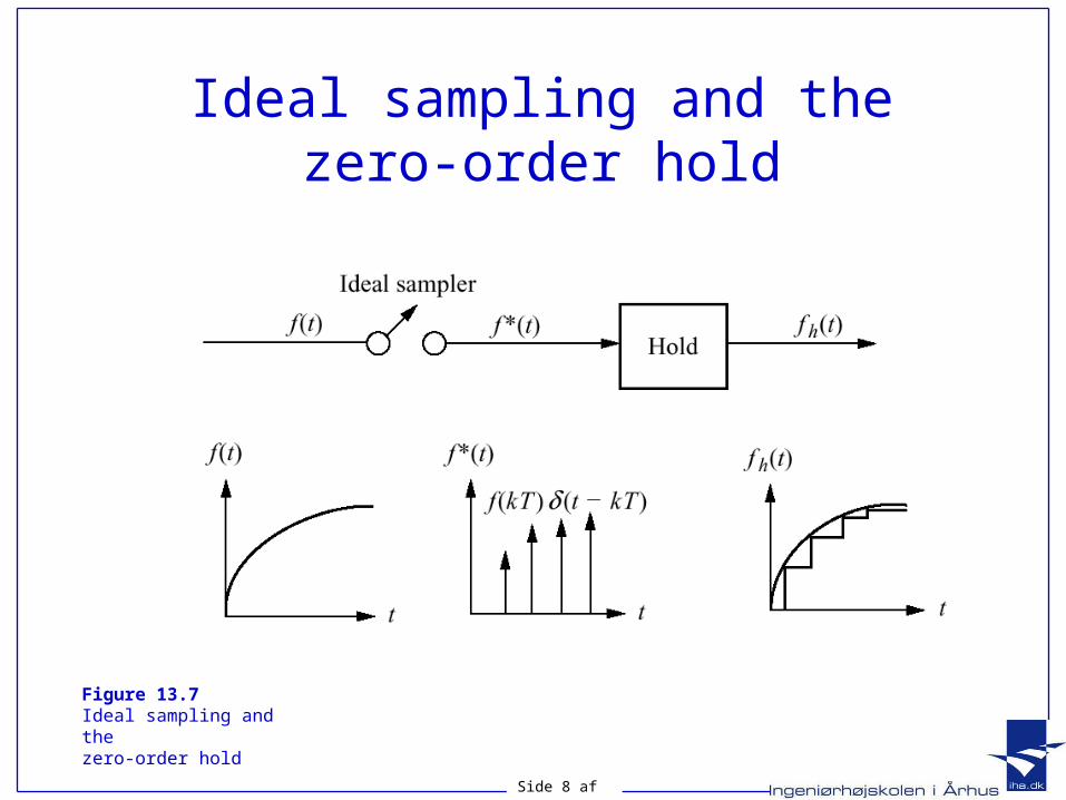
Ideal sampling and thezero-order hold
Figure 13.7Ideal sampling and thezero-order hold
Side 9 af 15
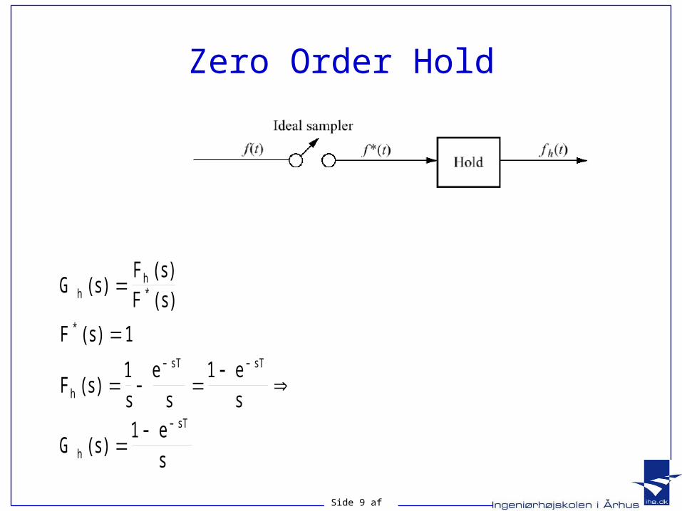
Zero Order Hold
G sF sF s
F s
F ss
es
es
G ses
hh
h
sT sT
h
sT
( )( )( )
( )
( )
( )
*
*
1
1 1
1
Side 10 af 15
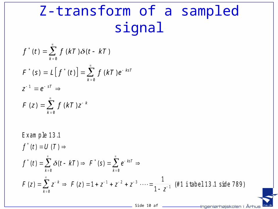
Z-transform of a sampled signal
f t f kT t kT
F s L f t f kT e
z e
F z f kT z
k
ksT
k
sT
k
k
*
* *
( ) ( ) ( )
( ) ( ) ( )
( ) ( )
0
0
1
0
E x am p le 1 3 .1
(# 1 i tab e l 1 3 .1 s id e 7 8 9 )
f t U T
f t t kT F s e
F z z F z z z zz
k
ksT
k
k
k
*
* *
( ) ( )
( ) ( ) ( )
( ) ( )
0 0
0
1 2 311
1
1
Side 11 af 15
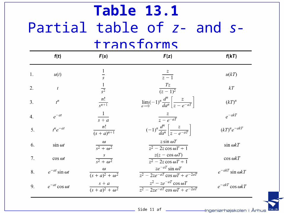
Table 13.1Partial table of z- and s-transforms
Side 12 af 15
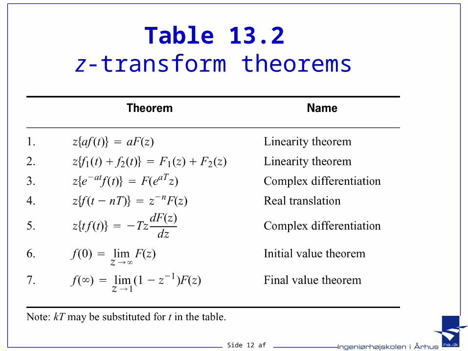
Table 13.2z-transform theorems
Side 13 af 15
Inverse z-transform
• Partial fraction expansion (partial brøker)• Power series (polynomiers division)• Tables

Side 14 af 15
Pulse Transfer Function
Figure 13.8
Sampled-datasystems:a. continuous;b. sampled input;c. sampled inputand output
G zC zR z
( )( )( )
Side 15 af 15
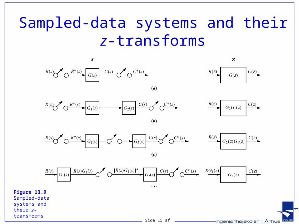
Sampled-data systems and their z-transforms
Figure 13.9Sampled-data systems and their z-transforms
Side 16 af 15
Exercise
• Skill_assesment-Exercise 13.3
Recommended