Komunikasi Data
Local Area Network
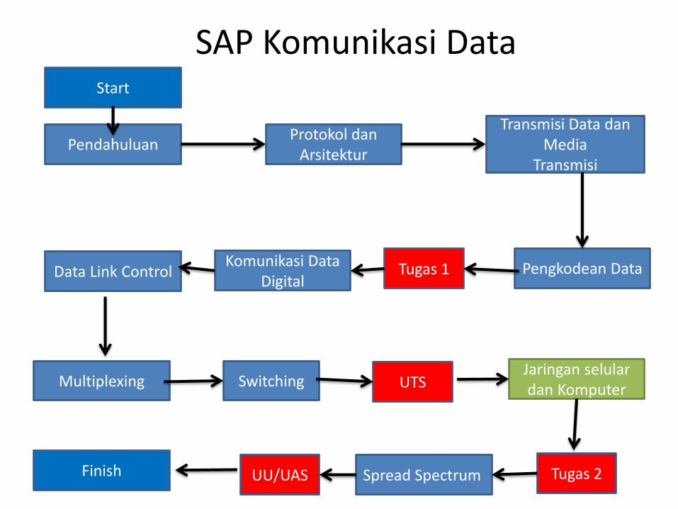
SAP Komunikasi Data
Pendahuluan Protokol dan
Arsitektur
Transmisi Data dan Media
Transmisi
Pengkodean Data Komunikasi Data Digital
Data Link Control
Switching Multiplexing Jaringan selular dan Komputer
Spread Spectrum
Start
Finish
UTS
UU/UAS
Tugas 1
Tugas 2

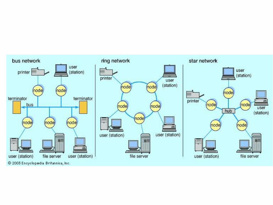
Topologi Jaringan
• Bus Topology
• Star Topology
• Ring Topolgy
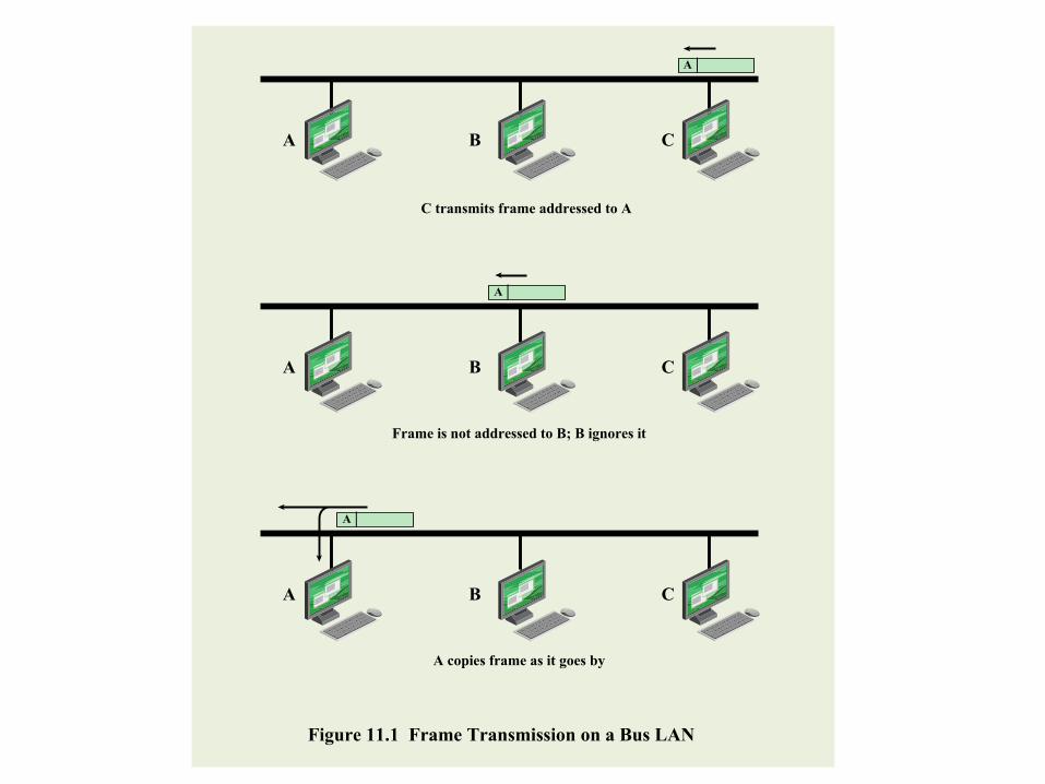
A
A
C transmits frame addressed to A
Frame is not addressed to B; B ignores it
A copies frame as it goes by
A
A
Figure 11.1 Frame Transmission on a Bus LAN
B C
A B C
A B C

Central Hub,
switch,
or repeater
Figure 11.2 Star Topology
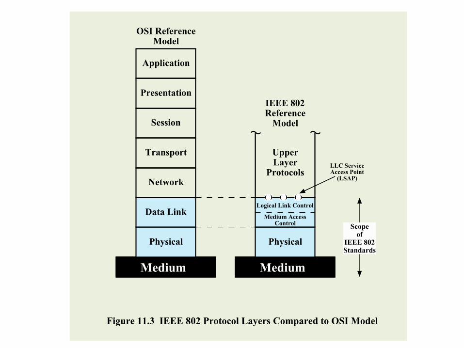
Physical
Data Link
Medium
Network
Transport
Session
Presentation
Application
OSI ReferenceModel
Physical
Medium AccessControl
Medium
Logical Link Control
( ) ( ) ( )
UpperLayer
ProtocolsLLC ServiceAccess Point
(LSAP)
Scopeof
IEEE 802Standards
Figure 11.3 IEEE 802 Protocol Layers Compared to OSI Model
IEEE 802Reference
Model
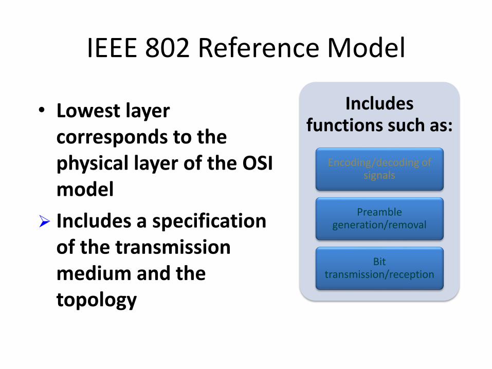
IEEE 802 Reference Model
• Lowest layer corresponds to the physical layer of the OSI model
Includes a specification of the transmission medium and the topology
Includes functions such as:
Encoding/decoding of signals
Preamble generation/removal
Bit transmission/reception

IEEE 802 Layers
• Logical Link Control Layer (LLC) – Provide interface to
higher levels
– Perform flow and error control
• Media Access Control (MAC) – On transmit assemble
data into frame
– On reception disassemble frame, perform address recognition and error detection
– Govern access to LAN transmission medium

TCP segment
IP datagram
LLC protocol data unit
MAC frame
Application data
TCPheader
IPheader
LLCheader
MACheader
MACtrailer
Figure 11.4 LAN Protocols in Context
Application Layer
TCP Layer
IP Layer
LLC Layer
MAC Layer
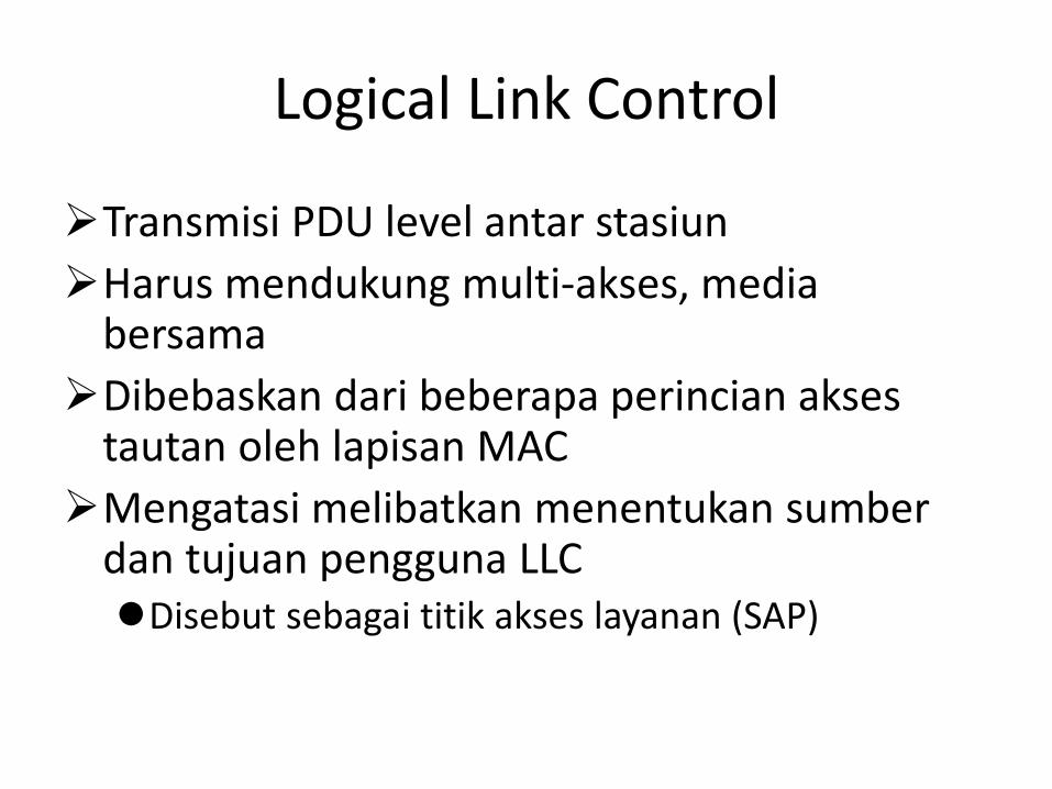
Logical Link Control
Transmisi PDU level antar stasiun
Harus mendukung multi-akses, media bersama
Dibebaskan dari beberapa perincian akses tautan oleh lapisan MAC
Mengatasi melibatkan menentukan sumber dan tujuan pengguna LLC Disebut sebagai titik akses layanan (SAP)

LLC Services
Unacknowledged connectionless service
• Layanan Data-gram
• Pengiriman data tidak dijamin
Connection-mode service
• Logical connection diatur antar 2 pengguna
• Kontrol aliran dan kesalahan disediakan
Acknowledged connectionless service
•Datagrams diketahui, tetapi tidak ada pegaturan logical connection
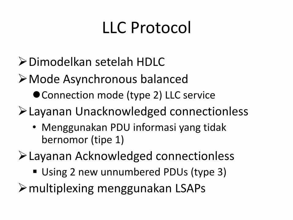
LLC Protocol
Dimodelkan setelah HDLC
Mode Asynchronous balanced Connection mode (type 2) LLC service
Layanan Unacknowledged connectionless • Menggunakan PDU informasi yang tidak
bernomor (tipe 1)
Layanan Acknowledged connectionless Using 2 new unnumbered PDUs (type 3)
multiplexing menggunakan LSAPs
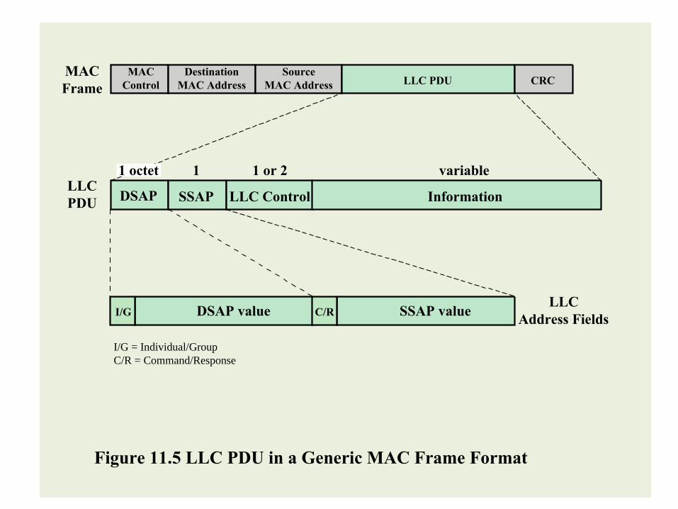
Figure 11.5 LLC PDU in a Generic MAC Frame Format
MAC
Frame
LLC
Address FieldsI/G
I/G = Individual/Group
C/R = Command/Response
DSAP value C/R SSAP value
MAC
Control
Destination
MAC Address
Source
MAC Address LLC PDU CRC
LLC
PDUDSAP
1 octet 1 1 or 2 variable
SSAP LLC Control Information
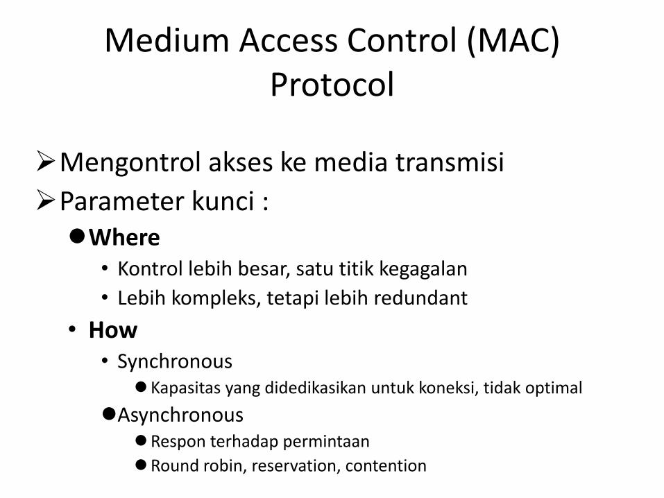
Medium Access Control (MAC) Protocol
Mengontrol akses ke media transmisi
Parameter kunci : Where
• Kontrol lebih besar, satu titik kegagalan
• Lebih kompleks, tetapi lebih redundant
• How • Synchronous
Kapasitas yang didedikasikan untuk koneksi, tidak optimal
Asynchronous Respon terhadap permintaan
Round robin, reservation, contention

Sistem Asynchronous
Round robin
• Each station given turn to transmit data
Reservation
• Divide medium into slots
• Good for stream traffic
Contention
• All stations contend for time
• Good for bursty traffic
• Simple to implement
• Tends to collapse under heavy load

MAC Frame Handling

Bridges
Menghubungkan LAN serupa dengan protokol physical and link layer protocols
Pemrosesan minimal
Dapat memetakan antara format MAC
Alasan Penggunaan:
Reliability
Performance
Security
Geography
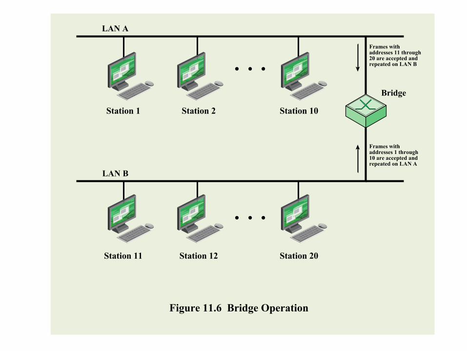
LAN A
LAN B
Bridge
Figure 11.6 Bridge Operation
Frames withaddresses 11 through20 are accepted andrepeated on LAN B
Frames withaddresses 1 through10 are accepted andrepeated on LAN A
Station 1 Station 2 Station 10
Station 11 Station 12 Station 20
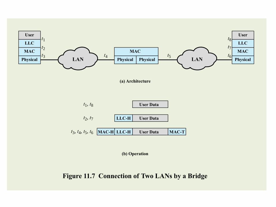
PhysicalPhysical
MAC
MAC-H LLC-H MAC-TUser Data
LLC-H User Data
User Data
LLC
Usert1
t3, t4, t5, t6
t2, t7
t1, t8
t2
t3 t4 t5 t6
t7
t8
Physical
MAC
LLC
User
MAC
(a) Architecture
(b) Operation
Figure 11.7 Connection of Two LANs by a Bridge
PhysicalLAN LAN
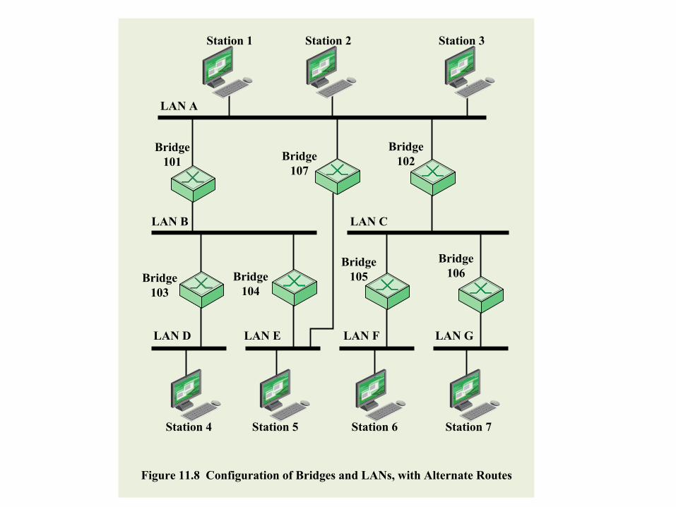
LAN A
LAN B LAN C
LAN D LAN E LAN GLAN F
Bridge
101Bridge
107
Bridge
102
Bridge
103
Bridge
104
Bridge
105
Bridge
106
Station 1
Station 4 Station 5 Station 6 Station 7
Station 2 Station 3
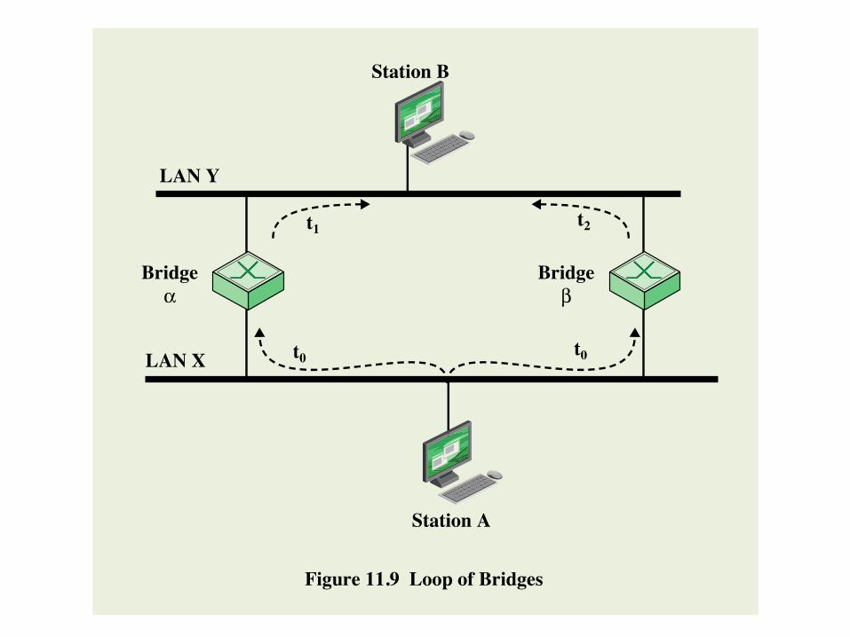
Figure 11.8 Configuration of Bridges and LANs, with Alternate Routes
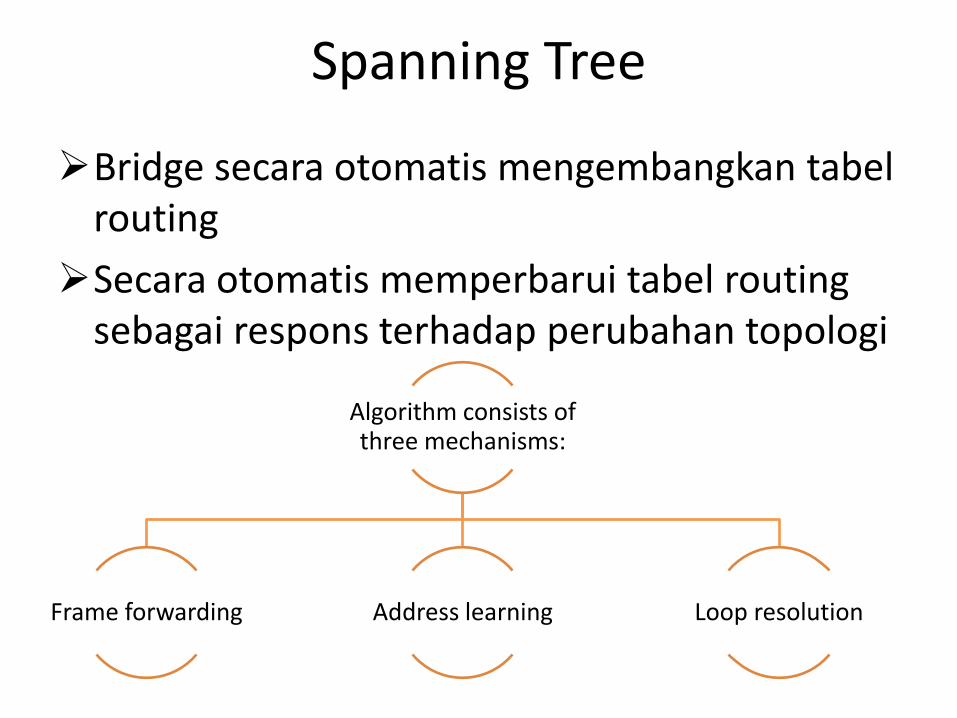
Spanning Tree
Bridge secara otomatis mengembangkan tabel routing
Secara otomatis memperbarui tabel routing sebagai respons terhadap perubahan topologi
Algorithm consists of three mechanisms:
Frame forwarding Address learning Loop resolution

Station Station Station Station
Station
HHUB
Figure 11.10 Two-Level Star Topology
IHUBIHUB
Two cables
(twisted pair or
optical fiber)
Transmit
Receive
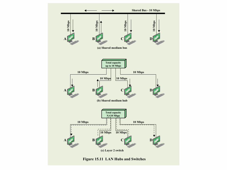
Shared Bus - 10 Mbps
10
Mb
ps
10
Mb
ps
10
Mb
ps
10
Mb
ps
A B C D
(a) Shared medium bus
A B C D
(b) Shared medium hub
10 Mbps 10 Mbps
10 Mbps10 Mbps
Total capacity
up to 10 Mbps
A B C D
(c) Layer 2 switch
10 Mbps 10 Mbps
10 Mbps10 Mbps
Total capacity
N 10 Mbps
Figure 15.11 LAN Hubs and Switches

Figure 11.12 A LAN Configuration
Inaho for takeout. Love to All Tricia
Z
W
XY
Internet
Server
RouterEthernet
switch
Printer
Workstation

Figure 11.13 A Partitioned LAN
Internet
Server
RouterEthernet
switch
Printer
Workstation
Z
V
W
XY

Figure 11.14 A VLAN Configuration
Internet
VLAN
E
VLAN C
VLAN A
VLAN
A
VLAN
A
VLAN
A
VLAN
B
VLAN
B
VLAN
D
Server
Ethernet
switch with
VLAN and
IP routing
capability
Printer
Workstation
Z
W
XY
Recommended