472
SLC30
Series
Combination Display Lights
Highly bright “Super LED” unit improves visibility and safety.
• Eight types of illumination faces to choose from. Compact combination display lights.
• Super bright Super LED.• The fingersafe spring-up terminals reduce
wiring time and prevent electrical shocks.• The insulated jumper, when used on
fingersafe spring-up terminals, eliminates the need of terminal cover.
• Legends can be engraved on the attached marking plate. One or two thin marking sheets (not attached) can also be installed (Type F only).
• Spot illumination available for easy recognition in bright environment (Type F only)
• UL and c-UL recognized, EN compliant.
Type F Type C Type L Type V Type GType F(spot illumination)
Type H(2-way illumination)
An Example of 15-window size
Except for DC-DC converter and resistor types.
1 2 3 4 5 6 7 8 9 10 11 12 13 14 15 16 17 18 19 20 21 22 23 24 25 26
1
2345
6789
10LED Illumination
LED Unit
LED Lamp (SX6S/8 base)For Type C only
BA9S/13Base Lamp
IncandescentIllumination
Application Example of Jumpers
• A wide variety of illumination face sizesType F: 30H × 30W mm (Basic size)Type C: 15H × 30W mm × 2 (Split-window type)Type H: 30H × 60W mmType L: 30H × 90W mmType V: 60H × 30W mmType G: 60H × 60W mmCombined construction is available.
White Screen
Clear MarkingPlate
Spot Light Lens
• Type F WindowSpot Illumination Kit
• Frame (metal)The frame cover and frame are moldedin one piece for one-, two-, and three-window types.
•
• Marking films can be used for Type Fonly
• Available up to 200 windowsLED: 10 rows by 26 columns maximumIncandescent: 10 rows by 20 columns maximum (Type F – LED illumination: 6, 12, 24V AC/DCIncandescent illumination: 6, 12, 18, 24V AC/DC
• The fingersafe, spring-up terminals reduce wiring time.The integrated terminal cover and insulated jumpers prevent electic shocks.
Rows
Columns
Choice of LED or incandescent illumination
Maximum Number of Windows for Incandescent Type
Maximum Numberof Windows for LED Type
• For LED illuminated 110/220V AC type, up to 75 windows (Type F equivalent) can be mounted.
• For incandescent illuminated 110/220V AC type and for Type C, up to 50 windows (Type F equivalent) can be mounted.
• Lighting limitations should be considered in any application.For details see page 499.

ControlUnits
Display Lights
DisplayUnits
SafetyProducts
TerminalBlocks
Comm.Terminals
AS-Interface
Relays & Timers
Sockets
Circuit Protectors
Power Supplies
PLCs & SmartRelay
Operator Interfaces
Sensors
Control Stations
Explosion Protection
References
FlushSilhouette
SLC30
Series
Combination Display Lights
473
Configuration
LED Illuminated IncandescentIlluminated
• See page 501 for the combination of illumination windows. Type F Type C Type H Type L Type V Type G
Illumination Face Types
• Lens (acrylic)
• Marking Plate (acrylic)(clear, white, color)
• Lens Frame (resin)
• Lens (acrylic)
• Marking Plate (acrylic)(clear, white, color)
• Lens Frame (resin)
• See page 501 for details about lens combination.
Spot Illumination(LED illuminated only)
LED Illuminated Incandescent Illuminated
• Mounting ClipSLC-3K1 (supplied)
• Frame CoverBlack (B)
• LED Lamp (for Type C only, SX6S/8 base)Illumination Color: Amber, blue, green, red, white, yellow(2 lamps for 1 window equivalent to Type F)
• LED UnitIllumination Color: Amber, blue, green, red, white, yellow, red/green alternate • Incandescent Lamp
(BA9S/13 base)
LED Illuminated Incandescent Illuminated
•••• One-color full •••• One-color full •••• One-color full •••• Two-color Alternate
•••• One-color full •••• One-color full •••• One-color full
(w/check terminal)
6, 12, 24V AC/DC 24V DC(Except Type C)
24V DC(Type F only)
24V DC(Except Type C)
100/110V DC (Resistor Type)(Except Type C)
100/110V, 200/220V AC(Except Type C)
110V DC (DC-DC Converter Type)(Except Type C)
•••• One-color full
•••• One-color full
•••• One-color full
6, 12, 18, 24V AC/DC(Except Type C)
100/110, 200/220V AC(Except Type C)
110V AC/DC(Except Type C)
(Resistor type)
• 2-way split type is also available in Type H.• The illustration above shows combination examples of windows. One-window type is
available in Type F (see page 477 and 478).
Combination Example of 15 Windows
(Flasher)
LED Illuminated (except for Type C)
• Marking plates include clear marking plate, white screen, color screen, lambda converter, and white marking plate with black coating.
• The order to insert clear marking plate, color screen, and white screen can be interchanged if necessary.
• Markings can be engraved on clear marking plate, white screen, and color screen. Engrave markings on the flat surface of the plate or screen next to the lens.
Note: For white marking plate with black coating, engravea reverse legend on the black-coated surface.
Item Lens Marking Plate(Color Screen) x 2
Display Color
When lamp is off. When lamp is on.
ClearLens
White display when lamp is off.
Clear
White Clear White Specified Color
Color display when lamp is off.
Color Screen (use clear screen for white)
White Specified Color Specified Color
Lambda Converter White Lambda
Converter White Pure White
Gray Lens GrayWhite marking plate with black coating (Note)
Clear Gray Specified Color for legend
Incandescent Illuminated and LED Illuminated Type C
• The order to insert clear marking plate, color screen, and white screen can be interchanged if necessary.
• Markings can be engraved on clear marking plate, white screen, and color screen. Engrave markings on the flat surface of the plate or screen next to the lens.
Note: For white marking plate with black coating, engrave a reverse legend on the black-coated surface.
Item Lens Marking Plate(Color Screen) x 2
Display Color
When lamp is off. When lamp is on.
ClearLens
White display when lamp is off. Clear White Color
Screen (use clear screen for white)
White
Specified Color
Gray GrayWhite marking plate with black coating (Note)
Specified Color for Legend
(H)
(V)
(F)
(G)
(L)
(F)
(C)(C)

SLC30
Series
Combination Display Lights
474
Specifications (SLC30 Series)
•
LED
Illuminated
Specify a color code in place of
∗
.Note 1: The rated voltage for w/check terminal type is 24V DC only. Note 5: Blue LED is 24V AC/DC only. Pure white illumination uses blue LED units.Note 2: Terminal cover is available (see page 493). Note 6: Multiple flasher type units do not synchronize with each other.Note 3: 50/60Hz with AC voltage type. Note 7: No freezingNote 4: Including pure white.
•
Incandescent Illuminated
Note 1: 50/60Hz with AC voltage type.Note 2: Terminal cover is available for all incandescent illuminated types (see page 493), except for the resistor type.
•
LED/Incandescent Illuminated
Note 1: Flasher type, pure white illumination, and spot illumination types are available in Type F only.Note 2: 2-way split type (Type H2) can use 2-way split color screen only.
Light Source LED Unit LED Lamp
Input Type Full Voltage Transformer DC-DC Converter
Resistor Full Voltage
Illumination Type One-colorOne-color w/check terminal (Note 1)
Two-color Alternate Flasher Type One-color One-color
×
2Split-window Type (Type C)
Fingersafe Spring-up Terminal Provided (except for check terminal) —
(Note 2) Provided —(Note 2)
Rated Voltage (Note 3) 6V AC/DC ±5%
12V AC/DC±10%
24V AC/DC±10%
24V DC ±10%
24V DC±10%
100/110V AC±10%
200/220V AC±10%
110V DC(90 to 140V
DC)
100/110VAC/DC ±10%
6V AC/DC ±10%
12V AC/DC±10%
24V AC/DC±10%
Maximum Current Draw (VA) Same as internal LED unit — 1.7 1.4 1.5 Same as internal LED
Illumination Color Amber, green, red, white, yellow
Amber, blue, green, pure white, red,
white, yellow
Red/green Alternate Amber, blue, green, pure white, red, white, yellow Amber, blue, green, red, white, yellow
Standards UL, c-UL listed, EN compliant — —
Bui
lt-in
LE
D U
nit/L
amp
Rated Voltage 6V AC/DC 12V AC/DC 24V AC/DC 24V DC 24V AC/DC 6V AC/DC 12V AC/DC 24V AC/DC
Rat
ed C
urre
nt Red, white, yellow 43 mA 23 mA 13 mA
Red:13 mAGreen:12 mA
13 mA
7 mA 8 mA 8 mAAmber, blue, green 39 mA 21 mA 12 mA
(Note 4) 12 mA (Note 4)
Illumination Color (code)
Amber (A), blue (S), green (G), red (R), white (W), yellow (Y) (Note 5)
Red (R)/green (G)
Amber (A), blue (S), green (G),red (R), white (W), yellow (Y)
Amber (A), blue (S), green (G),red (R), white (W), yellow (Y)
Base Plug-in unit type SX6S/8
Type No. (See page 496) SLDN-32F-
∗
T LFTD-6
∗
LFTD-1
∗
LFTD-2
∗
No. of Units 1 LED unit per window of basic Type F 1 LED lamp per split-window type
Flashing Period —0.5 ±0.2 sec
(fixed duty 1:1) (Note 6)
— —
Insulation Resistance 100 M
Ω
between live and dead parts (500V DC megger)
Dielectric Strength 2000V AC (1 minute) between live and dead parts 2500V AC (1 minute)between live and dead parts
2000V AC (1 minute)
2000V AC (1 minute)between live and dead parts
Operating Temperature (Note 7) –20 to +40°C –10 to +40°C –20 to +40°C –10 to +40°C –20 to +40°C –20 to +40°C
Operating Humidity 45 to 85% RH (no condensation)
Illumination Type One-colorFull Voltage
One-colorTransformer
One-colorResistor
Rated Voltage (Note 1) 6V AC/DC 12V AC/DC 18V AC/DC 24V AC/DC 100/110, 200/220V AC 110V AC/DC
Illumination Color Amber, blue, green, red, white, yellow
Built-inLamp
Rated Voltage 6.3V·1W lamp 18V·1W lamp 24V·1W lamp 30V·1W lamp 6.3V·1W lamp 18V·1W lamp
Operating Voltage 5 to 6V 12 to 18V 18 to 24V 24 to 30V 5 to 6V 12 to 18V
Base BA9S/13
Type No. LS-6 LS-8 LS-2 LS-3 LS-6 LS-8
No. of Lamps 1 lamp per window of basic Type F
Insulation Voltage 100 M
Ω
between live and dead parts (500V DC megger)
Dielectric Strength 2000V AC (1 minute) between live and dead parts 2500V AC (1 minute)between live and dead parts
2000V AC (1 minute)between live and dead parts
Operating Temperature –20 to +40°C (no freezing)
Operating Humidity 45 to 85% RH (no condensation)
Illumination Face Type Type F (Note 1) (Basic Type)
Type C(Split-window Type) Type H Type L Type V Type G
Illu
min
atio
n U
nit
Siz
e (m
m)
Window (H
×
W) 30
×
30 15
×
30 30
×
60 30
×
90 60
×
30 60
×
60
Illumination Face (H
×
W) 28
×
28 13
×
28 28
×
58 28
×
88 58
×
28 58
×
58
White color screen,clear marking plate,color screen (H
×
W
×
t)27
×
27
×
1.0 12
×
27
×
1.0 27
×
57
×
1.0 (Note 2) 27
×
87
×
1.0 57
×
27
×
1.0 57
×
57
×
1.0
Marking Film Applicable — — — — —
Engraving Area(white, transparent,color plates)
25
×
25 10
×
25 25
×
55 25
×
85 55
×
25 55
×
55
Material of Marking Plate & Color Screen Acrylic
Lens Frame Color & Frame Cover Color Black (Munsell N1.5 equivalent)
Connection Wire Solid wire: ø1.6
×
2, Stranded 2 mm
2
×
2
Terminal Screw M3.5 screw, Incandescent resistor: M4 nut, Check terminal: M3
Degree of Protection IP40
Pollution Degree 3
ControlUnits
Display Lights
DisplayUnits
SafetyProducts
TerminalBlocks
Comm.Terminals
AS-Interface
Relays & Timers
Sockets
Circuit Protectors
Power Supplies
PLCs & SmartRelay
Operator Interfaces
Sensors
Control Stations
Explosion Protection
References
FlushSilhouette
SLC30
Series
Combination Display Lights
475
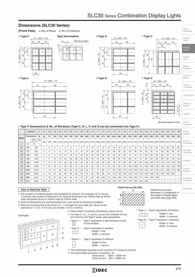
Dimensions (SLC30 Series)
•
Type F Dimensions & No. of Windows (Type C, H, L, V, and G can be converted into Type F.)
Columns
b 01 02 03 04 05 06 07 08 09 10 11 12 13 14 15 16 17 18 19 20 21 22 23 24 25 26
RowsDimensions B 42 72 102 132 162 192 222 252 282 312 342 372 402 432 462 492 522 552 582 612 642 672 702 732 762 792
Panel Cut-out
(D)
(35) (65) (95) (125) (155) (185) (215) (245) (275) (305) (335) (365) (395) (425) (455) (485) (515) (545) (575) (605) (635) (665) (695) (725) (755) (785)
a
A
(C)
01
42
(35) 1 2 3 4 5 6 7 8 9 10 11 12 13 14 15 16 17 18 19 20 21 22 23 24 25 26
02
72
(65) 2 4 6 8 10 12 14 16 18 20 22 24 26 28 30 32 34 36 38 40 42 44 46 48 50 52
03
102
(95) 3 6 9 12 15 18 21 24 27 30 33 36 39 42 45 48 51 54 57 60 63 66 69 72 75 78
04
132
(125) 4 8 12 16 20 24 28 32 36 40 44 48 52 56 60 64 68 72 76 80 84 88 92 96 100 104
05
162
(155) 5 10 15 20 25 30 35 40 45 50 55 60 65 70 75 80 85 90 95 100 105 110 115 120 125 130
06
192
(185) 6 12 18 24 30 36 42 48 54 60 66 72 78 84 90 96 102 108 114 120 126 132 138 144 150 156
07
222
(215) 7 14 21 28 35 42 49 56 63 70 77 84 91 98 105 112 119 126 133 140 147 154 161 168 175 182
08
252
(245) 8 16 24 32 40 48 56 64 72 80 88 96 104 112 120 128 136 144 152 160 168 176 184 192 200 —
09
282
(275) 9 18 27 36 45 54 63 72 81 90 99 108 117 126 135 144 153 162 171 180 189 198 — — — —
10
312
(305) 10 20 30 40 50 60 70 80 90 100 110 120 130 140 150 160 170 180 190 200 — — — — — —
A =
(60
a +
12)
B = (30b + 12)
21 30 30
30
3660
60
A =
(30a +
12) 21
30
30
30
30
B = (30b + 12)
21 30 30 5.3
5.5
Spot Illumination
36 60
3660
60
B = (60b + 12)
A =
(60
a +
12)
A =
(30
a +
12)
B = (60b + 12)
36 60
2130
30
30
60
A =
(30
a +
12)
B = (90b + 12)
51 90
2130
30
30
90
A =
(30
a +
12)
B = (30b + 12)
21 30 30
30
13.5
1515
1515
[Front View] a: No. of Rows b: No. of Columns
•••• Type F Spot Illumination •••• Type H •••• Type V
•••• Type L •••• Type G •••• Type C
All dimensions in mm.
C F
F F
HH
GV
L
CCC
12 3 4 5 6
1
2
3
1. The number of windows equals rows multiplied by columns. For example, for 5 rows by7 columns, the number of windows is 35, external dimensions are 162mm high by 22mm wide, and panel cut-out is 155mm high by 215mm wide.
2. External dimensions are represented by A for rows and B for columns in boldface.3. Panel cut-out dimensions are shown in ( ), for height (C) and width (D). Panel cut-out
tolerance is +1.0 to –0 mm (for one window: +0.6 to –0.4mm).
How to Read the Table
4. Total number of windows, dimensions, panel cut-out➀ For Type C, H, L, V, and G, convert the numbers of rows
and columns into Type F (basic size) equivalents.
• Type C — Type F equivalent: 2 split-windows consistof one window.
• Type H — Type F equivalent: 2 windows
• Type V — Type F equivalent: 2 windows.
➁ The combination example at left consists of 3 rows by 6 columns.➂ The above table shows:No. of windows: 18
Dimensions: 102H × 192W mmPanel cut-out: 95H × 185W mm
Height: 1 rowWidth: 2 columns
Height: 2 rowsWidth: 1 column
Panel Cut-out (SLC30)D
C
• Type L — Type F equivalent: 3 windows
• Type G — Type F equivalent: 4 windows
Height: 1 rowWidth: 3 columns
Height: 2 rowsWidth: 2 columns
[Example]
Determine the panel thickness in consideration of the weight of display lights and wires (see page 493).
SLC30
Series
Combination Display Lights
476
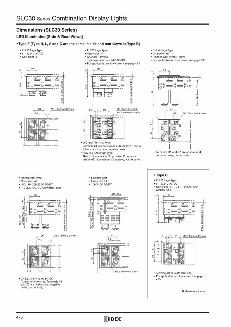
Dimensions (SLC30 Series)
LED Illuminated [Side & Rear Views]
•••• Type F (Type H, L, V, and G are the same in side and rear views as Type F.)
30659
.5
30682
8
30
1430
M3 Check Terminal
M3.5 Terminal Screws M3.5 Terminal Screws
1430
6.2 4 30
30
6
P
anel
Thi
ckne
ss 0
.8 to
6
P
anel
Thi
ckne
ss 0
.8 to
6
Pan
el T
hick
ness
0.8
to 6
55.5
1430
30
9.2
M3.5 Terminal Screws
• Full Voltage Type • 6, 12, 24V AC/DC• One-color full
• Full Voltage Type• One-color full• w/Check Terminal• Two-color alternate 24V AC/DC• For applicable terminal cover, see page 493.
• Full Voltage Type• One-color full• Flasher Type (Type F only)• For applicable terminal cover, see page 493.
• w/Check Terminal TypeTerminal X1 is a positive pole; Terminal X2 and C (check terminal) are negative poles.
• Two-color Alternate TypeRed (R) illumination: X1 positive, C negativeGreen (G) illumination: X1 positive, X2 negative
• Terminals X1 and X2 are positive and negative poles, respectively.
M3.5 Terminal Screws
M3.5 Terminal Screws
M3.5 Terminal Screws
30657
.5
X2
4 306
74
1430
1430
30
9.2
Pan
el T
hick
ness
0.8
to 6
P
anel
Thi
ckne
ss 0
.8 to
6
1430
30
9.2
30
6
110V
DC
: 83
.5
100/
110V
,20
0/22
0V A
C: 7
2.3
Pan
el T
hick
ness
0.8
to 6
83.5
6
SLC-3KL
• Transformer Type• One-color full• 100/110, 200/220V AC/DC• 110VDC (DC-DC Converter) Type
• Resistor Type• One-color full• 100/110V AC/DC
•••• Type C • Full Voltage Type• 6, 12, 24V AC/DC• One-color full, 2 × LED lamps, Split-
window type
• Terminal X1 is COM terminal.• For applicable terminal cover, see page
493.• On LED illuminated DC-DC Converter type units, Terminals X1 and X2 are positive and negative poles, respectively.
All dimensions in mm.
ControlUnits
Display Lights
DisplayUnits
SafetyProducts
TerminalBlocks
Comm.Terminals
AS-Interface
Relays & Timers
Sockets
Circuit Protectors
Power Supplies
PLCs & SmartRelay
Operator Interfaces
Sensors
Control Stations
Explosion Protection
References
FlushSilhouette
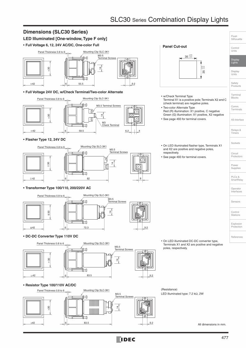
SLC30 Series Combination Display Lights
477
Dimensions (SLC30 Series)LED Illuminated [One-window, Type F only]
• Full Voltage 6, 12, 24V AC/DC, One-color Full
• Full Voltage 24V DC, w/Check Terminal/Two-color Alternate
• Flasher Type 12, 24V DC
• Transformer Type 100/110, 200/220V AC
• DC-DC Converter Type 110V DC
• Resistor Type 100/110V AC/DC
35
35
+0.6–0.4
+0.
6–0
.4
Panel Cut-out
• w/Check Terminal TypeTerminal X1 is a positive pole; Terminals X2 and C (check terminal) are negative poles.
• Two-color Alternate TypeRed (R) illumination: X1 positive, C negativeGreen (G) illumination: X1 positive, X2 negative
• See page 493 for terminal covers.
• On LED illuminated flasher type, Terminals X1 and X2 are positive and negative poles, respectively.
• See page 493 for terminal covers.
• On LED illuminated DC-DC converter type, Terminals X1 and X2 are positive and negative poles, respectively.
(Resistance)
LED illuminated type: 7.2 kΩ, 2W
All dimensions in mm.
9.242
30
55.56
14
Terminal ScrewsM3.5
Panel Thickness 0.8 to 6 Mounting Clip SLC-3K1
42
30
6 59.5
14
M3Check Terminal
6.2 4
Panel Thickness 0.8 to 6 Mounting Clip SLC-3K1
M3.5 Terminal Screws
42
30
6 82
14
8
Panel Thickness 0.8 to 6 Mounting Clip SLC-3K1
Terminal ScrewsM3.5
9.242
30
72.36
14
Terminal ScrewsM3.5
Panel Thickness 0.8 to 6 Mounting Clip SLC-3K1
9.2
14
Panel Thickness 0.8 to 6 Mounting Clip SLC-3K1
42 83.56
30
Terminal ScrewsM3.5
9.242
30
83.56
14
Panel Thickness 0.8 to 6 Mounting Clip SLC-3K1
Terminal ScrewsM3.5

SLC30 Series Combination Display Lights
478
Dimensions (SLC30 Series)Incandescent Illuminated [Side & Rear Views]
Incandescent Illuminated [One-window, Type F only]
• Full Voltage 6, 12, 18, 24V AC/DC, One-color Full
• Transformer Type 100/110, 200/220V AC
• Resistor Type 110V AC/DC
Pan
el T
hick
ness
0.8
to 6
Pan
el T
hick
ness
0.8
to 6
Pan
el T
hick
ness
0.8
to 6
137
306
57.5
306
79.5
306
8
1430
8
30 30
1430
30
9.2
9.230
(Resistance)Incandescent: 2 kΩ, 20W
Terminal Screw M3.5 M3.5 Terminal Screw
M4 Terminal ScrewPower Supply
M4 Terminal ScrewPower Supply
M4 Terminal ScrewPower Supply
M4 Terminal ScrewPower Supply
• Full Voltage Type • 6, 12, 18, 24V AC/DC• One-color full
• Transformer Type• 100/110, 200/220V AC
• Resistor Type• 110V AC/DC
• Terminal cover is available. For dimensions, see page 493.
35+0.6–0.4
Panel Cut-out
35+
0.6
–0.4
All dimensions in mm.
(Resistance)
Incandescent: 2 kΩ, 2W
42
30
57.56
M3.5 Terminal Screw
14
Panel thickness 0.8 to 6 Mounting Clip SLC-3K1
8
42
30
79.56
Panel Thickness 0.8 to 6Mounting Clip SLC-3K1
14
8
M3.5 Terminal Screw
13742
30
69.2
Panel Thickness 0.8 to 6Mounting Clip SLC-3K1
M4 Terminal ScrewPower Supply
M4 Terminal ScrewPower Supply

ControlUnits
Display Lights
DisplayUnits
SafetyProducts
TerminalBlocks
Comm.Terminals
AS-Interface
Relays & Timers
Sockets
Circuit Protectors
Power Supplies
PLCs & SmartRelay
Operator Interfaces
Sensors
Control Stations
Explosion Protection
References
FlushSilhouette
SLC30 Series Combination Display Lights
479
Terminal Connection (LED Illuminated)• For one-color full LED Illuminated with check terminal, DC-DC
converter type, and resistor type, Terminals X1 and X2 are positive and negative poles, respectively.
(Flasher Type Connection Diagram)
• For w/check terminal and two-color alternate type units, terminal X1 is a positive pole; Terminals X2 and C (check terminal) are negative poles.
• Connection for two-color alternate type is as follows.Red (R) — Terminal X1: positive, Terminal C: negativeGreen (G) — Terminal X1: positive, Terminal X2: negative
• For the LED illuminated split-window type (Type C), Terminal X1 is a common terminal. Terminal X2 is a negative pole of upper illumination and Terminal X3 is a negative pole of lower illumination.
Terminal Connection Using Jumpers• For terminal connection of types F, H, L, V, and G (except Type
C), jumpers can be used as shown below.
SLC30 Series
Note 1: fingersafe, spring-up terminals are used in one-color full illuminated type (6, 12, 24V AC/DC, 100/110, 200/220V AC, 110V DC).
Note 2: No jumper is used on resistor type.
• For Type C, jumpers can be used on Terminal X1 only as shown below.
Note: Jumpers cannot be used when using both Type C and fingersafe spring-up terminals.
[Examples of Using Jumpers]LED Illuminated (fingersafe Spring-up Terminal)
Fingersafe, Spring-up Terminal
Other terminals
Arrows indicate access directions for wiring terminals.
LED Module
FlasherCircuit
X1
Positive
NegativeX2
X1
X2
C
(w/Check Terminal Type Connection Diagram)
X1Positive
Negative
Negative
C
X2
LEDModule
Arrows indicate access directions for wiring terminals.
(Two-color alternate Type Connection Diagram)
X1Common
CRed (R)
X2Green (G)
LED Module
Positive
Negative
Negative
X1
X3
X2
Arrows indicate access directions for wiring terminals.
Terminal X1 Terminal X2 Terminal C
LEDIlluminated(Note 2)
Fingersafe, Spring-up
Terminal (Note 1)
SLCN-JP34SLCN-JP35
SLCN-JP34SLCN-JP35 —
Others SLC-JP30 SLC-JP33 SLC-JP32
Incandescent Illuminated SLC-JP30 SLC-JP33 SLC-JP32
Direction• When using Type C only• When using Type C and Two-color alternate
Vertical SLC-JP33Horizontal SLC-JP30
Using one SLCN-JP35 jumperWhen connecting two windows
Using two SLCN-JP35 jumpersWhen connecting three windows
Using one SLCN-JP34 jumperWhen connecting four windows
Jumpers (SLCN-JP34/35) have an orientation.Ensure that jumpers are installed correctly.
Correct Incorrect

SLC30 Series Combination Display Lights
480
Type No. Development (SLC30 Series)
Unit Type (Code)Operating Voltage
(Built-in Lamp) (Code)
LED
Illu
min
ated
LED
Uni
t
Full Voltage Type (A, G, R, W, Y) DD
6V AC/DC ±5% 6
12V AC/DC ±10% 1
24V AC/DC ±10% 2
Full Voltage Type (PW, S) DDA 24V AC/DC ±10% 2
Full Voltage w/Check Terminal Type(A, G, R, W, Y) DHM 24V DC ±10% 2
Full Voltage Two-color Alternate (R/G) DW 24V DC ±10% 2
Full Voltage Flasher Type (A, G, R, W, Y) DF 24V DC ±10% 2
Transformer Type (A, G, R, W, Y) TD100/110V AC ±10% 1
200/220V AC ±10% 2
Transformer Type (PW, S) TDA100/110V AC ±10% 1
200/220V AC ±10% 2
DC-DC Converter Type (A, G, R, W, Y) CD 110V DC (90 to 140V DC) 1
Resistor Type (A, G, R, W, Y) RN 100/110V AC/DC ±10% 1
LED
Lam
p
One-color Full × 2 split window type (Type C)(A, G, R, W, Y)
SX6S/8Base DP
6V AC/DC ±10% (LFTD-6∗) 6
12V AC/DC ±10% (LFTD-1∗) 1
24V AC/DC ±10% (LFTD-2∗) 2
Inca
ndes
cent
Illum
inat
ed
Full Voltage Type BA9S/13Base
DS
5 to 6V AC/DC (LS-6) 6
12 to 18V AC/DC (LS-8) 8
18 to 24V AC/DC (LS-2) (Note) 2
24 to 30V AC/DC (LS-3) 3
TS100/110V AC ±10% (LS-6) 1
200/220V AC ±10% (LS-6) 2
Resistor Type RS 100/110V AC/DC ±10% (LS-8) 1
The following color/voltage selections are also available.
Unit Type (Code)Operating Voltage
(Built-in Lamp) (Code)
LED
Illu
min
ated LE
D U
nit
Full Voltage w/Check Terminal Type(PW, S) DHMA 24V AC/DC ±10% 2
Full Voltage Flasher Type(PW, S) DFA 24V AC/DC ±10% 2
Transformer Type (A, G, R, W, Y) TD115/120V AC ±10% 12
230/240V AC ±10% 24
Transformer Type (PW, S) TDA115/120V AC ±10% 12
230/240V AC ±10% 24
DC-DC Converter Type (PW, S) CDA 110V DC (90 to 140V DC) 1
Resistor Type (PW, S) RNA 100/110V AC/DC ±10% 1
LED
Lam
p
One-color Full × 2 split window type(Type C)(combination of S only) SX6S/8
Base
DPA
6V AC/DC ±5% (LFTD-6S) × 2 6
12V AC/DC ±10% (LFTD-1S) × 2 1
24V AC/DC ±10% (LFTD-2S) × 2 2
One-color Full × 2 split window type (Type C)(combination of S andA, G, R, W, Y)
DPC
6V AC/DC ±5% (LFTD-6∗) 6
12V AC/DC ±10% (LFTD-1∗) 1
24V AC/DC ±10% (LFTD-2∗) 2
Inca
ndes
cent
Illum
inat
ed
Transformer Type BA9S/13Base TS
115V AC ±10% (LS-6) 11
120V AC ±10% (LS-6) 12
230V AC ±10% (LS-6) 23
240V AC ±10% (LS-6) 24
380V AC ±10% (LS-6) 38
400/440V AC ±10% (LS-6) 4
480V AC ±10% (LS-6) 48
Equivalent of Basic Size Windows
Rows Columns
01 01
02 02
03 03
04 04
05 05
06 06
07 07
08 08
09 09
10 10
11
12
13
14
15
16
17
18
19
20
21
22
23
24
25
26
SLC30N – 4 0 50 – DD 2 F B
30 Series When ordering Type H, L, V, G, or C units, enter the equivalents of Type F.
Illumination Face Size (Code)
•Type F30 × 30 mm
F
•Type H30 × 60 mm
H
•Type H(2-way split)30 × 60 mm
A light barrier, clear marking plate, and color screen for 2-way split illumination are supplied.
H2
•Type L30 × 90 mm
L
•Type V60 × 30 mm
V
•Type V60 × 60 mm
G
•Type C(15 × 30 mm) × 2
C
•Type MCombination of types F, H, L, V, G, and C (specify in the ordering sheet)
M
•Type F Spot Illumination30 × 30 mm FST
Illumination Color
•Clear Lens Combination (Code)
Amber AGreen GRed RBlue SWhite WYellow Y•Color Screen Combination(LED only) (Code)
When color display is required at power off, order color screens. For details, see page 501.Amber TAGreen TGRed TRBlue TSWhite TWYellow TY•Gray Lens Combination
(Code)
Amber SAGreen SGRed SRBlue SSWhite SWYellow SY•Type L, V, and G cannot be split-illuminated.
•Use specification sheet when ordering Type M unit or 2-way split illumination type.
•Enter the required number of color screens in ( ).
• Lambda ConverterPure White PWOne-color Full Type F only (except spot illumination type)
Frame Color
Black: B
Example: G (5), R (5), W (10) Specify the color code and the number of windows.–
Note: For longer lamp life, LS-3 (30V rating, 1W) lamps are recommended when using on 24V AC/DC.

ControlUnits
Display Lights
DisplayUnits
SafetyProducts
TerminalBlocks
Comm.Terminals
AS-Interface
Relays & Timers
Sockets
Circuit Protectors
Power Supplies
PLCs & SmartRelay
Operator Interfaces
Sensors
Control Stations
Explosion Protection
References
FlushSilhouette
SLC30 Series Combination Display Lights
481
Ordering Information (SLC30) [Conversion Rate]
1
1
2
3
4
2 3 4 5
Ex. 1
Ex. 2
Ex. 3
Ex. 4
Type F, 20 windows
Type H, 9 windows (Type F equivalent: 3 rows by 6 columns)
Type M, 9 windows (Type F equivalent: 2 rows by 6 columns)
Incandescent illuminated typewhen arrangement of colorscreen is not designated.
LED illuminated unitsin one color.
SLC30N-
Color screen: Type F, 20 windows
Color screen: Type H, 9 windows
Specify the position and each colorcode on the specification sheet.
G(5) + R(5) + S(5) + Y(5) + = 20
G (3) + R(3) + Y (3) = 9
SLC30 Series
04 G(5), R(5), S(5), Y(5)05 F R (20)
R (9)SLC30N-
SLC30 Series
03 G(3), R(3), Y(3)
No entry is required in designations.
No entry is required in designations.
Specify each color code on thespecification sheet.
Specify each color code on thespecification sheet.
No entry is required in designations.06 H
SLC30 Series (Type F, 12 windows)
When ordering a combination of units with different operating voltages, specify Type No. as follows.
Specify the position of the units and each voltage on the specificaiton sheet.
24V AC/DC 100/110V AC 48
Color screen: Type H, 9 windowsR (9) = 9
SLC30N-
SLC30 Series
02 06 M
+ -SLC30N-0304- DD 2 FB(8) TD 1 FB(4) W (12)
Columns
Columns
Rows
Columns
Rows
Rows
1
2
3
4
5
1 2 3 4 5 6R R R R R
G G G G G
Y Y Y Y Y
A A A A A
+ + + + + +
+
+
+
+
Columns
Rows
Columns
Rows
Columns
Rows
Color Code
Color Code
Columns
Rows
Color Code
1
2
3
4
1 2 3 4 5 6R A A
R Y Y
R G G
+ + + + + +
+
+
+
+
7
1
2
3
1 2 3 4 5 6G
W G G
Y
Y
+ + + + + +
+
+
+
7
1
2
3
1 2 3 4 5
+
+
+
DD2
TD1
Color screen: Type F, 20 windowsR (20) = 20
1
1
2
3
2 3 4 5 6
1
1
2
2 3 4 5 6
Ex.Color Code
Color Code
Color Screen Code
Color Screen Code
Ex.
Ex. 5 When ordering a combination of units with diffrent illuminatin colors, specity Type No. as follows.
Specify the position of the unitsand each color code on thespecificaiton sheet.
Example: Full voltage LED illuminated 24V AC/DC, Red (6), Pure White (2)
Columns
Rows
Color Code
SLC30N-0204-DD2FB(6) + DDA2FB(2) - R(6)PW(2)Red Pure White Designation
Red: 6, Pure White: 2
1
2
1 2 3 4 5PW R R R
PW R R R
+ + + +
+
+
+
Type F, 12 windows, Full voltage type
• When more than one color is required for LED.
• When a particular arrangement of color screen is required.
• When color screen is required, specify the color screen code.
• When color screen is required, specify the color screen code.
Transformer Type
When ordering SLC Series Combination Display Lights, use the specification sheet provided on page 509.
•••• Designation Procedure1. Type No.: Refer to Type No. Configuration on page 480.2. Quantity: Enter the required number of identical assemblies.
•••• Counting of WindowsCount the number of windows in the equivalent of Type F (basic size).
•••• Leaf Spring (for one-window type only)Leaf spring for temporary fastening is not attached, and can be supplied free of charge upon request when ordering (Type No. SLD44KVP).
• Type H (horizontal type)
• Type L (horizontal type)
• Type V (vertical type)
• Type G (large type)
• Type C (split-window type)
Type F equivalent: 2 windowsRow (1), Column (2)
Type F equivalent: 3 windowsRow (1), Column (3)
Type F equivalent: 2 windowsRow (2), Column (1)
Type F equivalent: 4 windowsRow (2), Column (2)
Type F equivalent: 1 windowRow (1), Column (1)
[Designation Examples]
Recommended