Contents
Cables pg 3
Thermal Interface pg 4
Screw Kits pg 5
DIN adaptors pg 6
Heatsinks pg 9
Protection Covers pg 11
Fans pg 13
Terminal Adapters pg 14
Varistors pg 18
Temperature Limit Switches pg 20
Solid State RelaysAccessories


Specifications are subject to change without notice (08.10.2015) 3
Solid State RelaysAccessories, CablesTypes RCS..
R-System cableNo. of wiresCable length in cmTermination at one end
Ordering Key RCS 3 -100 -1
Selection Guide
Part No. No. of wires
Cable length (cm) Type Cable size Termination
RCS3-100-1 3 100 UL style 2547 0.14mm² 3-pin socket to mate with RM1E..V..
RCS4-100-1 4 100 UL style 2464 0.14mm² 4-pin socket to mate with RA2A..C
RCS4-400-1 4 400 UL style 2464 0.14mm² 4-pin socket to mate with RA2A..C
RCS5-200-1 5 200 UL style 2464 0.25mm² 5-pin socket to mate with RA..S
4 Specifications are subject to change without notice (08.10.2015)
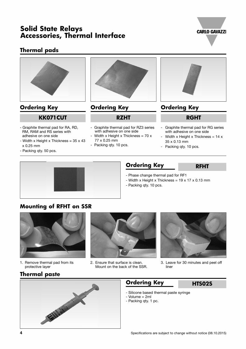
Solid State RelaysAccessories, Thermal Interface
Thermal pads
- Graphite thermal pad for RA, RD, RM, RAM and RS series with adhesive on one side- Width x Height x Thickness = 35 x 43 x 0.25 mm- Packing qty. 50 pcs.
1. Remove thermal pad from its protective layer
2. Ensure that surface is clean. Mount on the back of the SSR.
3. Leave for 30 minutes and peel off liner
Ordering Key
KK071CUT
- Graphite thermal pad for RZ3 series with adhesive on one side- Width x Height x Thickness = 70 x 77 x 0.25 mm- Packing qty. 10 pcs.
Ordering Key
RZHT
- Graphite thermal pad for RG series with adhesive on one side- Width x Height x Thickness = 14 x 35 x 0.13 mm- Packing qty. 10 pcs.
Ordering Key
RGHT
- Phase change thermal pad for RF1- Width x Height x Thickness = 19 x 17 x 0.13 mm- Packing qty. 10 pcs.
Ordering Key
Mounting of RFHT on SSR
RFHT
Thermal paste
- Silicone based thermal paste syringe- Volume = 2ml- Packing qty. 1 pc.
Ordering Key HTS02S

Specifications are subject to change without notice (08.10.2015) 5
Please refer to SSR datasheet and / or heatsink datasheet, as applicable, for reference to the type of screw suitable for mounting a specific SSR model on a specific heatsink
Selection Guide
Part No. Screw size Length Packing qty. Screw head
SRWKITM5X10MM M5 10mm 20 Pozidrive PZ2
SRWKITM4X15MM M4 15mm 20 Philips
SRWKITM5X23MM M5 23mm 20 Torx T20
SRWKITM5X30MM M5 30mm 20 Torx T20
Solid State RelaysAccessories, Screw KitsTypes SRWKIT…
Screw KitScrew sizeScrew length
Ordering Key SRWKIT M5 X 10MM

6 Specifications are subject to change without notice (08.10.2015)
DIN rail adaptor module for mounting RP series SSRs on DINrail. The RPM1 is intended for max. operational voltage of250V, whilst the RPM2 can be used up to 600V.
The RP SSR is not included. Suffix 'M1' or 'M2' is added to theSSR part no. for a factory mounted solution.
Note that when the RP..10 is mounted on DIN rail (verticalmounting), a derating factor has to be applied.
Selection Guide
Part No. Description Packing qty.
RPM1 250V module with LED 1
RPM1V 250V module with LED + varistor across output terminals 1
RPM1P 250V module with pins for easy removal of RP unit 1
RPM1PD 250V module with pins for easy removal of RP unit + LED 1
RPM2 600V module with LED 2
Solid State RelaysAccessories, DIN Adaptors
RP DIN rail adaptor moduleModule sizeOptions
Ordering Key RPM 1 -
DIN Adaptors for PCB SSRs
RPM1
RPM2Dimensions in mm including SSR
Dimensions in mm including SSR

Specifications are subject to change without notice (08.10.2015) 7
DIN Adaptors
Housing material PA, green, UL94 V0Weight RPM1 approx. 15g
RPM2 approx. 20gTerminal screws M3Terminal cable size max. (stranded) 1.5mm2
Mounting torque max. 0.5 NmOperating temperature -20˚ to + 70˚C
[-4 to +158˚F]Storage temperature -40˚ to + 100˚C
[-40˚ to +212˚F]DIN rail guide DIN EN 50022, 50035
Housing Specifications
DIN rail adaptor module for mounting the 1-phase SSR seriesRA, RD, RM, RS and RAM directly on DIN rail.
Suffix H8 added to SSR part no. refers to factory mounted DINclip. Conditions apply. Please ask your Sales representativefor further details.
Ordering Key RHS00
DIN Adaptor for 1-phase SSRs
44
2 x M4
13.581
65 50
Dimensions in mm
Material Electroplated steel

8 Specifications are subject to change without notice (08.10.2015)
DIN Adaptors
DIN rail adaptor module for mounting the RGS series on DINrail.
This adaptor integrates an aluminium plate which allows theRGS with mounted RGS1DIN to be used for load current ofminimum 10AAC @ 40°C. Refer to RGS datasheet for derat-ing characteristics.
Ordering Key RGS1DIN
DIN Adaptor for RGS SSRs
9.29.5
106
98 82 47.5
17.85
Dimensions in mm
Installation Instructions Dimensions
Mounting Instructions
Thermal Pad
provided with
RGS1SDINRGS Solid State Relay
2xscrews + washer M5x23mm, Torx T25
(provided with RGS1DIN)
Max. mounting torque: 1.5Nm

Specifications are subject to change without notice (08.10.2015) 9
Ordering Key RHS..
DIN mount heatsinks
Heatsink reference Mounted fan Thermal resistance
Overall dimensionsnot including SSRWidth x Height xDepth (mm)
Max. number of SSRs per series per heatsink
RA..RD..RM1..RAM1..RS1..
RGS1.. RGS1S..E. RGS1S..U. RGS1P..E RZ3..
RHS00 - 12.3 °C/W ( >10W) 44 x 82 x 16 1 - - - - -
RHS300 - 5.40 °C/W ( >30W) 105 x 82 x 20 - - - - - 1
RHS37A - 4.00 °C/W ( >20W) 18 x 110 x 52 - 1 1 - - -
RHS10015 - 4.00 °C/W ( >30W) 100 x 82 x 29 2 - - - - -
RHS100, RHS100D - 3.10 °C/W ( >25W) 44 x 82 x 48 1 - - - - -
RHS45C, RHS45CD - 2.20 °C/W ( >45W) 45 x 103 x 55 1 - - - - -
RHS52A - 2.00 °C/W ( >45W) 22.5 x 110 x 90 - 1 1 - - -
RHS45B, RHS45BD - 1.85 °C/W ( >50W) 45 x 103 x 80 1 - - - - -
RHS540, RHS540D - 1.85 °C/W ( >60W) 54 x 110 x 51 1 3 1 1 1 -
RHS542, RHS542D - 1.85 °C/W ( >60W) 54 x 110 x 51 - 2 2 - 1 -
RHS703, RHS703D - 1.10 °C/W ( >60W) 72 x 110 x 75 1 3 2 2 1 -
RHS90A, RHS90AD - 0.97 °C/W ( >60W) 90 x 103 x 80 1 - - - - -
RHS301, RHS301D - 0.82 °C/W ( >80W) 119 x 82 x 94 2 - - - - 1
RHS112A, RHS112AD - 0.76 °C/W ( >100W) 112 x 103 x 80 2 - - - - 1
RHS11267DIND - 0.54 °C/W ( >150W) 119 x 125 x 94 2 3 3 2 2 1
RHS540F40-24 24VDC 0.65 °C/W 54 x 135 x 51 1 3 1 1 1 -
RHS542F40-24 24VDC 0.65 °C/W 54 x 135 x 51 - 2 2 - 1 -
RHS703F60-24 24VDC 0.37 °C/W 72 x 141 x 75 1 3 2 2 1 -
RHS703F60-230 220-240VAC 0.37 °C/W 72 x 141 x 75 1 3 2 2 1 -
RHS112AF60-24 24VDC 0.35 °C/W 112 x 120 x 80 2 - - - - 1
RHS112AF60-230 220-240VAC 0.35 °C/W 112 x 120 x 80 2 - - - - 1
RHS301F115C 115VAC 0.28 °C/W 124 x 146 x 122 2 - - - - 1
RHS301F230C 220-240VAC 0.28 °C/W 124 x 146 x 122 2 - - - - 1
RHS28009F80-24P 24VDC 0.12 °C/W 280 x 87 x 122 4 9 9 4 4 -
RHS28011F80-24P 24VDC 0.12 °C/W 280 x 87 x 122 3 11 6 5 - -
The tables below give an overview of the range of CarloGavazzi heatsinks. For specific details refer to the individualdatasheet of each heatsink model.
An online Heatsink Selector Tool available at www.product-selection.net indicates the most suitable heatsink for a specif-ic application.
Solid State RelaysAccessories, HeatsinksTypes RHS..

10 Specifications are subject to change without notice (08.10.2015)
Heatsinks
Heatsink reference
Mountedfan
Thermal resistance
Overall dimensionsnot including SSRWidth x Height x Depth (mm)
Max. number of SSRs per series per heatsink
RF1..
RA..RD..RM1..RAM1..RS1..
RGS1.. RGS1S..E. RGS1S..U. RGS1P..E RZ3..
RHS38ARFD - 2.85 °C/W ( >40W) 46 x 76 x 33 1 - - - - - -
RHS10025D - 1.85 °C/W ( >60W) 100 x 100 x 25 - 1 3 2 1 1 -
RHS16225D - 1.30 °C/W ( >90W) 162 x 100 x 25 - 3 3 3 3 2 1
RHS16225LD - 0.84 °C/W ( >120W) 162 x 250 x 25 - 3 3 3 3 2 1
RHS11267D - 0.54 °C/W ( >150W) 112 x 125 x 67 - 1 3 2 2 1 -
RHS30040D - 0.40 °C/W ( >180W) 300 x 200 x 40 - 8 12 12 5 6 -
Heatsink reference
Mountedfan
Thermal resistance
Overall dimensionsnot including SSRWidth x Height x Depth (mm)
Max. number of SSRs per series per heatsink
RF1..
RA..RD..RM1..RAM1..RS1..
RGS1.. RGS1S..E. RGS1S..U. RGS1P..E RZ3..
RHS5050D - 3.50 °C/W ( >25W) 80 x 50 x 51 - 1 - - - - -
RHS5050RFD - 3.50 °C/W ( >25W) 80 x 50 x 51 1 - - - - - -
RHS38AD - 2.85 °C/W ( >40W) 46 x 76 x 33 - 1 - - - - -
RHS38ARFD - 2.85 °C/W ( >40W) 46 x 76 x 33 1 - - - - - -
RHS10025D - 1.85 °C/W ( >60W) 100 x 100 x 25 - 1 3 2 1 1 -
RHS5840D - 1.80 °C/W ( >60W) 81 x 100 x 40 - 1 3 2 1 1 -
RHS10067D - 1.70 °C/W ( >20W) 121 x 76 x 67 - 1 - - - - -
RHS16225D - 1.30 °C/W ( >90W) 162 x 100 x 25 - 3 3 3 3 2 1
RHS10067LD - 0.88 °C/W ( >80W) 121 x 140 x 67 - 2 2 - - 1 -
RHS16225LD - 0.84 °C/W ( >120W) 162 x 250 x 25 - 3 3 3 3 2 1
RHS320 - 0.40 °C/W ( >120W) 240 x 100 x 93 - 3 3 3 3 3 1
Thru wall mount heatsinks
Panel mount heatsinks

Specifications are subject to change without notice (08.10.2015) 11
Solid State RelaysAccessories, Protection Covers
Ordering Key
Tamper proof accessory kit for RGS1P, RGC1P series containing:- x5 transparent covers- x5 secureness ties
RGTMP
Installation
1: Clip hook of the transparent cover tothe bottom loop of the RGx1P controlmodule 2: Close the cover by clipping to the top
loop of the RGx1P control module
3: Secure with provided tie

12 Specifications are subject to change without notice (08.10.2015)
Protection Covers
- IP20 touch protection cover for RA & RD series - Packing qty. 25 pcs.
Ordering Key BBR
- IP20 touch protection cover for RM, RS and RAM series - Packing qty. 20 pcs.
Ordering Key RMIP20
- IP20 touch protection cover for RA..S series - Packing qty. 25 pcs.
Ordering Key BBR-S
67
45
12
27,5
67
45
12
27,5
Dimensions in mm
67
45
12
27,5
67
45
12
27,5
Dimensions in mmBBR BBR-S
Dimensions in mm
44.8
57.6
8.2
T1L1
A2 (-) A1(+)

Specifications are subject to change without notice (08.10.2015) 13
Ordering Key RHSF..
Fans for mounting to heatsinks RHS45C, RHS45B, RHS90A,RHS112A, RHS540, RHS542, RHS703, RHS301 for higherthermal resistance.
Assemblies with pre mounted fans are also available. Refer toHeatsinks datasheet for further details.
Solid State RelaysAccessories, Fans
Selection Guide
Part No. Size Width x Height x Depth (mm) Voltage rating Power
consumption Suitable for mounting to heatsink
RHSF40-24 40 x 40 x 20 24 VDC 0.92 Watts RHS45C, RHS45B, RHS540, RHS542
RHSF60-24 60 x 60 x 20 24 VDC 1.8 Watts RHS90A, RHS112A, RHS703
RHSF60-230 60 x 60 x 20 220 - 240 VAC,50/60Hz 4.1 / 4.4 Watts RHS90A, RHS112A, RHS703
RHS301F115 120 x 120 x 38 (plus bracket)
115 VAC50/60Hz 20 / 18 Watts RHS301
RHS301F230 120 x 120 x 38 (plus bracket)
220 - 240 VAC,50/60Hz 20 / 19 Watts RHS301
14 Specifications are subject to change without notice (08.10.2015)
RM625FK Dimensions in mm
RM635FK Dimensions in mm
47
27
28,5
RM635FKP Dimensions in mm
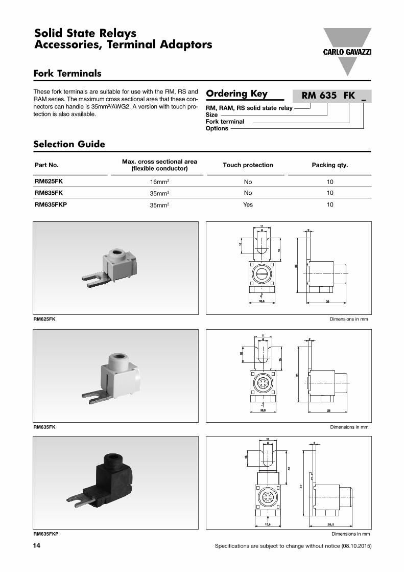
Solid State RelaysAccessories, Terminal Adaptors
These fork terminals are suitable for use with the RM, RS andRAM series. The maximum cross sectional area that these con-nectors can handle is 35mm²/AWG2. A version with touch pro-tection is also available.
Fork Terminals
Ordering KeyRM, RAM, RS solid state relaySizeFork terminalOptions
RM 635 FK _
Selection Guide
Part No. Max. cross sectional area (flexible conductor) Touch protection Packing qty.
RM625FK 16mm2 No 10
RM635FK 35mm2 No 10
RM635FKP 35mm2 Yes 10

Specifications are subject to change without notice (08.10.2015) 15
Terminal Adaptors
FASTON tabs for screw mounting on RM, RS, RAM series.Tabs are tin plated brass with dimensions according toDIN46342 part 1
FASTON Terminals
Ordering KeyRM, RAM, RS solid state relayTab sizeTab orientation
RM 48 F4
Selection Guide
Part No. Tab size Tab orientation Packing qty.
RM48F4 4.8 x 0.8mm for input Angled 45° 20
RM48F0 4.8 x 0.8mm for input Flat 0° 20
RM63F4 6.3 x 0.8mm for output Angled 45° 20
RM63F0 6.3 x 0.8mm for output Flat 0° 20
Housing RM625FK, RM635FK Cycoloy UL94 V0RM635FKP Latamid UL94 V0
Connection lug CuZn37 with surface Zn4ymcA
Max. fastening torque 2Nm (17.7 lb-in)Wire acceptance
Solid Cu conductor RM635FK. 6 - 50mm² (AWG 10 - 1)RM625FK 6 - 25mm² (AWG 10 - 4)
Flexible Cu conductor RM635FK. 6 - 35mm² (AWG 10 - 3)RM625FK 6 - 16mm² (AWG 10 - 6)
Connection diameter RM635FK. 10mmRM625FK 6.5mm
Max. handling current RM635FK. 100 A
General Specifications

16 Specifications are subject to change without notice (08.10.2015)
Terminal Adaptors
Hex tin plated brass spacer M3x12mm for mounting on inputterminals of RM, RS and RAM series to allow for mounting ofPCB on top of SSR
Hex Spacers
Ordering Key
- Dimensions M3 x 12mm- Packing qty. 20 pcs.
RMSP03
Plug Terminals
Ordering Key
- Spring loaded plug terminal for RG series- 2 pole, 1x 0.2-2.5mm² (24 - 12 AWG)- Packing qty. 10 pcs.
RGM25
Ordering Key
- Box clamp plug terminal for RGCM series- 3 way 2 pole, 1x 0.2-2.5mm² (24 - 12 AWG)- Packing qty. 10 pcs.
RG3G25

Specifications are subject to change without notice (08.10.2015) 17
Terminal Adaptors
This plastic adaptor can be fitted to the RGCM housing cover tofacilitate mounting of overload protection relays. This adaptor iscompatible with:
Manufactuers Series ExampleABB TA TA25DU-8.5Siemens 3RU11 3RU1126-1FB0
Packing qty. 5 pcs.
Motor Overload Relay Adaptor
Ordering Key REC3ADAPTOR

18 Specifications are subject to change without notice (08.10.2015)
Mains Uc * Carlo Gavazzi** Epcos AVX Nippon ACPA/ Chemi-Con Song Long
• Transient protection devices for Solid State Relays
Product Description
A metal oxide varistor (MOV)is a voltage dependent resis-tor with a symmetrical V/Icharacteristics curve whoseresistance decreases withincreasing voltage.Varistors are ideally suited forprotecting sensitive elec tron iccircuits and components (po -w er sem i con duc tors) against
voltage transients caused ei -ther by the mains or by otherap pli ca tion parts. Connectedin parallel with the electronicdevice that is to be guarded,they form a low resistanceshunt when voltage increasesand thus prevent any furtherV/I in the over voltage
Ordering Key
Solid State RelaysAccessories, VaristorsType RV
Solid State RelayVaristorVaristor voltage
3-phase mains without neutral
Type Selection
230 V 710 RV 02 SIOV-S20K275 VF20M10431K TND 20V-431 431KD20400 V 1120 RV 04 SIOV-S20K420 VF20M10681K TND 20V-681 681KD20480 V 1355 RV 05 SIOV-S20K510 VF20M10821K TND 20V-821 821KD20600 V 1650 RV 06 SIOV-S20K625 VF20M10102K TND20V-102 102KD20660 V 1815 RV 07 SIOV-S20K680 - TND20V-112 112KD20
Mains Uc * Carlo Gavazzi** Epcos AVX Nippon ACPA/ Chemi-Con Song Long
1-phase and 3-phase mains with neutral
* Uc @ 100 Ap (SIOV-S20K...)** Pack of 10 pieces
* Uc @ 100 Ap (SIOV-S20K...)** Pack of 10 pieces
120/240 710 RV 02 SIOV-S20K275 VF20M10431K TND20V-431 431KD20230/400 710 RV 02 SIOV-S20K275 VF20M10431K TND20V-431 431KD20400/690 1120 RV 04 SIOV-S20K420 VF20M10681K TND20V-681 681KD20
RV 04

Specifications are subject to change without notice (08.10.2015) 19
Varistors
Wiring Diagrams
1-phase
Mains without neutral
3-phase
2-phase
Mains with neutral

20 Specifications are subject to change without notice (08.10.2015)
Temperature limit switch for overheat protection of small assemblies.
Product DescriptionThe temperature limit switch isa readily available accessory.It is a thermostat especiallydesigned for overheat protec-tion for small assemblies.
The thermal response is excel-lent due to its miniaturizedhousing. It becomes an effec-tive thermal cutout due to thefact that this limit switch canbe fitted close to the heatsinkof the relay.
When connected serial withthe control voltage, the TLSwill switch off the relay assoon as the operating temper-ature of the switch is reached.The relay will be activated
Ordering KeyThermostat typeSwitch temperature
again when the temperaturedrops (approx. 30°C) belowits cutout value.
In the RZ3 relay, the TLS canbe connected to two free (in-ternally non-connected) termi-nals (B1/B2).
Thermal compound must beadded when inserting the TLS(to guarantee a fast thermalresponse).
The heatsink selection charts(load current versus ambienttemperature) for RSO typesprovide information aboutwhich thermal switch to use.
Switch temperature
UP 62-70 70°C (158°F)UP 62-80 80°C (176°F)UP 62-90 90°C (194°F)
Type Selection
Installation
The UP 62 - .. is mountedin one of the two slots ofthe 3-phase SSR housing.
All dimensions in mm
UP 62 - 90
Solid State RelaysAccessories, Temperature Limit SwitchesType UP 62 - ..
Recommended


![Switching Relays & Accessories - argocontrols.com · . PN 240004977 REV. [01/07/2020] Switching Relays & Accessories. Easy, Economical Zoning with Circulators. The Difference is in](https://img.pdfslide.net/doc/110x75/5f5e46bccdd494174060666a/switching-relays-accessories-pn-240004977-rev-01072020-switching.jpg)