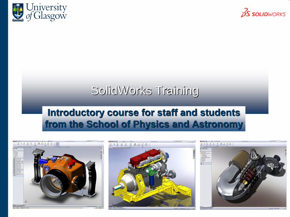
SolidWorks Training
Introductory course for staff and students
from the School of Physics and Astronomy
SolidWorks Training
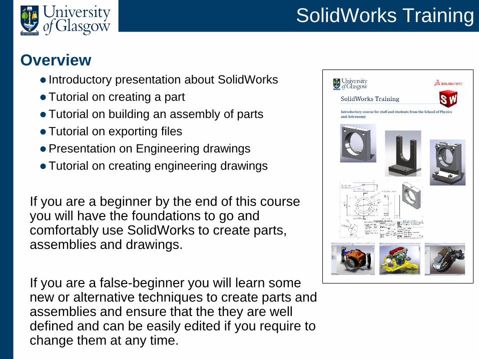
Overview Introductory presentation about SolidWorks
Tutorial on creating a part
Tutorial on building an assembly of parts
Tutorial on exporting files
Presentation on Engineering drawings
Tutorial on creating engineering drawings
If you are a beginner by the end of this course you will have the foundations to go and comfortably use SolidWorks to create parts, assemblies and drawings.
If you are a false-beginner you will learn some new or alternative techniques to create parts and assemblies and ensure that the they are well defined and can be easily edited if you require to change them at any time.
SolidWorks Training
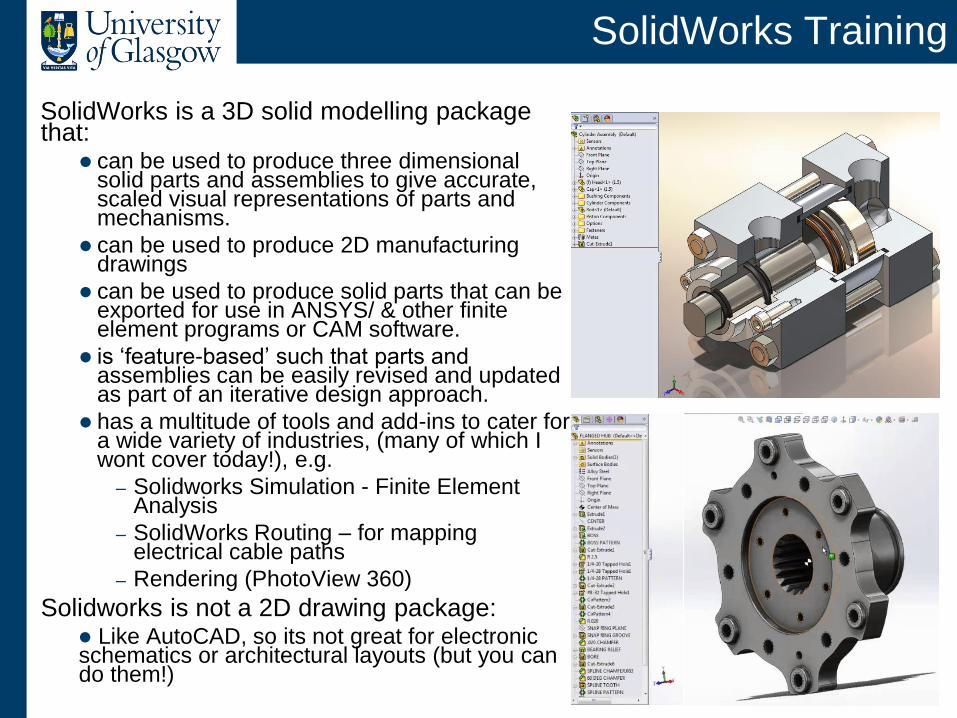
SolidWorks is a 3D solid modelling package that:
can be used to produce three dimensional solid parts and assemblies to give accurate, scaled visual representations of parts and mechanisms.
can be used to produce 2D manufacturing drawings
can be used to produce solid parts that can be exported for use in ANSYS/ & other finite element programs or CAM software.
is ‘feature-based’ such that parts and assemblies can be easily revised and updated as part of an iterative design approach.
has a multitude of tools and add-ins to cater for a wide variety of industries, (many of which I wont cover today!), e.g.
– Solidworks Simulation - Finite Element Analysis
– SolidWorks Routing – for mapping electrical cable paths
– Rendering (PhotoView 360)
Solidworks is not a 2D drawing package: Like AutoCAD, so its not great for electronic schematics or architectural layouts (but you can do them!)
SolidWorks Training
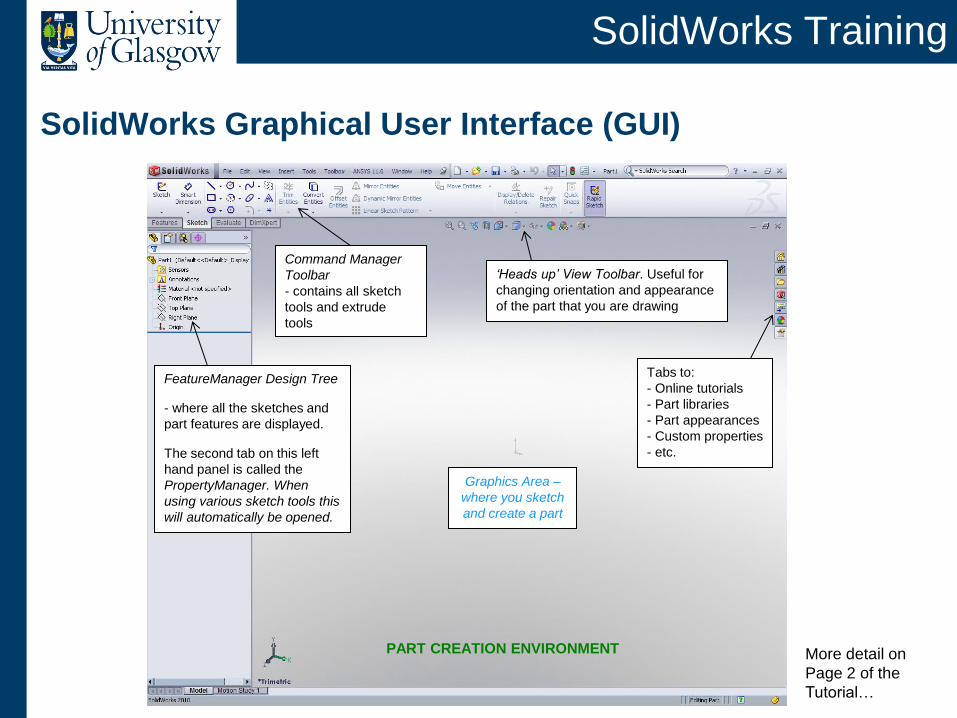
SolidWorks Graphical User Interface (GUI)
Command Manager
Toolbar
- contains all sketch
tools and extrude
tools
‘Heads up’ View Toolbar. Useful for
changing orientation and appearance
of the part that you are drawing
Tabs to:
- Online tutorials
- Part libraries
- Part appearances
- Custom properties
- etc.
Graphics Area –
where you sketch
and create a part
PART CREATION ENVIRONMENT
FeatureManager Design Tree
- where all the sketches and
part features are displayed.
The second tab on this left
hand panel is called the
PropertyManager. When
using various sketch tools this
will automatically be opened.
More detail on
Page 2 of the
Tutorial…
SolidWorks Training
Using SolidWorks
The SW interface is designed for use in Windows and has similarities
to the interface in many Microsoft products.
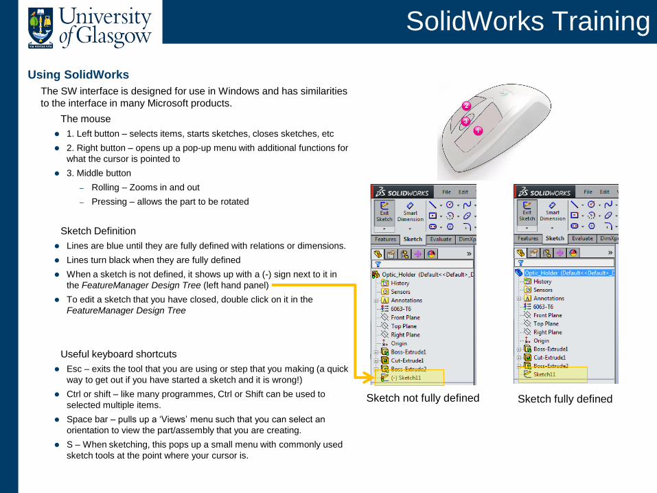
The mouse
1. Left button – selects items, starts sketches, closes sketches, etc
2. Right button – opens up a pop-up menu with additional functions for
what the cursor is pointed to
3. Middle button
– Rolling – Zooms in and out
– Pressing – allows the part to be rotated
Sketch Definition
Lines are blue until they are fully defined with relations or dimensions.
Lines turn black when they are fully defined
When a sketch is not defined, it shows up with a (-) sign next to it in
the FeatureManager Design Tree (left hand panel)
To edit a sketch that you have closed, double click on it in the
FeatureManager Design Tree
Useful keyboard shortcuts
Esc – exits the tool that you are using or step that you making (a quick
way to get out if you have started a sketch and it is wrong!)
Ctrl or shift – like many programmes, Ctrl or Shift can be used to
selected multiple items.
Space bar – pulls up a ‘Views’ menu such that you can select an
orientation to view the part/assembly that you are creating.
S – When sketching, this pops up a small menu with commonly used
sketch tools at the point where your cursor is.
Sketch not fully defined Sketch fully defined
SolidWorks Training
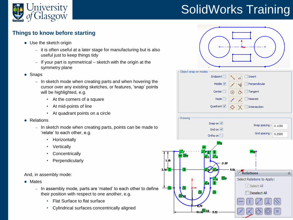
Things to know before starting
Use the sketch origin
– it is often useful at a later stage for manufacturing but is also
useful just to keep things tidy
– If your part is symmetrical – sketch with the origin at the
symmetry plane
Snaps
– In sketch mode when creating parts and when hovering the
cursor over any existing sketches, or features, ‘snap’ points
will be highlighted, e.g.
• At the corners of a square
• At mid-points of line
• At quadrant points on a circle
Relations
– In sketch mode when creating parts, points can be made to
‘relate’ to each other, e.g.
• Horizontally
• Vertically
• Concentrically
• Perpendicularly
And, in assembly mode:
Mates
– In assembly mode, parts are ‘mated’ to each other to define
their position with respect to one another, e.g.
• Flat Surface to flat surface
• Cylindrical surfaces concentrically aligned
SolidWorks Training
Last of all, before we get started…
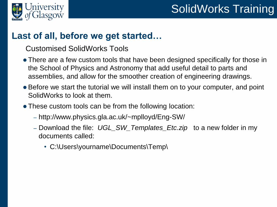
Customised SolidWorks Tools
There are a few custom tools that have been designed specifically for those in
the School of Physics and Astronomy that add useful detail to parts and
assemblies, and allow for the smoother creation of engineering drawings.
Before we start the tutorial we will install them on to your computer, and point
SolidWorks to look at them.
These custom tools can be from the following location:
– http://www.physics.gla.ac.uk/~mplloyd/Eng-SW/
– Download the file: UGL_SW_Templates_Etc.zip to a new folder in my
documents called:
• C:\Users\yourname\Documents\Temp\
Tutorial One – Parts
Tutorial Two – Assemblies
Tutorial Three – Exporting Parts or assemblies for use in
other CAD packages/FEA/CAM
SolidWorks Training
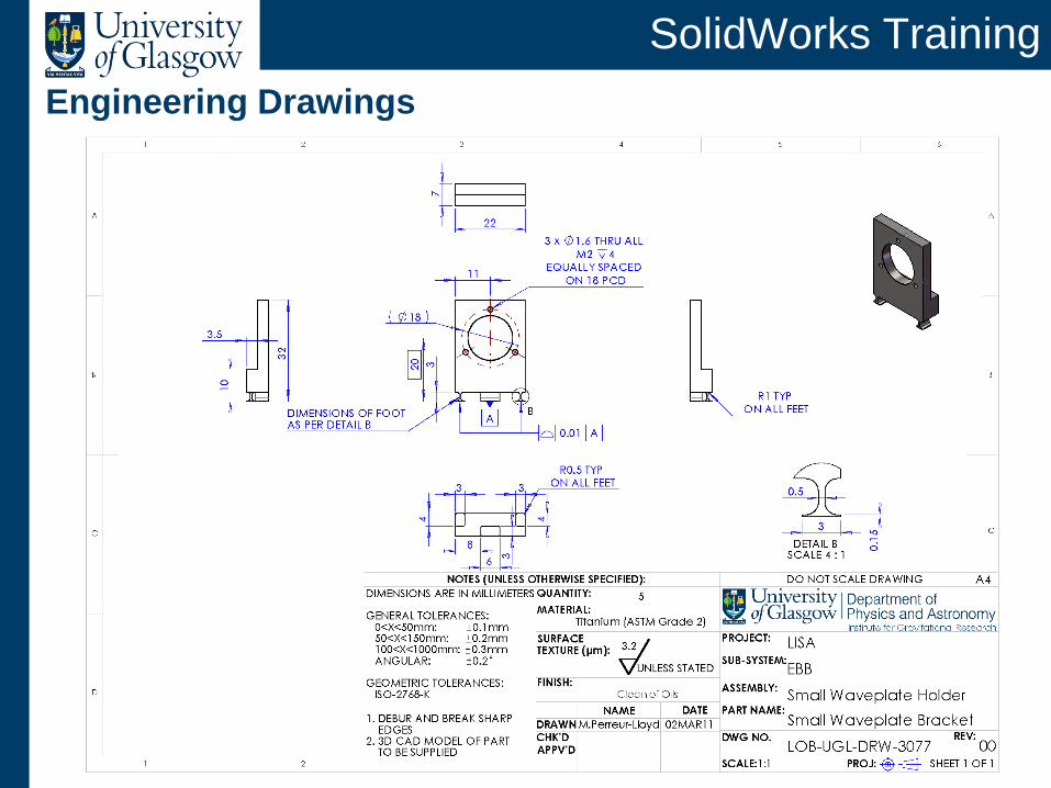
Engineering Drawings
SolidWorks Training
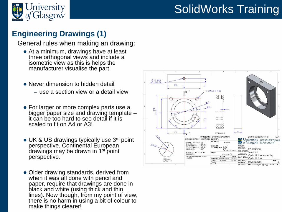
Engineering Drawings (1) General rules when making an drawing:
At a minimum, drawings have at least three orthogonal views and include a isometric view as this is helps the manufacturer visualise the part.
Never dimension to hidden detail
– use a section view or a detail view
For larger or more complex parts use a bigger paper size and drawing template – it can be too hard to see detail if it is scaled to fit on A4 or A3!
UK & US drawings typically use 3rd point perspective. Continental European drawings may be drawn in 1st point perspective.
Older drawing standards, derived from when it was all done with pencil and paper, require that drawings are done in black and white (using thick and thin lines). Now though, from my point of view, there is no harm in using a bit of colour to make things clearer!
SolidWorks Training
Engineering Drawings (2)
General rules continued…
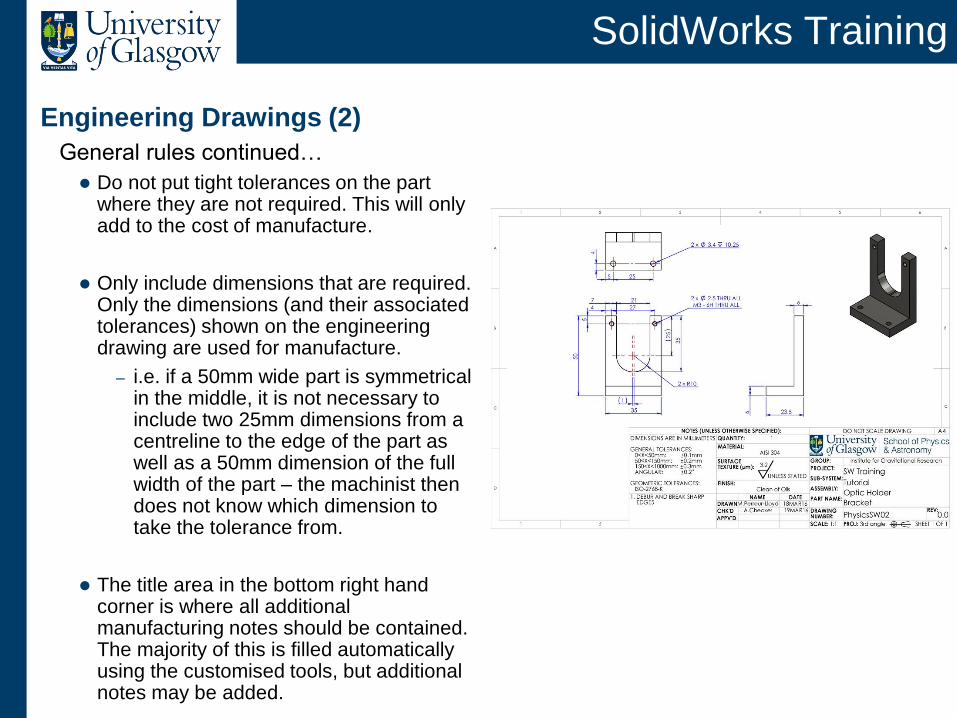
Do not put tight tolerances on the part where they are not required. This will only add to the cost of manufacture.
Only include dimensions that are required. Only the dimensions (and their associated tolerances) shown on the engineering drawing are used for manufacture.
– i.e. if a 50mm wide part is symmetrical in the middle, it is not necessary to include two 25mm dimensions from a centreline to the edge of the part as well as a 50mm dimension of the full width of the part – the machinist then does not know which dimension to take the tolerance from.
The title area in the bottom right hand corner is where all additional manufacturing notes should be contained. The majority of this is filled automatically using the customised tools, but additional notes may be added.
SolidWorks Training
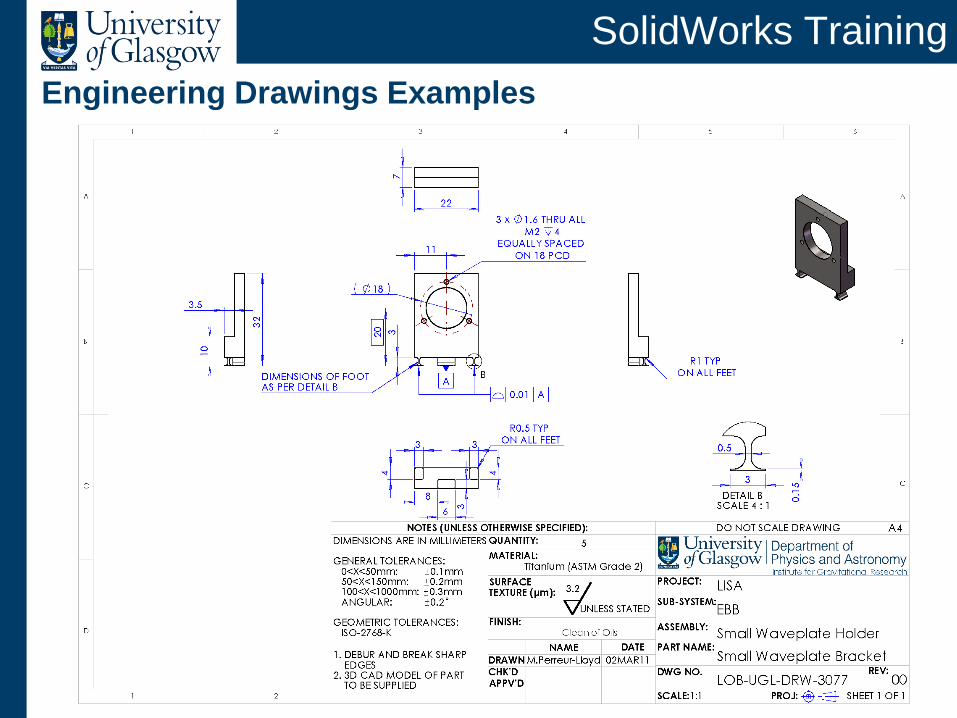
Engineering Drawings Examples
SolidWorks Training
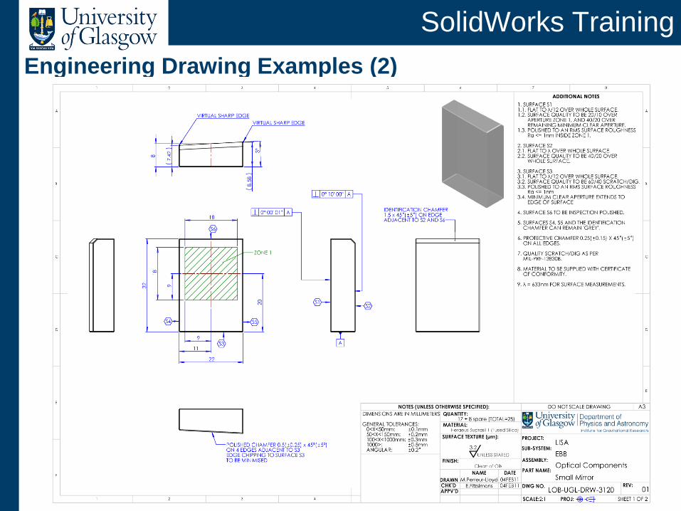
Engineering Drawing Examples (2)
SolidWorks Training
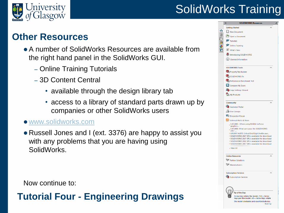
Other Resources
A number of SolidWorks Resources are available from
the right hand panel in the SolidWorks GUI.
– Online Training Tutorials
– 3D Content Central
• available through the design library tab
• access to a library of standard parts drawn up by
companies or other SolidWorks users
www.solidworks.com
Russell Jones and I (ext. 3376) are happy to assist you
with any problems that you are having using
SolidWorks.
Now continue to:
Tutorial Four - Engineering Drawings
Recommended