SPECIALIZING IN PRECISIONHORIZONTAL BORING MILLS
www.fermatmachinery.com

WRF 150 CNC for Pöytyän Koneistuspalvelu, Finland
Parameters: x=14700 mm/579”|y=6000 mm/236” | z= 1200/47" | w=1000mm/39” | v=5500mm/217”; Heidenhain iTNC 530 Control System
COMPANY INFO Fermat Fast Facts 04About Fermat 06Fermat Production Plants 08Customer Service 10
TABLE TYPE HORIZONTAL BORING MILLS 12WFT 13 CNC 14WRFT 130 CNC 18WFC 13 CNC 22WFC 10 CNC 24
FLOOR TYPE HORIZONTAL BORING MILLS 26WRF Series 28WRF 130 CNC Portable 31WF 13 CNC 32
OTHER PRODUCTS
MILLING MACHINES FGU (RT) CNC 36WRF MILL CNC 38
GRINDING MACHINES BUC E 63 CNC 40BUB E 50 CNC 40
MACHINE COMPONENTS Headstock 42Rotary Table 43Control Systems 44Electrical | Hydraulic | Lubrication Units 46Other Components 47
SPECIAL ACCESSORIES Automatic Pallet Changer System APC 48Automatic Tool Changer ATC | Robots 49Milling Heads, Facing Heads 50Platforms | Workspace Enclosures 54Other Accessories 56
REFERENCE MACHINES 58
Content:

5 4
2nd
8 100+
535Number of employees largest consumer of Heidenhain and
Fanuc in local market
Annual production/sold machinesBranches in Czech Republic
1902Oldest member of FERMAT GroupAnnual sales in 2011
Fermat Fast Facts Web page
Search our products in 10 different languages.
www.fermatmachinery.com
Our website is a key tool to help us grow closer to
our customers anywhere around the world.
Micron (1 µm) has the most accurate production machine from our
machining shop
1
57
Football playgrounds would fit in floor space of FERMAT Production facilities
5
mil.€
CO
MPA
NY
INFO

7 6
About FermatFERMAT Company is a renowned Czech manufacturer of ma-chine tools with a focus on Horizontal Boring and Milling ma-chines. The history of the oldest Fermat member dates back to 1902 when Mr. Frantisek Wawerka started his first business and built a new factory specialized in the production of Lathes & Drilling machines. Over a one hundred year long tradition in machine tool production places the company among domi-nant Machine Tool Manufacturers in the European as well as the Worldwide market. Fermat horizontal boring machines allow CNC machining with a spindle diameter from 100 to 170 mm | 3.94"-6.69". Thanks to the modular production system we supply our customers with reliable and flexible machines. Our components and accesso-ries are produced directly in Fermat or delivered by the world--renowned companies (FH, SKF, Thyssen Krupp, Schneeberger, Siemens, etc.). This kind of production provides our customers with a better service, fast delivery time and high quality.
Industrial ApplicabilityFERMAT horizontal boring mills are used mainly in heavy ma-chinery such as construction, marine, aircraft or defense indu-stry as well as in mining, oil-gas or railway sector. Various parts such as crane jibs, gantry cranes or pedastals, winches, frames, storage tanks etc. make example of common workpieces of horizontal boring mills.By nature of their versatility, rigid design and accuracy Fermat Boring Mills are suitable for a wide range of Industry including Heavy Construction Equipment, Forest, Oil & Gas, Vessels, Mold & Die, Turbine and related Power Generation and Aerospace, just to mention a few.Special requirements such as Windmill Hub machining and Portable applications are a specialty for Fermat.
FERMAT Number of Employees
Production Fermat‘s annual production is now over 100 machines. Thanks to this number we do guarantee customers reliable, con-venient and most standardized design table or floor boring machines with fast delivery. The modular system of produc-tion, experienced engineers and technicians allows Fermat to supply machines according to our customer’s needs whether in standard or special design. This Flexibility and inovation is our guarantee for future success!
Production facilitiesFERMAT occupies 29 500m2 (317 535 sq ft) production and assembly halls. The most important centers are situated in Prague and Brno (Prague 5300 m2/57 049 sq ft/ Brno 4800 + 3 600m2 / 38750 sq ft). The company sales soared despite the recent economic crisis. In the same period Fermat acquired several traditional manufacturers like Pressl Company in Pil-sen and Strojtos Lipnik to increase the production facilities.
Worldwide sales and distributionBased in the “heart” of Europe, Fermat is one of the leading suppliers of machine tools - horizontal boring machines (both table/floor type machines) in Central Europe. The company celebrated achievements not only in European markets, but also in Canada, USA, Russia, India, China and South America, exporting to more than 40 countries worldwide. Fermat‘s con-stantly growing and increasing its market share and partici-pates at main International Fairs around the world including EMO- the leading International Trade Fair for the machine tool industry and IMTS - the largest machine tool exhibition for the North American market.
FERMAT Total Turnover
60 mil. €
20092008
30 mil. €
10 mil. €
40 mil. €
20 mil. €
50 mil. €
2010 2011
35 mil. €36 mil. €
49 mil. €57 mil. €
0
300
400
150
50
200
100
250
350
450
500500 535
2008 2009 2010 2011 2012
339 340
449
0Lipnik Plant 1920
Brno Plant 2006
Fermat Assembly Shop
Prague Machining Shop
CO
MPA
NY
INFO

9 8
ROKYCANY
BRNO
LIBERECLIPNIK
EU
Fermat Production PlantsCzech Republic
AUSTRIA
VIENNA
ROME
BRNO
PARIS
PRAGUE
MUNICH
FRANKFURT
GERMANY POLAND
SLOVAKIA
Brno-Vienna 2hrsPrague-Liberec 1hrsPrague-Rokycany 1hrs
Brno-Lipnik 1hrs
Prague-Brno 2hrsPRAGUE
CO
MPA
NY
INFO
8
11 10
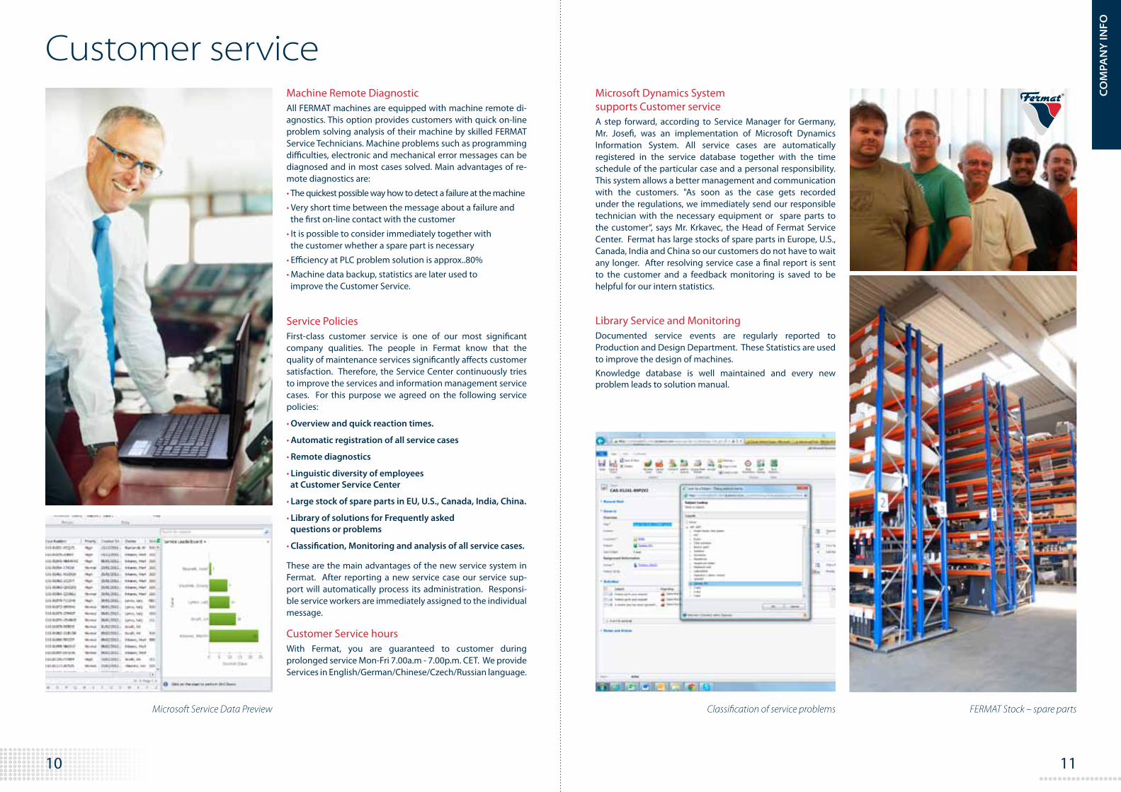
Service Policies First-class customer service is one of our most significant company qualities. The people in Fermat know that the quality of maintenance services significantly affects customer satisfaction. Therefore, the Service Center continuously tries to improve the services and information management service cases. For this purpose we agreed on the following service policies:
• Overview and quick reaction times.
• Automatic registration of all service cases
• Remote diagnostics
• Linguistic diversity of employees at Customer Service Center
• Large stock of spare parts in EU, U.S., Canada, India, China.
• Library of solutions for Frequently asked questions or problems
• Classification, Monitoring and analysis of all service cases.
These are the main advantages of the new service system in Fermat. After reporting a new service case our service sup-port will automatically process its administration. Responsi-ble service workers are immediately assigned to the individual message.
Customer Service hoursWith Fermat, you are guaranteed to customer during prolonged service Mon-Fri 7.00a.m - 7.00p.m. CET. We provide Services in English/German/Chinese/Czech/Russian language.
Machine Remote Diagnostic All FERMAT machines are equipped with machine remote di-agnostics. This option provides customers with quick on-line problem solving analysis of their machine by skilled FERMAT Service Technicians. Machine problems such as programming difficulties, electronic and mechanical error messages can be diagnosed and in most cases solved. Main advantages of re-mote diagnostics are:
• The quickest possible way how to detect a failure at the machine
• Very short time between the message about a failure and the first on-line contact with the customer
• It is possible to consider immediately together with the customer whether a spare part is necessary
• Efficiency at PLC problem solution is approx..80%
• Machine data backup, statistics are later used to improve the Customer Service.
Microsoft Service Data Preview Classification of service problems
Customer service
FERMAT Stock – spare parts
Microsoft Dynamics System supports Customer serviceA step forward, according to Service Manager for Germany, Mr. Josefi, was an implementation of Microsoft Dynamics Information System. All service cases are automatically registered in the service database together with the time schedule of the particular case and a personal responsibility. This system allows a better management and communication with the customers. "As soon as the case gets recorded under the regulations, we immediately send our responsible technician with the necessary equipment or spare parts to the customer“, says Mr. Krkavec, the Head of Fermat Service Center. Fermat has large stocks of spare parts in Europe, U.S., Canada, India and China so our customers do not have to wait any longer. After resolving service case a final report is sent to the customer and a feedback monitoring is saved to be helpful for our intern statistics.
Library Service and Monitoring Documented service events are regularly reported to Production and Design Department. These Statistics are used to improve the design of machines.Knowledge database is well maintained and every new problem leads to solution manual.
CO
MPA
NY
INFO

13 12
WFC 13See page 24
WFC 10See page 26
Table type Horizontal Boring Mills Our products
Horizontal Boring and Milling Machines – Table Type
WFC 10, WFC 13, FT 13 and WRFT 130 represent the table type of horizontal boring mills. The former is a version with a movable live spindle; whereas the latter possesses a movable ram. Among the machine characteristics there is a powerful milling and drilling chip removal (even with top Y-axis stroke) and higher precision than other machines available on the market. A modular concept allows great operational variability in configurations, according to the client’s requirements. Modern control systems provide very comfortable manipulation of the machine and many useful functions for the user. Horizontal Boring Mills WRFT offer 5 axes travel (X, Y, Z, V, W ) and 1 rotary axe (B) while WFT and WFC adopts the movement on 5 different axes. Given additional optional accessories, it is possible to increase number of controlled axes. During the metal processing, the column of the machine adopts Z-axis movement and the workpieces are clamped on a rotary table that travels in the X-axis.
WFT 13See page 16
WRFT 130See page 20
”There are many features of the FERMAT machine that allowed us to improve our efficiency. Value for the money was an important consideration and Fermat machines are excellent value for the money. The features of the machine, for example: large box ways, planetary gear boxes between the servo motor and each of the ball screws, guided counter weight, choice of CNC controls and well known, high quality purchased components all influenced my decision to purchase Fermat WFT 13 CNC machine. Sales support from the Fer-mat Factory as well as from the local dealer was excellent, the company responded with informa-tion quickly any time it was needed.”
Jerry Decker, President of Precision Boring Company, USA
TAB
LE T
YP
E

15 14
Machine configurations:
• WFT 13 Basic machine on box guide ways
• WFT 13 R Machine on box guide ways with ram travel 600 mm | 23.62"
• WFT 13 Linear Machine on linear guide ways
• WFT 15 machine on box guide ways and linear guide ways on Z Axes 150 mm | 5.91" spindle diameter with 1 000 mm | 39.37" travel
Horizontal Boring Mill WFT 13 CNC repre-sents the newest technology and concept of table type horizontal borers that are cur-rently on the market. Thanks to the power-ful headstock, high axial forces and the most precise table in its category, Fermat´s WFT 13 can fulfill the needs of the most demanding customers.
The accuracy and reliability of this machine type is proven by years of use and hundreds of installed machines. Annually, over 80 pieces of FERMAT WFT 13 are sold worldwide. The machine allows efficient processing of large and heavy workpieces while utilizing high precision and quality of operation.
WFT 13 CNC is optionally equipped with the Automatic Tool Changer (ATC) or the Automatic Pallet Changer System (APC) and with different kinds of Manual or Automatic Milling Heads.
WFT 13 CNC Technical parameters Metric System | Inch System WFT 13 WFT 15
Diameter of Spindle mm | in 130 | 5.12” 150 | 5.91”
Taper of Spindle ISO-50 / BT-50 | CAT-50
Range of Spindle speed RPM 10-3 100
Rated Power of Main Engine S1/S6 kW | HP 37/56 | 50/75 51/77 | 68/103
Travel Table X mm 1 500 / 2 000 / 2 500 / 3 000 / 3 500 / 4 000 / 4 500 / 5 000
in 59.06“, 78.74"/98,43"/118.11"/137.80“/157.48"/177.17"/196.85"
Headstock Vertical Travel Ymm 2 000 / 2 500 / 3 000 / 3 500
in 78.74" /98.43"/118.11"/137.80"
Longitudinal Travel Z mm 1 500 / 2 000 2 100 / 3 300
in 59.05”/ 78.74” 82.68”/ 129.92”
Extension Spindel Travel Wmm 730 1 000
in 28.74” 39.37”
Longitudinal Headstock Travel V (WFT 11R, 13R)
mm 600
in 23.62”
Operating Feed X, Y, Z, V mm.min -1| in min 1-8 000 | 0.04”-315”
W mm.min -1| in min 1-6 000 | 0.04”-236.2”
B RPM 1-1.7
Rapid Traverse X, Y, Z, V mm.min -1| in min 12 000 / 8 000 * / 28 000 ** | 474.44”/314.91” */1 102” **
W mm.min -1| in min 10 000 / 8 000 * | 393.70”/ 314.91”*
B min -1 2
Max. Table Load kg | lb 15 000 / 20 000 / 30 000 | 33 069 / 44 092 / 66 139
Table Dimensions mm T10 - 1 200x1 400 / T15 – 1600x1 800 / 1 800x2 200 /
T20 – 2 000x2 400 / T25 and T40 see page 43
in T10 - 47.24”x55.12” / T15 - 63.00”x70.87” / 70.87”x86.61” / 78.74”x94.50” / 98.43”x98.43” / 98.43”x118.11”
* For Axial Force 30 kN, ** For WFT Linear
SEE OUR MACHINING WFT 13 CNC
VIDEO
TAB
LE T
YP
E
17 16
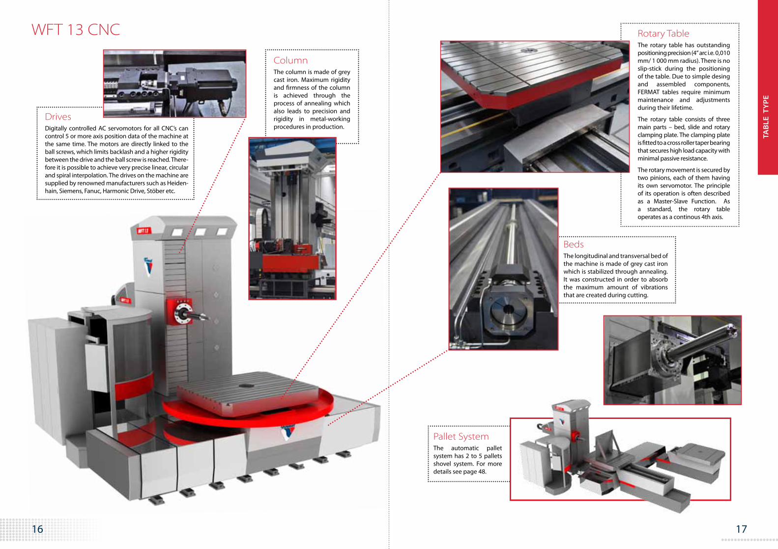
BedsThe longitudinal and transversal bed of the machine is made of grey cast iron which is stabilized through annealing. It was constructed in order to absorb the maximum amount of vibrations that are created during cutting.
WFT 13 CNC Rotary TableThe rotary table has outstanding positioning precision (4“ arc i.e. 0,010 mm/ 1 000 mm radius). There is no slip-stick during the positioning of the table. Due to simple desing and assembled components, FERMAT tables require minimum maintenance and adjustments during their lifetime.
The rotary table consists of three main parts – bed, slide and rotary clamping plate. The clamping plate is fitted to a cross roller taper bearing that secures high load capacity with minimal passive resistance.
The rotary movement is secured by two pinions, each of them having its own servomotor. The principle of its operation is often described as a Master-Slave Function. As a standard, the rotary table operates as a continous 4th axis.
Pallet SystemThe automatic pallet system has 2 to 5 pallets shovel system. For more details see page 48.
ColumnThe column is made of grey cast iron. Maximum rigidity and firmness of the column is achieved through the process of annealing which also leads to precision and rigidity in metal-working procedures in production.
DrivesDigitally controlled AC servomotors for all CNC’s can control 5 or more axis position data of the machine at the same time. The motors are directly linked to the ball screws, which limits backlash and a higher rigidity between the drive and the ball screw is reached. There-fore it is possible to achieve very precise linear, circular and spiral interpolation. The drives on the machine are supplied by renowned manufacturers such as Heiden-hain, Siemens, Fanuc, Harmonic Drive, Stöber etc.
TAB
LE T
YP
E

19 18
Technical parameters Metric System | Inch System WRFT 130
Diameter of Spindle mm | in 130 | 5.12”
Taper of Spindle ISO-50 / BT-50 | CAT-50
Range of Spindle Speed RPM 10 - 3 100
Rated Power of Main Engine S1/S6 kW | HP 37 / 56 | 50 / 75
Travel Table X mm 2 400 – 6 100
in 94.49“-240.18“
Headstock Vertical Travel Ymm 2 000 / 2 500 / 3 000 / 3 500 / 4 000
in 78.74” / 98.43” / 118.11” / 137.80“ / 157.48“
Longitudinal Travel Z mm 900 / 1 200 / 2100 / 3 300 / 3900
in 35.43“ / 47.24“ / 82.68“ / 129.92“ / 153.54“
Extension Spindel Travel Wmm 730
in 28.74”
Ram Travel V mm | in 900 (1 000) | 35.43”(39.37“)
Operating Feed X, Y, Z, W mm | in 1-10 000 | 0.04-394.00”
Rapid Traverse X, Y, Z mm.min -1| in min 15 000 | 590.55”
V, W mm.min -1| in min 10 000 | 393.70“
B min -1 2
Max. Table Load kg | lb 25 000 / 40 000 / 50 000 | 55 116 / 88 185 / 11 0231
Table Dimensions mm 2 000x2 000 / 2 000x2 500 / 2 000x3 000 /
2 500x2 500 / 2 500x3 000 / 3 000x3 000
in 78.74“x78.74“ / 78.74“x98.43“ / 78.74“x118.11“ / 98.43“x98.43“ / 98.43“x118.11“ / 118.11“x118.11“
WRFT 130 CNC
The horizontal milling and boring machines WRFT represent the newest technology and concept of large table type horizontal borers with ram travel and moveable spindle. WRFT machines are being used mostly during powerful machining of big and heavy work-pieces up to 50 000 kg | 110 231 lb.
WRFT construction is based on incorpora-tion of components from the WRF Floor Type Series but with the placement of beds in a “T” configuration resulting in a table-type machine with horizontal table travel (X-Axis), CNC rotary table (B-Axis) and longitudinal column travel (Z-Axis). On the guide ways of the column, the headstock travels vertically (Y-Axis) with its horizontal ram travel (V-Axis) and moveable spindle (W-Axis).
Machine configuration:
• WRFT 130 CNC basic machine with spindle diameter 130 mm | 5.19” and ram travel 900 mm | 35.43"
WRFT 130 is optionally equipped with the Automatic Tool Changer (ATC) or the Automatic Pallet Changer System (APC) and with different kinds of Manual or Automatic Milling Heads.
TAB
LE T
YP
E

21 20
25
TA
BL
E T
YP
E
Beds The longitudinal and transversal bed of the machine is made of grey cast iron which is stabilized through annealing. It was constructed in order to absorb the maximum amount of vibrati ons that are created during cutti ng.
Table Type - WRFT 130, 150, 160 CNC
Rotary Table The rotary table has outstanding positi oning precision (4“ arc sec i.e. 0,010 mm/ 1000 mm radius) and high excentric load as a standard. There is no slip-sti ck during the positi oning of the table. Due to simple desing and assembled components, FERMAT tables require minimum maintenance and adjustments during their life ti me.
The table consists of three main parts – slide, bed and rotary clamping plate. The clamping plate is tt ed onto a cross roller taper bearing that secures high load capacity with minimal passive resistance.
The rotary movement is secured by two pinions, each of them having its own servomotor. The principle of its operati on is oft en described as a Master-Slave Functi on. As a standard, the rotary table operates as a conti nous 4th axis.
WRFT 130 CNC
Beds
Rotary Table
The longitudinal and transversal bed of the machine is made of grey cast iron which is stabilized through annealing. It was con-structed in order to absorb the maximum amount of vibrations that are created during cutting.
25
TA
BL
E T
YP
E
Beds The longitudinal and transversal bed of the machine is made of grey cast iron which is stabilized through annealing. It was constructed in order to absorb the maximum amount of vibrati ons that are created during cutti ng.
Table Type - WRFT 130, 150, 160 CNC
Rotary Table The rotary table has outstanding positi oning precision (4“ arc sec i.e. 0,010 mm/ 1000 mm radius) and high excentric load as a standard. There is no slip-sti ck during the positi oning of the table. Due to simple desing and assembled components, FERMAT tables require minimum maintenance and adjustments during their life ti me.
The table consists of three main parts – slide, bed and rotary clamping plate. The clamping plate is tt ed onto a cross roller taper bearing that secures high load capacity with minimal passive resistance.
The rotary movement is secured by two pinions, each of them having its own servomotor. The principle of its operati on is oft en described as a Master-Slave Functi on. As a standard, the rotary table operates as a conti nous 4th axis.
Column (Y-axis)FERMAT developed a unique construction of the column (single piece design of the column and the slide, two or three ball screws for 130 mm to 160 mm | 5.19" to 6.30” spindle diameter. No hydraulic or mechanical counterweight allows for the column to be heavily reinforced for extra strength. Maximum rigidity and firmness of such a unison is achieved through the process of thermal stabilization, which ultimately leads to increased precision and rigidity of the metal-working procedure.
Ram (V-axis)To achieve the best features of the ram ductile iron, a whole complex of annealing methods have been applied. Higher accuracy of the ram axis is achieved by two ball screws (the so-called Gantry Axis) and two Linear Positioning Scales. Thanks to this, maximum safety with high precision and quality productions can be consistently ensured.
The rotary table has outstanding po-sitioning precision (4“ arc sec i.e. 0,010 mm/ 1 000 mm radius). There is no slip-stick during the posi-tioning of the table. Due to simple “design” and assembled components, FERMAT tables require minimum main-tenance and adjustments during their life time.
The table consists of three main parts – slide, bed and rotary clamping plate. The clamping plate is fitted onto a cross roller taper bearing that secures high load capacity with minimal passive re-sistance.
The rotary movement is secured by two pinions, each of them having its own servomotor. The principle of its operation is often described as a Master-Slave Function. As Standard, the rotary table operates as a continous 4th axis.
TAB
LE T
YP
E

23 22
WFC 13 CNC
WFC 13 CNC machine is a horizontal boring mill with a live spindle of diameter 130 mm | 5.12” (optionally 110 mm | 3.94” ) and a maximum table load up to 8 000 kg | 17 637 lb. The machine has a sturdy construction allowing demanding achining of cast, steel and cast steel workpieces.
This machine concept is based on fixed column which provides absolute firmness necessary for precise machining and two crossed horizontal beds for table (X and Z axes). Both beds and column are made of grey cast iron which is stabilized through annealing to absorb the maximum of vibrations caused by cutting.
Machine configurations:
• WFC 13 CNC – Basic machine with a spindle diameter of 110mm | 3.94”
• WFC 13 CNC – Basic machine with a spindle diameter of 130mm | 5.12”
Technical parameters Metric System | Inch System WFC 13
Diameter of Spindle mm | in 110 | 4.33” 130 | 5.12”
Taper of Spindle ISO-50, BT-50 | CAT-50
Range of Spindle Speed RPM 10-3 100
Rated Power of Main Engine S1/S6 kW | HP 37/56 | 50/75“
Travel Table X mm | in 2 500 | 98.43"
Headstock Vertical Travel Ymm 1 700 / 2 000 / 2 500
in 66.93“ / 78.74“ / 98.43“
Longitudinal Travel Z mm | in 1 600 | 62.99“
Extension Spindel Travel W mm | in 730 | 28.74“
Operating Feed X, Y, Z, W mm | in 1-10 000 | 0.04”- 393.70”
Rapid Traverse X, Y, Z mm.min -1| in min 10 000 | 393.70”
W mm.min -1| in min 8 000 | 314.91“
B min -1 2
Max. Table Load kg | lb 8 000 | 17 637
Table Dimensions mm 1 200x1 200 / 1 200x1 400 / 1 400x1 600 / 1 600x1 600
in 47.24“x47.24“ / 47.24“x55.12“ / 55.12“x62.99“ / 62.99“x62.99“
Column and Beds
Rotary Table
The concept is based on fixed column which provides absolute firmness necessary for precise ma-chining and two crossed horizon-tal beds for table (X and Z axes). Both beds and column are made of grey cast iron which is stabilized through annealing to absorb the maximum of vibrations caused by cutting. X Axes is supported by two 45° diagonal supports.
The table consists of slide, bed and rotary clamping plate. High load capacity and minimal passive resistance is secured by cross taper roller bearing under the clamping plate.
HeadstockHeadstock of WFC 13 CNC is equipped with a live spindle of 130 mm | 5.12” in diameter. FER-MAT can optionally provide this machine with spindle diameter 110 mm | 4.33".
TAB
LE T
YP
E

25 24
WFC 10 CNC
The WFC 10 CNC machine is a new model of horizontal boring mill equipped with a spindle diameter of 100 mm |3.94”. It is the smallest horizontal boring machine from the Fermat production suitable for machining for machining of smaller and medium sized work pieces up to 3000 kg | 6614 lb.
WFC 10 CNC is built in a standard configu-ration with a fixed column, moveable spin-dle and crosswise moveable rotary table. Due its high reliability, high cutting perfor-mance with easy of operation. The com-bination of operator friendly, high cutting performance and lower cost makes the WFC 10 CNC very popular with our clients.
WFC 10 CNC is optionally equipped with the Automatic Tool Changer (ATC), Coolant Through Spindle, Chip Conveyor or Auto-matic Pallet Changer System (APC).
Machine configuration:
• WFC 10 CNC – Basic machine with a spindle diameter of 100mm | 3.94”
Technical parameters Metric System | Inch System WFC 10
Diameter of Spindle mm | in 100 | 3.94”
Taper of Spindle ISO-50 / BT-50 | CAT-50
Range of Spindle Speed RPM 10-2 000 (3 000)*
Rated Power of Main Engine S1/S6 kW | HP 17/25, 22/33 | 23/36, 26/44
Travel Table Xmm 1 250 / 2 000
in 49.21“ / 78.74“
Headstock Vertical Travel Ymm 1 250 / 1 700
in 49.21” / 66.93”
Longitudinal Travel Zmm 1 250
in 49.21”
Extension Spindel Travel W mm | in 730 | 28.74"
Operating Feed X, Y, Z, W mm | in 4-4 000 | 0.18“-157.48“
Rapid Traverse X, Y, Z, W mm.min -1| in min 1-8 000 | 0.04“-314.96“
B min -1 2
Max. Table Load kg | lb 3 000 (5 000) | 6614“ (11 023)
Table Dimensions mm 1 000x1 120 / 1 200x1 400
in 39.37“x44.09“ / 47.24“x55.12“
*Max. Spindle Travel 500 mm | 19.69“
TAB
LE T
YP
E

27 26
WRF 130 PortableSee page 31
Floor Type Horizontal Boring Mills Our products
One of the main characteristics of the FERMAT floor type horizontal boring and milling machines is their powerful milling and drilling chip removal (even at the top of the Y axis stroke) and higher precision than is offered by other machines available on the market. The large variation of selectable parameters is combined with its broad range of operating functions. The main feature is a modular concept that allows greater production variables and rapid set-up through the use of peripheral tools and accessories.
The machine moves in 3 or 4 different axes (X, Y, Z and W for borers). An additional B and/or V-axis is added when the machine is equipped with the rotary table. Several clamping plates can be joined together, or in combination with a rotary table to achieve specialized configurations easily and quickly.
The basic model of the machine comes with Heidenhain, Fanuc or Siemens controls and drives.
Work pieces can be clamped either on the additional rotary table, on the clamping plates, or using both these possibilities.
The main working purpose of the machines is chip removal from large and heavy steel, cast steel, or cast iron work pieces. The ma-chine’s technology allows a wide utilization in milling, boring, reaming, and threading processes. FERMAT machines stand out thanks to their capacity to achieve higher precision than their competitors.
Horizontal Boring and Milling Machines – Floor Type
WRF SeriesSee page 28
WF 13See page 32
”We have now seen that big boring mill on linear guideway is works wery vell. Also when working with spindle and ram out, and the machine is economical compare to hydrostatic machines, and also Fermat machine have long stroke on spindle 1000 mm/39.37“. We find the service well with quick response as well, and also the technicians in Fermat help us to improve smart solutions where we save cost. After 2 years of using FERMAT Horizontal Boring Mills in Sæby we decided to order a third floor type WRF boring mill as we got a new order for heavy parts subcontracting for wind power industry. ”
Michael Jacobsen, President of Nordmark Maskinfabrik A/S, Denmark
FLO
OR
TY
PE

29 28
Horizontal Boring Machines WRF Series Technical parameters Metric System | Inch System WRF 130 WRF 150 WRF 160
Diameter of Spindle mm | in 130 | 5.12” 150 | 5.90” 160 | 6.30“
Taper of Spindle ISO-50 / BT-50 | CAT-50 ISO-50 (60) / BT-50(60) | CAT-50 (60)
Range of Spindle Speed RPM 10-3 000 10-2 800 10-2 500
Rated Power of Main Engine S1/S6 kW | HP 37/56 | 40/60 51/77| 68/103 60/80 | 80/107
Travel Column Travel Xmm 2 400-28 100
in 94.49“-1 106“
Vertical Headstock Travel Y mm | in 2 000-6 000 | 78.74”-236.22”
Longitudinal Travel Zmm 900 1 000 (1 200 / 1 500)
in 35.43“ 39.37“ (74.24“ / 59.06“)
Extension Spindel Travel W mm | in 730 | 28.74“ 1 000 | 39.37"
Longitudinal Table Travel Vmm 1 200 / 2 400 / 3 600
in 74.24" / 94.49" / 141.73"
Operating Feed X, Y, Z, W mm | in 1-10 000 | 0.003"-393.70"
V mm | in 1-8 000 | 0.04“-315“
B RPM 0-1.7
Rapid Traverse X mm.min -1| in min 1-20 000 | 0.003“-787.40“
Y, V mm.min -1| in min 1-15 000 | 0.003“-590.51“
Z, W mm.min -1| in min 1-12 000 | 0.003“-472.44“
B RPM 2
Max. Table Load kg | lb 25 000–50 000 | 55 116–110 231
Table Dimensions mm 2 000x2 000 / 2 000x2 500 / 2 000x3 000 / 2 500x2 500/
2 500x3 000 / 3 000x3 000 / 3 500x3 500
in 78.74“x78.74“ / 78.74“x98.43“ / 78.74“x118.11“ / 98.43“x98.43“/98.43“x118.11“ / 118.11“x118.11“ / 137.80“x137.80“
Horizontal Boring Machines WRF are the biggest representatives of FERMAT boring mill production. They are used mainly for precise and powerful machining of big and heavy work pieces from iron, cast steel and steel. Our machines are usually intended for machining of large energy parts, crane or ship parts, oil and gas equipment and similar structures.
WRF 130, 150, 160 CNC are equipped with a horizontally and vertically moveable operator´s cabin. Machines can be delivered with a wide range of accessories that en-hance the high technology provided.
Machine configurations:
• WFR 130, 150, 160 – Basic configuration
• WRF 150 TR – Machine configuration with tilting headstock
• WRF 130 PORTABLE
• WRF 160 H - Machine configuration with hydrostatic X Axis
• WRF 160, WRF 160 H - Option: machine with box way guided ram travel 1 500 mm | 59.05" and spindle travel 1 000 mm | 39.37"
FLO
OR
TY
PE

31 30
Column (Y-axis)FERMAT developed a unique construction of the column (single piece design of the column and the slide, two or three ball screws for 130 mm | 5.12" spindle diameter or three for 150 mm | 5.90" and 160 mm | 6.30" spindle diameter, no counterweight). Maximum rigidity and firmness of such a unison is achieved through the process of thermal stabilization, which ultimately leads to increased precision and rigidity of the metal-working procedure.
Ram (Z-axis)To achieve the best features of the ductile iron ram, ductile iron, a whole complex of annealing methods have been applied. Higher accuracy of the ram axis is achieved by two ball screws (the so-called Gantry Axis) and two Linear Positioning Scales. Thanks to this, maximum safety with high precision and quality productions can be consistently ensured.
WRF SERIES WRF 130 CNC Portable
HeadstockThe headstock is comprised of a ram travel drive, a live spindle and a two-speed gearboxes, which is guided automatically by spindle rpms. A modern AC motor is used to control the fluency of revolutions. The casting is made from special ductile iron.
Column (Y-axis)FERMAT developed a unique constructi on of the column (single piece design of the column and the slide, two ball screws for 130 mm spindle diameter or three for 150 and 160 mm spindle diameter, no counterweight). Maximum rigidity and rmness of such a unison is achieved through the process of thermal stabilizati on, which ulti mately leads to increased precision and rigidity of the metal-working procedure.stabilizati on, which ulti mately leads to increased precision andrigidity of the metal-working procedure.
Floor Type - WRF 130, 150, 160 CNC
Bed The bed of the machine is made of grey cast iron, and is stabilized through annealing. It was constructed in order to absorb the maximum amount of vibrati ons which are created during the cutti ng process. It features heavy duty Schneeberger (INA, THK) linear guide ways, further contributi ng to the precision and rigidity of the machine.
FL
OO
R T
YP
E
13
BedsThe bed of the machine is made of grey cast iron and is stabilized through annealing. It was con-structed in order to absorb the maximum amount of vibrations which are created during the cut-ting process. It features heavy duty Schneeberger (INA, THK) linear guide ways further contributing to the precision and rigidity of the machine.
Technical parameters Metric / Inch WRF 130 CNC PortableDiameter of spindle mm | in 130 | 5.12”
Taper of spindle ISO 50 / BT 50 | CAT 50
Range of spindle speed RPM 10-3 000
Rated Power of main engine S1/S6 kW | HP 37/56 | 50/75
Horizontal Column Travel X mm | in 2 400- 4 300 | 94.49”-169,29”
Vertical Column Travel Y mm | in 2 000-4 000 | 78.74”-157.48”
Ram Travel Z mm | in 900 | 35.43”
Spindle Travel W mm | in 730 | 28.74”
Operating Feed All Axes X,Y,Z,W mm. min-1 | in min 1-10 000 | 0.003”- 393.70”
Rapid Travel X, Y, Z, W mm. min-1 | in min 1-10 000/1-20 000/1-18 000/1-12 000 393.70”/787.40”/708.66”/472.44”
The portable horizontal boring WRF 130 CNC allows an easy transfer of the machine outside a permanent basis to the desire location. This is used while machining large parts, which can not be transferred easily, such as parts for the construction of large energy parts, ships, etc. In this design the column has a supporting/lifting rod at the top for moving the machine within the plant. The power cables and coolant hoses are equipped with couplings for easy re-connection. Similarly, anchoring and balancing the machine is designed to facilitate the alignment geometry in place. WRF 130 portable is equipped with a horizontally and vertically moveable operator‘s enclosure. Technological possibilities of the machine can be further enhanced by accessories offered with all WRF 130 CNC machines.
FLO
OR
TY
PE

33 32
Technical parameters Metric System | Inch System WF 13
Diameter of Spindle mm | in 130 | 5.12” (110 | 4.33”)
Taper of Spindle ISO- 50 / BT-50 | CAT-50
Range of Spindle Speed RPM 10-3 000
Rated Power of Main Engine S1/S6 kW | HP 37/56 | 50/75
Travel Table X mm 2 800-6 800 (by 500) / 7 800 -22 800 (by 1 000)
in 110.24“- 267.72“ (by 20“) / 307.09“ - 897.64“ (by 39“)
Headstock Vertical Travel Ymm 1 700 / 2 000 / 2 500 / 3 000 / 3 500
in 66.93" / 78.74" / 98.43" / 118.11" / 137.80"
Longitudinal Travel Z mm | in 600 | 23.62"
Extension Spindel Travel W mm | in 730 | 28.74"
Operating Feed X, Y, Z, W mm.min -1 /in min 1-8 000 | 0.04"-314.96"
W, Z mm.min -1 /in min 1-6 000 | 0.04”-236.2”
B RPM 1-1.7
Rapid Traverse X, Y, Z, V mm.min -1 /in min 12 000 / 8 000* | 474.44" / 314.91"*
W mm.min -1 /in min 10 000 / 8 000* | 393.70" / 314.91"*
B RPM 2
Max. Table Load kg | lb 15 000 / 20 000 | 33 069 / 44 092
Table Dimensions mm 1 600x1 800 / 1 800x2 200 / 2 000x2 400
in 63.00"x70.87" / 70.87"x86.61" / 78.74"x94.50"
* For Axial and Radial Force
A Floor type horizontal boring mill WF type is a basic CNC machine from FERMAT production. The machine is designed for precise and highly efficient coordinate boring, drilling, milling, and cutting of threads of big and heavy work pieces up to 20 000 kg | 4092 lb of large and rugged work pieces from cast iron, cast steel and steel. The machine can be equipped with floor plates and/or rotary table(s) according to machining requirements. As with all Fermat Boring Mills a wide range of accessories can be added that considerably enhance the machine’s versatility.
WF 13 CNC
Machine Configurations:
• WF 13 CNC Basic Machine with moveable spindle 130mm | 5.12” ( 110mm | 4.33” spindle as an option)
• WF 13 R Machine with ram travel
FLO
OR
TY
PE

35 34
BedsThe bed of the machine is made of grey cast iron which is stabi-lized through annealing. It was constructed in order to absorb the maximum amount of vibrations that are created during cutting. Guideways are hardened.
WF 13 CNC
Headstock The WF 13 CNC headstock of WF 13 CNC is equipped with a live spindle with travel 730 mm|28.74" and and additional ram travel of 600 mm| 23.62" can also be incorporated.
ColumnThe column is made of grey cast iron. Maximum rigidity and firmness of the column is achieved through the process of annealing, which maximizes highest precision and machining results.
FLO
OR
TY
PE

37 36
Universal milling machine FGU (RT) CNC
Other Products
FGU milling machine is a universal CNC milling machine for machining parts with lengths up to 5000 mm |197” and height up to 3500 mm |138”. It is especially suitable for machining from 5 sides thanks to its built in automatic micro-positioning 2 axis head. Rigid machine frame design with weight over 40 000 kg | 88185 lb guaranties precise work piece geometry and dimensions after machining as well as allows productive chip removal.
As standard, the allowing machine is equipped with micro positioning head UHAmi 30. Automatic head transmits 30kW| 40HP output, 1600 Nm and it is rated from 10 to 3000 rpm. It can be positioned in any an-gle with increment of 0.001 degree. After po-sitioning the head is hydraulicaly clamped. FGU can be equipped with automatic tool changer or robot. The Robot can change the tools in any angular position of the Head. This feature brings significant time savings as well. The Robot also can handle even heavier tools as an option.
Machine is available with built-in with CNC rotary table for maximum work piece load 15 000 or 20 000 kg |33069 or 44092 lb. For machining of long work pieces a plain table can be supplied.
Precise machining from 5 sides and any angles can decrease the number of work piece setups. This contributes to productivity and higher precision. It is ideal for machining parts such as as hydraulic blocks, pumps, molds and dies, etc.
Technical parameters Metric System | Inch System FGU FGU – RT
Diameter of Spindle ISO- 50 / BT-50 | CAT-50
Range of Spindle Speed RPM 10 - 3 000 (4 000)
Rated Power of Main Engine S1 kW | HP 30 | 40
Travel Table X mm | in 3 200 | 125.98” 1 500-5 000 (by 500) | 59.064" - 196.85" (by 19.69")
Headstock Vertical Travel Y mm | in 1 700 / 2 000 / 2 500 | 66.93” / 78.74” / 98.43”
Longitudinal Travel Z mm | in 1 600 | 62.99"
Operating Feed X, Y, Z mm.min -1 /in min 4 - 8 000 | 0.18"- 314.96"
B min -1 1-1.7
Rapid Traverse X mm.min -1 10 000 | 393.70"
Y, Z mm.min -1 10 000 | 393.70” 10 000 | 393.70“
B min -1 2
Max. Table Load kg | lb 10 000 | 22 046 15 000 / 20 000 | 33 069 / 44 092
Table Dimensions mm 1 000 x 3 600 1 200x1 400*/1 600x1 800/1 800x2 200/2 000x2 400
in 39.37“x141.73” 47.24”*x55.19”/63.00“x70.87“/ 70.87“x86.61“/78.74“x94.50“
* 10 000 kg | 22 046 lb
OT
HER
PR
OD
UC
TS

39 38
WRF MILL CNC is similar to the rest of the WRF line, with the exception of a longer ram travel, and without a travelling spindle. This configuration provides a mounting platform for a variety of attachments such as automatic angle heads, milling heads, or facing heads.
The basic floor plan of WRF MILL CNC ma-chines is horizontal column travel (X-axis), vertical headstock travel (Y-axis) and horizon-tal ram travel of rectangular profile (Z-axis).
Universal milling machine WRF MILL
Technical parameters Metric System | Inch System WRF MILL
Ram Dimension mm | in 400 x 500 | 15.75"x19.65"
Taper of Spindle ISO - 50 / BT - 50 | CAT - 50
Range of spindle Speed RPM 10-4 000
Rated Power of Main Engine S1/S6 kW | HP 37/56 | 50/75
Horizontal Column Travel X mm | in 2 400- 28 100 | 94.49" - 1106"
Vertical Column Travel Y mm | in 2 000 - 6 000 | 78.74" - 236.22"
Ram Travel Z mm | in 1 500 | 59.06“
Longitudinal Table Travel V mm | in 1 200 / 2 400 / 3 600 | 47.24“ / 94.49“ / 141.73“
Operating Feed X, Y, Z mm.min -1 | in min 1-10 000 | 0.04"- 393.70"
B min -1 0-1.7
V mm.min -1 | in min 1-8 000 | 0.04" - 314.96"
Rapid Traverse X mm.min -1 | in min 1-20 000 | 0.04"-787.40"
Y, V mm.min -1 | in min 1-15 000 | 0.04“- 590.55”
Z min -1 1-10 000 | 0.04" - 393.70"
V mm.min -1 | in min 15 000 | 590.55"
Max. Additional Table Load kg | lb 25 000 / 40 000 / 50 000 | 55 116 / 88 185 / 110 231
Table Dimensions mm 2 000x2 000 - 3 500x3 500
in 78.74“x78.74" - 137.76"x137.76"
* linear guide waysUniversal Manual Head
Spindle Extension
Universal Automatic Head
CNC Facing Head
OT
HER
PR
OD
UC
TS
41 40
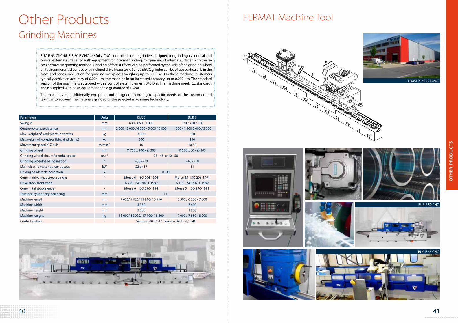
BUC E 63 CNC/BUB E 50 E CNC are fully CNC-controlled centre grinders designed for grinding cylindrical and conical external surfaces or, with equipment for internal grinding, for grinding of internal surfaces with the re-cess or traverse grinding method. Grinding of face surfaces can be performed by the side of the grinding wheel or its circumferential surface with inclined drive headstock. Series E BUC grinder can be of use particularly in the piece and series production for grinding workpieces weighing up to 3000 kg. On these machines customers typically achive an accuracy of 0,004 µm, the machine in an increased accuracy up to 0,002 µm. The standard version of the machine is equipped with a control system Siemens 840 D sl. The machine meets CE standards and is supplied with basic equipment and a guarantee of 1 year.
The machines are additionally equipped and designed according to specific needs of the customer and taking into account the materials grinded or the selected machining technology.
Grinding Machines
XC
Z
Parameters Units BUC E BUB E
Swing Ø mm 630 / 850 / 1 000 320 / 400 / 500
Centre-to-centre distance mm 2 000 / 3 000 / 4 000 / 5 000 / 6 000 1 000 / 1 500 2 000 / 3 000
Max. weight of workpiece in centres kg 3 000 500
Max. weight of workpiece flying (incl. clamp) kg 300 150
Movement speed X, Z axis m.min-1 10 10 / 8
Grinding wheel mm Ø 750 x 100 x Ø 305 Ø 500 x 80 x Ø 203
Grinding wheel circumferential speed m.s-1 25 - 45 or 10 - 50
Grinding wheelhead inclination ° +30 /–10 +45 / -10
Main electric motor power output kW 22 or 17 11
Driving headstock inclination k 0 -90
Cone in drive headstock spindle ° Morse 6 ISO 296-1991 Morse 65 ISO 296-1991
Drive stock front cone - A 2-6 ISO 702-1-1992 A 1-5 ISO 702-1-1992
Cone in tailstock sleeve - Morse 6 ISO 296-1991 Morse 5 ISO 296-1991
Tailstock cylindricity balancing mm ±1
Machine length mm 7 626/ 9 626/ 11 916/ 13 916 5 500 / 6 700 / 7 800
Machine width mm 4 350 3 400
Machine height mm 2 888 1 950
Machine weight kg 13 000/ 15 000/ 17 100/ 18 800 7 000 / 7 850 / 8 900
Control system - Siemens 802D sl / Siemens 840D sl / BaR
BUB E 50 CNC
BUC E 63 CNC
FERMAT Machine Tool
FERMAT PRAGUE PLANT
Other Products
OT
HER
PR
OD
UC
TS

43 42
The WRF, WF, WFT, WFC and WRFT series are equipped with a standard boring mill live spindle. The headstock provides an adjustable mounting platform for a variety of attachments such as CNC angle heads, manual angle heads, support spindle sleeves, etc. The headstock is driven by a servo drive. The two-speed automatic gearbox gives enough torque for heavy metal chip removal and for powerful high-speed drilling. FERMAT machines are also capable of high-performance manufacturing due to the spindle axial force of 40,000 Nm. In WRF and WRFT series, two Y-axis ball screws with two Heidenhain scales control slide ram deflections. The third ballscrew in the torque position that is constantly pushing the headstock body upwards is added for 150 and 160 mm | 5.91" and 6.30" headstock. The upper part features heavy duty INA roller linear guideways, further contributing to the precision and rigidity of the machine. WFT machines are equipped with one ballscrew and counterweight system.
All the tables have outstanding positioning precision (4 arc sec. 0.010 mm / 1 000 mm radius). There is no slip-stick during the positioning of the table. Due to simple design and assembled components, FERMAT tables require mini-mum maintenance and adjustments during their lifetime.
The rotary table consists of bed, slide, and rotary clamp-ing plate. The slide enables the rotary clamping plate to move in the V-axis. The clamping plate is fitted onto a cross roller taper bearing that secures high load capacity with
Tool Standard SK (ISO)
Tool Standard ISO
A
B +/- 0,25
C +/- 0,25
SK 40 44,45 94,5 88,25
SK 50 69,85 135,60 126,60
SK 60 107,95 201,65 191,65
Tool Standard BT
A
J +/- 0,3
K +/- 0,3
SK 40 44,45 84,50 79,25
SK 50 69,85 127,00 119,40
SK 60 107,95 199,95 189,45
Tool Standard CAT
A
B +/- 0,25
C +/- 0,25
SK 40 44,45 100,35 93,35
SK 50 69,85 146,75 136,75
SK 60 - - -
Headstock 100, 110, 120, 130, 150, 160
Rotary TableMachine components
WFT 13R
minimal passive resistance. In order to achieve precision in work pieces, the rotary table is hydraulically clamped at eight points (T25, T40, T50) or four points (T10, T15, T20) to avoid rotation during the working process.
The table is governed by the control system of the ma-chine, and there is a rotary encoder in the centre of the table that facilitates the automatic positioning in incre-ments of 0.001°. As a standard, the rotary table operates as a continous 4th axis.
T10, T15, T20
Clamping Plate Size 1 200x1 400/1 600x1 800/1 800x2 200/2 000x2 400 47.24x55.19, 63.0x70.9/ 70.9x86.6/78.7x94.5 mm in
Maximum Table Load 10 000 15 000 20 000 22 046/33 069/44 092 kg lb
T-Slots – Size 20 H8 22 H8
– Distance (Middle) 125 (160) 4.9 (6.3) mm in
V-axis Travel 1 500 – 5 000 59.1 – 196.8 mm in
Operation Trave V-axis 1 – 8 000 0.05 –315 mm/min in/min
Operation Travel B-axis 0 – 1,7 0 – 1.7 RPM RPM
Rapid Travel V-axis 10 000 393.7 mm/min in/min
T25, T40, T50
Clamping Plate Size 2 000x2 000/2 000x2 500/2 000x3 000/ 2 500x2 500/2 500x3 000/3 000x3 000
78.7x78.7/78.7x98.4/78.7x118.1/ 98.4x98.4/98.4x118.1/118.1x118.1 mm in
Maximum Table Load 25 000 – 50 000 55 115 – 110 231 kg lb
T-Slots – Size 28 H8 28 H8
– Distance (Middle) 160 (250) 6.3 (9.8) mm in
V-axis Travel 1 200 – 9 500 47.2 – 374 mm in
Operation Trave V-axis 1 – 10 000 0.04 – 393.7 mm/min in/min
Operation Travel B-axis 0 – 1,7 0 – 1.7 RPM RPM
Rapid Travel V-axis 20 000 787.4 mm/min in/min
WRF 160
CO
MP
ON
ENT
S

45 44
FERMAT machines are offered with Heidenhain iTNC 530, Fanuc 31i, or Siemens Sinumerik 840D SL equipped with a 15“ LCD display, an operating panel with a keyboard, and an electronic hand-wheel. As an option, our machines can be supplied with Fanuc 0i MD or Heidenhain 620 TNC with 10“ LCD display.
The control system coordinates the continuity of all the axes, and also when peripheral tools are attached, such as a rotary table or a milling head.
Control System
Control Systems
HR 410 HR 520 HR 550
Homp I-pendantStandard
TNC 640
Angle Encoders Linear Encoders Contouring Controls Position Displays Length Gauges Rotary Encoders
The new TNC 640: for the fi rst time, milling and turning are combined in one TNC. Now users can switch as desired between milling and turning—within the same NC program. Switchover is independent of the machine kinematics. It automatically takes the respective operating mode into account and without any additional action. This new sim-plicity is complemented by dialog-guided plain language programming, the optimized user interface, powerful pro-gramming aids as well as comprehensive cycle packets taken from amply fi eld-proven HEIDENHAIN controls into the new TNC 640. This is a built-in technological edge. DR. JOHANNES HEIDENHAIN GmbH, www.heidenhain.de
The new high-end control for milling and
turning operations
CO
MP
ON
ENT
S

47 46
Guiding surfaces are covered lenghtwise and crosswise with telescopic covers.
Telescopic Covers
Lubrication of linear guide ways and ball screws (X, Y, and Z-axis) is performed by a special lubrication unit.
The Central Lubrication System is designed with progressive dividers that distribute specific amounts of lubricant.
Lubrication Unit
Electrical devices are mostly located in the switchboard. It includes the basic unit of the control system, components for motor drive of the axis and spindle, and other electrical features made by renowned manufacturers such as Schneider, Telemechanique and Siemens. The switchboard is being cooled by a unit built in the door of the switchboard made by Rittall.
Switchboard Horizontal movement on X-axis longer than 6 m | 236.22" is secured by a rack with two pinions that are in a Master-Slave relationship.
Rack
The X, Y, Z and V axes are equipped with linear scales that ensure the accuracy of the machine.
The W-axis is measured directly from the servomotor encoder or optionally by a Heidenhain linear scale.
Measurement of spindle revolutions is performed by the direct rotary encoder that allows for the desired positioning of the spindle. All final positions of the particular axes are secured by a limit switch.
Linear Scales Heidenhain
Electrical | Hydraulic | Lubrication Units Other Components
Roller linear guide ways enable a higher speed of movement and a smaller force needed for the machine’s movement. This results in higher accuracy of positioning with smaller energy consumption, and longer operating life for components such as ballscrews, servomotors, etc. This solution requires minimum maintenance and simplified, quicker eventual repairs.
X, Y, Z, and W-axis movement is facilitated by ballscrews with the favorable characteristic of very low friction. Thanks to the precision tolerances between the nut and the screw, high rigidity and accuracy is achieved.
Ballscrews
Linear Guide Ways
An integral part of the machine is a Hydraulic Aggregate used for unclamping of a tool from the spindle. On the front side, there is a liquid level gauge, with a thermometer, for visual level and temperature checks of oil in the tank.
Hydraulic Aggregate CO
MP
ON
ENT
S

49 48
AccessoriesAutomatic Pallet Changer System:
Automatic Tool Changer ATC, Robots
APC- Automatic Pallet Changer System
The Automatic Pallet Changer System on the machine reduces unproductive time during machining. Machi-ning can be carried out on one pallet, while the others can be used for preparation (cleaning of table, set up of work-piece, etc). The APC system consists of two or more pallets (according to customer requirements).
Pallet dimension:1 600 x 1 800 mm/63.00x70.87” - maximum load 15 t/33 069 lb1 800 x 2 200 mm/70.87x86.61” - maximum load 15 t/33 069 lb1 200 x 1 200 mm/47.24“ x 47.24“ - maximum load 5 t/11 023 lb*1 200 x 1 400 mm/47.24“ x 55.12“ - maximum load 5 t/11 023 lb* 1 400 x 1 600 mm/55.12“ x 63.00“ - maximum load 5 t/11 023 lb**available with 2 to 5 pallets
Description of pallet change The pallet exchange process is performed in five phases:
1. The pallet is unclamped from the X axis. The shif-ting slide is connected to the rotation slide on the X-axis by pins inserted into the lock.
2. The pallet itself is moved by a chain, where it is pulled by the pin up to the clamping position.
3. The X axis slides moves infront of the next pallet with the workpiece loaded.
4. The new pallet is shifted to X axis slides, then the shifting slide retracks.
5. The Pallet is clamped to the X axis.
Automatic Pallet Changer System by Fermat can save you time and increase the flexibility of produc-tion & business competitiveness.
Automatic tool change is accomplished by a chain (for 20, 32, 40, 60 and 90 tools). Tool changer can exchange tool into the live spindle as well to automatic head spindle.
Fermat is always adapting to new requirements of the market and wishes of its customers. One of the important innovations is that our company as a first producer of Horizontal Boring Mills is planning to substitute Automatic Tool Changers by 6-Axe high tech German Robots (Standard Automatic Tool Changer will still exist as an option for consumer request).
The advantage is that the robot can change tools directly into many positions, for example into heads, spindle support sleeves, etc. Furthermore, another benefit is low maintenance requirements or the possibility of higher weight of the tools. For example a robot has a capacity to hold the tool with weight about 75 kg|165 Ib. Generally the robot is meant to bring to the consumer a luxury of fast, precise and effective tool exchange.
Automatic Tool Changer for 20, 32, 40, 60 or 90 tools
Robots
AC
CES
SO
RIE
S

51 50
284
848
968
544
400
128,57
380 mm | 14.96" 555 mm | 21.85"
225
325
806
926
430
485
225
Universal micro-indexing milling head - UHAmi 30
• Spindle Taper SK 50 (DIN, ANSI, MAS)
• Hydraulic Tool loosing
• Tool clamping force 20 kN
• Angle contact High precision bearings mounted on the tool-holder spindle, trio at the forward side and couple the back side
• Ground gears
• Tool cooling, AXIAL through the main spindle
• External tool cooling
• Rotary encoder at both axes
• Taper air-jet
• A axis range ± 180°
Speed: 10-3000 rpm
Power: 30 kW
Torque: 1600 Nm
Indexing: 0,001°
Clamping torque: A axis - 3800 Nm C axis - 6500 Nm
Universal Automatic Head UHA 30 - automatically attached to the headstock, automatic positioning, automatic tool clamping and unclamping.
Revolutions: 3 000 RPM
Maximum Power: 30 kW (40 HP)
Maximum Torque (150 RPM): 1 600 Nm
Tool: ISO 50 – DIN 69871
Pull Stud : DIN 69872
Turning: 2,5°/ 2,5° (1°/ 1°)
Coolant Through Spindle: Standard
Right Angle Manual Head PHM 37 - manually attached to the headstock, manual positioning, automatic tool clamping and unclamping.
Revolutions: 3 000 RPM
Maximum Power: 37 kW (50 HP)
Maximum Torque (150 RPM): 2 000 Nm
Tool: ISO 50 - DIN 69871
Pull Stud: DIN 69872
Turning: any degree (optionally 2,5°/1°)
Coolant Through Spindle: Option
UHM 30
UHA 30
PHM 37
Milling and Facing HeadsUniversal Manual Head UHM 30 - manually attached to the headstock, manual positioning, automatic tool clamping and unclamping.
Revolutions: 3 000 RPM
Maximum Power: 30 kW (40 HP)
Maximum Torque (150 RPM): 1 600 Nm
Tool: ISO 50 – DIN 69871
Pull Stud : DIN 69872
Turning: any degree (optionally 2,5°/ 2,5°; 1°/ 1°)
Coolant Through Spindle: Not Possible
Right Angle Automatic Head PHA 37
- automatically attached to the headstock, automatic positioning, automatic tool clamping and unclamping.
Revolutions: 3 000 RPM
Maximum Power: 37 kW (50 HP)
Maximum Torque (187 RPM): 2 000 Nm
Tool: ISO 50 – DIN 69871
Pull Stud: DIN 69872
Turning: 2,5° (1°)
Coolant Through Spindle: Standard
PHA 37
250 mm | 9.84"
Spindle Support Sleeves
267
650
497
760 400
128,56
AC
CES
SO
RIE
S

53 52
Two Axis Orthogonal Milling Head
- manually attached to the headstock, manual positioning, manual tool clamping and unclamping.
Revolutions: 10 - 1 000 RPM
Maximum Power: 55 kW (74 HP)
Maximum Torque: (150 RPM): 2 600 Nm
Tool: ISO 50/60
Turning: 0° - 360°
Coolant Through Spindle: Not Possible
IFVW 3B
380
865
755
480
220
Right Angle Milling Head
- manually attached to the headstock, manual positioning, manual tool clamping and unclamping.
Revolutions: 10 - 1 000 RPM
Maximum Power: 55 kW (74 HP)
Maximum Torque: (150 RPM): 2 600 Nm
Tool: ISO 50/60
Turning: 0° - 360°
Coolant Through Spindle: Not Possible
IFVW 2B
Right Angle Milling Head
- manually attached to the headstock, manual positioning, manual tool clamping and unclamping.
Revolutions: 10 - 2 000 RPM
Maximum Power: 10 kW (13 HP)
Maximum Torque: (150 RPM): 180 Nm
Tool: ISO 40
Turning: 0° - 360°
Coolant Through Spindle: Not Possible
IFVW 1B
Right Angle Manual Milling Head
- manually attached to the headstock, manual positioning, manual tool clamping and unclamping
Revolutions: 2000 RPM
Maximum Power: 20kW (27HP)
Tool: SK 50 (DIN, MAS, ANSI)
PHM 20
Two Axis Orthogonal Manual Milling Head
- manually attached to the headstock, manual positioning, manual tool clamping and unclamping
Revolutions: 2000 RPM
Maximum Power: 20kW (27HP)
Tool: SK 50 (DIN, MAS, ANSI)
OHM 20
Milling and Facing Heads
625
400
560
200
12
8,56
21
0
130
25,4
397
182
311
280
128,57
325
380
865
755
480
220
544
200
440
300
12
8,57
Plate Diameter: 500 mm | 19.68"
Positioning: Automatic
Boring Accuracy: 0,01 mm | 0.0004"
Radial Traverse: 160 mm | 6.30"
Maximum Boring Diameter: 1 000 mm | 3.94"
Coolant Through Spindle: Standard
D‘Andrea Facing Head UT 5-500 S (UT 5-630, UT5-800)
- automatically or manually attached to the headstock, automatic clamping and unclamping
Revolutions: 6000 RPM
Maximum Power: 37kW (50HP)
Maximum Torque: 182,5 Nm
Tool: ISO 50 –DIN 69871
Coolant Through Spindle: Standard
Outside Coolant: Standard
Speeding Head
UHM 20Two Axis Universal Manual Milling Head
- manually attached to the headstock, manual positioning, manual tool clamping and unclamping
Revolutions: 2000 RPM
Maximum Power: 20kW (27HP)
Tool: SK 50 (DIN, MAS, ANSI)
1255
90
1320 450
485
95
Plate Diameter: 650/800 mm | 19.68"/31.50"
Positioning: Automatic
Boring Accuracy: 0,05 mm | 0.002"
Radial Traverse: 170/220 mm | 6.69"/8.66"
Maximum Boring Diameter:
1 200/1400 mm | 47.24"/55.19"
Coolant Through Spindle: Not Possible
Automatic Facing Head FH 65/80
154
372
460 280
128,57
294
AC
CES
SO
RIE
S

55 54
Inside the cabin, there is a main Control Panel and a prepared storage area for machine tools. The platform is equipped with suitable protection covers and a lockable door, which is secured by electromagnetic switches.
Operator‘s platform on floor type machines is standardly equipped with a horizontal and vertical adjustment. For table type series, the platform is either fixed or moveable in vertical and horizontal direction.
Operator‘s Platforms Table & Workspace Enclosures
Table dimension [mm]
Height[mm]
1 600x1 800 1 750
1 800x2 200 1 750
2 000x2 400 2 000
Plexi table cover
Operator‘s Safety Screen (Shield)
Operator‘s Safety Screen for WFT 13 CNC
Workspace enclosure
Diameter [mm]
Height [mm]
3 500 2 000
3 500 2 500
3 500 3 000
Vertical move [mm]
Horizontal move [mm]
1 300 550
1 600
1 600 750
1 600 1 500
2 300
2 300 750
2 300 1 500
Vertically and Horizontally Moveable Operator‘s Platform
X axis [mm] Height [mm] B [mm] C [mm]
2 000 3 000 6 900 3 000
3 500 6 900 3 000
4 000 6 900 3 000
4 500 6 900 3 000
3 000 3 000 7 900 3 000
3 500 7 900 3 000
4 000 7 900 3 000
4 500 7 900 3 000
4 000 3 000 8 900 3 000
3 500 8 900 3 000
4 000 8 900 3 000
4 500 8 900 3 000
5 000 3 000 10 000 3 000
3 500 10 000 3 000
4 000 10 000 3 000
4 500 10 000 3 000
C B Operator‘s Safety Screen (Shield) is needed
U type cover
X axis [mm]
Height [mm]
B [mm]
C [mm]
D [mm]
2 000 3 000 6 900 3 000 4 000
3 500 6 900 3 000 4 000
4 000 6 900 3 000 4 000
4 500 6 900 3 000 4 000
3 000 3 000 7 900 3 000 4 000
3 500 7 900 3 000 4 000
4 000 7 900 3 000 4 000
4 500 7 900 3 000 4 000
4 000 3 000 8 900 3 000 4 000
3 500 8 900 3 000 4 000
4 000 8 900 3 000 4 000
4 500 8 900 3 000 4 000
5 000 3 000 10 000 3 000 4 000
3 500 10 000 3 000 4 000
4 000 10 000 3 000 4 000
4 500 10 000 3 000 4 000
Operator‘s Safety Screen (Shield) is included
C type cover
X
B
CD
XC
AC
CES
SO
RIE
S

57 56
Cooland Through Spindle 10-50 bar
Pick up Station for Milling and Facing Heads
Other Accessories Work piece / Tool Touch Probe,Heidenhain or Renishaw
A Pick-up Station is an accessory for automatic clamping CNC milling heads and facing heads. It provides multiple stations for loading and storing the attachments for automatic pick up by the machine according to the customer´s needs.
Coolant System The standard configuration of the machine contains flood coolant for tool cooling by outside supply of the coolant liquid at 4 bars. It is also possible to choose through the spindle coolant that enables coolant liquid supplied to the center of the tool, and also by the outside flood supply. It is possible to choose between 10, 20, 30 and 50 bars. The coolant system can be equipped with oil skimmer.
Clamping Plates:• 3200x1885x400 mm (125.98"x74.21"x15.75")
• 4000x1885x400 mm (157.48"x74.21"x15.75")
• 4800x1885x400 mm (188.98"x74.21"x15.75")
• 5600x1885x400 mm (220.47"x74.21"x15.75")
• 6400x1885x400 mm (251.97"x74.21"x15.75")
• 7200x1885x400 mm (283.46"x74.21"x15.75")
• 8000x1885x400 mm (314.96"x74.21"x15.75")
Angular Clamping Plates
Chip ConveyorUpon customer’s request, it is possible to equip the machine with a chip conveyor. Either a screw type, or belt type conveyor will be provided depending on the swarf to be removed. Its length and height can be adjusted upon customer’s demand, including the movable collecting reservoir.
AC
CES
SO
RIE
S

59 58
USA PRECISION BORING COMPANY
WFT 13 CNC
x=3 500 mm
y=2 000 mm
z=1 700mm
w=730 mm
Rotary Table 1 800x2 200 mm
CTS 20 bar
ATC 40
Russia OAO VOLGRADNĚFTĚMAŠ
WFT 13 CNC (2 pcs)
x=1 500 mm
y=1 700 mm
z=1 200 mm
w=730 mm
Rotary Table 1600x1800 mm
CTS 20 bar
ATC 60
Mexico HYMSA HYDRAULICA
Y MECANICA, S.A. de C.V.
WFT 13 CNC (4 pcs)
x=3 000 mm/3 500 mm
y=2 000 mm/2 500 mm
z=1 700 mm
w=730 mm
Rotary Table 1 800x2 200 mm
ATC 40 (60)
Denmark NORDMARK MASKINFABRIK A/S
WRF 150 CNC (2 pcs)
x=10 500 mm*/6 200 mm
y=5 000 mm/4 000 mm
z=1 200 mm
w=1 000 mm
Rotary Table 2 500x2 500 mm*, 3 000x3 000 mm*/2 500x2 500 mm
CTS 30 bar
ATC 90
Tilting headstock*, UHA 30 1°x1°, microindexing head 0,001°, Pick Up
Hungary LAKICS GÉPGYÁRTÓ KFT
WFT 13CNC (2 pcs)
x =3 000 mm/4 000 mm
y =2 000 mm/2 500 mm
z =1 200 mm/ 1 700 mm
Rotary Table 2 000x2 400 mm
CTS 20 bar
ATC 40
Manual Head N75ST-02Spindle support sleeve 250 mm
WRF 160 CNC | x=13 500 mm | y=4 100 mm | z=1 100 mm | w=1 000 mm | Rotary Table 2 500x3 500 mm | CTS 30 bar | ATC 60 | PHA 37 2,5˚
Other Fermat machines in Nordmark
Turkey VINCAN VINC
SANAYI VE TIC. A.S.
WRF 130 CNC
x=20 200 mm
y=5 000 mm
z=900 mm
w=730 mm
Rotary Table 2 000x2 000 mm
CTS 30 bar
ATC 40
Universal Automatic Milling Head VGCI
References 4 x Fermat Machines
2 x Fermat Machines
2 x Fermat Machines
3 x Fermat Machines
REF
EREN
CES

61 60
WFC 10 CNC | x=2 000 mm | y=1 250 mm | z=1 250 mm | w=730 mm | Rotary Table 1 200x1 400 mm | CTS 50 bar
Other Fermat machines in Kolding d.o.o.
WRF 160 CNC | x=9200 mm | y=4 000 mm | z=1 200mm | w=1 000mm | CTS 30 bar | ATC 40 | VGCI, D´Andrea
Other Fermat machines in BABCOCK & WILCOX
Canada BABCOCK & WILCOX
WRF 130 CNC portable
x=3 000 mm
y=3 000 mm
z=900 mm
w=730 mm
CTS 30 bar
ATC 40
NetherlandsDE WAAL BV
WFT 13 R CNC
x=3 000 mm
y=2 000 mm
z=2 000 mm
w=730 mm
Rotary Table 1 800x2 200 mm
CTS 20 bar
ATC 32
Ram 600mm, UHM 30
Slovenia KOLDING d.o.o.
WFT 13 CNC (2 pcs)
x=4 000 mm
y=2 500 mm
z=1 700 mm
w=730 mm
Rotary Table 1 800x2 200 mm
CTS 20 bar
ATC 32
UHM, Angular Clamping Plate 800x1000x2150, 2 servomotors
Germany BREUER GmbH
WF 13 CNC
x=7 800 mm
y=3 000 mm
z=600 mm
w=730 mm
Rotary Table 2 000x2 400 mm
CTS 20 bar
ATC 32
Floor Plates (2 pcs.) 4 800x1 885x400
Brazil FAY IND.
WRF 160 CNC
x=8 600 mm
y=5 000 mm
z=1 200 mm
w=1 000 mm
Rotary Table 3 000x3 000 mm
CTS 50 bar
VGCI, FH 80, IFVW 1B
WFT 13 L CNC | x=3 000 mm | y=2 500 mm| z=1200 mm | w=730 mm | Rotary Table 2 000x2 400 mm | CTS 20 bar | PHM 37
Other Fermat machines in Hopax s.r.o.
Czech Republic HOPAX s.r.o.
WFT 13 CNC (2 pcs)
x=12 900 mm
y=3 500 mm
z=900 mm
w=730 mm
Turning Table Ø 2 000 mm
CTS 4 bar
UHM 30
2 x Fermat Machines
2 x Fermat Machines
2 x Fermat Machines
REF
EREN
CES

63 62
India VEEKAY INGENEERING
WFT 13 CNC
x=4 000 mm
y=2 500 mm
z=1 700 mm
w=730 mm
Rotary Table 1 600x1 800 mm
ATC 32
UHM, D´Andrea UT 5-500
Switzerland BRUHIN AND DIETHELM AG
WRF 130 CNC
x=4 900 mm
y=3 000 mm
z=900 mm
w=730 mm
Rotary Table 2 500x3 000 mm
CTS 40 bar
ATC 90
VGCI, Pick up, Spindle support sleeve 380, 550mm
China TIANJIN JUSHENG
COMPLETE EQ. CO.LTD
WFT 13 CNC (2 pcs)
x=3 000 mm
y=2 000 mm
z=1 700/1 200 mm
w=730 mm
Rotary Table 1 800x2 200 mm
Chip Conveyor
Netherlands TIMMERMANS
VERSPANINGSTECHNIEK
OUDENBOSCH B.V.
WRF 130 CNC
x=8 000 mm
y=4 000 mm
z=900 mm
w=730 mm
Rotary Table 2 500x3 000 mm
CTS 30 bar
Floor Plates 4 800x1 885x400 (2 pcs)
CroatiaHARBURG-FREUDENBERGER
BELIŠĆE d.o.o.
WFT 13 CNC (2 pcs)
x=3 000 mm
y=2 500 mm
z=1 200 mm
w=730 mm
Rotary Table 1 600x1 800 mm/1 800x2 200 mm
CTS 20 bar
ATC 60
5 x Fermat Machines
2 x Fermat Machines
WRF 130 DUO CNC | x=2x10500 mm | y=2x2500mm | z=2x900mm | w=2x730 mm | Turning Table Ø2000 | CTS 2x50 bar | ATC 2x40 | 2x UHA 30
Other Fermat machines in BelAZ
Belorussia BelAZ
WFT 13 R APC
x=2 000 mm
y=2 000 mm
z=1 500 mm
w=730 mm
Rotary Table 1 600x1 800 mm
CTS 50 bar
ATC 60
APC, D´Andrea UT 5/5000S
2 x Fermat Machines
REF
EREN
CES

65 64
Poland SEVERT Polska
WRFT 160 CNC
x=15 300 mm
y=4 000 mm
z=1 000 mm
w=1 000 mm
Rotary Table 2 500x3 500 mm
CTS 20 bar
ATC 60
Floor plates 4 800x1 885x400 (4 pcs)
France SARRAZIN
WFT 13 CNC
x=3 500 mm
y=2 000 mm
z=2 000 mm
w=730 mm
Rotary Table 2 000x2 400 mm
UHM 30
Slovakia REMESLO STROJAL, S.R.O.
WFT 13 CNC
x=3 500 mm
y=2 000 mm
z=1 200mm
w=730 mm
Rotary Table 1 800x2 200 mm
CTS 20 bar
ATC 20
UHM 30
Complex applications,easy to operate:with CNCs from FANUC
Just one of our strengths.
1 Quick Introduction0 Complications100 % User Friendly
CNC CONTROLS DRIVE SYSTEMS LASER SYSTEMS SERVICE
Untitled-19 1 8/16/2012 2:20:28 PM

66
FERMAT Group, a.s.
Průmyslová 11, 102 00 Prague 10, Czech Republic
Tel.: +420 277 009 601 | +420 277 009 603Fax: +420 277 009 626
E-mail: [email protected]
Production Site Distributors and Service Centers
Recommended