
SPIM S20: A MIPS R2000 Simulator
“ 1
25
ththe performance at none of the cost”
James R. Larus
Computer Sciences Department
University of Wisconsin–Madison
1210 West Dayton Street
Madison, WI 53706, USA
608-262-9519
Modified by Ingrid Zukerman
Faculty of Information Technology
Monash University
Clayton, VICTORIA 3800
Copyright c©1990–1993 by James R. Larus(This document may be copied without royalties,so long as this copyright notice remains on it.)
April 12, 1993(Revision 11 corresponding to SPIM Version 5.1)
1 Description of the MIPS R2000
MIPS has a RISC (Reduced Instruction Set Computer) architecture. A MIPS processor consistsof an integer processing unit (the CPU) and two coprocessors (Figure 1). Coprocessor 0 handlesexceptions and the memory system. Coprocessor 1 is the floating point unit.
The processor contains 32 general-purpose registers and several special-purpose registers.MIPS is a load/store architecture, which means that only load and store instructions access
memory. Computation instructions operate only on values in registers.
1.1 Memory Usage
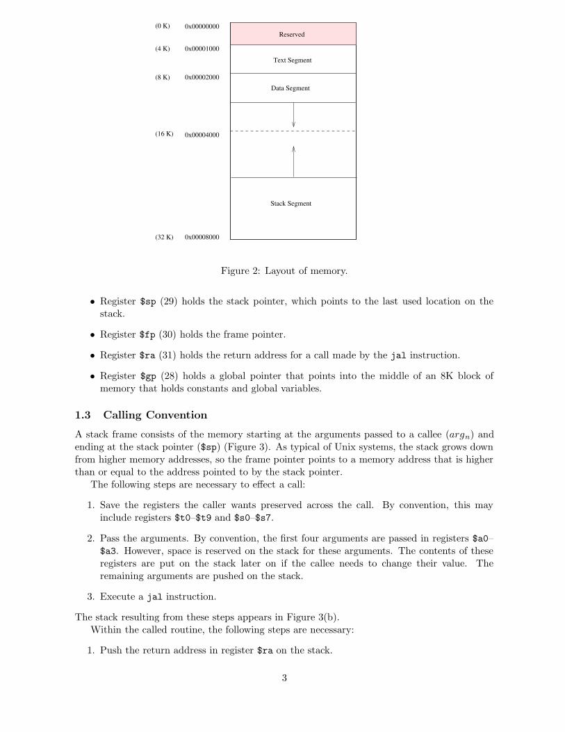
A program’s address space is composed of three parts (Figure 2).
• At the beginning of the user address space (0x00001000) is the text segment, which holdsthe instructions for a program.
• After the text segment is the data segment (starting at 0x00002000), which is divided intotwo parts.
– Static data – objects whose size and address are known to the compiler and linker.
– Dynamic data – objects for which space is allocated at run time.
• The stack segment resides at the end of the address space (0x00008000). It grows towardsthe data segment.
1

PC
Hi
CPU Coprocessor 1 (FPU)
Coprocessor 0
Memory
Registers
$0
$31
. . .
ArithmeticFP Unit
(exceptions and memory)
Registers
$0
$31
. . .
Lo
ALU MultiplyDivide
Figure 1: MIPS R2000 CPU and FPU.
1.2 CPU Registers
The MIPS central processing unit contains 32 general purpose registers that are numbered 0–31. Register n is designated by $n. Register $0 always contains the hardwired value 0. MIPShas established a set of conventions as to how registers should be used. These suggestions areguidelines, which are not enforced by the hardware. Table 1 lists the registers and describestheir intended use. A register may be addressed either by its name or by its number.
• Registers $at (1), $k0 (26), and $k1 (27) are reserved for use by the assembler and oper-ating system.
• Registers $a0–$a3 (4–7) are used to pass the first four arguments to routines (remainingarguments are passed on the stack).
• Registers $v0 and $v1 (2, 3) are used to return values from functions.
• Registers $t0–$t9 (8–15, 24, 25) are caller-saved registers used for temporary quantitiesthat do not need to be preserved across calls.
• Registers $s0–$s7 (16–23) are callee-saved registers that hold long-lived values that shouldbe preserved across calls.
2
Reserved
Text Segment
0x00001000(4 K)
0x00000000(0 K)
0x00008000(32 K)
0x00002000(8 K)
Data Segment
0x00004000(16 K)
Stack Segment
Figure 2: Layout of memory.
• Register $sp (29) holds the stack pointer, which points to the last used location on thestack.
• Register $fp (30) holds the frame pointer.
• Register $ra (31) holds the return address for a call made by the jal instruction.
• Register $gp (28) holds a global pointer that points into the middle of an 8K block ofmemory that holds constants and global variables.
1.3 Calling Convention
A stack frame consists of the memory starting at the arguments passed to a callee (argn) andending at the stack pointer ($sp) (Figure 3). As typical of Unix systems, the stack grows downfrom higher memory addresses, so the frame pointer points to a memory address that is higherthan or equal to the address pointed to by the stack pointer.
The following steps are necessary to effect a call:
1. Save the registers the caller wants preserved across the call. By convention, this mayinclude registers $t0–$t9 and $s0–$s7.
2. Pass the arguments. By convention, the first four arguments are passed in registers $a0–$a3. However, space is reserved on the stack for these arguments. The contents of theseregisters are put on the stack later on if the callee needs to change their value. Theremaining arguments are pushed on the stack.
3. Execute a jal instruction.
The stack resulting from these steps appears in Figure 3(b).Within the called routine, the following steps are necessary:
1. Push the return address in register $ra on the stack.
3

......
old localvariables
saved regsto restoreon return
localvariables
OldStackframe
OldStackframe
localvariables
OldStackframe
Stackframe
New
Stackframe
New
saved regsto restoreon return
...
Stack prior to saving registers
and pushing parameters onto stack
(a) Stack after procedure entry
New frame established
(c)
Parameters pushed onto stack
Stack prior to procedure entry(b)
return address
original frame pointer
... ...
return address
original frame pointer
arg n
arg n-1
...
arg 1
arg 2
...
saved register x
saved register y
return address
original frame pointer
arg n
arg n-1
arg 1
arg 2
saved register x
saved register y
return address
last local variable
first local variable
old frame pointer
...
...
...
...
Stack start Stack start Stack start
Address 0 Address 0 Address 0
$fp
$sp
$sp
$fp
$sp
$fp
Figu
re3:
Layou
tof
astack
frame.
The
frame
poin
terpoin
tsto
the
oldfram
epoin
tersaved
onth
estack
.T
he
stackpoin
terpoin
tsto
the
lastw
ordin
the
frame.
4

Register Name Number Usage
zero 0 Constant 0at 1 Reserved for assemblerv0 2 Expression evaluation andv1 3 results of a functiona0 4 Argument 1a1 5 Argument 2a2 6 Argument 3a3 7 Argument 4t0 8 Temporary (not preserved across call)t1 9 Temporary (not preserved across call)t2 10 Temporary (not preserved across call)t3 11 Temporary (not preserved across call)t4 12 Temporary (not preserved across call)t5 13 Temporary (not preserved across call)t6 14 Temporary (not preserved across call)t7 15 Temporary (not preserved across call)s0 16 Saved temporary (preserved across call)s1 17 Saved temporary (preserved across call)s2 18 Saved temporary (preserved across call)s3 19 Saved temporary (preserved across call)s4 20 Saved temporary (preserved across call)s5 21 Saved temporary (preserved across call)s6 22 Saved temporary (preserved across call)s7 23 Saved temporary (preserved across call)t8 24 Temporary (not preserved across call)t9 25 Temporary (not preserved across call)k0 26 Reserved for OS kernelk1 27 Reserved for OS kernelgp 28 Pointer to global areasp 29 Stack pointerfp 30 Frame pointerra 31 Return address (used by function call)
Table 1: MIPS registers and the convention governing their use.
2. Push the old frame pointer (currently in register $fp) on the stack.
3. Assign the current top-of-stack address to the frame pointer (in register $fp).
4. Allocate on the stack space for local variables by subtracting the number of words theyrequire from the stack pointer, and assigning the result to register $sp.
The stack resulting from these steps appears in Figure 3(c).Finally, to return from a call, a function executes the following steps:
1. Place the returned value into $v0 (and $v1 if necessary).
2. Restore to register $ra the return address which is stored in memory location $fp + 4.
3. Pop the stack by assigning $fp + 8 to register $sp. This points the stack pointer to thememory location of arg1.
4. Restore the frame pointer in register $fp by assigning to it the old value of the framepointer, which resides in the memory location stored in register $fp.
5

5. Return by jumping to the address in register $ra.
Now we have returned to the calling program, which performs the following steps:
1. Pop the arguments off the stack by making the stack pointer point to the last saved register.
2. Restore any registers that were saved upon entry, and pop the stack to the original position.
The stack resulting from these steps appears in Figure 3(a).
2 SPIM
SPIM S20 is a simulator that runs programs for the MIPS R2000/R3000 RISC.1 SPIM can readand immediately execute files containing assembly language or MIPS executable files. SPIM isa self-contained system for running these programs and contains a debugger and interface to afew operating system services.
You can download the SPIM simulator from: http://www.cs.wisc.edu/~larus/spim.html
2.1 Why Use a Simulator?
An obvious question is: why use a simulator when many people have workstations that containa hardware, and hence significantly faster, implementation of this computer? One reason isthat these workstations are not generally available. Another reason is that these machines willnot persist for many years because of the rapid progress leading to new and faster computers.Unfortunately, the trend is to make computers faster by executing several instructions concur-rently, which makes their architecture more difficult to understand and program. The MIPSarchitecture represents a simple, clean RISC machine.
In addition, simulators can provide a better environment for low-level programming than anactual machine because they can detect more errors and provide more features than an actualcomputer. For example, SPIM has an X-window interface that is better than most debuggersfor the actual machines.
Finally, simulators are a useful tool for studying computers and the programs that run onthem. Because they are implemented in software, not silicon, they can be easily modified to addnew instructions, build new systems such as multiprocessors, or simply to collect data.
2.2 SPIM Interface
To run SPIM in Linux you need to simply type xspim; in Windows click on PCSpim.The Linux version of SPIM has five panes (Figure 4). The Windows version has four panes;
the control buttons in the second Linux pane described below appear in a drop-down menu fromthe Simulator label (top of the window).
The top pane displays the contents of the registers. It is continually updated, except whilea program is running.
The next pane in the Linux version contains the buttons that control the simulator (drop-down menu in Windows):
quit
Exit from the simulator.
load
Read an assembly language file into memory.
1For a description of the real machines, see Gerry Kane and Joe Heinrich, MIPS RISC Architecture, Prentice
Hall, 1992.
6

Figure 4: X Windows interface to SPIM.
7

reload
Reinitialize memory and registers, and read the previously loaded file into memory.
run
Start the program running.
step
Step through a program (each step may be composed of one or more instructions).
clear
Reinitialize registers or memory.
set value
Set the value in a register or memory location.
Print the value in a register or memory location.
breakpoint
Set or delete a breakpoint or list all breakpoints.
help
Print a help message.
terminal
Raise or hide the console window.
mode
Set SPIM operating modes. The quiet mode does not report exceptions. The bare modedoes not provide the additional addressing modes provided by the assembler (Table 3).
The next two panes display the memory contents. The top one shows instructions from theuser and kernel text segments.2 The first few instructions in the text segment are startup code.
The lower of these two panes displays the data and stack segments. Both panes are updatedas a program executes.
The bottom pane is used to display messages from the simulator. It does not display outputfrom an executing program. When a program reads or writes, its I/O appears in a separatewindow, called Console, which pops up when needed.
2.3 Assembler Syntax
Comments in assembler files begin with a sharp-sign (#). Everything from the sharp-sign tothe end of the line is ignored.
Identifiers are a sequence of alphanumeric characters, underbars ( ) and dots (.) that do notbegin with a number.
Operation codes (opcodes) for instructions are reserved words that are not valid identifiers(the Appendix has a list of these opcodes).
Labels are declared by putting them at the beginning of a line followed by a colon.
The code is divided into two segments .data and .text. The first instruction in the .text
segment must be labelled main.
2Each source instruction appears as a comment on the first instruction to which it is translated.
8

Service Call Code Arguments Result
print int 1 $a0 = integerread int 5 integer (in $v0)exit 10
Table 2: System services.
Example:
.data # indicates the beginning of the data
item: .word 1 # stores the number 1 in a memory word labelled "item"
.text # indicates the beginning of the program
main: lw $t0, item # load the word in item into register $t0
SPIM supports a subset of the assembler directives provided by the MIPS assembler:
.asciiz str
Store the string in memory and null-terminate it.
.byte b1, ..., bn
Store the n values in successive bytes of memory.
.data <addr>
The following data items should be stored in the data segment. If the optional argumentaddr is present, the items are stored beginning at address addr .
.space n
Allocate n bytes of space in the current segment (which must be the data segment inSPIM).
.text <addr>
The next items are put in the user text segment. In SPIM, these items may only beinstructions or words (see the .word directive below). If the optional argument addr ispresent, the items are stored beginning at address addr .
.word w1, ..., wn
Store the n 32-bit quantities in successive memory words.
2.4 System Calls
SPIM provides a small set of operating-system-like services through the system call (syscall)instruction. To request a service
1. put the system call code (Table 2) in register $v0, and
2. put the argument(s) in register $a0, and $a1 if necessary.
System calls that return values put their result in register $v0.
print int is passed an integer (in $a0) and prints it on the console.
read int reads an entire line of input up to and including the newline. Characters followingthe number are ignored. The result is placed in $v0.
exit stops a program from running.
9

3 Very Reduced Instruction Set
In all the instructions below, Rsrci is a register, and Imm an immediate value (a 16 bit integer).
3.1 Arithmetic Instructions
add Rdest, Rsrc1, Rsrc2 Addition (with overflow)addi Rdest, Rsrc1, Imm Addition Immediate (with overflow)Put the sum of the integers from register Rsrc1 and Rsrc2 (or Imm) into register Rdest.
div Rsrc1, Rsrc2 Divide (with overflow)Divide the contents of register Rsrc1 by those of Rsrc2. Leave the quotient in register Lo andthe remainder in register Hi. If an operand is negative, the result is unspecified in SPIM, anddepends on the machine on which SPIM is run.
mult Rsrc1, Rsrc2 MultiplyMultiply the contents of the two registers. Leave the low-order word of the product in registerLo and the high-order word in register Hi.
sub Rdest, Rsrc1, Rsrc2 Subtract (with overflow)Put the difference of the integers from register Rsrc1 and Rsrc2 into register Rdest.
3.2 Data Movement Instructions
The multiply and divide instructions put their result in two additional registers, Hi and Lo. Thefollowing instructions move values from these registers.
mfhi Rdest Move From Himflo Rdest Move From LoMove the contents of the Hi (Lo) register to register Rdest.
3.3 Logical Instructions
and Rdest, Rsrc1, Rsrc2 ANDandi Rdest, Rsrc1, Imm AND ImmediatePut the logical AND of the integers from register Rsrc1 and Rsrc2 (or Imm) into register Rdest.
nor Rdest, Rsrc1, Rsrc2 NORPut the logical NOR of the integers from register Rsrc1 and Rsrc2 into register Rdest.
or Rdest, Rsrc1, Rsrc2 ORori Rdest, Rsrc1, Imm OR ImmediatePut the logical OR of the integers from register Rsrc1 and Rsrc2 (or Imm) into register Rdest.
xor Rdest, Rsrc1, Rsrc2 XORxori Rdest, Rsrc1, Imm XOR ImmediatePut the logical XOR of the integers from register Rsrc1 and Rsrc2 (or Imm) into register Rdest.
10
Format Address Computation
(register) contents of registerImm immediate (actual value)[−]Imm(register) [−]immediate + contents of registersymbol address of symbolsymbol+[−]Imm address of symbol + [−]immediatesymbol+[−]Imm(register) { address of symbol + contents of register } + [−]immediate
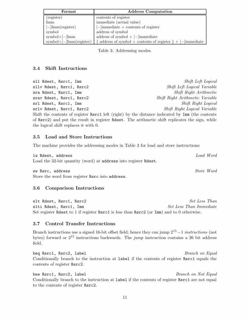
Table 3: Addressing modes.
3.4 Shift Instructions
sll Rdest, Rsrc1, Imm Shift Left Logicalsllv Rdest, Rsrc1, Rsrc2 Shift Left Logical Variablesra Rdest, Rsrc1, Imm Shift Right Arithmeticsrav Rdest, Rsrc1, Rsrc2 Shift Right Arithmetic Variablesrl Rdest, Rsrc1, Imm Shift Right Logicalsrlv Rdest, Rsrc1, Rsrc2 Shift Right Logical VariableShift the contents of register Rsrc1 left (right) by the distance indicated by Imm (the contentsof Rsrc2) and put the result in register Rdest. The arithmetic shift replicates the sign, whilethe logical shift replaces it with 0.
3.5 Load and Store Instructions
The machine provides the addressing modes in Table 3 for load and store instructions:
lw Rdest, address Load WordLoad the 32-bit quantity (word) at address into register Rdest.
sw Rsrc, address Store WordStore the word from register Rsrc into address.
3.6 Comparison Instructions
slt Rdest, Rsrc1, Rsrc2 Set Less Thanslti Rdest, Rsrc1, Imm Set Less Than ImmediateSet register Rdest to 1 if register Rsrc1 is less than Rsrc2 (or Imm) and to 0 otherwise.
3.7 Control Transfer Instructions
Branch instructions use a signed 16-bit offset field; hence they can jump 215−1 instructions (notbytes) forward or 215 instructions backwards. The jump instruction contains a 26 bit addressfield.
beq Rsrc1, Rsrc2, label Branch on EqualConditionally branch to the instruction at label if the contents of register Rsrc1 equals thecontents of register Rsrc2.
bne Rsrc1, Rsrc2, label Branch on Not EqualConditionally branch to the instruction at label if the contents of register Rsrc1 are not equalto the contents of register Rsrc2.
11
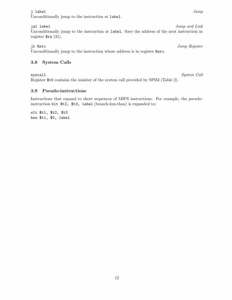
j label JumpUnconditionally jump to the instruction at label.
jal label Jump and LinkUnconditionally jump to the instruction at label. Save the address of the next instruction inregister $ra (31).
jr Rsrc Jump RegisterUnconditionally jump to the instruction whose address is in register Rsrc.
3.8 System Calls
syscall System CallRegister $v0 contains the number of the system call provided by SPIM (Table 2).
3.9 Pseudo-instructions
Instructions that expand to short sequences of MIPS instructions. For example, the pseudo-instruction blt $t2, $t3, label (branch-less-than) is expanded to:
slt $t1, $t2, $t3
bne $t1, $0, label
12

Appendix: Opcodes (Cannot be Used as Labels)
Common Opcodes
.align .ascii .asciiz .data .byte .double
.end .extern .float .globl .text .wordadd addi addiu addu and andib bal beq bge bgeu bgezbgezal bgt bgtu ble bleu blezblt bltu bltz bne bnez breakdiv divu j jal jalr jrla lb lbu ld lh lhului lw lwl lwr mfhi mflomul mult neg negu nop noror ori rem remu rol sbsd seq sge sgt sgtu shsle sleu sll slt slti sltiusltu sne sra srav srl srlvsub subu sw swl swr syscallusw xor xori
Unusual Opcodes
.asm0 .bgnb .endb .endr .ent .file
.fmask .frame .kdata .ktext .lab .lcomm
.livereg .loc .noalias .option .rdata .repeat
.sdata .set .struct .verstamp .vregabs abs.s add.d add.s bc0f bc0tbc1t bc2f bc2t bc3f bc3t c.eq.dc.eq.s c.f.d c.le.d c.le.s c.lt.d c.lt.sc.nge.d c.nge.s c.ngl.s c.ngle.d c.ngle.s c.ngt.dc.ngt.s c.ole.d c.olt.d c.olt.s c.seq.d c.seq.sc.sf.d c.sf.s c.ueq.s c.ule.d c.ule.s c.ult.dc.ult.s c.un.d cfc0 cfc1 cfc2 cfc3cop0 cop1 cop3 ctc0 ctc1 ctc2ctc3 cvt.d.s cvt.s.d cvt.s.w cvt.w.d cvt.w.sdiv.d l.d li.d li.s lwc0 lwc1lwc3 mfc0 mfc1 mfc1.d mfc2 mfc3mov.d mov.s mtc0 mtc1 mtc1.d mtc2mtc3 mthi mtlo mul.d mul.s mulomulou neg.d neg.s rfe s.d s.ssub.d sub.s swc0 swc1 swc2 swc3tlbp tlbr tlbwi tlbwr ulh ulhuush
13
Recommended


![Lidialetykarina pczombie,spim,ramsonware[1]](https://img.pdfslide.net/doc/110x75/55b4a040bb61ebaf168b4824/lidialetykarina-pczombiespimramsonware1.jpg)
