SPRINGBACK PREDICTION OF MILD STEEL SHEET ON L-BENDING
CHE AMIR RAJHAN BIN CHE JAFFAR
Report submitted in partial fulfillment of the requirement for the award of the degree of
Bachelor of Mechanical Engineering
Faculty of Mechanical Engineering UNIVERSITY MALAYSIA PAHANG
DECEMBER 2010
UNIVERSITI MALAYSIA PAHANG
FACULTY OF MECHANICAL ENGINEERING
We certify that the project entitled “Springback Prediction of Mild Steel on L-Bending”
is written by Che Amir Rajhan bin Che Jaffar. We have examined the final copy of this
project and in our opinion; it is fully adequate in terms of scope and quality for the
award of the degree of Bachelor of Engineering. We herewith recommend that it be
accepted in partial fulfillment of the requirements for the degree of Bachelor of
Mechanical Engineering.
Examiner Signature
ii
SUPERVISOR’S DECLARATION
I hereby declare that I have checked this project and in my opinion, this project is
adequate in terms of scope and quality for the award of the degree of Bachelor of
Mechanical Engineering.
Signature : ……………………………..
Name of Supervisor : MR JASRI BIN MOHAMAD
Position : LECTURER
Date : 06 DECEMBER 2010
iii
STUDENT’S DECLARATION
I hereby declare that the work in this project is my own except for quotations and
summaries which have been duly acknowledged. The project has not been accepted for
any degree and is not concurrently submitted for award of other degree.
Signature : ………………………………….
Name : CHE AMIR RAJHAN BIN CHE JAFFAR
ID Number : MA07068
Date : 06 DECEMBER 2010
v
ACKNOWLEDGEMENTS
I am grateful and would like to express my sincere appreciation to my main thesis supervisor, Mr. Jasri Bin Mohamad for his germinal ideas, invaluable guidance, continuous encouragement and constant support in making this research possible. He has always impressed me with his outstanding professional conduct, his strong conviction for science, and his belief that a bachelor program is only a start of a life-long learning experience. Without his continuous support and interest, I would not have been able to complete this final year project successfully. I also sincerely thanks for the time spent proofreading and correcting my many mistakes.
I am also indebted to Universiti Malaysia Pahang (UMP) for providing internet
and final year project lab facility. Special thanks also given to librarians UMP for their assistance in supplying the relevant literatures and are useful indeed. I acknowledge my sincere indebtedness and gratitude to my parents for their love, dream and sacrifice throughout my life. I am also grateful to my fellow members for their supportive and helps that were inevitable to make this work possible. I cannot find the appropriate words that could properly describe my appreciation for their devotion, support and faith in my ability to attain my goals. I would like to acknowledge their comments and suggestions, which was crucial for the successful completion of this study.
vi
ABSTRACT
This report deals with deformation analysis of springback in L-bending of sheet metal. Nowadays, many softwares is produced to investigate about the springback in sheet metal bending. These softwares is getting applicable and useful from time to time. Mastering this software will make the industry especially manufacturing industry know the element and condition of materials and appropriate bending process for such material in order to manage the company production cost. This report is done with simulation of springback using a material of Mild Steel on L-bending process and also an experiment of L-bending is conducted using a 1 mm thickness. The springback of Mild Steel sheet was investigated using finite element analysis. Abaqus software is used in this project to simulate the springback of sheet metal in L-bending. The value of 0.5 mm mesh is used for the simulation. In this simulation the die and pressure pad is declared as contact with the workpiece and friction was defined with 0.1. Punch is also declared as contact with the workpiece and it was defined as frictionless. Then the nodes were taken and import to Auto Cad software to measure the angle of springback from the simulation. An experiment of ten specimens of Mild Steel sheet were conducted in this experiment and the result were taken. Thickness of 1 mm was used for the experiment for all specimens. Profile Projector machine is used to measure the angle of the ten specimens. The result from the experiment will be compared to the result of simulation. The result of this report show the springback in simulation 2o and the result of experiment is 2.3o.

vii
ABSTRAK
Laporan ini berurusan dengan analisis pembentukan tentang bangkit kembali dalam L-bengkok dari lembaran logam. Pada masa ini, banyak perisian yang dihasilkan untuk menyiasat tentang lenturan dalam lembaran logam bengkokkan. Perisian ini semakin boleh di gunakan dan berguna dari semasa ke semasa. Menguasai perisian ini akan membuat industri terutama industri perkilangan mengetahui unsur dan keadaan bahan dan proses bengkokkan yang sesuai untuk bahan tersebut untuk menguruskan kos pengeluaran syarikat. Laporan ini disiapkan dengan simulasi tentang bangkit kembali menggunakan bahan Keluli Lembut dalam proses L-bengkok dan juga sebuah eksperimen L-bengkok dilakukan dengan menggunakan ketebalan 1 mm. Bangkit kembali kepingan Keluli Lembut diteliti menggunakan Analisis Unsur Terhingga. Perisian “ABAQUS” digunakan dalam projek ini untuk mensimulasikan lentur dari kepingan logam dalam L-bengkok. Nilai mesh 0.5mm digunakan untuk simulasi ini. Dalam simulasi ini pemati dan tekanan pad dinyatakan sebagai hubungan dengan benda kerja dan ditakrifkan gesekan dengan 0.1. Penekan juga dinyatakan sebagai hubungan dengan benda kerja dan ia ditakrifkan sebagai tiada geseran. Kemudian titik diambil dan dipindahkan ke perisian “Auto Cad” untuk mengukur sudut bangkit kembali dari simulasi. Sepuluh kepingan Mild Steel dilakukan dalam eksperimen ini dan hasilnya diambil. Ketebalan 1 mm digunakan dalam eksperimen ini untuk semua spesimen. “Profile Projector” mesin digunakan untuk mengukur sudut dari sepuluh spesimen itu. Hasil daripada eksperimen akan dibandingkan dengan hasil simulasi. Keputusan laporan ini menunjukkan 2° lentur daripada simulasi dan 2.3° lentur daripada eksperimen.
viii
TABLE OF CONTENT
Page
SUPERVISOR’S DECLARATION ii
STUDENT DECLARATION iii
DEDICATION iv
ACKNOWLEDGEMENTS v
ABSTRACT vi
ABSTRAK vii
TABLE OF CONTENT viii
LIST OF TABLES xi
LIST OF FIGURES xii
LIST OF SYMBOLS xii
LIST OF ABBREVIATIONS xiv
CHAPTER 1 INTRODUCTION
1.1 Introduction 1
1.2 Project Background 1
1.3 Problem Statement 2
1.4 Project Objectives 2
1.5 Project Scopes 3
1.6 Thesis Organization 3
CHAPTER 2 LITERATURE REVIEW
2.1 Introduction 4
2.2 Theory of Sheet Metal Bending 4
2.3 Types of Bending 5
2.4 L-Bending
2.4.1 Parameter of Bending
5
6
2.5 Base Equation of Bending Force 7
2.6 Stress-Strain Curve
2.6.1 Yield Point
8
8
ix
2.6.2 Ultimate Tensile Strenght 9
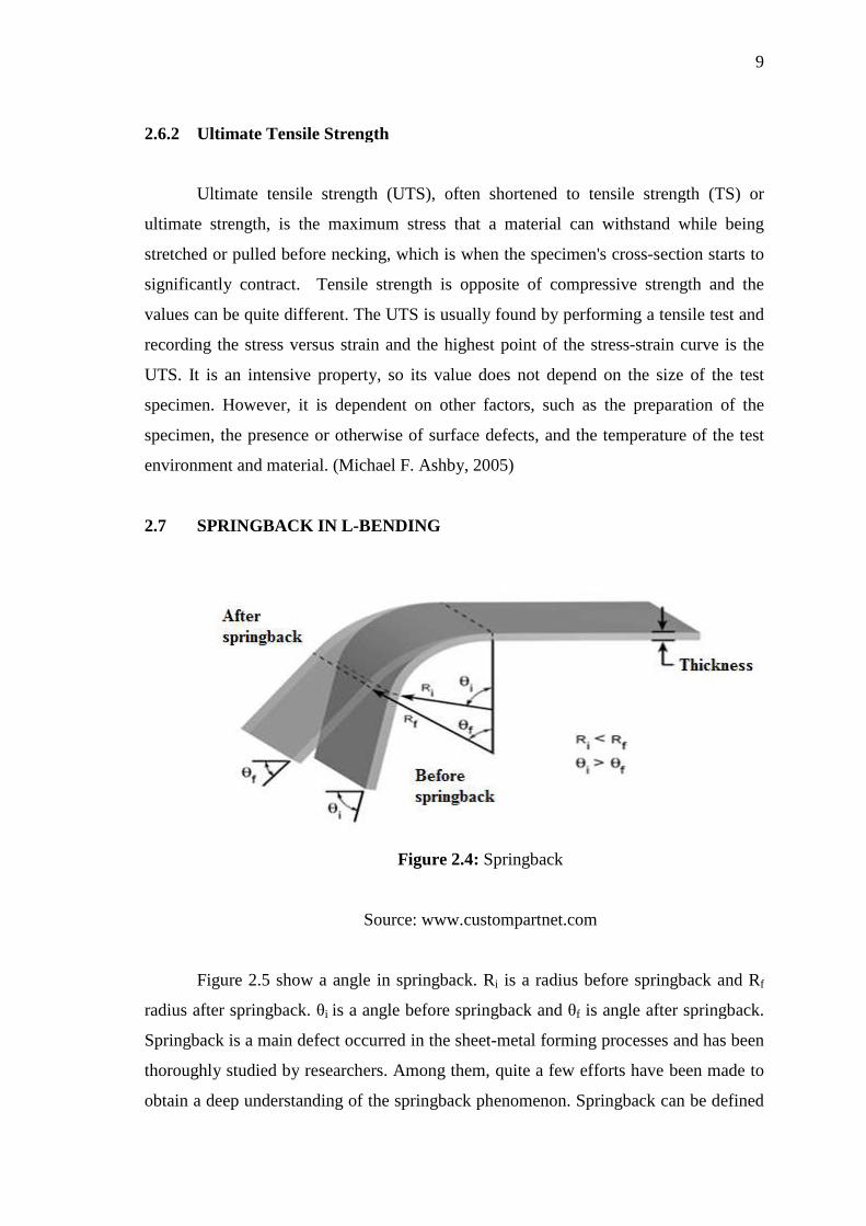
2.7 Springback in L-Bending 9
2.8 Finite Element Method
2.8.1 Isotropic Hardening Modelling 2.8.2 Plane Stress 2.8.3 Plane Strain 2.8.4 Boundary Condition 2.8.5 CQUAD4
10
11 13 13 14 14
2.10 Material
2.10.1 Low Carbon Steel 2.10.2 Aluminium Alloy 2.10.3 Stainless Steel
15
15 15 16
CHAPTER 3 METHODOLOGY
3.1 Introduction 17
3.2 Project Flow Chart 18
3.3 Bending Modeling 19
3.3.1 Punch 3.3.2 Die 3.3.3 Pressure Pad 3.3.4 Sheet Metal
19 20 21 22
3.4 Material and Properties Define
3.4.1 Elastic Properties Data 3.4.2 Plastic Properties Data 3.4.3 Mesh Size 3.4.4 Modelling Contact 3.4.5 Analysis and Evaluation
22
23 23 24 24 24
3.5 Experiment 25
CHAPTER 4 RESULTS AND DISCUSSION
4.1 Introduction 29
4.2 Simulation of the Sheet Metal Bending
4.1.1 Nodes Taken From Abaqus Software 4.1.2 Springback Result Using Auto Cad Software
29
32 33
x
4.3 Result From Experiment 35
4.4 Discussion 36
CHAPTER 5 CONCLUSION AND RECOMMENDATIONS
5.2 Conclusions 37
5.3 Recommendations 38
REFERENCES 39
APPENDICES
A1 Gant Chart for FYP 1 40
A2 Gant Chart for FYP 2 41
xi
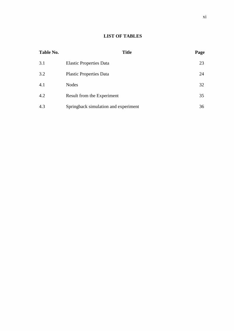
LIST OF TABLES
Table No. Title Page 3.1 Elastic Properties Data 23 3.2 Plastic Properties Data 24 4.1 Nodes 32 4.2 Result from the Experiment 35 4.3 Springback simulation and experiment 36
xii
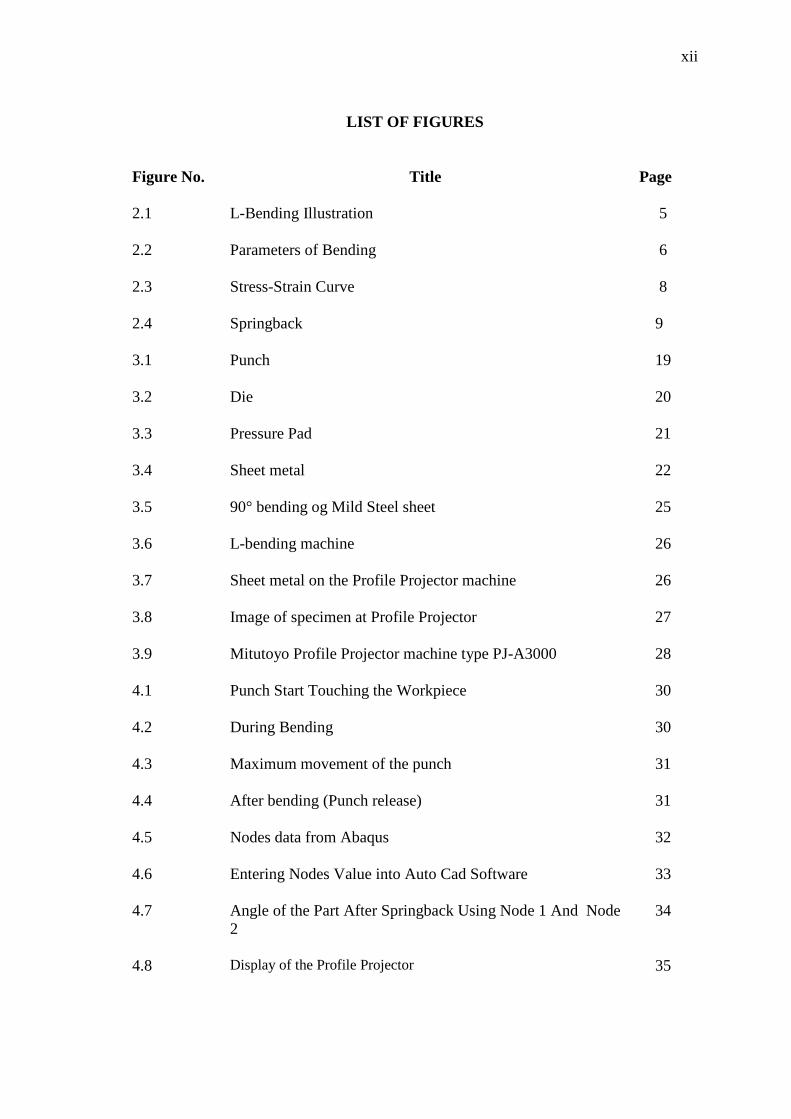
LIST OF FIGURES
Figure No. Title Page
2.1 L-Bending Illustration 5 2.2 Parameters of Bending 6 2.3 Stress-Strain Curve 8 2.4 Springback 9 3.1 Punch 19 3.2 Die 20 3.3 Pressure Pad 21 3.4 Sheet metal 22 3.5 90° bending og Mild Steel sheet 25 3.6 L-bending machine 26 3.7 Sheet metal on the Profile Projector machine 26 3.8 Image of specimen at Profile Projector 27 3.9 Mitutoyo Profile Projector machine type PJ-A3000 28 4.1 Punch Start Touching the Workpiece 30 4.2 During Bending 30 4.3 Maximum movement of the punch 31 4.4 After bending (Punch release) 31 4.5 Nodes data from Abaqus 32 4.6 Entering Nodes Value into Auto Cad Software 33 4.7 Angle of the Part After Springback Using Node 1 And Node
2 34
4.8 Display of the Profile Projector 35

xiii
LIST OF SYMBOLS
σ2 Variance
Fmax Bending Force
µ Mean

xiv
LIST OF ABBREAVIATION
FEA Finite Element Analysis
UTS Ultimate Tensile Strength
TS Tensile Strength
AISI American Iron and Steel Institute
CRES Called-Corrosion-Resistant
FYP Final Year Project
CHAPTER 1
INTRODUCTION
1.1 INTRODUCTION
This chapter provides a brief overview of the entire project consists of project
background, problem statement, objectives, scopes of the works and organization of the
thesis.
1.2 PROJECT BACKGROUND
This report deals with deformation analysis of springback in L-bending of sheet
metal. Nowadays, many softwares are produced to investigate about the springback in
sheet metal bending. These softwares are getting applicable and useful from time to
time. Mastering this software will make the industry especially manufacturing industry
know the element and condition of materials and appropriate bending process for such
material in order to manage the company production cost.
Abaqus software had been used for this project to simulate the springback of
sheet metal in L-bending. The model of experiment setup is draw in Abaqus software
and defined it as 2D. There have four main components in L-bending process. It is are
pressure pad, die, workpiece(sheet metal), and punch. The drawing of these tools is
depend on the actual geometry. After that, two nodes were taken from the simulation of
sheet metal. These nodes were export to the Auto Cad and the springback will be
measured.
2
Then, an experiment of L-bending will be conducted using bending machine.
Ten specimen were be using for the specimen. Specimen is measured using Profile
Projector machine to know the springback angle. The result from the experiment will be
compared to the result of simulation.
1.3 PROBLEM STATEMENT
Sheet metal stamping plays a major role in many industries today. As part
components get smaller and tolerances get tighter, the dimensional accuracy of a
stamped part becomes a crucial factor in determining the overall quality of the part. In
most, if not all, sheet metal forming processes, springback is the major problem faced.
Springback often complicates the design of forming dies, and final die designs may only
be accomplished after fabrication and testing of multiple prototypes. This poses
significant problems to designers, who must accurately assess the amount of springback
which occurs during a forming process so that a final desired part shape can be
obtained.
1.4 PROJECT OBJECTIVES
The objectives of this study are:
1. To evaluate accuracy in predicting springback using Finite Element Method
(FEA).
2. To apply FEA technology in sheet Mild Steel forming or bending.

3
1.5 PROJECT SCOPE
Basically, this analysis based on:
1. Geometrical models of 2D.
2. Numerical bending analysis based on Abaqus software.
3. To conduct experiment on sheet metal bending.
4. Analyze and compare the simulation and experiment result.
1.6 THESIS ORGANIZATION
This thesis consists of three 4 chapters:
Chapter 1 is provides a brief overview of the entire project include objective of
the project, scope and problem statement.
Chapter 2 is presents the background of the system including the types of
bending, parameters of bending, tolerances, springback ang the improvement of spring
back. It also discuss about bend allowance and material modeling.
Chapter 3 is discussing of methodology used for the application development. It
includes a flow chart of this report and the plan how to run the software to predict
springback.
Chapter 4 is discussing about a result from the simulation and the experiment. It
includes a how to calculates the springback by using a Auto Cad and calculation and
measuring of springback from experiment using Profile Projector PJ-A3000.
Chapter 5 is discussing about a conclusion and recommendation of this report. It
include a recommendation how to reduce a springback in L-bending.
CHAPTER 2
LITERATURE REVIEW
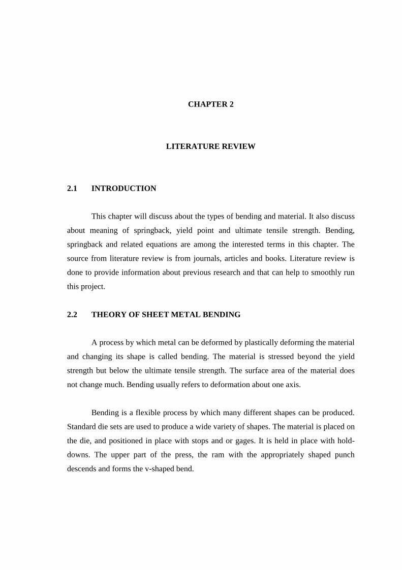
2.1 INTRODUCTION
This chapter will discuss about the types of bending and material. It also discuss
about meaning of springback, yield point and ultimate tensile strength. Bending,
springback and related equations are among the interested terms in this chapter. The
source from literature review is from journals, articles and books. Literature review is
done to provide information about previous research and that can help to smoothly run
this project.
2.2 THEORY OF SHEET METAL BENDING
A process by which metal can be deformed by plastically deforming the material
and changing its shape is called bending. The material is stressed beyond the yield
strength but below the ultimate tensile strength. The surface area of the material does
not change much. Bending usually refers to deformation about one axis.
Bending is a flexible process by which many different shapes can be produced.
Standard die sets are used to produce a wide variety of shapes. The material is placed on
the die, and positioned in place with stops and or gages. It is held in place with hold-
downs. The upper part of the press, the ram with the appropriately shaped punch
descends and forms the v-shaped bend.
Bending is done using Press Brakes. Press Brakes normally have a capacity of
20 to 200 tons to accommodate stock from 1m to 4.5m (3 feet to 15 feet). Larger and
smaller presses are used for specialized applications. Programmable back gages, and
multiple die sets available currently can make for a very economical process.
(Boljanovic, 2004)
2.3 TYPES OF BENDING
A bending tool must be decided depending on the shape and severity of bend.
Following are the different types of bending commonly used for precis
bending. (Boljanovic, 2004)
(a) "V" Bending
(b) "L" Bending
(c) "U" Bending
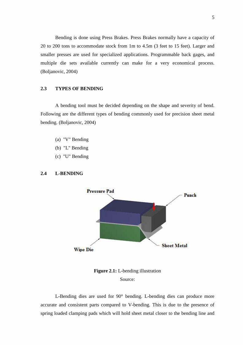
2.4 L-BENDING
L-Bending dies are used for 90° bending. L
accurate and consistent parts compared to V
spring loaded clamping pads which will hold sheet metal closer to the bending line and
Bending is done using Press Brakes. Press Brakes normally have a capacity of
20 to 200 tons to accommodate stock from 1m to 4.5m (3 feet to 15 feet). Larger and
smaller presses are used for specialized applications. Programmable back gages, and
e sets available currently can make for a very economical process.
TYPES OF BENDING
A bending tool must be decided depending on the shape and severity of bend.
Following are the different types of bending commonly used for precis
(Boljanovic, 2004)
(a) "V" Bending
(b) "L" Bending
(c) "U" Bending
Figure 2.1: L-bending illustration
Source:
ies are used for 90° bending. L-bending dies can
consistent parts compared to V-bending. This is due to the presence of
spring loaded clamping pads which will hold sheet metal closer to the bending line and
5
Bending is done using Press Brakes. Press Brakes normally have a capacity of
20 to 200 tons to accommodate stock from 1m to 4.5m (3 feet to 15 feet). Larger and
smaller presses are used for specialized applications. Programmable back gages, and
e sets available currently can make for a very economical process.
A bending tool must be decided depending on the shape and severity of bend.
Following are the different types of bending commonly used for precision sheet metal
bending dies can produce more
bending. This is due to the presence of
spring loaded clamping pads which will hold sheet metal closer to the bending line and

then the bending punch pushes the sheet metal into the bending die alon
line. L bending dies can also be used for bending angles smaller than 90° by providing
suitable punch profiles and by controlling the travel of the p
of L-bending operations to be done in a
complex parts. Figure 2.2 shows L
2.4.1 Parameter of Bending
1. Bend Allowance
axis.
2. Bend Angle – The included angle of the arc formed by the bending operation.
3. Bend Compensation
compressed by the bending o
occur in the
4. Bend Lines – The straight lines on the inside and outside surfaces of the
material where the flange boundary meets the bend area.
5. Inside Bend Radius
area.
then the bending punch pushes the sheet metal into the bending die alon
line. L bending dies can also be used for bending angles smaller than 90° by providing
suitable punch profiles and by controlling the travel of the punch. We may need a series
bending operations to be done in a progressive metal stamping die
Figure 2.2 shows L-bending illustration. (Boljanovic, 2004)
ending
Figure 2.2: Parameters of Bending
Source: www.custompartnet.com
Bend Allowance – The length of the arc through the bend area at the neutral
The included angle of the arc formed by the bending operation.
Bend Compensation – The amount by which the material is stretched or
compressed by the bending operation. All stretch or compression is assumed to
bend area.
The straight lines on the inside and outside surfaces of the
where the flange boundary meets the bend area.
end Radius – The radius of the arc on the inside surface of the bend
6
then the bending punch pushes the sheet metal into the bending die along the bending
line. L bending dies can also be used for bending angles smaller than 90° by providing
unch. We may need a series
progressive metal stamping die to produce
, 2004)
The length of the arc through the bend area at the neutral
The included angle of the arc formed by the bending operation.
The amount by which the material is stretched or
peration. All stretch or compression is assumed to
The straight lines on the inside and outside surfaces of the
The radius of the arc on the inside surface of the bend
7
6. K-factor – Defines the location of the neutral axis. It is measured as the
distance from the inside of the material to the neutral axis divided by the
material thickness.
7. Mold Lines – For bends of less than 180 degrees, the mold lines are the straight
lines where the surfaces of the flange bounding the bend area intersect. This
occurs on both the inside and outside surfaces of the bend.
8. Neutral Axis – Looking at the cross section of the bend, the neutral axis is the
theoretical location at which the material is neither compressed nor stretched.
9. Set Back - For bends of less than 180 degrees, the set back is the distance from
the bend lines to the mold line. (Boljanovic, 2004)
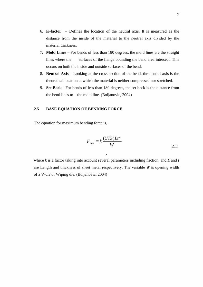
2.5 BASE EQUATION OF BENDING FORCE
The equation for maximum bending force is,
W
LtUTSkF
2
max
)(= (2.1)
,
where k is a factor taking into account several parameters including friction, and L and t
are Length and thickness of sheet metal respectively. The variable W is opening width
of a V-die or Wiping die. (Boljanovic, 2004)
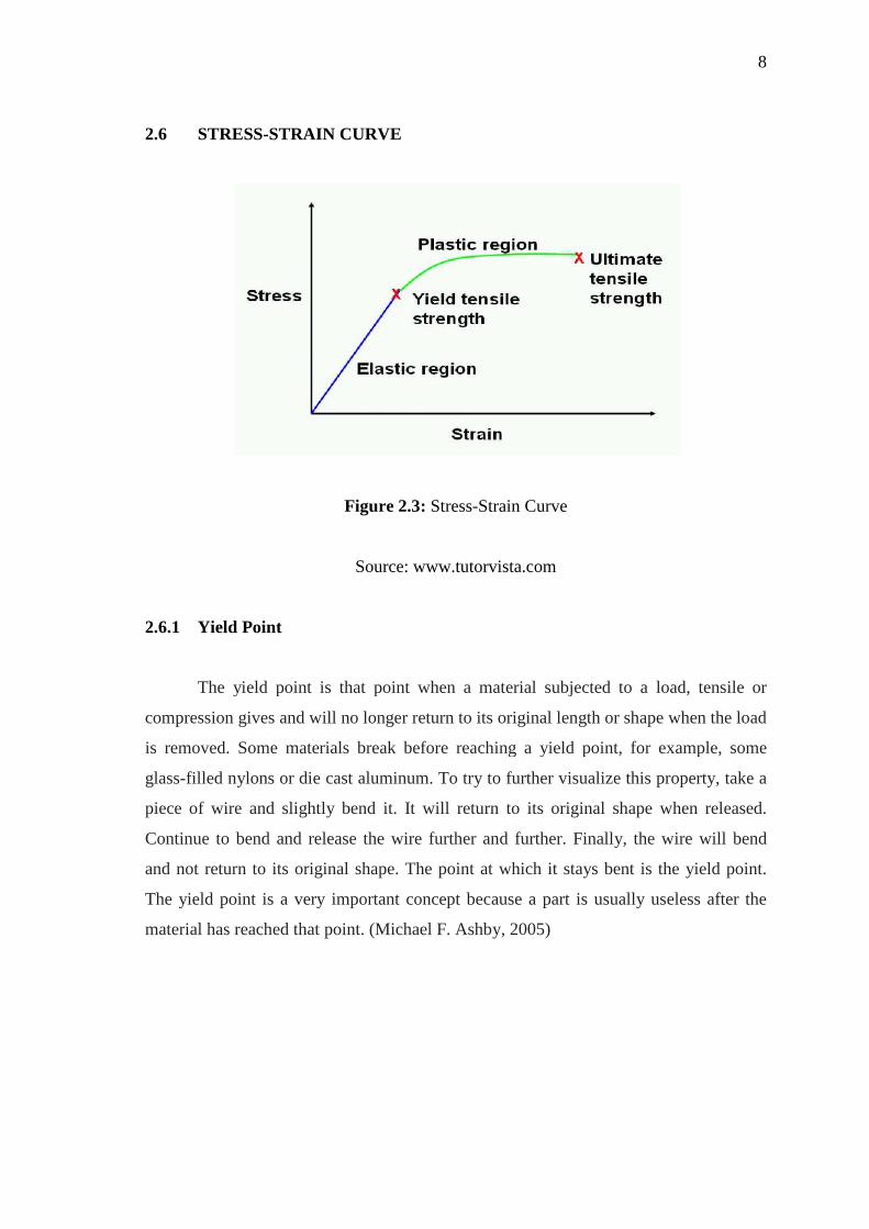
2.6 STRESS-STRAIN CURVE
2.6.1 Yield Point
The yield point is that point when a material subjected to a load, tensile or
compression gives and will no longer return to its original length or shape when the load
is removed. Some materials break before reaching a yield point, for example, some
glass-filled nylons or die cast aluminum. To try to further visualize this property, take a
piece of wire and slightly bend it. It will return to its original shape when released.
Continue to bend and release the wire further and further. Finally, the wire will bend
and not return to its original shape. The point at which it stays bent is the yield point.
The yield point is a very important concept because a part is usually useless a
material has reached that point.
STRAIN CURVE
Figure 2.3: Stress-Strain Curve
Source: www.tutorvista.com
The yield point is that point when a material subjected to a load, tensile or
compression gives and will no longer return to its original length or shape when the load
ved. Some materials break before reaching a yield point, for example, some
filled nylons or die cast aluminum. To try to further visualize this property, take a
piece of wire and slightly bend it. It will return to its original shape when released.
ontinue to bend and release the wire further and further. Finally, the wire will bend
and not return to its original shape. The point at which it stays bent is the yield point.
The yield point is a very important concept because a part is usually useless a
material has reached that point. (Michael F. Ashby, 2005)
8
The yield point is that point when a material subjected to a load, tensile or
compression gives and will no longer return to its original length or shape when the load
ved. Some materials break before reaching a yield point, for example, some
filled nylons or die cast aluminum. To try to further visualize this property, take a
piece of wire and slightly bend it. It will return to its original shape when released.
ontinue to bend and release the wire further and further. Finally, the wire will bend
and not return to its original shape. The point at which it stays bent is the yield point.
The yield point is a very important concept because a part is usually useless after the
2.6.2 Ultimate Tensile Strength
Ultimate tensile strength
ultimate strength, is the maximum
stretched or pulled before
significantly contract.
values can be quite different.
recording the stress versus
UTS. It is an intensive property
specimen. However, it is dependent on other factors, such as the preparation of the
specimen, the presence or otherwise of surface defects, and the temperature of the test
environment and material.
2.7 SPRINGBACK
Figure 2.5 show a angle in springback. R
radius after springback.
Springback is a main defect occurred in the sheet
thoroughly studied by researchers. Among them, quite a few efforts have been made to
obtain a deep understanding of the springback phenomenon. Springback can be defined
Ultimate Tensile Strength
Ultimate tensile strength (UTS), often shortened to tensile strength
, is the maximum stress that a material can withstand while being
stretched or pulled before necking, which is when the specimen's cross
Tensile strength is opposite of compressive strength
values can be quite different. The UTS is usually found by performing a
recording the stress versus strain and the highest point of the stress
intensive property, so its value does not depend on the size of the test
specimen. However, it is dependent on other factors, such as the preparation of the
specimen, the presence or otherwise of surface defects, and the temperature of the test
environment and material. (Michael F. Ashby, 2005)
INGBACK IN L-BENDING
Figure 2.4: Springback
Source: www.custompartnet.com
Figure 2.5 show a angle in springback. Ri is a radius before
. θi is a angle before springback and θf is angle after springback.
is a main defect occurred in the sheet-metal forming processes and has been
thoroughly studied by researchers. Among them, quite a few efforts have been made to
obtain a deep understanding of the springback phenomenon. Springback can be defined
9
tensile strength (TS) or
that a material can withstand while being
cross-section starts to
compressive strength and the
The UTS is usually found by performing a tensile test and
stress-strain curve is the
on the size of the test
specimen. However, it is dependent on other factors, such as the preparation of the
specimen, the presence or otherwise of surface defects, and the temperature of the test
is a radius before springback and Rf
is angle after springback.
metal forming processes and has been
thoroughly studied by researchers. Among them, quite a few efforts have been made to
obtain a deep understanding of the springback phenomenon. Springback can be defined

10
as an elastically-driven change of shape of the deformed part upon removal of external
loads. This phenomenon results in a deviation of the real product geometry from that
defined in the design phase and can cause significant problems during assembly. To
keep the product development time and manufacturing costs low, finite element analysis
aims to provide reliable information necessary for the modification of tool and product
geometry. Therefore, the accuracy of information obtained in a numerical simulation of
springback is essential for the product designers and die makers.
Springback is generally defined as the additional deformation of a structural
component, after the removal of forming loads. It is agreed in the literature that the
three main variables that influence springback are the geometry, manufacturing process
and blank material. Because of the extensive applications of high strength steels, the
significance of springback related problems has increased (Schrader, 2000).
2.8 FINITE ELEMENT ANALYSIS
FEA consists of a computer model of a material or design that is stressed and
analyzed for specific results. It is used in new product design, and existing product
refinement. A company is able to verify a proposed design will be able to perform to the
client's specifications prior to manufacturing or construction. Modifying an existing
product or structure is utilized to qualify the product or structure for a new service
condition. In case of structural failure, FEA may be used to help determine the design
modifications to meet the new condition.(Lakshmi, 2009)
There are generally two types of analysis that are used in industry: 2-D
modeling, and 3-D modeling. While 2-D modeling conserves simplicity and allows the
analysis to be run on a relatively normal computer, it tends to yield less accurate results.
3-D modeling, however, produces more accurate results while sacrificing the ability to
run on all but the fastest computers effectively. Within each of these modeling schemes,
the programmer can insert numerous algorithms (functions) which may make the
system behave linearly or non-linearly. Linear systems are far less complex and
generally do not take into account plastic deformation. Non-linear systems do account
Recommended