STATOR RESISTANCE ESTIMATION OF INDUCTION MOTOR USING
GENETIC ALGORITHM
NURUL SYAMILA BINTI MOHD ROSLI
This thesis is submitted as partial fulfillment of the requirements for the award of the
Bachelor of Electrical Engineering (Power System)
Faculty of Electrical And Electronics Engineering
University Malaysia Pahang
JUNE 2012

vi
ABSTRACT
Nowadays, induction motors are mainly used in all industrial especially in plant
industrial. In general, this motor is widely used because it is cheaper, easy to
maintenance, no friction by brushes and their speed are easy to control compared to
the direct current (DC) motor. But, the stator resistance changes continuously with
the temperature of the machine. The changes can cause an error between the actual
and estimated motor torques which leads to motor break down in worst cases. In
order to solve this issue, a genetic algorithm method is designed to estimate the
variation of stator resistance. This project is about to design genetic algorithm
estimator using MATLAB software, and builds an actual induction motor using
Newcastle University Drives Simulation Library. Finally these parts of Simulink
diagram will be combined to estimate the variation of stator resistance.

vii
ABSTRAK
Pada masa kini motor induksi kebanyakannya digunakan dalam semua industri
terutama di loji perindustrian. Secara amnya, motor ini digunakan secara meluas
kerana ia lebih murah, mudah dengan kerja penyelengaraan, tiada geseran oleh berus
dan kelajuan mereka mudah dikawal berbanding dengan motor arus terus. Tetapi
rintangan menukar secara berterusan dengan suhu mesin. Perubahan boleh
menyebabkan ralat antara daya kilas motor sebenar dengan anggaran yang akan
menyebabkan motor rosak teruk. Dalam usaha untuk menyelesaikan isu ini, satu
kaedah algoritma genetik telah direka untuk menganggarkan perubahan rintangan
pemegun. Projek ini adalah untuk merekabentuk algoritma genetik penganggar
menggunakan perisian MATLAB dan membina sebuah model motor induksi
menggunakan pemacu simulasi perpustakaan Universiti Newcastle. Akhirnya semua
simulasi ini akan digabungkan untuk menganggarkan perubahan rintangan pemegun.
viii
TABLE OF CONTENT
CHAPTER TITLE PAGE
DECLARATION ii
ACKNOWLEDGEMENT iii
ABSTRACT iv
ABSTRAK v
TABLE OF CONTENTS vi
LIST OF TABLES ix
LIST OF FIGURES x
1 INTRODUCTION
1.1 Overview 1
1.2 Objectives 3
1.3 Scopes Of Project 3
1.4 Problem Statement 3
2 LITERATURE REVIEW
2.1 Introduction 4
2.1.1 Estimation of stator resistance of induction
motor for direct torque
4
2.1.2 A fuzzy logic approach for stator resistance
estimation of an induction motor
5

x
2.1.3Resistance estimation for temperature
determination in PMSMs through signal
injection.
6
2.1.4 Design optimization of induction motor by
genetic algorithm and comparison with
existing motor
6
2.1.5 Electrical energy consumption estimation by
genetic algorithm and analysis of variance
7
2.1.6 Application of genetic algorithm to the
optimization of a roll type electrostatic
separation process
8
3 METHODOLOGY
3.1 Introduction 9
3.2 Simulation Diagram Of Induction Motor Without
Load Using Newcastle Library
11
3.3 Simulation Diagram Of Induction Motor With Load
Using Newcastle Library
13
3.4 Simulation Diagram Of Induction Motor By Using
MATLAB Simulink
15
3.5 Simple estimating by using Proportional Integral
(PI).
19
3.6 Estimator by using Genetic Algorithm 20
4 RESULT AND ANALYSIS
4.1 Simulation Of Induction Motor Without Load Using
Newcastle Library
22
4.2 Simulation Of Induction Motor With Load Using
Newcastle Library
26
4.3 Simulation of Induction Motor By Using MATLAB
Simulink
30
4.4 PI estimator 35

xi
5 CONCLUSION AND RECCOMMENDATION
5.1 Conclusion 37
5.2 Future Recommendation 38
REFERENCES 39
APPENDIX

xi
LIST OF TABLES
TABLE TITLE PAGE
3.1 Parameter of induction motor without load 12
3.2 Parameter of induction motor with load 13
=

xii
LIST OF FIGURES
FIGURES TITLE PAGE
3.1 Block diagram for overall system 9
3.2 An induction motor model without load using
NUDSL
11
3.3 Induction motor model with load using
NUDSL
13
3.4 The combination of both machine 15
3.5 Amplitude of stator current 15
3.6 Overview of Simulink diagram of current
observer
16
3.7 D axis stator current 17
3.8 Q axis stator current 17
3.9 D – flux linkage 18
3.10 Q –flux linkage 18
3.11 Stator Resistance Estimation Using
Proportional Intergral
20
3.12 Implementation of Genetic Algorithm Design 21
4.1 Induction motor model without load 22
4.2 Rotor speed of induction motor without load 23
4.3 Torque of induction motor without load 24

xiii
4.4 Stator current of induction motor without load 25
4.5 Induction motor model with load 27
4.6 Rotor speed induction motor with load 27
4.7 Torque induction motor with load 28
4.8 Stator current induction motor with load 29
4.9 Combination of both machines 30
4.10 Stator Current waveform atRs*=1.2Ω 31
4.11 Stator Current waveform at Rs*=1.5Ω 33
4.12 Stator Current waveform at Rs*=1.8Ω 33
4.13 Stator Current waveform at Rs*=0.9Ω 34
4.14 Stator resistance waveform at Rs*=1.5Ω 35
4.15 Stator resistance waveform at Rs*=1.8Ω 36
4.16 Stator resistance waveform at Rs*=0.9Ω 36

CHAPTER 1
INTRODUCTION
1.1 OVERVIEW
Induction motor is a type of alternating current (AC) motor where power is
supplied to the rotor by electromagnetic induction. This motor is widely used in
domestic, commercial and various industrial applications. Particularly, the squirrel
cage type is characterized by cheaper, easy to maintenance, no friction by brushes
and their speed are easy to control compared to the direct current (DC) motor, which
has always its attractions and it has therefore captured the leading place in industrial
sectors [1]. Resistance of stator is an important criterion of dynamical model of
induction motor which changes due to the temperature variations [2]. The changes
can cause an error between the actual and estimated motor torques which leads to
motor break down in worst cases. In induction motor, power loss generated
temperature escalation inside the motor which the major cause come from the
current flowing throughout the stator winding. Basically, the losses in the machine
contribute to stator winding temperature rise, and those losses classified as stator
copper loss, rotor copper loss, stator iron loss, rotor iron loss, and some amount of
stray loss.
Most symbolic artificial intelligence (AI) systems is very static. Most of
them can usually solve one given specific problem. In recent years, genetic algorithm
(GA) has been recognized as potent tools in design optimization of electrical

2
machinery [1]. A genetic algorithm is a random global optimization method
principles inspired that of evolution found in nature. It is gaining popularity in
improvement of system design , parameter identification, and solving non linear
equations [3]. One of the most important advantages of GA compared with other
numeric methods such as newton Raphson is that it is able to find the global
minimum instead of local minimum and that the initial attempts with different
starting point need not be close actual values. Another advantage it does not require
the initial estimates and use of any derivative a function, which is not always easily
obtainable or may not even exist [1-2]. GA differs from conventional non- linear
improvement techniques as by preserving a population of the solutions, they search
for better ones. The key features of such algorithms characterized by possessing a
chromosome. The significance of this approach lies in number manipulation and
natural selection. The key operators in the computation consist of reproduction,
crossover, and mutation. Generally, the GA is implemented by firstly assigning each
unknown parameter a random binary code (string). A population of strings can be
generated through repeating this procedure. Reproduction involves a process that
each string is assessed against predetermined criteria of fitness (fitness function).
The fitters are more likely to survive and to produce offspring in the next generation.
Crossover represents mating and swapping of some information of the two strings
that are also randomly selected from the survivors of the selection process. Mutation
occurs to one randomly selected string to invert its binary code from 0 to 1, or vice
versa. By manipulating the degree of each process involving the three operators,
some global best solutions from the population can be achieved [3].
1.1 OBJECTIVES
The proposed project seeks to fulfill the following objectives:
I. To design an actual induction motor by using Newcastle Drives
Simulation Library (NUDSL).
II. To estimate the variation of the stator resistance based on an error
between actual and estimated stator current using genetic algorithm
estimator.
III. To design a genetic algorithm estimator by using MATLAB.

3
1.2 SCOPES OF PROJECT
The scope of this project are as follows:
I. To build a system to measure the stator resistance between the actual and
estimated induction motor.
II. To monitor the effect of stator resistance changes due to the changes of
temperature of induction motor.
III. To estimate stator resistance using the Genetic Algorithm.
1.3 PROBLEM STATEMENT
When stator resistance becomes higher, it also affects the stator current that
finally makes the induction motor become malfunction. This case can cause the flux
vector, speed and frequency become inaccurate. The problem of this can become
error of flux magnitude, phase angle which finally affects the drives and all
electronic equipments. By using genetic algorithm because it is capable to perform
functions normally associated with human intelligence.

CHAPTER 2
LITERATURE REVIEW
2.1 INTRODUCTION
While doing this project there are many aspects that must be involved and
one of that is the literature review. These literature reviews are getting from past
journals or research that have been done. All the literature review includes about
induction motor, genetic algorithm and stator resistance estimation by using another
method which is fuzzy logic, neural network and Neuro fuzzy. From this literature
review, it can be known that genetic algorithm is used for another application, it
cannot be just for stator resistance estimation. There are many various ways can be
used to estimate the variation of stator resistance and application of genetic
algorithm.
2.1.1 Estimation of stator resistance of induction motor for direct torque
control scheme using adaptive Neuro fuzzy inference systems.
“Direct torque control (DTC) is a relatively induction motor control
method. That is relatively easy to implement and that enables high performance
to be achieved. However, the conventional DTC techniques has some drawbacks
such as large torque ripple in the low speed region according to the change of

5
motor parameters. The sensitivity of DTC to temperature variations, leading to
stator resistance changes, is eliminated by online stator estimation of stator
resistance. An estimator is designed through Adaptive Neuro-Fuzzy Inference
Systems (ANFIS) for stator resistance estimation with reference to the
temperature” [3].
The temperature variations leading to the stator resistance changes. The stator
resistance can be estimated by using Adaptive Neuro-Fuzzy Inference Systems
with the reference of the temperature. This application uses for direct torque
control.
2.1.2 A fuzzy logic approach for stator resistance estimation of an
induction motor.
“During the operation of an induction motor an accurate estimation of
stator resistance is so important especially due to variation in the stator resistance
and the temperature working machine. A fuzzy technique uses for an online
estimation of the stator resistance under steady state operating conditions of an
induction motor. The fuzzy technique considers two inputs and one output, in
which the inputs are current error and change in the current error whereas the
output is the change in stator resistance” [7].
The changes of stator resistance in an induction motor because of the
variation of temperature working machine. Afuzzt technique was use to estimate
the changes of stator resistance. The fuzzy technique need two input to make it
can be function well to estimate stator resistance.
6
2.1.3 Resistance estimation for temperature determination in PMSMs
through signal injection.
“Real time thermal management of electrical machines relies
insufficiently accurate indicators of temperature within a machine. One indicator
of temperature in a permanent magnet synchronous motor (PMSM) is the stator
winding resistance. Detection of PMSM winding resistance in the literature has
been made on machines with relatively high resistances, where the resistive
voltage vector is significantly under load. A technique applied to sense the
winding resistance where the resistance is low and hence the resistive is voltage
difficult to detect. A current injection method is applied which enables the
resistance to be determined, and hence the winding temperature in non-salient
machines. This method can be applied under load and in a manner that does not
disturb shaft torque, or speed. The method is able to distinguish between changes
in the electro-motive force (EMF) constant and the resistive voltage” [5].
2.1.4 Design optimization of induction motor by genetic algorithm and
comparison with existing motor.
“The genetic algorithm is used for optimization and three objectives
namely torque, efficiency, and cost are considered. The motor design procedure
consists of a system of non-linear equations which imposes induction motor
characteristics, motor performance, magnetic stresses and thermal limits. The
optimally designed motor is compared to an existing motor having the same
ratings” [1].

7
2.1.5 Electrical energy consumption estimation by genetic algorithm and
analysis of variance.
“The using of GA with variable parameters to forecast electricity demand
in agricultural, low energy consuming and energy intensive sectors uses
stochastic procedures. Three kinds of models; linear logarithmic, exponential and
quadratic are used to find which leads to minimum error for the related sector.
The GA applied has been tuned for all its parameters and the best coefficients
with minimum error are identified, while all parameter values are tested
concurrently. The estimation errors of genetic algorithm models are less than that
of estimated by regression method. Finally, analysis of variance (ANOVA) is
applied to compare the genetic algorithm (three models), regression and actual
data. It is found that at α = 0.05 the five treatments are not equal and therefore
the Duncan test is applied to see which treatment pair has lead to the rejection of
the null hypothesis. Furthermore it is shown that genetic algorithm estimation is
closer to actual data with less MAPE (Mean Absolute Percentage Error) error
than that of an estimated by regression” [6].
The genetic algorithm is used to tune all the parameter of the electricity
demand in agricultural. The economic indicators used are price, value added,
number of customers and consumers in the last periods for agricultural and low
energy consuming sectors and price, value added, number of customers, price of
the substitute fuel and energy intensity in energy intensive sector. From the
experiment, it can prove that genetic algorithm is accurate because the result is
close to the actual data.

8
2.1.6 Application of genetic algorithm to the optimization of a roll type
electrostatic separation process.
“GA is used for the development of a procedure for optimal control of
electrostatic separation process in the recycling industry. The target of this
development is to maximize the conductor product, with the control variables
being the high voltage that supplies the electrode system of roll-type corona-
electrostatic separator and the inclination of the splitter between the two
compartments in which are collected the conductor product and the middling.
The effectiveness using GA is tested against a situation of dysfunction that can
occur in industrial practice” [8].
Another using of genetic algorithm, as the optimal control of separation
process in recycling industry. The using of a genetic algorithm is more as to find
optimization in the project or process. From all of the artificial intelligence, it
tested that the accuracy of the genetic algorithm. Also, if the genetic algorithm is
suitable for industrial practice.

CHAPTER 3
METHODOLOGY
3.1 INTRODUCTION
In this project, the designing process will be divided into three parts:
I. Design actual induction motor by using Newcastle University Drives
Simulation Library (NUDSL).
II. Design a simple proportional integral (PI) estimator using MATLAB.
III. Design a genetic algorithm estimator by using MATLAB.
Therefore, a genetic algorithm estimator method is design to estimate the
variation of stator resistance. So, in this thesis genetic algorithm estimator is
designed by using MATLAB Simulink to estimate the variation of stator resistance
based on error between the actual and estimated stator current of the induction
motor. The actual motor is developed using NUDSL while the estimated motor was
developed by using MATLAB Simulink that can be obtained by using two equations
state below:
( ) ( ) ( )
( ) ( ) (1)
( ) ( ) ( )
( ) ( )(2)

10
Figure 3.1 Block Diagram for Overall System
Figure 3.1 it shows that the actual and estimated stator current of induction
motor is compared. The input voltages that use is the same which is both from the
Newcastle university drive simulation library. After that, stator current for both
machines that generated have been compared with each other. The error between the
actual and the measured stator current is used to determine the variation of stator
resistance through genetic algorithm estimator. The comparison as below:
( ) ( ) ( ) ( ) (3)
( ) ( ) ( ) (4)
COMPARED
ACTUAL
MOTOR
ESTIMATED USING
GENETIC
ALGORITHM & PI
OUTPUT
ESTIMATED
MOTOR
11
The inputs to the estimator are the current error and change in current error. The
incremental stator resistance continuously adds to the previous estimated stator
resistance. Finally, the final estimated value of stator resistance is obtained.
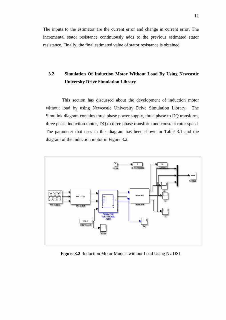
3.2 Simulation Of Induction Motor Without Load By Using Newcastle
University Drive Simulation Library
This section has discussed about the development of induction motor
without load by using Newcastle University Drive Simulation Library. The
Simulink diagram contains three phase power supply, three phase to DQ transform,
three phase induction motor, DQ to three phase transform and constant rotor speed.
The parameter that uses in this diagram has been shown in Table 3.1 and the
diagram of the induction motor in Figure 3.2.
Figure 3.2 Induction Motor Models without Load Using NUDSL
is3
is2
is1
Voltage Fed
3-ph Induction
Motor
t
To Workspace1
is1
To Workspace
Te
Scope1
Scope
157.1
Rotor Speed
DQ -> 3PH
DQ to 3PH
Clock
3PH -> DQ
3PH to DQ3PH Supply

12
Table 3.1 Parameter of Induction Motor without Load
Parameter Value
Stator resistance, Rs 1.2Ω
Rotor resistance, Rr 1.8Ω
Stator inductance, Ls 0.156H
Rotor inductance, Lr 0.156H
Magnetizing inductance, Lm 0.143H
Voltage 311.13V
Frequency 50Hz
Rated speed 1440rpm
Rated power 4000W
Numbers pole pairs 2
The input voltage that has been injected is 311.13 V three phase supply and
applied to three phase to DQ transform. The constant speed that has been injected is
157.1rad/s. The output of three phase to DQ transform and the rotor speed is by the
voltage fed three phase induction motor. The the output of induction motor is the
stator current. But to see the stator current clearly, it has been applied to DQ to three
phase transform . After that, the graph of torque and three phase stator current is
obtained by using a scope.
3.3 Simulation of Induction Motor with Load By Using Newcastle
University Drive Simulation Library.
This section has discussed the development of induction motor with load
by using Newcastle University Drive Simulation Library. The Simulink diagram
contains three phase power supply, three phase to DQ transform, three phase
induction motor, DQ to three phase transform, constant rotor speed and
mechanical dynamics. The parameter that uses in this diagram has been shown in
Table 3.2 and the diagram of the induction motor in Figure 3.3.

13
Figure 3.3 Induction Motor Models with Load Using NUDSL
Table 3.2 Parameter of Induction Motor with Load
Parameter Value
Stator resistance, Rs 1.2Ω
Rotor resistance, Rr 1.8Ω
Stator inductance, Ls 0.156H
Rotor inductance, Lr 0.156H
Magnetizing inductance, Lm 0.143H
Voltage 311.13V
Frequency 50Hz
Rated speed 1440rpm
Rated power 4000W
Numbers pole pairs 2
Inertia, J 0.024kgm2
rotor speed
is3
is2
is1
Voltage Fed
3-ph Induction
Motor
t
To Workspace1
is
To Workspace
Te
Scope1
Mechanical Dynamics
DQ -> 3PH
DQ to 3PH
Clock
3PH -> DQ
3PH to DQ3PH Supply

14
Firstly , the 311.13 V three phase voltage supply with the 50Hz are
injected into the three phase to DQ transform. The output of the three phase to
DQ transform and rotor speed enter into three phase induction motor. The outputs
of induction motor are stator current in DQ form and torque. The torque is
injected into the mechanical dynamic and its output is rotor speed. As mentioned
before, the output of induction motor which is stator current are applied into the
DQ to three phase transform and the output can be obtained by using a scope.
The difference between with load and without load is the with load have the
mechanical dynamic. Inside the subsystem of mechanical dynamics has one step
block and the step time adjusted to become 0.4, initial value is 0 and the final
value is equal to the TLoad.
3.4 Simulation of Induction Motor by Using Simulink MATLAB
This section will discuss on the Simulink diagram that are used to design the
estimated induction motor with a load. The Simulink diagram of induction
motor is designed by using d-axis and q-axis stator flux linkages, d-axis and q-
axis stator current in stator reference frame and amplitude of the stator current.
The d-axis stator flux linkages in Figure 3.7 use equation:
( ) (
)
( ) (5)
The q axis stator flux linkages in Figure 3.8 use equation:
( ) (
)
( ) (6)
D axis stator current in a stator reference frame in Figure 3.9 use equation:
[ ,
( ) (
)
( )-
+
(7)
Q axis stator current in stator reference frame in Figure 3.10 use equation:
[ ,
( ) (
)
( )-
+
(8)
15
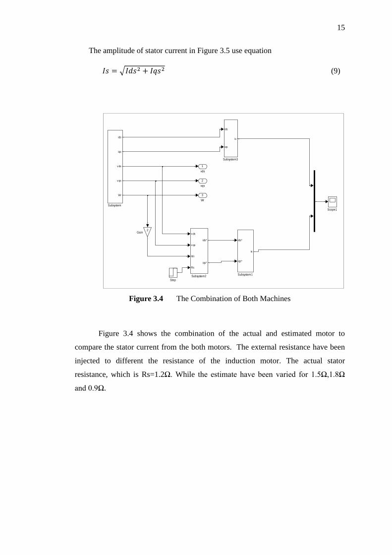
The amplitude of stator current in Figure 3.5 use equation
√ (9)
Figure 3.4 The Combination of Both Machines
Figure 3.4 shows the combination of the actual and estimated motor to
compare the stator current from the both motors. The external resistance have been
injected to different the resistance of the induction motor. The actual stator
resistance, which is Rs=1.2Ω. While the estimate have been varied for 1.5Ω,1.8Ω
and 0.9Ω.
3
Wr
2
vqs
1
vds
ids
iqs
is
Subsystem3
v ds
v qs
Wr
Rs
ids*
iqs*
Subsystem2
ids*
iqs*
is
Subsystem1
ids
iqs
v ds
v qs
Wr
Subsystem
Step
Scope1
2Gain
Recommended