Structure contours?• Topographic contours connect points of equal height above sea level
• Structure contours (also known as strike lines because they can run parallel to strike) connect points of equal elevation (height or depth) on a geological surface (eg. bedding)
• A plane with a consistent strike and dip has evenly spaced straight structure contours
• Steep dipping planes have closely spaced contours
• Shallow dipping planes have widely spaced contours
• Structure contours are used to:
• Map the subsurface and anything related to it (cross section, depth, horizon of interest)
2
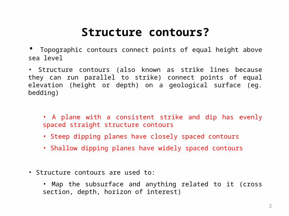
Topographic Contours• Topographic contours join all points of equal elevation
• Hills have closed contours
• Widely spaced contours - shallow slopes
• Closely spaced contours – steep slopes
3
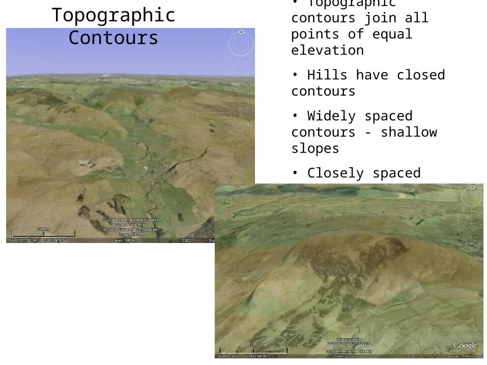
• Hills have closed contours
• Widely spaced contours - shallow slopes
• Closely spaced contours – steep slopes
• Streams and rivers follows vees in contours
Topographic maps
4
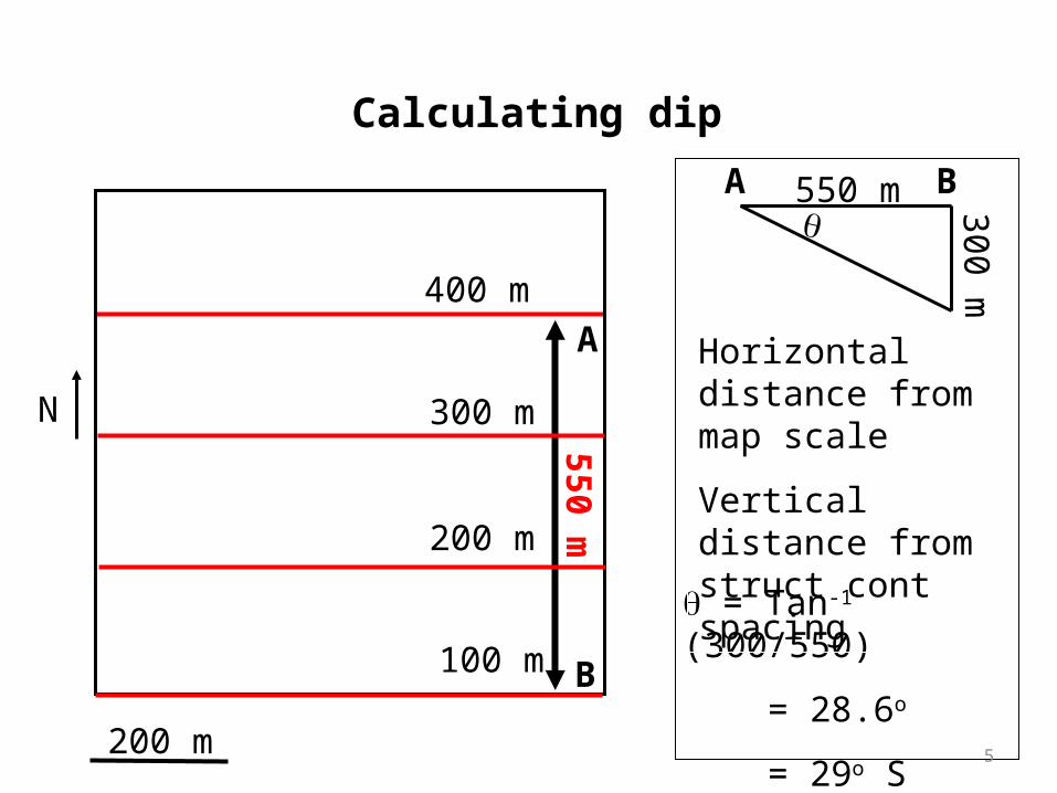
200 m
N
400 m
300 m
200 m
100 m
A
B
550 m 300 m
A B
= Tan-1 (300/550)
= 28.6o
= 29o S
Horizontal distance from map scale
Vertical distance from struct cont spacing
Calculating dip
550 m
5
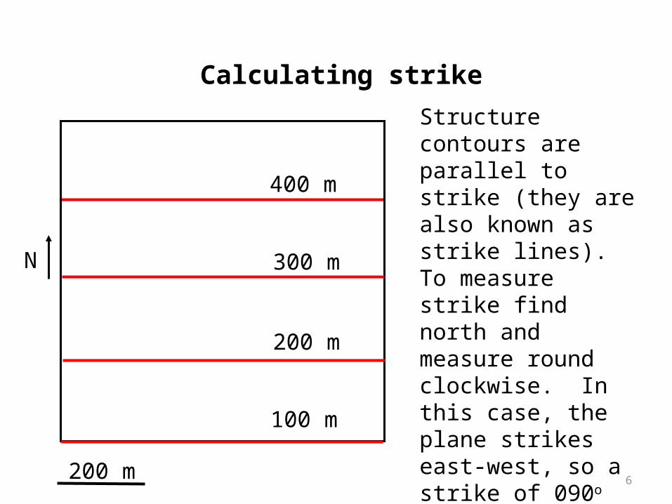
200 m
N
400 m
300 m
200 m
100 m
Calculating strike
Structure contours are parallel to strike (they are also known as strike lines). To measure strike find north and measure round clockwise. In this case, the plane strikes east-west, so a strike of 090o
Strike and dip of the plane is 090/29S
6
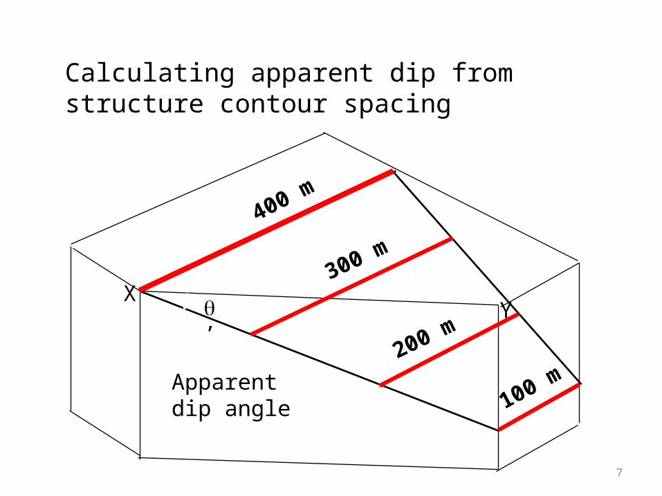
400 m
300 m
200 m
100 m
Calculating apparent dip from structure contour spacing
Apparent dip angle
’ YX
7
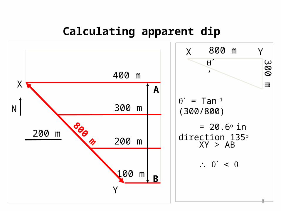
200 m
Y
X
N
400 m
300 m
200 m
100 m
X Y
300 m
= Tan-1 (300/800)
= 20.6o in direction 135o
’
Calculating apparent dip
A
B
XY > AB
800 m
800 m
8
T A
B
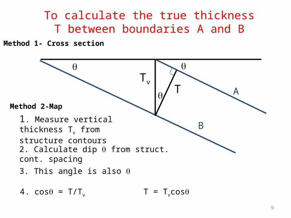
To calculate the true thickness T between boundaries A and B
Tv
1. Measure vertical thickness Tv from structure contours
2. Calculate dip from struct. cont. spacing
3. This angle is also
4. cos = T/Tv T = Tvcos
Method 1- Cross section
Method 2-Map
9
100
200
300400 500
600
700
400
500
600
700
500m
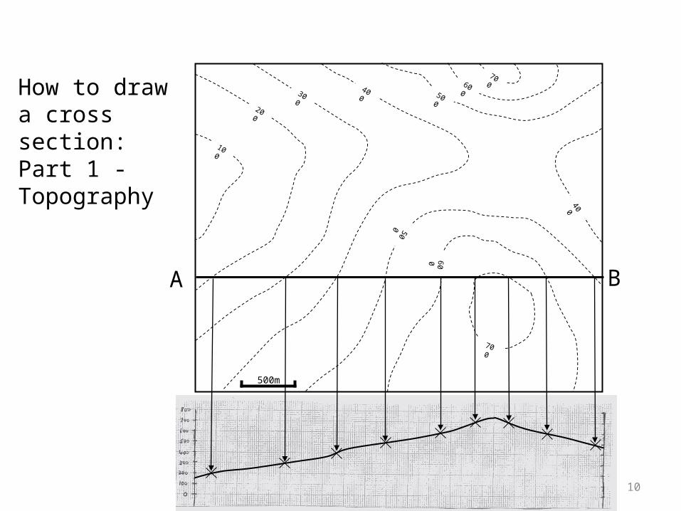
How to draw a cross section: Part 1 - Topography
A B
10
100
300 400 500
600
700
400
500
600
700
500m
200
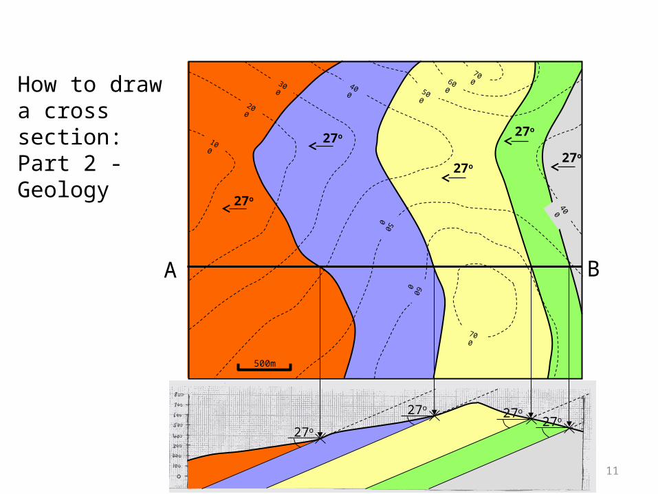
How to draw a cross section: Part 2 - Geology
A B
27o
27o
27o
27o
27o
27o
27o 27o
27o
11
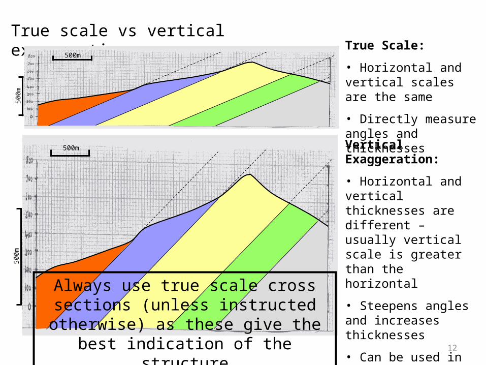
True scale vs vertical exaggeration500m
500m
True Scale:
• Horizontal and vertical scales are the same
• Directly measure angles and thicknesses
500m
500m
Vertical Exaggeration:
• Horizontal and vertical thicknesses are different – usually vertical scale is greater than the horizontal
• Steepens angles and increases thicknesses
• Can be used in areas of subdued topography or to make subtle structures clearer
Always use true scale cross sections (unless instructed otherwise) as these give the best
indication of the structure12
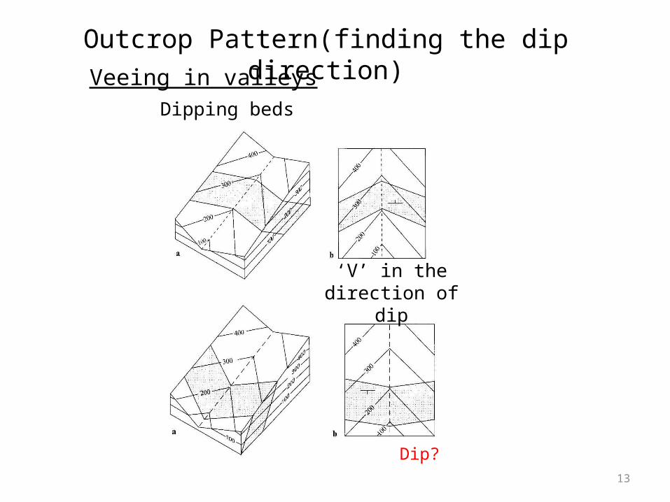
‘V’ in the direction of dip
Dipping beds
Veeing in valleys
Dip?
Outcrop Pattern(finding the dip direction)
13
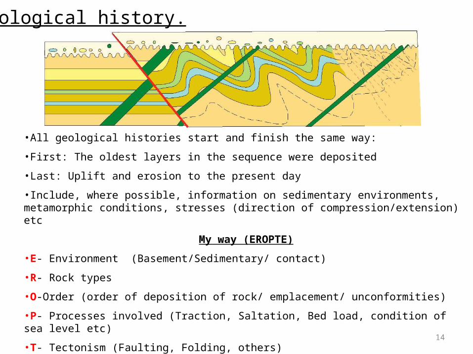
Geological history.
•All geological histories start and finish the same way:
•First: The oldest layers in the sequence were deposited
•Last: Uplift and erosion to the present day
•Include, where possible, information on sedimentary environments, metamorphic conditions, stresses (direction of compression/extension) etc
My way (EROPTE)
•E- Environment (Basement/Sedimentary/ contact)
•R- Rock types
•O-Order (order of deposition of rock/ emplacement/ unconformities)
•P- Processes involved (Traction, Saltation, Bed load, condition of sea level etc)
•T- Tectonism (Faulting, Folding, others)
•E- Erosion (Till now, erosion carved the area into the present topography) 14
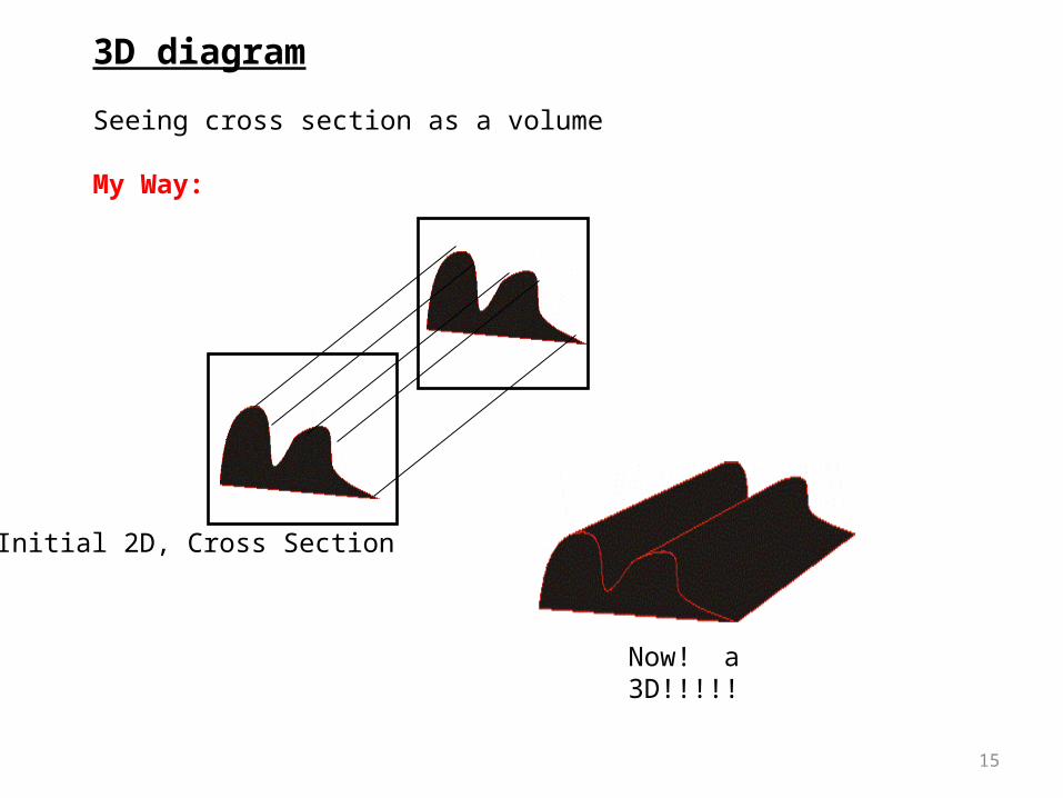
3D diagram
Seeing cross section as a volume
My Way:
Initial 2D, Cross Section
Now! a 3D!!!!!
15
Thanks to
•Structural Geology group (University of Leeds)
•Google earth
16
Recommended