ORIGINAL PAPER
Study of the effect of amino-functionalized multiwallcarbon nanotubes on dry sliding wear resistanceproperties of carbon fiber reinforced thermosetpolymers
G. Pincheira1 • C. Montalba1 • W. Gacitua3 • H.-M. Montrieux4 •
J. Lecomte-Beckers4 • M. F. Melendrez1 • P. Flores1,2
Received: 30 July 2015 / Revised: 26 November 2015 / Accepted: 5 January 2016
� Springer-Verlag Berlin Heidelberg 2016
Abstract This work investigates the effect of multiwall carbon nanotubes
(MWCNTs) on the mechanical and tribological behavior of a fiber reinforced
composite (FRC). Fiber reinforced composites and nano-engineered FRCs are
manufactured by resin transfer molding. In-plane tensile tests, in-plane shear tests
and through-thickness compression tests are used to assess the influence of
MWCNTs on the material mechanical behavior. Pin on disk dry sliding tests are
used to quantify the effect of MWCNTs on the friction coefficient and the specific
wear rate. It was determined that (1) MWCNTs have an influence on the
improvement on both the through-thickness compression strength and the specific
wear rate, and (2) they do not influence the material stiffness, in-plane tensile and
shear strengths and the friction coefficient. It is assumed that the observed
improvements are due to the demonstrated positive influence of the MWCNTs
effect on the matrix/reinforcement interfacial strength and on the matrix fracture
toughness.
Keywords Multiwall carbon nanotubes � Fiber reinforced composites �Mechanical testing � Wear resistance
& P. Flores
1 Department of Materials Engineering (DIMAT), Faculty of Engineering, University of
Concepcion, 270 Edmundo Larenas, Box 160-C, 4070409 Concepcion, Chile
2 Department of Mechanical Engineering (DIM), Faculty of Engineering, University of
Concepcion, 219 Edmundo Larenas, Box 160-C, 4070409 Concepcion, Chile
3 Department of Wood Engineering, University of Bıo-Bıo, Collao 1202, Box 5-C,
4081112 Concepcion, Chile
4 Special Metallic Materials, B52, University of Liege, 1 Chemin des Chevreuils, Sart Tilman,
4000 Liege, Belgium
123
Polym. Bull.
DOI 10.1007/s00289-016-1608-4

Introduction
The study of the tribological behavior of fiber reinforced composites (FRCs) based
on polymer matrix increases the possibilities for machine elements optimal design.
The constituents (type and content) of the FRCs play a relevant role on the material
mechanical behavior, wear rate and friction coefficient. Hence, a proper material
design must be focused on the required application. FRCs have been demonstrated
to be self-lubricant [1, 2] and corrosion resistant besides having the proper
mechanical performance (specific stiffness and strength, fracture toughness, fatigue
behavior) for structural applications. This multifunctional feature of FRCs is
interesting for machine element design, as shown in [3–6], during the designing of
bearings.
To improve the composite wear behavior, some research has been focused on the
study of the influence of fillers in the matrix on the material wear resistance. Larsen
et al. [7] reported that the addition of nano-CuO (1 vol.%) and micro-scale PTFE
(5 vol.%) particles (separately) on the reinforcement of epoxy carbon/aramid fibers
has a minor improvement in wear, but without producing differences in friction.
These authors concluded that the friction and wear properties are controlled by the
fibers. Su et al. [8] reported that the addition of nano-CaCO3 (5 wt.%), nano-SiO2
(5 wt.%) and nano-TiO2 (5 wt.%) contributed to increase the wear resistance a
carbon fabric/phenolic resin composite. This improvement is associated with the
observed changes on the transfer film. Suresha et al. [9] reduced wear in epoxy
carbon fiber reinforced by using a graphite filler (5 and 10 wt.%). The wear
reduction using graphite filler is associated with reduction in the removal of fiber, a
phenomenon that can be linked to the switch of the wear mechanism from
microcracking to microplowing/microcutting. The above examples were developed
under dry sliding conditions.
The improvement of the bonding at the matrix/reinforcement interface can
reduce the removal of fiber. Indeed, as established by Lee et al. [10], if the fracture
toughness of the matrix/reinforcement interface exceeds the minimum toughness of
either constituent and the fracture in the reinforcement is not favorable, the resulting
wear debris will be smaller in relation to the reinforcement size, thereby improving
the wear resistance.
Several authors, using different manufacturing techniques, have demonstrated
that the incorporation of multiwall carbon nanotubes (MWCNTs) on FRCs increases
the strength of the matrix/reinforcement interface. For example, in [11–13]
MWCNTs were grafted onto carbon fibers using the chemical vapor deposition
method, whereas [14] and [15] described the modification of the surface of sized
fibers by aqueous suspension deposition of MWCNTs. In addition, [15] and [16]
described the dispersion of MWCNTs into the resin (epoxy) to prepare a suspension.
For each of the reported techniques, significant improvements on the epoxy/fiber/
MWCNTs interfacial shear strength (IFSS) were obtained (from 11 % [12] to
175 % [11]), with the amount of improvement depending on the chosen technique,
the orientation and length of the MWCNTs, as well as the content (as established by
the model proposed by Yang et al. [17]) and the surface treatment of the MWCNTs,
Polym. Bull.
123

among other features. According to [18], the increase of the IFSS due to the addition
of MWCNTs can explain the increase of the interlaminar shear strength (ILSS). The
addition of MWCNTs to the resin or to the FRCs also increases the material fracture
toughness of the material, as demonstrated in [19] or [20] for epoxy resin and in
[21–24] for FRCs (glass fiber and carbon fiber reinforcement).
Besides, experimental evidence has established that the addition of MWCNTs in
epoxy resin enhances its wear resistance. Friederich and Schlarb [25] indicated the
relevance of the mixing method and the carbon nanotube treatment and its content
on the wear resistance of epoxy resin with MWCNTs, with 1.0 wt.% being the
optimal loading of MWCNTs to achieve the minimum specific wear rate. Cui et al.
[26] demonstrated that the addition of MWCNTs to epoxy is an efficient method to
improve the wear resistance and to lower the friction coefficient; they demonstrated
that a 0.5-wt.% amino-functionalized MWCNT composite achieves a reduction of
41.3 % on the wear rate compared to neat epoxy.
In this work, the influence of the addition of commercially amino-functionalized
MWCNTs on the in-plane and out-of-plane mechanical performance of epoxy was
assessed, as well as the friction coefficient and the wear resistance under dry sliding
conditions of the modified epoxy in epoxy twill weave carbon FRC manufactured
using resin transfer molding (RTM). The composite was designed with ca. 50 %
fiber volume fraction and the nFRC includes 0.3 wt.% of MWCNTs in the resin.
These values were set in agreement with the mechanical requirements (heavy-duty
machine elements conception) and the feasibility of achieving good MWCNTs
infiltration (see for example [27] and [28]) according to the selected manufacturing
procedure. The manufactured configurations were tested according to the ASTM D
3039 and ASTM D 4255 for the in-plane mechanical properties and according to
ASTM G 99 for the friction coefficient. Also, specific wear rate and through-
thickness compression test were performed according to [29]. The effects of the
MWCNTs on the composite were determined from the tests results.
Experimental description
Selected materials
The matrix is composed of the L20 epoxy resin with an EPH 161 hardener, which is
produced by Momentive, USA and purchased from R&G composites, Germany.
According to the technical data from the manufacturer, this resin system is designed
for heat resistant components up to 120 �C and groutings to approximately 10 mm
thick. In addition, curing occurs virtually free of shrinkage. The resin viscosity in
solution with the hardener at 25 �C is 700 cP and at 35 �C is 295 cP (the
measurements were made using a Fungilab Alpha series rotational viscometer). The
reinforcement is a twill 2/2 woven fabric of 204 g/m2 constructed by 200 tex
Carbon 3K yarns (the same in the warp and weft directions). The carbon fibers are
Tenax�—E HTA40 3K, and their manufacturer specifications are as follows: tensile
modulus of 238 GPa, tensile strength of 3950 MPa, density of 1.76 g/cm3 and ca.
1.3 % sizing based on epoxy resin. The fabrics are manufactured by Engineered
Polym. Bull.
123
Cramer Composites, Germany. Nanocyl (Belgium) provided the NC 3152 NH2
surface-modified MWCNTs. The MWCNTs are produced via the catalytic carbon
vapor deposition process.
Manufacturing process
The materials studied were manufactured using RTM. In this procedure, the resin is
injected into the mold at 4 bar and the composite is cured at room temperature for
24 h and post-cured for 15 h at 100 �C. The differences between the FRC and the
nano-engineered FRC (nFRC) were due to the resin preparation and the injection
temperature. For the FRC, the mixing ratio is 100:25 parts by weight of resin to
hardener mixed using mechanical stirring at room temperature. In the preparation of
the nFRC, 0.3-wt.% MWCNTs are poured into the resin and mixed in a propeller
stirrer (Velp, model Stirrer Type BS) for 10 min at 520 rpm. The mixture is then
placed in an ultrasonic bath (Elma, model Elmasonic P) at 30 �C for 90 min at
80 kHz. Because the addition of MWCNTs contributes to increase the resin
viscosity up to 840 cP, the mixture is then heated to 35 �C to obtain a viscosity
below 380 cP, followed by adding the hardener (at a 100:25 weight ratio) and
stirring the solution. The infusion is performed at 35 �C, and the mold is pre-heated
at the same temperature. A visual inspection of the doped epoxy on the inlet and
outlet hoses of the system is used to verify that MWCNTs filtration or precipitation
did not occur.
Two composites geometries were manufactured by means of the procedure above
described. The first one is a 12 plies laminate of 544 mm 9 250 mm 9 2.8 mm
used to characterize the in-plane mechanical behavior. The second one is a 45 plies
laminate of 250 mm 9 150 mm 9 10 mm used to obtained the specimens for the
through-thickness compression and tribological tests.
Laminates features
The laminate thickness is measured in at least ten points per manufactured laminate
using a Vernier caliper. The density is measured by immersion method according to
ASTM D 792 standard (five samples per material). The fiber volume fraction is
computed according to the ASTM D 3171 (method II). The hardness is measured
with a Barcol (Impressor GYZJ-934-1) as indicated the ASTM D 2583 and the
micro-Vickers hardness (using 500 g load during 10 s) is additionally measured for
the 45 plies laminates. All of this information is presented in Table 1, where the
same physical properties of the materials is achieved (Fiber volume fraction and
Density are similar).
Mechanical tests
The mechanical performance of the materials is determined from in-plane tensile
tests, in-plane shear tests and through-thickness compression tests. All the tests were
performed under quasi-static conditions in an Instron 8801 testing machine provided
with a 100 kN load cell. The specimens were cut by diamond wheel cutter. The
Polym. Bull.
123

mechanical parameters are presented in Table 2, where each value was obtained
from the average of five tests. In this table, the average value (AV) is complemented
with the standard deviation (SD), the relative standard variation (R. SD) and the
95 % interval of confidence (IC).
Tensile tests
The tensile tests were performed according to the ASTM D 3039 with a crosshead
speed of 1 mm/min. The specimens were obtained from the 12 plies laminates. The
specimens were clamped using hydraulic wedge grips. The stress was computed
from the load cell data and the initial specimen cross section. The longitudinal strain
was measured using a strain gage (length: 9.5 mm, width: 3.5 mm, gage length:
5 mm, gage factor 2.1, gage resistance: 120 X). The elastic modulus was computed
using a linear regression on the linear (elastic) range of the stress–strain curve and
the tensile strength was set at the maximal stress level.
In-plane shear tests
The in-plane shear tests were performed according to the ASTM D 4255 at a
crosshead speed of 0.3 mm/min. A two-rail testing device was embedded into the
testing machine. The specimens were obtained from the 12 plies laminates. The
Table 1 Laminates features
Number
of plies
Material Parameter Average
value
Standard
deviation (SD)
Relative
SD %
12 FRC Thickness (mm) 2.81 0.08 2.8
Density (g/cm3) 1.46 0.01 0.7
Fiber volume fraction 0.49 0.02 4.1
Barcol hardness 65.1 4.7 7.2
nFRC Thickness (mm) 2.77 0.09 3.2
Density (g/cm3) 1.45 0.01 0.7
Fiber volume fraction 0.51 0.02 3.9
Barcol hardness 66.7 4.4 6.6
45 FRC Thickness (mm) 10.18 0.04 0.4
Density (g/cm3) 1.43 0.01 0.7
Fiber volume fraction 0.52 0.01 1.9
Barcol hardness 61.7 3.6 5.8
Micro-Vickers hardness 38 14 37
nFRC Thickness (mm) 10.19 0.07 0.7
Density (g/cm3) 1.44 0.01 0.7
Fiber volume fraction 0.52 0.01 1.9
Barcol hardness 61.2 6.0 9.8
Micro-Vickers hardness 36 15 42
Quality control for both types of plates studied
Polym. Bull.
123

stress was computed from the load cell data and the initial specimen cross
section. The shear strain was measured using a strain gage (length: 9.5 mm, width:
3.5 mm, gage length: 5 mm, gage factor 2.1, gage resistance: 120 X) that was
placed as indicated in the norm. The in-plane shear modulus was obtained using a
linear approach for a shear strain range of 0–0.002 (due to the non-linear elastic–
plastic behavior of the material under the imposed condition) and the shear strength
was set at the achievement of a shear strain of 0.05, according to the norm.
Out-of-plane compression tests
The out-of-plane compression tests were performed according to [29] at a crosshead
speed of 0.5 mm/min. The specimens were 10 mm 9 10 mm 9 10 mm cubes
obtained from the 45 plies laminates. The specimens were compressed between two
lubricated steel plates. The stress was computed from the load cell data and the initial
specimen cross section. The longitudinal strain was measured using a strain gage
(length: 6 mm, width: 2.5 mm, gage length: 2 mm, gage factor 2.0, gage resistance:
120 X). The through-thickness compressive elastic modulus was computed using a
linear regression on the linear (elastic) range of the stress–strain curve and the
through-thickness compression strength was set at the maximal stress level.
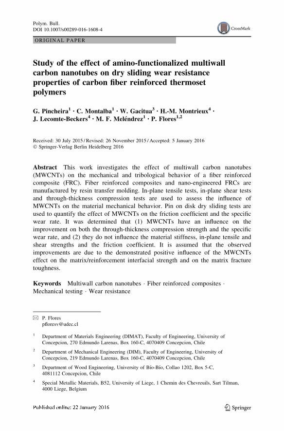
Tribological testing
The tribological tests were performed on a pin on disk apparatus (High Temperature
Tribometer from CSM Instruments) under dry sliding conditions (Fig. 1). The
Table 2 Mechanical properties of material composites prepared
Test Parameter Material AV SD R. SD % Limits of
IC (95 %)
Tensile Elastic modulus (GPa) (TM) FRC 54.1 1.4 2.6 ±2.6
nFRC 55.9 1.7 3.0 ±3.1
Tensile strength (MPa) (TS) FRC 692 81 11.7 ±149
nFRC 692 47 6.8 ±86
Poisson ratio, m (PC) FRC 0.058 0.008 13.8 ±0.015
nFRC 0.058 0.014 24.1 ±0.026
Ultimate strain (US) FRC 0.012 0.001 8.3 ±0.002
nFRC 0.011 0.001 9.1 ±0.002
In-plane shear Shear modulus (GPa) (SM) FRC 3.3 0.6 18.2 ±1.1
nFRC 3.5 1.1 31.4 ±2.0
Shear strength (MPa) (SS) FRC 49 3.4 6.9 ±6.2
nFRC 49 5.3 10.8 ±9.7
Through-thickness
compression
Elastic modulus (GPa)
(TTCM)
FRC 8.7 0.8 9.2 ±1.5
nFRC 9.3 1.2 12.9 ±2.2
Compressive strength MPa
(TTCS)
FRC 637 20 3.1 ±37
nFRC 690 26 3.7 ±48
Polym. Bull.
123
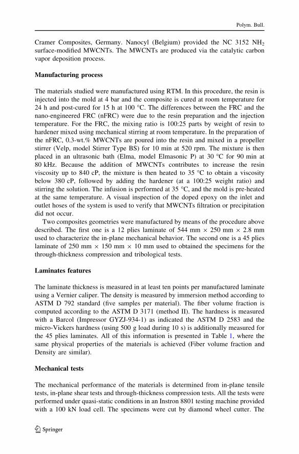
specimen is a 38 mm 9 38 mm 9 10 mm 45 plies composite, which is fixed on the
machine. The specimen is perpendicularly loaded by a stainless steel ball that slides
(without rotation) over the material surface following a circular path (as shown in
Fig. 2). The imposed load (F) is set to 2 N, the ball diameter is 10 mm and its speed
(v) is set to 0.98 m/s. The testing equipment records the frictional force during the
test to compute the friction coefficient. The initial pressure (p) imposed by the ball
over the specimen is approximately 107.5 MPa for the nFRC and 102.7 MPa for the
FRC, as computed by the Hertz contact theory using the data from Table 2, leading
to the pv testing condition of 105.4 and 100.6 MPa m/s for the nFRC and the FRC,
respectively.
Fig. 1 Pin on disk apparatus. Tribological properties are studied in it
Fig. 2 Wear specimen. Wearpath over the specimen isobserved after test
Polym. Bull.
123
The tests were performed at three sliding distances (L): 10,000, 30,000 and
50,000 m. Each test was repeated three times (new specimens were used in every
test). The mass of each of the specimens was measured before and after performing
the tests using a balance (precision of 0.01 mg). The mass loss (Dm) was used in the
Eq. 1 to determine the specific wear rate (q denotes the density of the specimen
established on Table 1).
Wr ¼ DmqFL
mm3=N m� �
: ð1Þ
Results and discussion
Mechanical Properties
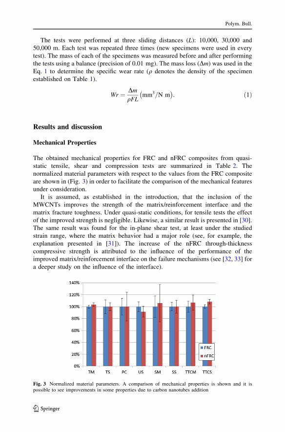
The obtained mechanical properties for FRC and nFRC composites from quasi-
static tensile, shear and compression tests are summarized in Table 2. The
normalized material parameters with respect to the values from the FRC composite
are shown in (Fig. 3) in order to facilitate the comparison of the mechanical features
under consideration.
It is assumed, as established in the introduction, that the inclusion of the
MWCNTs improves the strength of the matrix/reinforcement interface and the
matrix fracture toughness. Under quasi-static conditions, for tensile tests the effect
of the improved strength is negligible. Likewise, a similar result is presented in [30].
The same result was found for the in-plane shear test, at least under the studied
strain range, where the matrix behavior had a major role (see, for example, the
explanation presented in [31]). The increase of the nFRC through-thickness
compressive strength is attributed to the influence of the performance of the
improved matrix/reinforcement interface on the failure mechanisms (see [32, 33] for
a deeper study on the influence of the interface).
Fig. 3 Normalized material parameters. A comparison of mechanical properties is shown and it ispossible to see improvements in some properties due to carbon nanotubes addition
Polym. Bull.
123
Tribological tests
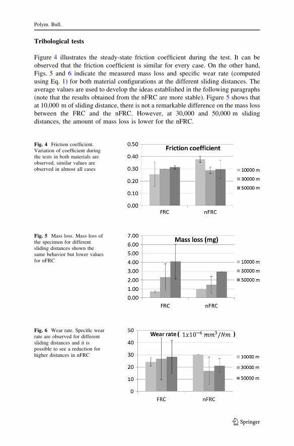
Figure 4 illustrates the steady-state friction coefficient during the test. It can be
observed that the friction coefficient is similar for every case. On the other hand,
Figs. 5 and 6 indicate the measured mass loss and specific wear rate (computed
using Eq. 1) for both material configurations at the different sliding distances. The
average values are used to develop the ideas established in the following paragraphs
(note that the results obtained from the nFRC are more stable). Figure 5 shows that
at 10,000 m of sliding distance, there is not a remarkable difference on the mass loss
between the FRC and the nFRC. However, at 30,000 and 50,000 m sliding
distances, the amount of mass loss is lower for the nFRC.
Fig. 4 Friction coefficient.Variation of coefficient duringthe tests in both materials areobserved, similar values areobserved in almost all cases
Fig. 5 Mass loss. Mass loss ofthe specimen for differentsliding distances shown thesame behavior but lower valuesfor nFRC
Fig. 6 Wear rate. Specific wearrate are observed for differentsliding distances and it ispossible to see a reduction forhigher distances in nFRC
Polym. Bull.
123

Figure 6 shows that the specific wear rate for the FRC is similar at the tested
sliding distances. Note that the specific wear rates for the nFRC experiences a
reduction of the specific wear rate at the higher sliding distances. The results
obtained from the tribological tests indicate that FRC and nFRC do not change the
value of the steady-state friction coefficient considerably. This result, together with
the fact that the behavior of both material configurations at a sliding distance of
10,000 m is similar in mass loss and specific wear rate (due to the high influence of
the surface resin layer), is used to deduce that the role of the transfer film at this
stage is not altered by the amount of MWCNTs contained in the nFRC debris. In
this case, the improvement on the wear resistance reported in [26] for epoxy resin
with a similar amount of amino-functionalized MWCNTs, but for different loading
conditions, were not reproduced. Nevertheless, reducing specific wear rate for nFRC
at higher sliding distances is associated with the CNTs influence on matrix/fiber
interface, helping to reduce interfacial debonding and keep the broken fiber in the
composite surface due to mechanical interlocking of CNTs with matrix, chemical
bonding between CNTs and bulk materials and local stiffening of polymer matrix
near fiber/matrix.
Microscopic analysis
The worn surfaces of the specimen at the different sliding distances were observed
using a scanning electron microscope (SEM, JSM-6380 JEOL). The worn surfaces
of the specimens were cleaned and then coated with a thin gold layer. Figures 7
and 8 show selected micrographs of the surfaces of FRC and nFRC, respectively.
The selection was based on the representativeness of the wear mechanisms. In
both figures, the images (a) and (b) represent the specimens state at a sliding
distance of 10,000 m, (c) and (d) at 30,000 m and (e) and (f) at 50,000 m. In the
figures, the blue arrow represents the sliding direction. Figure 7a shows the effects
when the pin passes over a poorly impregnated area, where it is possible to
identify: (1) the boundary between the original surface and the first ply of visible
fiber; (2) a transversally broken fiber; (3) the debris trapped between fibers; (4) an
obliquely broken fiber; (5) the beginning of fiber-matrix debonding. Figure 7b
shows the behavior of the material in a well-impregnated zone, where it is
possible to observe micro-plowing marks in the sliding direction and: (1) fractured
fiber; (2) fiber pullout and the subsequent disorientation of the removed material;
(3) the beginning of fiber-matrix debonding.
In Fig. 7c, d, micro-cracking was the most commonly observed phenomenon.
Figure 7c shows: (1) and (4) a micro-crack that divides the matrix; (2) and (3)
broken fibers; (4) several micro-cracks in the original surface. Figure 7d shows: (1)
fiber pullout; (2) broken fibers disoriented in the sliding direction; (3) and (4) micro-
cracking and the resin debonding zone. Figure 7e shows: (1) and (2) several broken
fibers; (3) the boundary between the worn surface and the resin surface parallel to
the sliding direction. Figure 7f presents: (1) and (2) plowing marks on the matrix
due to plastic deformation in the resin, which, according to [7], occurs through the
application of cyclic loads on the specimens and the generation of high temperatures
Polym. Bull.
123
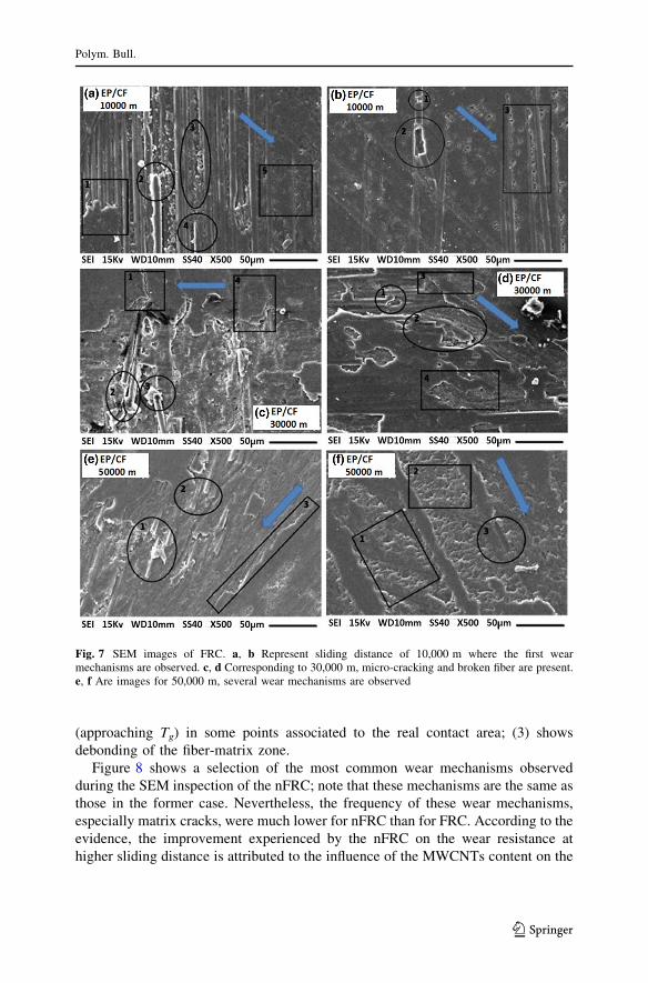
(approaching Tg) in some points associated to the real contact area; (3) shows
debonding of the fiber-matrix zone.
Figure 8 shows a selection of the most common wear mechanisms observed
during the SEM inspection of the nFRC; note that these mechanisms are the same as
those in the former case. Nevertheless, the frequency of these wear mechanisms,
especially matrix cracks, were much lower for nFRC than for FRC. According to the
evidence, the improvement experienced by the nFRC on the wear resistance at
higher sliding distance is attributed to the influence of the MWCNTs content on the
Fig. 7 SEM images of FRC. a, b Represent sliding distance of 10,000 m where the first wearmechanisms are observed. c, d Corresponding to 30,000 m, micro-cracking and broken fiber are present.e, f Are images for 50,000 m, several wear mechanisms are observed
Polym. Bull.
123
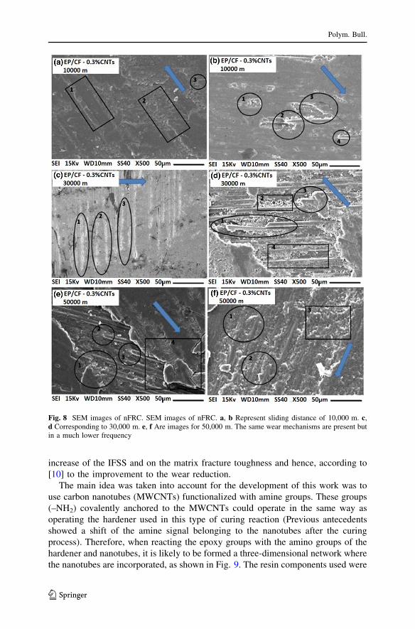
increase of the IFSS and on the matrix fracture toughness and hence, according to
[10] to the improvement to the wear reduction.
The main idea was taken into account for the development of this work was to
use carbon nanotubes (MWCNTs) functionalized with amine groups. These groups
(–NH2) covalently anchored to the MWCNTs could operate in the same way as
operating the hardener used in this type of curing reaction (Previous antecedents
showed a shift of the amine signal belonging to the nanotubes after the curing
process). Therefore, when reacting the epoxy groups with the amino groups of the
hardener and nanotubes, it is likely to be formed a three-dimensional network where
the nanotubes are incorporated, as shown in Fig. 9. The resin components used were
Fig. 8 SEM images of nFRC. SEM images of nFRC. a, b Represent sliding distance of 10,000 m. c,d Corresponding to 30,000 m. e, f Are images for 50,000 m. The same wear mechanisms are present butin a much lower frequency
Polym. Bull.
123

bisPhenol-A-Epichlorhydrin (70 %), Bisphenol-F-Epichlorhydrin (20 %) and an
epoxidized molecule that gives flexibility to the thermoset polymer as 1.6-Bis(2.3-
Epoxypropoxy)hexane (10 %). On the other hand, the hardener is composed of
diethylenetriamine (50 %), Bisphenol A (49 %) present as a solvent and
m-phenylenebis(methylamine) (1 %). Basically, all the curing reaction focuses on
bisphenol A and F (Epichlorhydrin) and diethylenetriamine, coupled with the amine
groups of the MWCNTs.
Depending on the chemical structure of curing agent used and conditions of cure,
it is possible to obtain thermosetting polymers with mechanical properties ranging
from extreme flexibility to full hardness and rigidity, high adhesive strength, good
tensile properties and high temperature insulation. Therefore, a possible increase in
the degree of crosslinking because the (NH2)-MWCNTs, would mean an
improvement in the mechanical properties of the composites. However, this was
not found in the above results (this may be because the fiber can decrease the degree
of crosslinking of the resin). In Table 2, a significant improvement in the
compounds are not evidenced; this can be seen by comparing the obtained material
with and without (NH2)-MWCNTs. But, although the friction coefficient does not
change, the specific wear rate if tends to reduce. The above occurs because
functionalizing nanotubes create defects in both walls at its ends, in many cases the
tubes are broken into smaller pieces resulting in a drastic loss in mechanical and
electrical properties. The improvement in the rate of wear is due to the nanotubes
improve the matrix/reinforcement interface. But due to its functionalization it is not
sufficient to reduce the coefficient of friction of the material because their
mechanical properties decreased.
Fig. 9 Mechanism of the curing reaction using (NH2)-MWCNT and different types of crosslinkers. Athree-dimensional covalent network coupled with the nanotubes is obtained
Polym. Bull.
123

Conclusions
From the dry-sliding tribology tests (pin on disk) the inclusion of MWCNTs on the
composite were found to (a) not modify the friction coefficient and (b) tend to
reduce the specific wear rate. It can be remarked from the SEM images that the
nFRC exhibited a reduced amount of wear compared to the FRC, primarily in the
matrix cracking. This improvement of the wear resistance is attributed to the effect
of the MWCNTs on the enhancement of the strength of the matrix/reinforcement
interface and on the matrix fracture toughness and not to an improvement of the
resin transfers film effect.
The inclusion of the MWCNTs in the epoxy carbon FRCs manufactured by RTM
improves the through-thickness compressive stiffness and strength. Moreover, the
other mechanical properties under study are not affected by incorporating
MWCNTs.
Acknowledgments The financial support by CONICYT through the projects Fondef (D08i1138 and
IT13i10054) and CONICYT Regional (CIPA/R08C1002). The authors would like to thank the National
Commission for Scientific and Technological Research, CONICYT (Ministry of Education Government
of Chile) by PhD scholarship Grant No. 21100601 of G. Pincheira. The content is solely the responsibility
of the authors and does not necessarily represent the official views of the CONICYT.
References
1. Wu J, Cheng XH (2009) The tribological properties of Kevlar pulp reinforced epoxy composites
under dry sliding and water lubricated condition. Wear 26:1293–1297
2. Suresha B, Kunigal Shiva Kumar, Seetharamu S, Sampath Kumaran P (2010) Friction and dry sliding
wear behavior of carbon and glass fabric reinforced vinyl ester composites. Tribol Int 43:602–609
3. Kim BC, Lee DG (2009) Development of a spherical bearing with uni-directional carbon/epoxy
composite. Compos Struct 89:102–109
4. Park DC, Lee SM, Kim BC, Kim HS, Lee DG (2006) Development of heavy-duty hybrid carbon-
phenolic hemispherical bearings. Compos Struct 73:88–98
5. Yu HN, Kim SS, Lee DG (2009) Optimum design of aramid-phenolic/glass-phenolic composite
journal bearings. Compos Part A 40:1186–1191
6. Kim SS, You HN, Hwang IU, Lee DG (2009) Development of the carbon/phenolic composite
shoulder bearing. Compos Struct 88:26–32
7. Larsen TO, Andersen TL, Thorning B, Vigild ME (2006) The effect of particle addition and fibrous
reinforcement on epoxy-matrix composites for severe sliding conditions. Wear 264:857–868
8. Su F, Zhang Z, Liu W (2006) Mechanical and tribological properties of carbon fabric composites
filled with several nano-particles. Wear 260:861–868
9. Suresha B, Kishore S, Seetharamu S, Kumaran PS (2009) Investigations on the influence of graphite
filler on dry sliding wear and abrasive wear behaviour of carbon fabric reinforced epoxy composites.
Wear 267:1405–1414
10. Lee GY, Dharan CKH, Ritchie RO (2002) A physically-based abrasive wear model for composite
materials. Wear 252:322–331
11. Lv P, Feng Y, Zhang P, Chen H, Zhao N, Feng (2011) W. Increasing the interfacial strength in carbon
fiber/epoxy composites by controlling the orientation and length of carbon nanotubes grown on the
fibers. Carbon 49:4665–4673
12. Sager RJ, Klein PJ, Lagoudas DC, Zhang Q, Liu J, Dai L, Baur JW (2009) Effect of carbon nanotubes
on the interfacial shear strength of T650 carbon fiber in an epoxy matrix. Compos Sci Technol
69:898–904
13. An F, Lu C, Li Y, Guo J, Lu X, Lu H, He S, Yang Y (2012) Preparation and characterization of
carbon nanotube-hybridized carbon fiber to reinforce epoxy composite. Mater Des 33:197–202
Polym. Bull.
123

14. Li M, Gu Y, Liu Y, Li Y, Zhang Z (2013) Interfacial improvement of carbon fiber/epoxy composites
using a simple process for depositing commercially functionalized carbon nanotubes on the fibers.
Carbon 52:109–221
15. Godara A, Gorbatikh L, Kalinka G, Warrier A, Rochez O, Mezzo L, Luizi F, van Vuure AW, Lomov
SV, Verpoest I (2010) Interfacial shear strength of a glass fiber/epoxy bonding in composites
modified with carbon nanotubes. Compos Sci Technol 70:1346–1352
16. Chandrasekaran VCS, Advani SG, Santare MH (2010) Role of processing on interlaminar shear
strength enhancement of epoxy/glass fiber/multi-walled carbon nanotube hybrid composites. Carbon
48:3692–3699
17. Yang L, He X, Mei L, Tong L, Wang R, Li Y (2012) Interfacial shear behavior of 3D composites
reinforced with CNT-grafted carbon fibers. Compos Part A 43:1410–1418
18. Chandrasekaran VCS, Advani SG, Santare MH (2011) Influence of resin properties on interlaminar
shear strength of glass/epoxy/MWNT hybrid composites. Compos Part A 42:1007–1016
19. Gojny F, Wichmann MHG, Fiedler B, Schulte K (2005) Influence of different carbon nanotubes on
the mechanical properties of epoxy matrix composites—a comparative study. Compos Sci Technol
65:2300–2313
20. Tang Y, Ye L, Zhang Z, Friederich K (2013) Interlaminar fracture toughness and CAI strength of
fibre-reinforced composites with nanoparticles—a review. Compos Sci Technol 86:26–37
21. Godara A, Mezzo L, Luizi F, Warrier A, Lomov SV, Van Vuure AW, Gorbatikh L, Moldenaers P,
Verpoest I (2009) Influence of carbon nanotube reinforcement on the processing and the mechanical
behavior of carbon fiber/epoxy composites. Carbon 47:2914–2923
22. Karapappas P, Vavouliotis A, Tsotra P, Kostopoulos V, Paipetis A (2009) Enhanced fracture
properties of carbon reinforced composites by the addition of multi-wall carbon nanotubes. J Compos
Mater 43:977–985
23. Lee SH, Kim H, Hang S, Cheong SK (2012) Interlaminar fracture toughness of composites laminates
with CNT-enhanced nonwoven carbon tissue interleave. Compos Sci Technol 73:1–8
24. Mujika F, Vargas G, Ibarretxe J, De Gracia J, Arrese A (2012) Influence of the modification with
MWCNT on the interlaminar fracture properties of long carbon fiber composites. Compos Part B
43:1336–1340
25. Jacobs O, Schabel B (2008) Wear behavior of carbon nanotube-reinforced polyethylene and epoxy
composites. In: Friederich K, Schlarb AK (eds) Tribology of polymeric nanocomposites. In: Briscoe
BJ (ed) Tribology and Interface Engineering Series, vol 55. Elsevier, UK, pp 209–242
26. Cui LJ, Geng HZ, Wang WY, Chen LT, Gao J (2013) Functionalization of multi-wall carbon
nanotubes to reduce the coefficient of friction and improve the wear resistance of multi-wall carbon
nanotube/epoxy composites. Carbon 54:277–282
27. Jimenez-Suarez A, Campo M, Sanchez M, Romon C, Urena A (2012) Influence of the functional-
ization of carbon nanotubes on calendaring dispersion effectiveness in a low viscosity resin for
VARIM processes. Compos Part B 43:3482–3490
28. Aguilar-Ventura I, Lubineau G (2013) The effect of bulk-resin CNT-enrichment on damage and
plasticity in shear-loaded laminated composites. Compos Sci Technol 84:23–30
29. Kim BC, Park DC, Kim BJ, Lee DG (2010) Through-thickness compressive strength of a carbon/
epoxy composite laminate. Compos Struct 92:480–497
30. De Greef N, Gorbatikh L, Godara A, Mezzo L, Lomov S, Verpoest I (2011) The effect of carbon
nanotubes on the damage development in carbon fiber/epoxy composites. Carbon 49:4650–4664
31. Fernandez C, Medina C, Pincheira G, Canales C, Flores P (2013) The effect of multiwall carbon
nanotubes on the in-plane shear behavior of epoxy fiber reinforced composites. Compos Part B
55:421–425
32. Gonzalez C, Llorca J (2007) Mechanical behavior of unidirectional fiber-reinforced polymers under
transverse compression: microscopic mechanisms and modeling. Compos Sci Technol 67:2795–2806
33. Medina C, Molina-Aldareguıa J, Gonzalez C, Melendrez M, Flores P, Llorca J (2015) Comparison of
push-in and push-out tests for measuring interfacial shear strength in nano-reinforced composite
materials. J Compos Mater. doi:10.1177/0021998315595115
Polym. Bull.
123
Recommended