Key to symbols
App’dCh’k’dDescriptionDrawnDateRev
RevStatus
Drawing Number
Scale at A2
Eng check
Approved
Coordination
Dwg check
Drawn
Designed
Title
Notes
Client
Reference drawings
Security
C:\documents and settings\pat30160\pwlocal\d0137997\322538-CCB-0022-01_0.dwg Jun 10, 2015 - 3:26PM pat30160
TFW
©
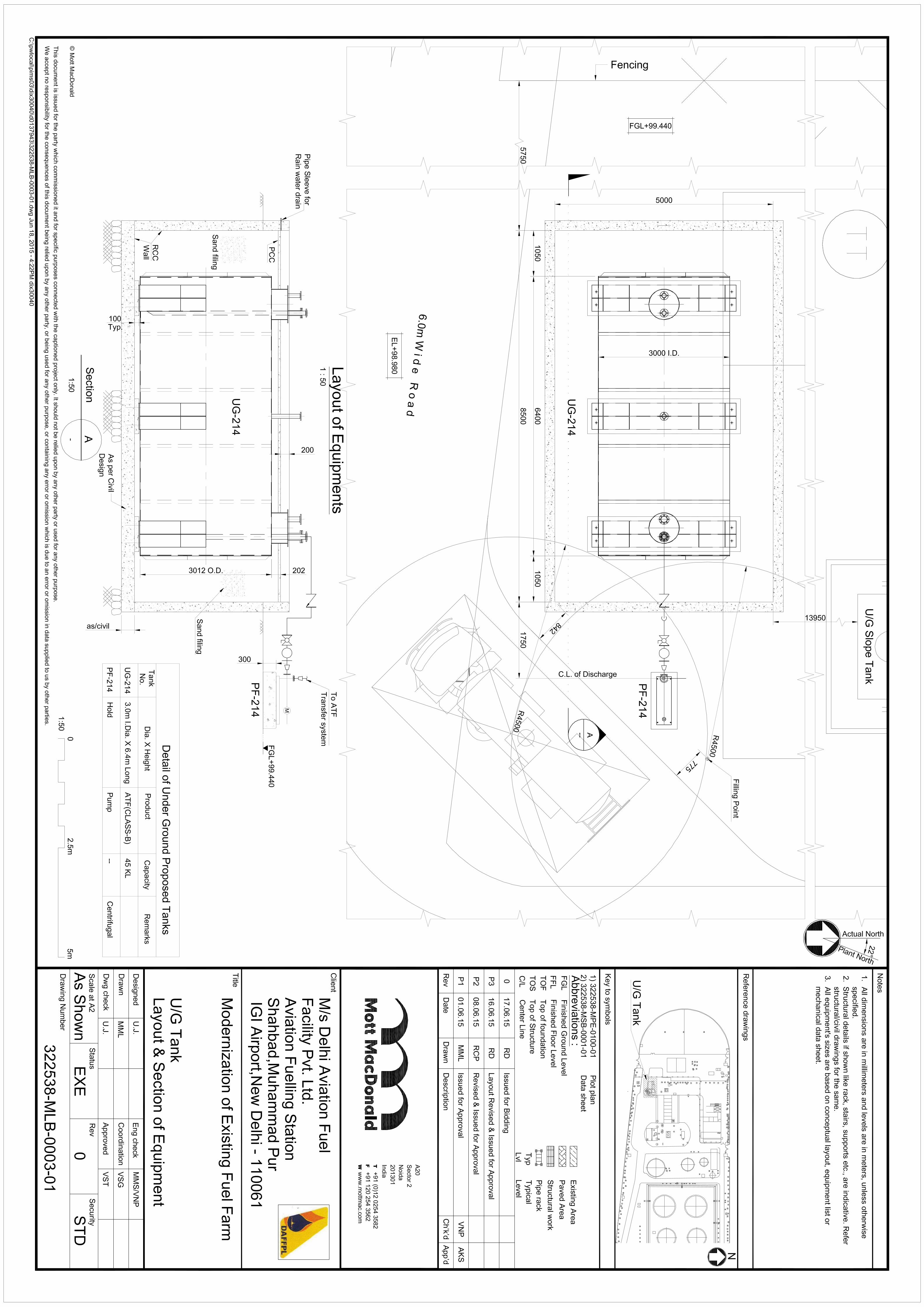
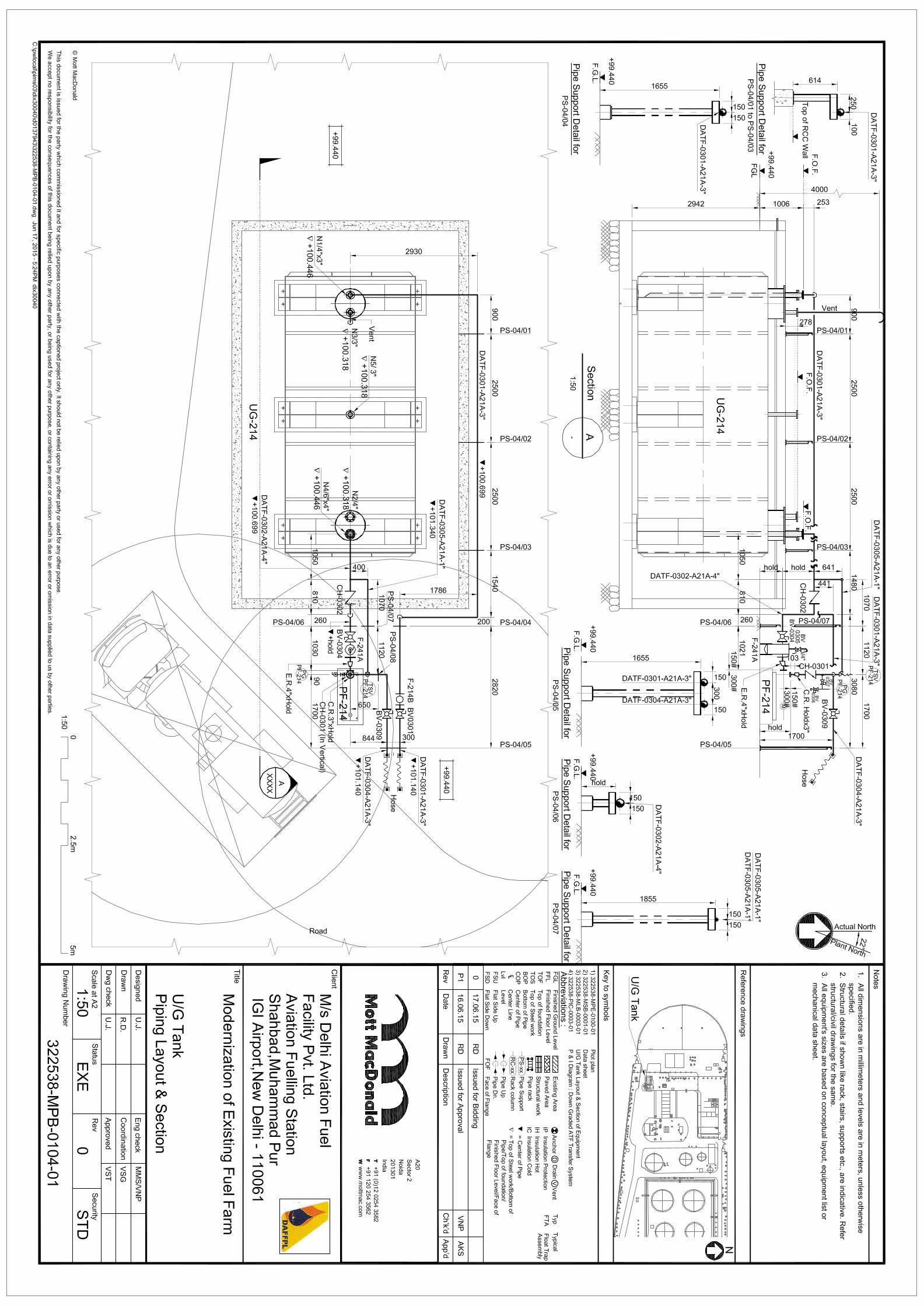
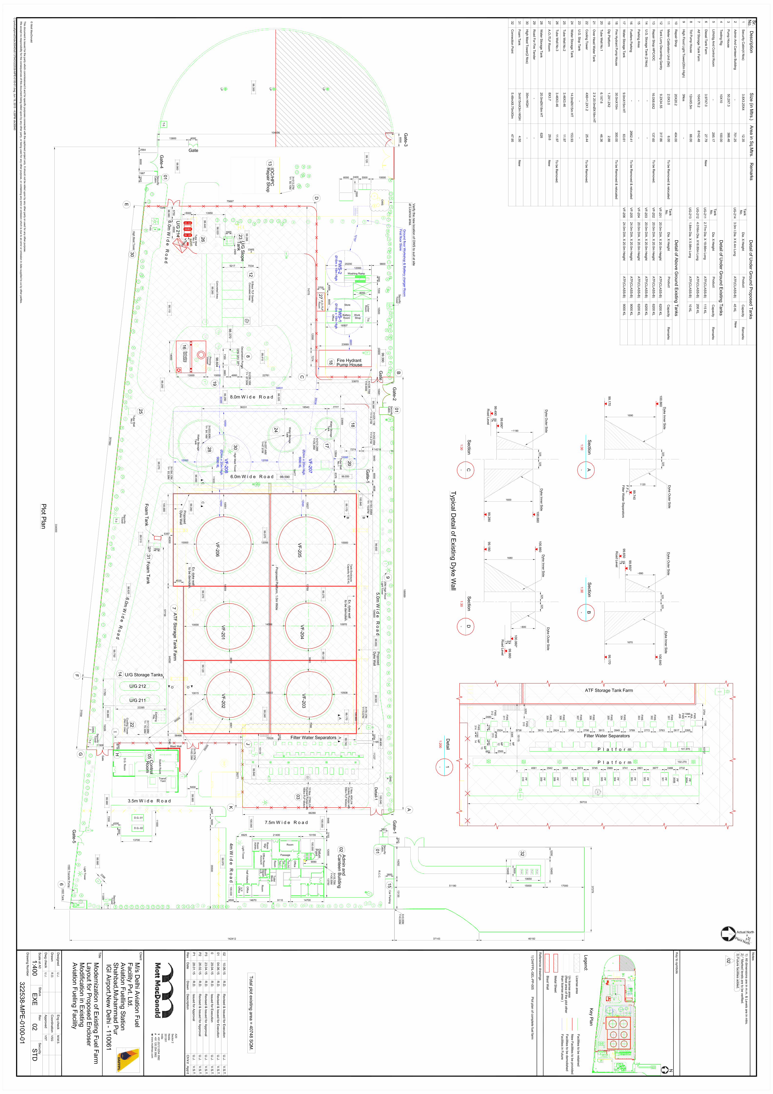
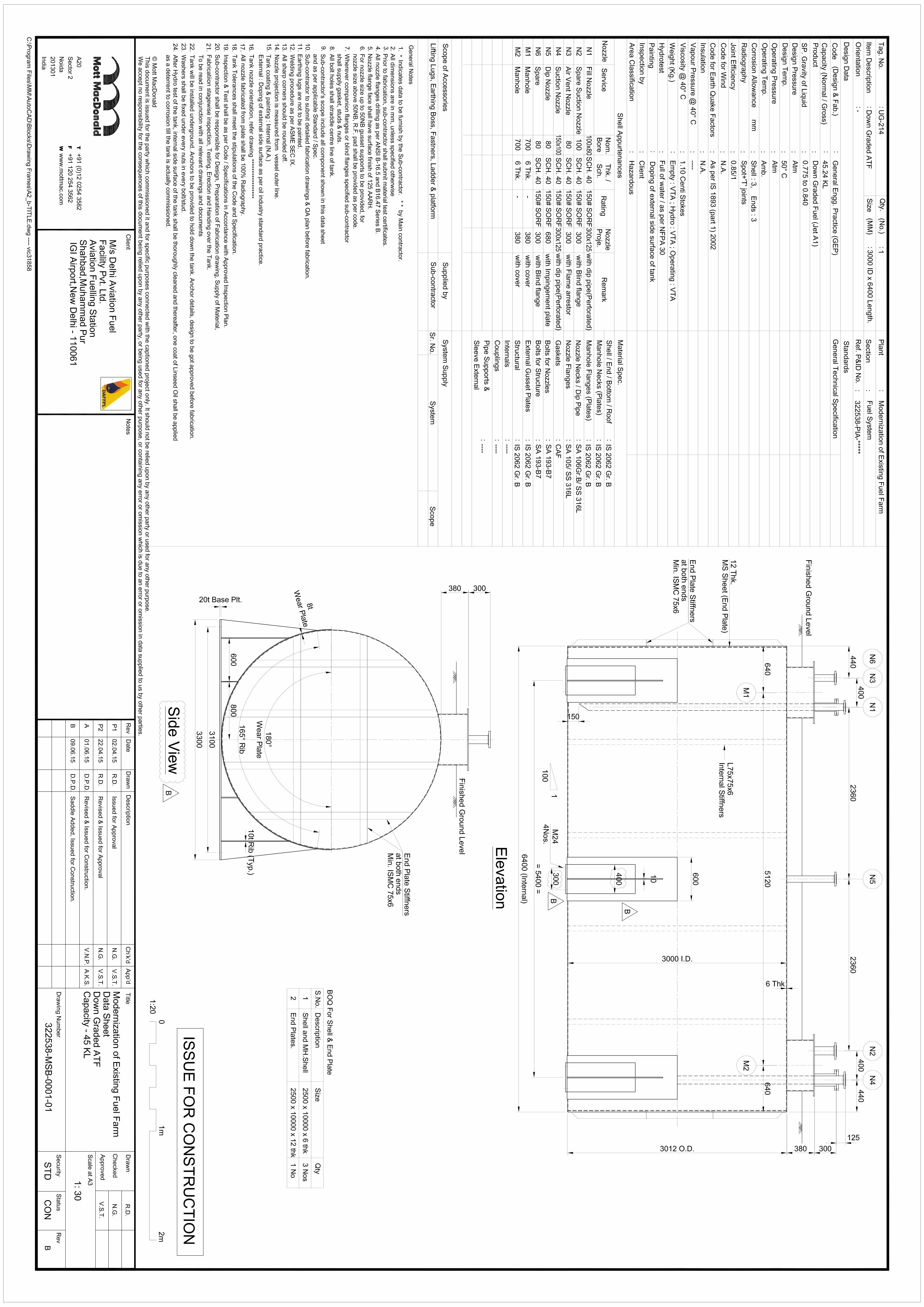
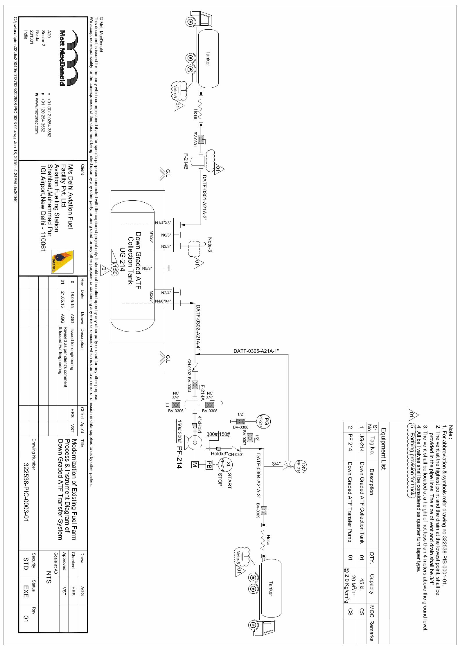
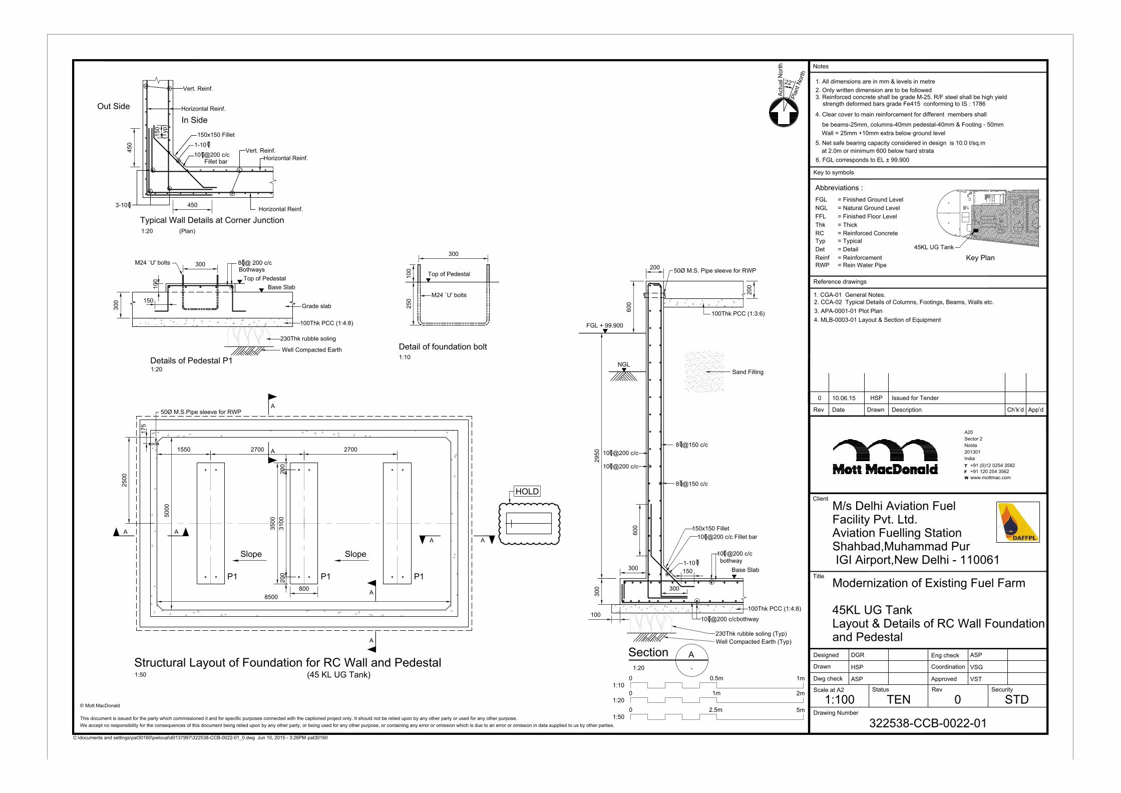
Modernization of Existing Fuel Farm
45KL UG Tank
Layout & Details of RC Wall Foundation
and Pedestal
M/s Delhi Aviation Fuel
Facility Pvt. Ltd.
Aviation Fuelling Station
Shahbad,Muhammad Pur
IGI Airport,New Delhi - 110061
DGR
HSP
ASP
ASP
VSG
VST
1:100 TEN
322538-CCB-0022-01
0 STD
A20
Sector 2
Noida
201301
India
+91 (0)12 0254 3582
+91 120 254 3562
www.mottmac.com
This document is issued for the party which commissioned it and for specific purposes connected with the captioned project only. It should not be relied upon by any other party or used for any other purpose.
We accept no responsibility for the consequences of this document being relied upon by any other party, or being used for any other purpose, or containing any error or omission which is due to an error or omission in data supplied to us by other parties.
Mott MacDonald
Structural Layout of Foundation for RC Wall and Pedestal
1:50
(45 KL UG Tank)
A
A
AA
A
A
A A
8500
P1 P1 P1
2700 2700
3500
200
3100
200
800
2500
SlopeSlope
17
5
50Ø M.S.Pipe sleeve for RWP
HOLD
1550
5000
8 @150 c/c 0
8 @150 c/c 0
300
300
2950
bothway
10 @200 c/c0
bothway
60
0
FGL + 99.900
Section
A
-1:20
230Thk rubble soling (Typ)
Well Compacted Earth (Typ)
100Thk PCC (1:4:8)
200
100
10
0
Details of Pedestal P1
Grade slab
100Thk PCC (1:4:8)
150x150 Fillet
10 @200 c/c Fillet bar0
150
1-10
0
30
0
600
8 @ 200 c/c0
Bothways
300
M24 `U' bolts
10
02
50
Detail of foundation bolt
1:10
1:20
Typical Wall Details at Corner Junction
In Side
450
Vert. Reinf.
450
15
0
(T
yp
)
Horizontal Reinf.
Horizontal Reinf.
Vert. Reinf.
Horizontal Reinf.
Out Side
1:20
Fillet bar
10 @200 c/c 0
1-10
0
10 @200 c/c0
10 @200 c/c 0
10 @200 c/c 0
150
300
M24 `U' bolts
(Plan)
300
100Thk PCC (1:3:6)
Sand Filling
50Ø M.S. Pipe sleeve for RWP
20
0
230Thk rubble soling
Well Compacted Earth
at 2.0m or minimum 600 below hard strata
5. Net safe bearing capacity considered in design is 10.0 t/sq.m
2. Only written dimension are to be followed
6. FGL corresponds to EL ± 99.900
1. All dimensions are in mm & levels in metre
3. Reinforced concrete shall be grade M-25. R/F steel shall be high yield
strength deformed bars grade Fe415 conforming to IS : 1786
4. Clear cover to main reinforcement for different members shall
be beams-25mm, columns-40mm pedestal-40mm & Footing - 50mm
P
la
n
t
N
o
r
t
h
Actu
al N
orth
Wall = 25mm +10mm extra below ground level
2
2
°
Thk
FGL
NGL
FFL
Abbreviations :
= Thick
Typ
Det
RC
= Typical
= Detail
= Finished Ground Level
= Natural Ground Level
= Finished Floor Level
= Reinforced Concrete
Reinf = ReinforcementKey Plan
RWP = Rein Water Pipe
1. CGA-01 General Notes.
2. CCA-02 Typical Details of Columns, Footings, Beams, Walls etc.
0 10.06.15 HSP Issued for Tender
4. MLB-0003-01 Layout & Section of Equipment
3. APA-0001-01 Plot Plan
1m 2m0
1:20
1:10
0 1m0.5m
3-100
45KL UG Tank
150x150 Fillet
NGL
Recommended