Surface Engineering for Aerospace Applications
Lecture 21
Jeffrey H. Sanders
NSF Summer Institute on Nano Mechanics and MaterialsSurface Engineering and Coatings
July 30, 2004
2
Outline
• Introduction– Surface Engineering– My Perspective
• Tribology Programs– Nanocomposite Hard Coatings– Anti-fretting Coatings– MEMS R&D
• Paint Related Programs– Specialty Materials– Paint processes
• Component Surface Treatments– Laser Shock Processing– Low Plasticity Burnishing
• Summary

3
Surface Engineering
SE defined as “treatment of the surface and near-surface regions of a material to allow the surface to perform functions that are distinct from those functions demanded from the bulk of the material”
Modified Surface(cleaning, finishing, coating)
Bulk Material(metals, semiconductors, ceramics, polymers)
Strength, modulus, fatigue, creep, conductivity, etc…
Corrosion, friction, wear, hardness, appearance, etc…
Ref: C.M. Cotell and J.A. Sprague in the ASM Handbook Vol 5, Preface

4
Air Force Research Laboratory
AFRL Mission
Leading the discovery, development, and integration of affordable warfighting technologies for our air and space force.
AFRL Vision
We defend America by unleashing the power of innovative science and technology.
AF Office of Scientific Research
Air Vehicles Directorate
Directed Energy Directorate
Human Effectiveness Directorate
Information Directorate
Materials and MfgDirectorate
Munitions Directorate
Propulsion Directorate
Sensors Directorate
Space Vehicles Directorate

5
Materials and Mfg Directorate
• Nonmetallic Materials Division
– Polymers
– Structural Materials
– Nonstructural Materials
• Metals, Ceramics and NDE Division
– Metals
– Ceramics
– Nondestructive Evaluation
• Mfg Technology Division
• Air Base and Environmental Technology Division
• Survivability and Sensor Materials Division
• Systems Support Division
• Integration and Operations Division
6
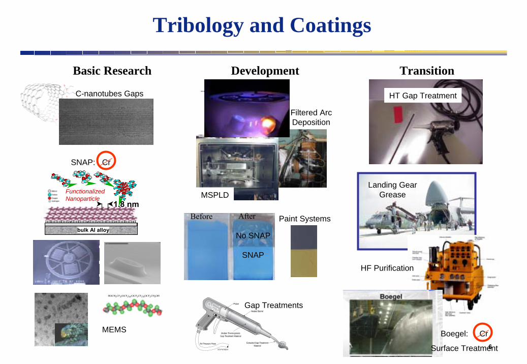
Tribology and Coatings
Basic Research Development Transition
HOCH2CF2(OCF2)m(OCF2CF2)nOCF2CH2OH
372-P-97520-9
Air Pressure Hose
Heated Barrel
Extruded Gap-TreatmentMaterial
Molten ThermoplasticGap-Treatment Material
Piston
C-nanotubes Gaps
Before After
No SNAP
SNAP
MSPLD
Filtered ArcDeposition
MEMS
Gap Treatments
Paint Systems
Boegel: Cr
Surface Treatment
HT Gap Treatment
Landing GearGrease
HF Purification
FunctionalizedNanoparticle
SNAP: Cr
bulk Al alloy
1.8 nm

7
• Develop Materials and Processes for Applications As:
– Solid Lubricants and Hard Coatings
– Spacecraft Thermal Control Coatings
– Spacecraft Lubrication Systems
– Specialty Coatings
– Aircraft Coatings and Corrosion Control• Provide Operational Systems Support For:
– Fluids and Lubricants Issues on Air and Space Systems
Tribology and Coatings
8
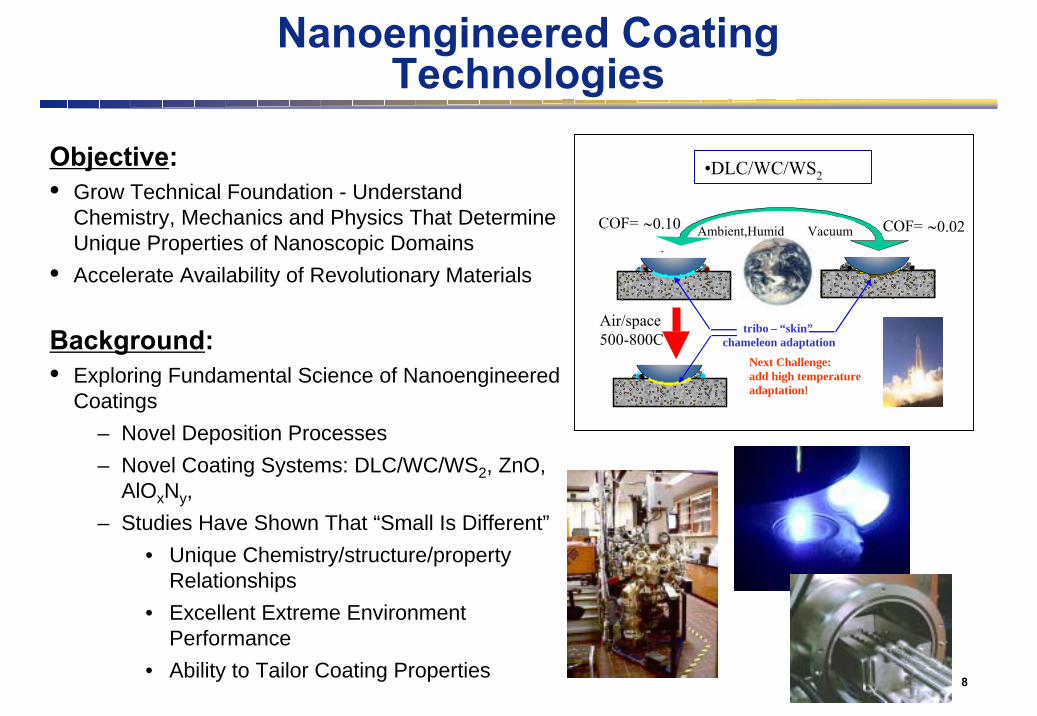
Nanoengineered Coating Technologies
Background:• Exploring Fundamental Science of Nanoengineered
Coatings – Novel Deposition Processes– Novel Coating Systems: DLC/WC/WS2, ZnO,
AlOxNy,– Studies Have Shown That “Small Is Different”
• Unique Chemistry/structure/property Relationships
• Excellent Extreme Environment Performance
• Ability to Tailor Coating Properties
•DLC/WC/WS2
Ambient,Humid VacuumCOF=-
∼0.10
tribo – “skin”chameleon adaptation
Air/space500-800C
Next Challenge:add high temperature adaptation!
COF= ∼0.02
Objective:• Grow Technical Foundation - Understand
Chemistry, Mechanics and Physics That Determine Unique Properties of Nanoscopic Domains
• Accelerate Availability of Revolutionary Materials

9
Advanced Deposition Development
••Magnetron Sputter / Magnetron Sputter / Pulse Laser DepositionPulse Laser Deposition
••Filtered Filtered Cathodic Cathodic ArcArc

10
solid lubricant(MoS2, WS2, PTFE, etc.)
hard nano-crystals(carbides, oxides, etc.)
1-3
nm3-
10 n
m
Nano-composite Coatings: Design of Super-tough and Hard Materials
With Adaptive Self-lubrication
A) Toughness improvement by:•Encapsulation of nanocrystalline
phases into amorphous matrix.•Elimination of dislocations
activity. •Use of grain boundary sliding for
stress relief. •Crack size reduction to <10 nm. •High elastic modulus of crystalline
and amorphous components.•High boundary interface strength.B) Friction and Wear reduction by:•Surface chemistry adjustment.•Surface re-crystallization.•Lubricant sealed from harsh
environments.•Nanoscopic lubricant reservoirs.
1/2s
πγ4σ
Ε
=a
When grain size is reduced to few nanometers, tremendous improvements in strength are predicted.
amor
phou
s mat
rix(D
LC, e
tc.)

11
10 nm 2 nm0.6 nm
0.3 nm
0.3 nm
Nano-composite Self-lubricating Three Phase Coatings: 10-20 Nm WC and WS2 Crystals in Amorphous
Diamond-like Carbon Matrix
WS2 nanocrystal orientation is initially random, but the grains arere-oriented in friction contacts, providing lubrication in vacuum.

Mechanism of WC/DLC/WS2 Composite Adaptation to Sliding Friction in Environment Cycling
Dry, VacuumEnvironment
Ambient, Humid Reversible Environment
200 400 600 800 1000 1200 1400 1600 1800
Raman Shift (cm-1)
Graphitic carbon: AMBIENT LUBE
Raman spectra inside wear tracks
200 400 600 800 1000 1200 1400 1600 1800
WS2 : SPACE LUBE
Raman Shift (cm-1)
Surface chemistry adapts to
terrestrial and space environments

0 0.5X10⁶ 1.0 X10⁶ 1.5X10⁶ 2.0X1060.00
0.04
0.08
0.12
0.16
0.20
Endurance sliding test, simulatingdry environment of space
Sliding Cycles
Friction Variation for WC/DLC/WS2 Nanocomposite with ~22 at.% S in Endurance Tests in Vacuum

14
Nano-Materials: Multi-functionality
• Increased coating toughness and reliability.
• Lubricant reservoirs for extended life.• On demand lubrication by a
“chameleon” surface concept.
Composition (% Al2O3)
Har
dnes
s (G
Pa)
0
4
8
12
16
50 60 75 80 90 100
Al2O3-MoS2 nanocomposite
Super Hard
Regular YSZ film
YSZ/Au nano-composite film
50 µm
1000 g
50 µm
200 g
Super Tough
2 GPa Pressure150 M CyclesSi3N4 Balls
FA-TiCN2.0 µm
0.6 µm
Super Adherent
Nanocomposite Coatings
1010nnsolid lubricant
1-3
nm3-
10 n
m
amor
phou
s mat
rix
hard crystalline
5-10 nm yittria stabilized zirconia (YSZ) grains encapsulated in an amorphous Au/YSZ matrix
15
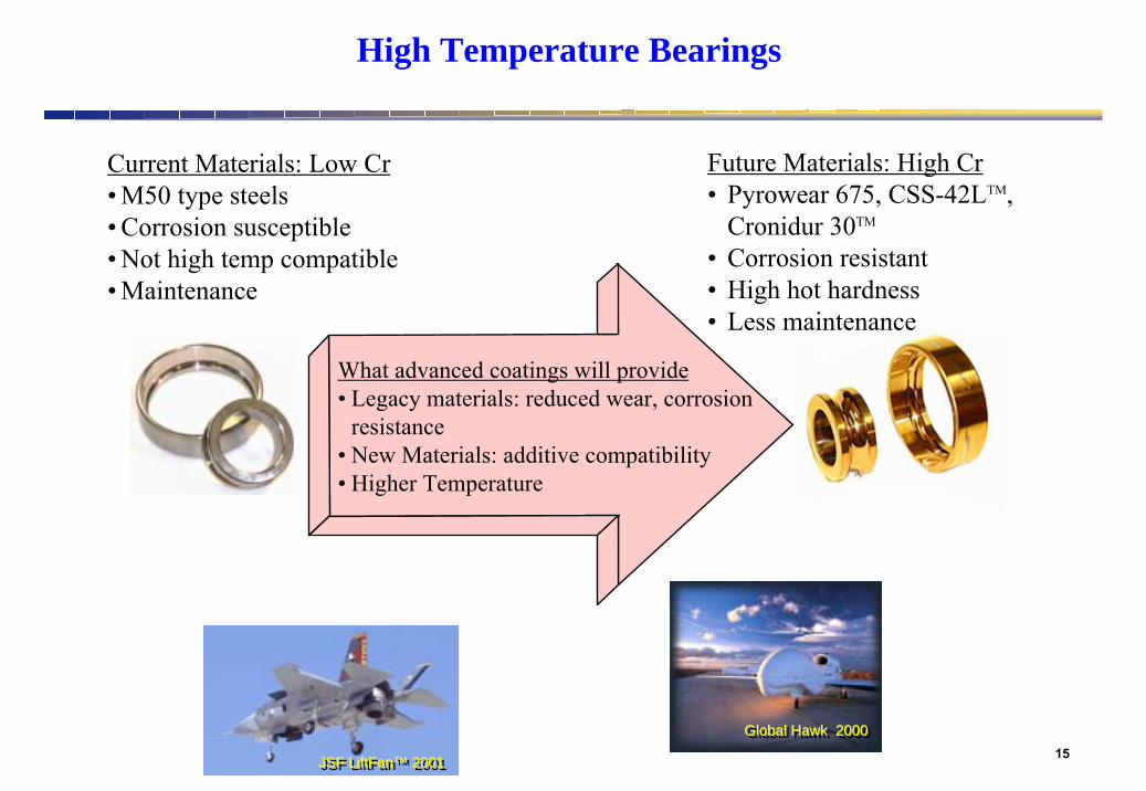
Current Materials: Low Cr• M50 type steels• Corrosion susceptible• Not high temp compatible• Maintenance
Future Materials: High Cr• Pyrowear 675, CSS-42LTM,
Cronidur 30TM
• Corrosion resistant• High hot hardness• Less maintenance
What advanced coatings will provide• Legacy materials: reduced wear, corrosion
resistance• New Materials: additive compatibility• Higher Temperature
High Temperature Bearings
Global Hawk 2000Global Hawk 2000Global Hawk 2000
JSF LiftFan™ 2001JSF JSF LiftFanLiftFan™™ 20012001
16
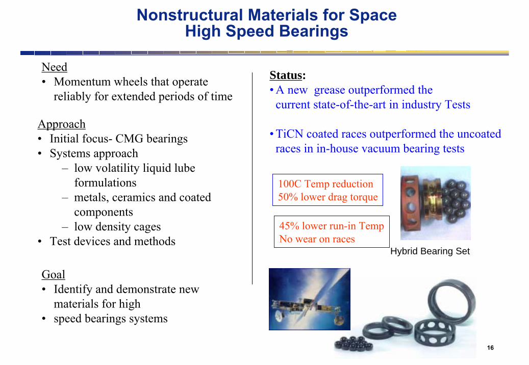
Nonstructural Materials for SpaceHigh Speed Bearings
Need• Momentum wheels that operate
reliably for extended periods of time
Goal• Identify and demonstrate new
materials for high • speed bearings systems
Approach• Initial focus- CMG bearings• Systems approach
– low volatility liquid lube formulations
– metals, ceramics and coated components
– low density cages• Test devices and methods
Status:• A new grease outperformed the current state-of-the-art in industry Tests
• TiCN coated races outperformed the uncoated races in in-house vacuum bearing tests
Hybrid Bearing Set
100C Temp reduction50% lower drag torque
45% lower run-in TempNo wear on races
17
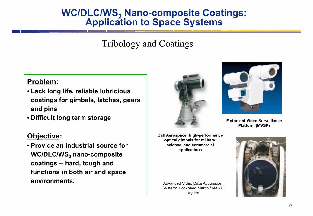
WC/DLC/WS2 Nano-composite Coatings: Application to Space Systems
Tribology and Coatings
Advanced Video Data Acquisition System: Lockheed Martin / NASA
Dryden
Motorized Video Surveillance Platform (MVSP)
Ball Aerospace: high-performance optical gimbals for military,
science, and commercial applications
Problem:• Lack long life, reliable lubricious
coatings for gimbals, latches, gears and pins
• Difficult long term storage
Objective:• Provide an industrial source for
WC/DLC/WS2 nano-composite coatings -- hard, tough and functions in both air and space environments.

18
High Cycle Fatigue: Fretting Wear Mitigation
OBJECTIVEDevelop and apply fundamental understanding of interfacial phenomena to surface preparation, coating composition and morphology in fretting fatigue conditions prevalent in turbine engines
PAYOFF• Reduced maintenance. Fretting fatigue at dovetail interfaces in compressors of turbine
engines is a major maintenance item• Increase reliable engine operating temperature (higher temperatures increase efficiency and
thrust to weight capability)• Increased flight readiness of the fleet• Increased safety margin

19
APPROACH• Define and validate effective
simulation conditions for turbine engine applications
• Systematic study of fretting mechanisms under simulated engine conditions
–Crack propagation mechanisms
–Surface chemistry/microstructure
–Temperature/environment effects
• Develop problem specific coating architectures (i.e. nanostructures, multifunctional) and procedures
• Transition to industry
Fretting Direction
50N Load
High Cycle Fatigue: Fretting Wear Mitigation

20
• Fretting wear is a destructive phenomenon which can accelerate fatigue:
• Small amplitude, high-frequency displacements between contacting surfaces.
• Developing oxides and debris are not swept away by the limited motion and grind into surface leading to damage.
• Oxide damage and surface adhesion accelerate crack initiation
• Crack growth leads to fatigue failures.
• Coatings/lubricants mitigate
surface damage phase.
What is Fretting Wear?

21
Fretting Wear Regimes• The transition between fretting wear
regimes is dependant on:
• Contact geometries
• Contact loading
• Oscillation Displacement or Stroke length
• Material
• Temperature
Wear Regime Example Plot Using Steel on Steel with
Constant Load and Varied Stroke Length
I.M. Hutchings, Tribology, Edward Arnold, a Division of Hodder Headline PLC, London 1992

22
Zou, ZR; Vincent, L…, Mixed fretting regime WearVolume: 181-183, Issue: 2 March, 1995, pp. 531-536.
Fig. 4. Number of fretting cycles to crack nucleation vs Displacement, Fn = 1000N
107
106
105
104
103
107
106
105
104
103
Cycles
Cycles
0 50 100D (+/- µm)
Sticking Regime
MFR Slip Regime
MFRSlip Regime
Sticking Regime
0 750 1500Fn (N)
Fig. 5. Number of fretting cycles to crack nucleation vs Normal force, D = +/- 35 µm.
a > 200µm
50µm < a < 200µm
a < 50µm or no crack
a > 200µm
50µm < a < 200µm
a < 50µm or no crack
When keeping the normal load constant and varying the stroke length, crack nucleation is most accelerated in the Mixed Fretting Regime
When keeping the stroke length constant and varying the normal load, crack nucleation is most accelerated in the Mixed Fretting Regime
23
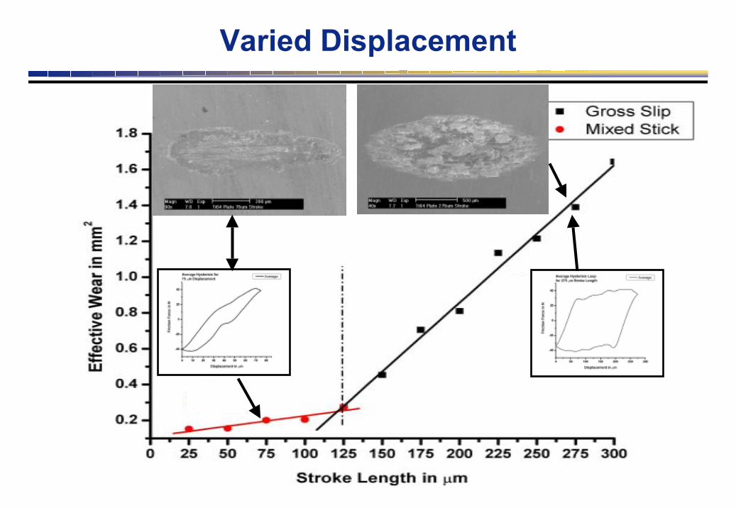
Varied Displacement

24Transition at 50N
Mixed Stick and Slip Gross Slip
25
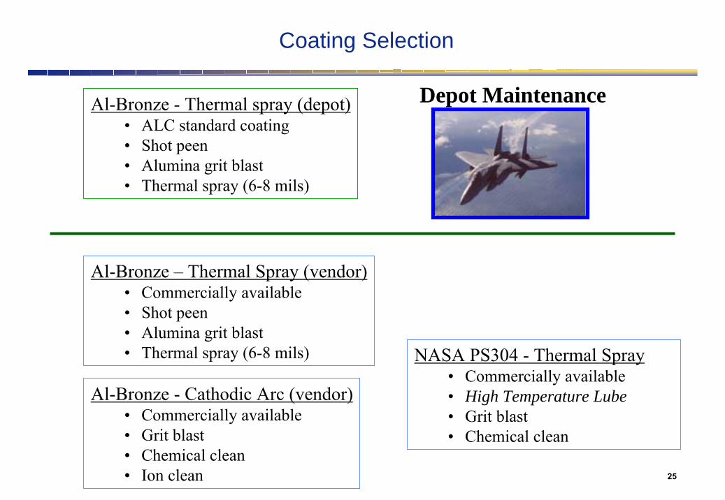
Coating Selection
Al-Bronze - Thermal spray (depot)• ALC standard coating• Shot peen• Alumina grit blast• Thermal spray (6-8 mils)
Al-Bronze - Cathodic Arc (vendor)• Commercially available• Grit blast• Chemical clean• Ion clean
Depot Maintenance
NASA PS304 - Thermal Spray• Commercially available• High Temperature Lube• Grit blast• Chemical clean
Al-Bronze – Thermal Spray (vendor)• Commercially available• Shot peen• Alumina grit blast• Thermal spray (6-8 mils)
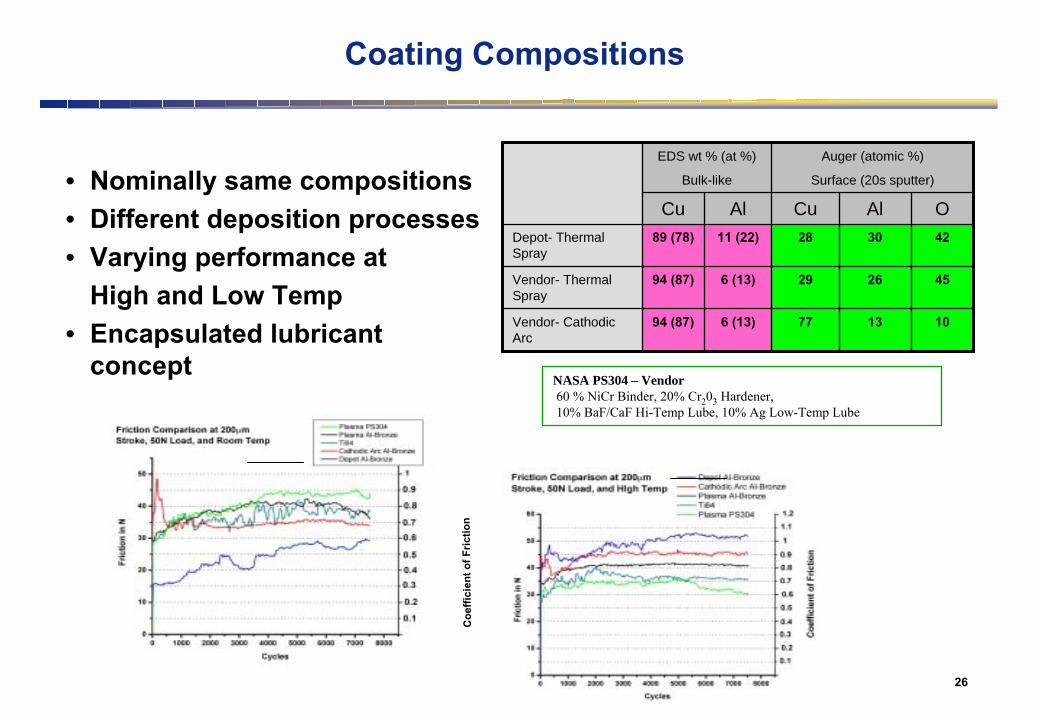
26
10
45
42
O
13776 (13)94 (87)Vendor- Cathodic Arc
26296 (13)94 (87)Vendor- Thermal Spray
302811 (22)89 (78)Depot- Thermal Spray
AlCuAlCu
Auger (atomic %)
Surface (20s sputter)
EDS wt % (at %)
Bulk-like
Coating Compositions
NASA PS304 – Vendor60 % NiCr Binder, 20% Cr203 Hardener,10% BaF/CaF Hi-Temp Lube, 10% Ag Low-Temp Lube
Coe
ffici
ent o
f Fric
tion
• Nominally same compositions• Different deposition processes• Varying performance at
High and Low Temp• Encapsulated lubricant
concept

27
Mating Ti6Al4V: Fretting Scar in Gross Slip, Room Temperature
28
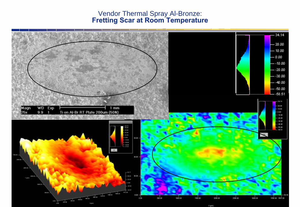
Vendor Thermal Spray Al-Bronze: Fretting Scar at Room Temperature

29
Uncoated• Severe galling of Ti6Al4• Wear regime a function of cycles, adhesive junctions fatigue and can produce
excessive wear debris • Mixed fretting regime can cause localized surface bonding of Ti64 surfaces
Coatings• Coatings dramatically reduce the galling• Al-Bronze coatings are not all alike
– At RT• Depot coating had lowest friction• Vendor coating had less severe wear
– At 450 C• Vendor coating had lowest friction and less severe wear• Auger indicates an increase in Al oxide for the depot coating
• Imbedded lubricant may reduce fretting wear (ex. NASA PS304)
Anti-fretting Coatings Summary

30
Nanotechnologies in MEMS
Nanotribology of MEMSFriction, stiction, and wear prevent operation of some MEMS devices and limit performance and design of others - nanotechnologies required for solution
• Nanostructured coatings• Low friction wear resistant self-healing, self-assembled monolayers (SAMS)• Replenishable gas phase lubrication• Modify surface forces / chemistry to enable reliable MEMS in Aerospace environments• Fundamental nanometer scale tribological and device reliability studies
Property Enhancements• Enable operation in extreme environments (e.g., space, humidity, high temperature)• Reduce/eliminate wear and stiction• Reduce friction - decrease energy consumption, increase dynamic range• Prevent electrical contact degradation• Surface treatments compatible with MEMS processing
Microelectromechanical SystemsNanotribology of MEMS
Mobile self-healing phaseBound wear resistant SAM
~1-5 nm
MEMS gear train
~50 µm
Functionality
Bonding
Surface energy/friction control
mechanicalSandia

31
Satellites & Space Systems
• Enable MEMS operation in space (reduce/eliminate friction and wear)
• Increase capability• Integrate and miniaturize sensing and actuation• Reduce cost (lower weight)• Increase reliability (e.g., distributed satellites)• Enable phased arrays for microwave
communications and radar
• Improve aerodynamics• Embedded health monitoring
ImpactNanotribology of MEMS
Weapons
• Impact and shock resistant guidance systems• Health monitoring
Aircraft
Switch array
32
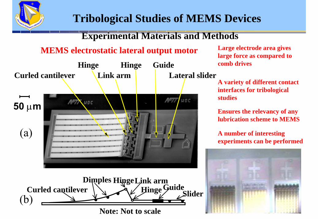
Tribological Studies of MEMS DevicesExperimental Materials and Methods
MEMS electrostatic lateral output motor
50 µm
Curled cantileverHinge
Lateral sliderGuide
Link armHinge
(a)
Curled cantileverHinge
GuideSlider
Dimples
Note: Not to scale
Link armHinge
(b)
Large electrode area gives large force as compared to comb drives
A variety of different contact interfaces for tribological studies
Ensures the relevancy of any lubrication scheme to MEMS
A number of interesting experiments can be performed

33
0100200300400500600700800900
A B C DCoating conditions
Ave
rage
tim
e (m
in.)
to fa
ilure
Optimization of Zdol Coating
A. UncoatedB. 0.1%, 175o
C, 1h.C. 0.2%, 175 oC, 1h.D. 0.1%, 150 o
C, 1h.
Tribological Studies of MEMS Devices
HOCH2CF2(OCF2)m(OCF2CF2)nOCF2CH2OH
Z-dol Approx.. mol. wt. 2000
DRY AIR

34
Performance of DLC (~ 5 nm) coated MEMS motors
0
500
1000
1500
2000
2500
Uncoated DLC
Ave
rage
Life
(min
utes
)
Std. Dev.Average
Room T, < 3% RH6 Run minimum1 KHz, 0 to 100 V
Si
110 nm 30 nm
Tribological Studies of MEMS Devices

35
MEMS RF Switch Tribology
Types of MEMS switches
DC• DC-6 GHz• metal-to-metal contact (Au on Au)• failure mechanisms include
adhesion, melting, loss of electrical contact, etc.
RF in RF out
Contacts
Capacitive• ≥ 10 GHz• metal-to-dielectric contact (Au on
silicon nitride)• failure mechanisms include
adhesion and dielectric charging
RF in RF outContact

36
Experimental Materials and MethodsSchematic of the micro/nanoadhesion apparatus
Bridges the gap between macrotribology and nanotribology Versatile ball-on-flat configuration
MEMS RF Switch Tribology
Movable platformX-micrometer stageY-micrometer stage
Piezoelectric actuator
xy
z
Ball holder
BallInsulating waferholder
Load cell (LVDT)
Wafer
Tilt stage (y-z plane)
Thermohygrometer
Vent
Environmental chamber
signal
Actuator
A to D converter
input signal Signal
generator
Adhesion Signal conditioner
Computer
Tilt stage (x-z plane)PlateFoamBase
Insulating coupler
CurrentsourceContact resistance circuit

37
Tribological Studies of MEMS Devices
Switch durability at various currents in air
The inability to reliably switch upon demand is taken to be failure
1
10
100
1000
10 4
105
10 6
0.001 0.01 0.1 1 10Current (mA)
Num
ber
of c
ycle
s to
failu
re
No failure
Failure by intermittent shorting
Adhesion concerns
5 Hz, ~ 100 µN
38
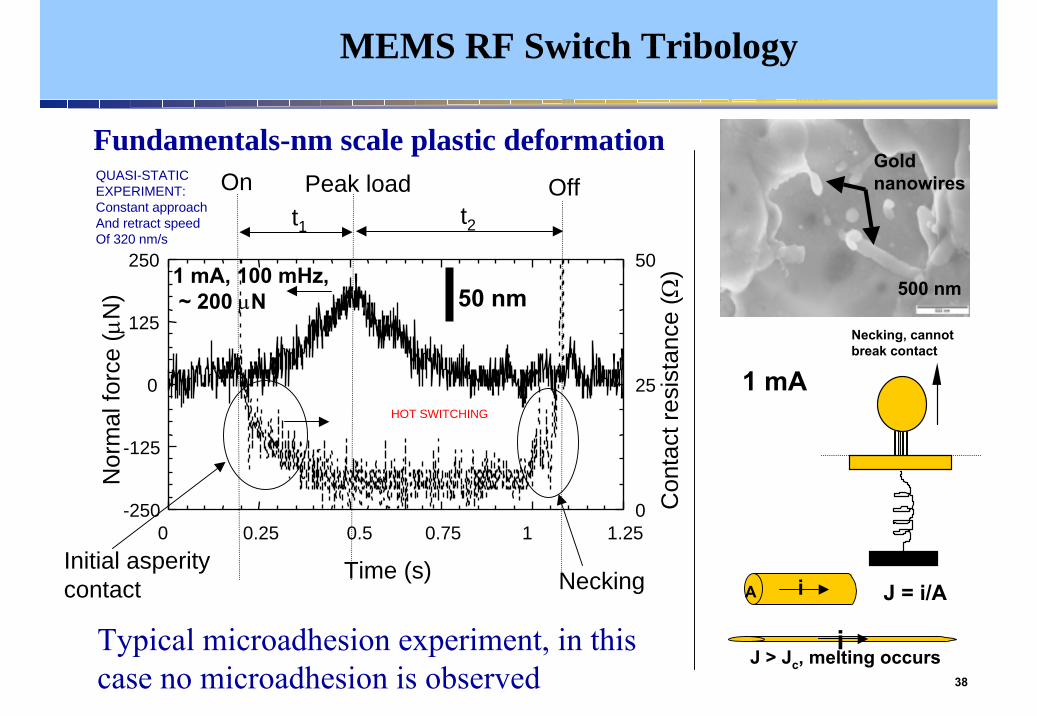
MEMS RF Switch Tribology
-250
-125
0
125
250
0
25
50
0 0.25 0.5 0.75 1 1.25
Time (s)
Nor
mal
forc
e (µ
N)
Con
tact
resi
stan
ce (Ω
)
On OffPeak load
Initial asperitycontact Necking
t1 t2
1 mA, 100 mHz,~ 200 µN 50 nm
Fundamentals-nm scale plastic deformation
Typical microadhesion experiment, in this case no microadhesion is observed
QUASI-STATIC EXPERIMENT:Constant approachAnd retract speed Of 320 nm/s
HOT SWITCHING
500 nm
Gold nanowires
Necking, cannot break contact
J = i/AiA
iJ > Jc, melting occurs
1 mA

39
MEMS Summary
• MEMS device applications are on the increase
• Lubrication issues will limit the use of many complex devices
• Monolayer treatments and coatings can dramatically increase reliability and durability
• It is important and challenging to understand failure mechanisms at the nano-level
• Surface engineered solutions will have to be developed for particular applications (ex. Switches)

40
Specialty Coatings and Treatments: Tamper Resistance
• Prevent technology transfer, alteration of system capability, and development of counter-measures
• Current external coatings damage underlying electronic components and/or affect reliability
• Need to develop coatings and circuit board constructions from advanced materials technologies
41
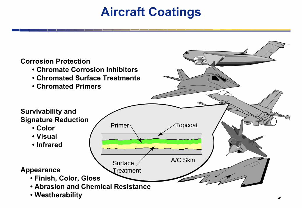
Aircraft Coatings
Corrosion Protection• Chromate Corrosion Inhibitors • Chromated Surface Treatments• Chromated Primers
Survivability andSignature Reduction
• Color• Visual• Infrared
Appearance• Finish, Color, Gloss• Abrasion and Chemical Resistance• Weatherability
Primer
SurfaceTreatment
A/C Skin
Topcoat

42
DURABLE TOPCOATS:Low optical and near-infrared gloss;UV & hydrolysis resistance;Non-porous barrier protection.NEED: Greater exterior durability to maintain physical and optical properties.
PERMANENT PRIMER:Excellent adhesion to substrate;Very good barrier properties to corrosives;Delivery system for corrosion inhibitors.NEED: Lifetime resistance to environmental degradation, chromate free corrosion protection and NDE capability.
SURFACE TREATMENT:Strong chemical bond to substrate;Provides surface tailored for adhesion;Mechanism for inhibitor incorporation.NEED: Environmentally benign treatments compatible with chromate free systems.
= Chromate Free Inhibitor = NDE Chromophore
Aircraft Coating System Requirements / Needs

43
Aircraft Paint Materials and Processes Advanced Aircraft Coatings Program
Mid Term Program: focused on tech transition
• Goal: Topcoat performance through PDM Cycle
topcoat lab tests: 8X durability increase
• Goal: Reduction in use of Chromates
“Boegel” nonchromate surface treatments
Long Term Program: high performance corrosion prevention
• Goal: Revolutionary materials: Protection for 30+ yr.
Permanent Primer Program
– Functionalized sol-gel surface treatments
– High durability resins, tailored pigments and inhibitors
44
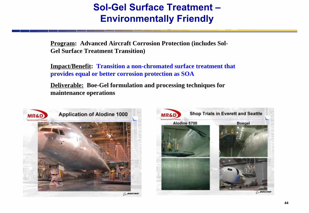
Program: Advanced Aircraft Corrosion Protection (includes Sol-Gel Surface Treatment Transition)
Impact/Benefit: Transition a non-chromated surface treatment that provides equal or better corrosion protection as SOA
Deliverable: Boe-Gel formulation and processing techniques for maintenance operations
Sol-Gel Surface Treatment –Environmentally Friendly

45
Self-assembled Nanophase Particle (SNAP) Coatings
Functionalized Nanoparticle
bulk Al alloyAl oxide layer
1.8 nm
• SNAP is an epoxide based system– GPTMS, TMOS precursors
• Siloxane “oligomers” form in aqueous soln.– <5nm diameter, 1,500 amu
• Coating forms by crosslinking oligomers– water based process (synthesis and application)– residual alcohol removed
• Thin, dense coatings – barrier to corrosion• Room temperature cure - primary amine catalyst• Zero HAPS, low VOC’s,
Cross-section SEM image of SNAP coating on AA2024-T3 substrate
Dense, defect-free ~1 micron film with excellent adhesion and barrier properties for use as surface treatment.
Nanostructured Materials Sciencefor Aerospace Coatings
46
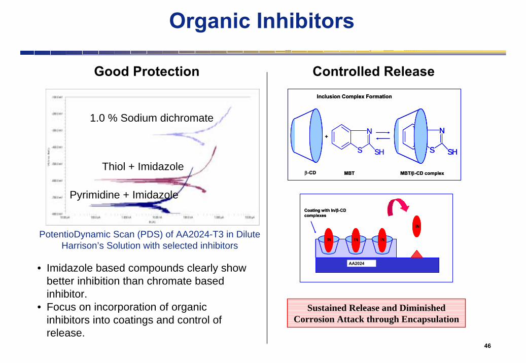
• Imidazole based compounds clearly show better inhibition than chromate based inhibitor.
• Focus on incorporation of organic inhibitors into coatings and control of release.
Organic Inhibitors
1.0 % Sodium dichromate
Thiol + Imidazole
Pyrimidine + Imidazole
PotentioDynamic Scan (PDS) of AA2024-T3 in Dilute Harrison’s Solution with selected inhibitors
N
S SH
N
S SH
+
β-CD MBT MBT/β-CD complex
Inclusion Complex Formation
N
S SH
N
S SH
N
S SH
+
β-CD MBT MBT/β-CD complex
Inclusion Complex Formation
IN
IN IN IN
Coating with In/β-CD complexes
AA2024
IN
ININ ININ IN
Coating with In/β-CD complexes
AA2024
Sustained Release and Diminished Corrosion Attack through Encapsulation
Good Protection Controlled Release
47
ANODICAREA
1
CATHODICAREA
2
4 ELECTRON CONDUCTOR (METAL)
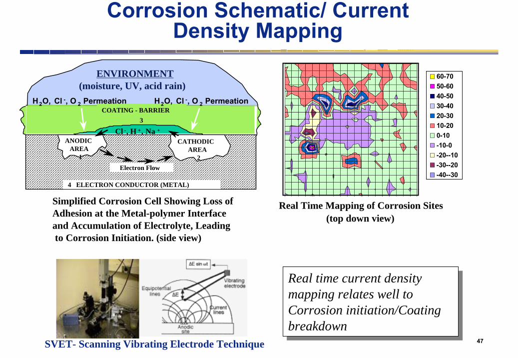
ENVIRONMENT(moisture, UV, acid rain)
Electron Flow
Simplified Corrosion Cell Showing Loss of
and Accumulation of Electrolyte, LeadingAdhesion at the Metal-polymer Interface
to Corrosion Initiation. (side view)
COATING - BARRIER
Cl -, H +, Na +
H2O, Cl -, O 2 Permeation
3
H2O, Cl -, O 2 Permeation
Real time current density mapping relates well to Corrosion initiation/Coating breakdown
Real time current density mapping relates well to Corrosion initiation/Coating breakdown
Real Time Mapping of Corrosion Sites(top down view)
60-7050-6040-5030-4020-3010-200-10-10-0-20--10-30--20-40--30
Corrosion Schematic/ Current Density Mapping
SVET- Scanning Vibrating Electrode Technique

48
Camouflage Coating Microstructure
4 mil
1 mil
CamouflageTopcoat
Primer
Substrate
Coating Composition
• Polyurethane resin binder
• Inorganic pigments for surface roughness and color
• Solvents for processability and final film build
Optical Signature Mechanisms
• Rough surface reflects and scatters light
• Carbon based pigments absorb some visible and NIR

49
COMPONENT SURFACE TREATMENTSDefinition
Mechanical Processes That:
• Generate Compressive Residual Stresses• Improve Surface Finish• Improve Surface Hardness• Etc.

50
COMPONENT SURFACE TREATMENTSProcessing Methods
• Laser Shock Processing (LSP)*
• Low Plasticity Burnishing (LPB)
• Shot Peening*
• Gravity Peening*
• Mass Media Finishing (Tumbling)*
• Roller Burnishing*
• Split Sleeve Cold Expansion*
• Ultrasonic Peening (USP)
• Waterjet (Cavitation) Peening
• Cold Rolling*
• Laser Shock Processing (LSP)*
• Low Plasticity Burnishing (LPB)
• Shot Peening*
• Gravity Peening*
• Mass Media Finishing (Tumbling)*
• Roller Burnishing*
• Split Sleeve Cold Expansion*
• Ultrasonic Peening (USP)
• Waterjet (Cavitation) Peening
• Cold Rolling*
LPB
LSP
51
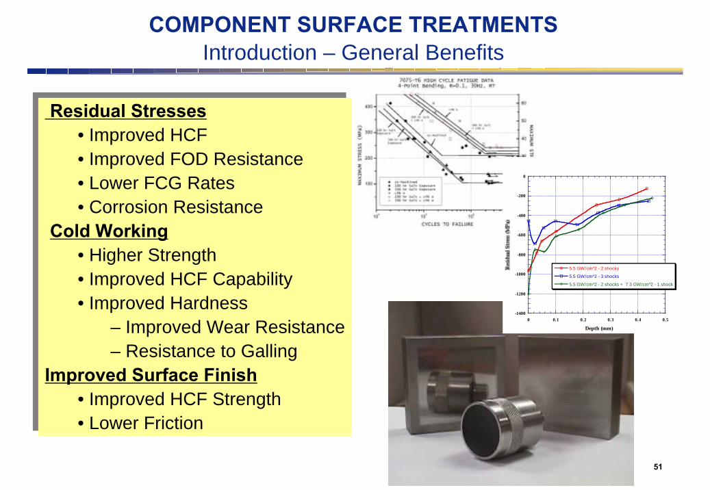
COMPONENT SURFACE TREATMENTSIntroduction – General Benefits
Residual Stresses• Improved HCF• Improved FOD Resistance • Lower FCG Rates• Corrosion Resistance
Cold Working• Higher Strength• Improved HCF Capability• Improved Hardness
– Improved Wear Resistance– Resistance to Galling
Improved Surface Finish• Improved HCF Strength• Lower Friction
Residual Stresses• Improved HCF• Improved FOD Resistance • Lower FCG Rates• Corrosion Resistance
Cold Working• Higher Strength• Improved HCF Capability• Improved Hardness
– Improved Wear Resistance– Resistance to Galling
Improved Surface Finish• Improved HCF Strength• Lower Friction
-1400
-1200
-1000
-800
-600
-400
-200
0
0 0.1 0.2 0.3 0.4 0.5
5.5 GW/cm^2 - 2 shocks
5.5 GW/cm^2 - 3 shocks
5.5 GW/cm^2 - 2 shocks + 7.3 GW/cm^2 - 1 shock
Depth (mm)

52
Improve DesignsImprove an existing design with inadequate margin• Current fan blade leading edge applications
Enable Aggressive DesignsEnable new designs and materials to meet FOD Requirements• Forward swept fan designs• Gamma TiAl structures
Extend LifeIncorporation of residual stresses into design calculations • Slower FCG projections = longer damage tolerant design lives
RepairImprove residual stress state or bury damage in compression• Fretting zones / weld repair
COMPONENT SURFACE TREATMENTSIntroduction - Applications

53
COMPONENT SURFACE TREATMENTSHistory - Fan Blade Leading Edge Applications
Current Production Status• Laser Shock Processing moved quickly
into production
Current Production Status• Laser Shock Processing moved quickly
into production
Background:• Early-Mid 90’s - fan blade failures in engines were seen
– Time consuming “thumb nail” inspections implemented– “thumb nail” inspection every 25 flight hours– “thumb nail” inspection prior to 1st flight of day
• Millions of $ in personnel costs associated with these inspections
• 90% of failures from cracks of < 125 mils
• Small foreign object damage (FOD) coincides with high stress regions
• Laser shock processing can completely mitigate small FOD• Allows strictly visual inspection

54
COMPONENT SURFACE TREATMENTSLaser Shock Processing (LSP) Process Schematic
Laser Shock Processing (LSP)• A shock process, NOT thermal
• Laser vaporizes ablative medium, generating a shockwave constrained by a transparent overlay
• The shock wave travels into the workpiece, plastically deforming the treated region
• Deformed material is constrained by surrounding undeformed material
• Generates deep, high magnitude compressive stresses (1mm+)
LASER BEAM
SHOCK WAVE
VAPOR PRESSURE
WATER CURTAIN(transparent overlay)
Part
PAINT(ablative medium)

55
COMPONENT SURFACE TREATMENTSLaser Shock Processing (LSP) - Movie
LSPBlade Edge Damage Tolerance Application
F119 4th Stage Compressor
56
COMPONENT SURFACE TREATMENTSLaser Shock Processing Movie – MIC/LLNL

57
Surface Treatments and FrettingLow Plasticity Burnishing Process
Low Plasticity Burnishing (LPB)• Essentially a CNC machining operation
• Surface is plastically deformed by a free rolling ball supported in a fluid bearing
• Process minimizes cold work
• Deformed material is constrained by surrounding undeformed material
• Generates deep, high magnitude compressive stresses (1mm+)
LAMBDARESEARCH

58
Surface Treatments and FrettingLow Plasticity Burnishing Process
LPBLeading Edge Damage Tolerance Application
Low Bypass Military Fan Blade LAMBDARESEARCH

59
COMPONENT SURFACE TREATMENTSPotential Drawbacks
• Residual Stresses• Compensatory Tensile Stresses
• Loss of Tolerance
• Surface / Subsurface Damage - shot peening surface damage- delamination due to LSP
• Processing Variability
• Cold Working• Loss of Toughness
• Added Cost
• Residual Stresses• Compensatory Tensile Stresses
• Loss of Tolerance
• Surface / Subsurface Damage - shot peening surface damage- delamination due to LSP
• Processing Variability
• Cold Working• Loss of Toughness
• Added Cost
35 dB
Lead Tape
-800
-700
-600
-500
-400
-300
-200
-100
0
100
0 0.05 0.1 0.15 0.2
6-9N Trial #16-9N Trial #26-9N Trial #3

60
Surface Engineering Summary
•Many applications for surface engineered materials across air and space platforms
•Examples of applications and processes–Nanocomposite coatings: reduce friction and wear across multiple and/or extreme environments
–Bearing components–Fretting wear mitigation–MEMS contacts–Surface treatments, primers and paints–Laser shock processing–Low plasticity burnishing
•Demands for surface engineering will increase to accommodate future concepts to go faster and farther at anytime and anywhere
Thank You !!!
Recommended