API TECHNOLOGIES • 8061 Avonia Rd. • Fairview, PA 16415 • Ph: 814-474-1571 • Fax: 814-474-3110 • eis.apitech.comAPI TECHNOLOGIES’ SPECTRUM CONTROL GmbH • Hansastrasse 6 • 91126 Schwabach, Germany • Phone: (49)-9122-795-0 • Fax: (49)-9122-795-58
SM1
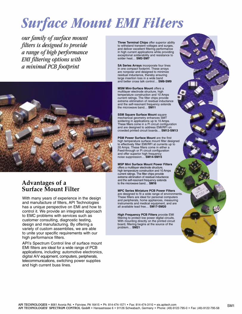
our family of surface mountfilters is designed to provide a range of high performanceEMI filtering options with a minimal PCB footprint
With many years of experience in the designand manufacture of filters, API Technologieshas a unique perspective on EMI and how tocontrol it. We provide an integrated approachto EMC problems with services such as customer consulting, diagnostic testing,design and manufacturing. By offering a variety of custom assemblies, we are able to unite your specific requirements with ourhigh performance filters.
API’s Spectrum Control line of surface mountEMI filters are ideal for a wide range of PCBapplications, including: automotive electronics,digital A/V equipment, computers, peripherals, telecommunications, switching power suppliesand high current buss lines.
Advantages of a Surface Mount Filter
Surface Mount EMI Filters
MSM Mini-Surface Mount offers a multilayer electrode structure, high temperature construction and 10 Amps current ratings. The filter chips provideextreme elimination of residual inductanceand the self-resonant frequency extends the microwave band… SM11
SA Series Arrays incorporate four lines in one compact footprint. These arrays are nonpolar and designed to minimize residual inductance, thereby ensuring large insertion loss in a wide band and better cross talk control… SM8-SM9
PSM Power Surface Mount are the first high temperature surface mount filter designedto effectively filter EMI/RFI at currents up to 20 Amps. These filters come in either a Feed-through or Pi circuit configuration and offer superior high frequency noise suppression… SM14-SM15
SSM Square Surface Mount square mechanical geometry enhances SMT soldering in applications up to 10 Amps. These filters come in a Pi circuit configurationand are designed to address EMI/RFI oncrowded printed circuit boards… SM12-SM13
Three Terminal Chips offer superior ability to withstand transient voltages and surges,and deliver excellent filtering performance in high current applications while providing exceptional solderability and resistance to solder heat… SM2-SM7
MSP Mini Surface Mount Power Filters offers a multilayer electrode structure, high temperature construction and 10 Amps current ratings. The filter chips provide extreme elimination of residual inductance and the self-resonant frequency extends to the microwave band… SM16
High Frequency PCB Filters provide EMI filtering to protect low power digital circuits.With mounting directly on the printed circuitboard, filtering begins at the source of theproblem… SM21
MPC Series Miniature PCB Power Filters are designed to fit a wide range of environments.These filters are ideal for personal computers and peripherals, home appliances, measuringinstruments and medical equipment, and are all available lead free… SM17-SM20
API TECHNOLOGIES • 8061 Avonia Rd. • Fairview, PA 16415 • Ph: 814-474-1571 • Fax: 814-474-3110 • eis.apitech.comAPI TECHNOLOGIES’ SPECTRUM CONTROL GmbH • Hansastrasse 6 • 91126 Schwabach, Germany • Phone: (49)-9122-795-0 • Fax: (49)-9122-795-58
Surface Mount EMI Filters
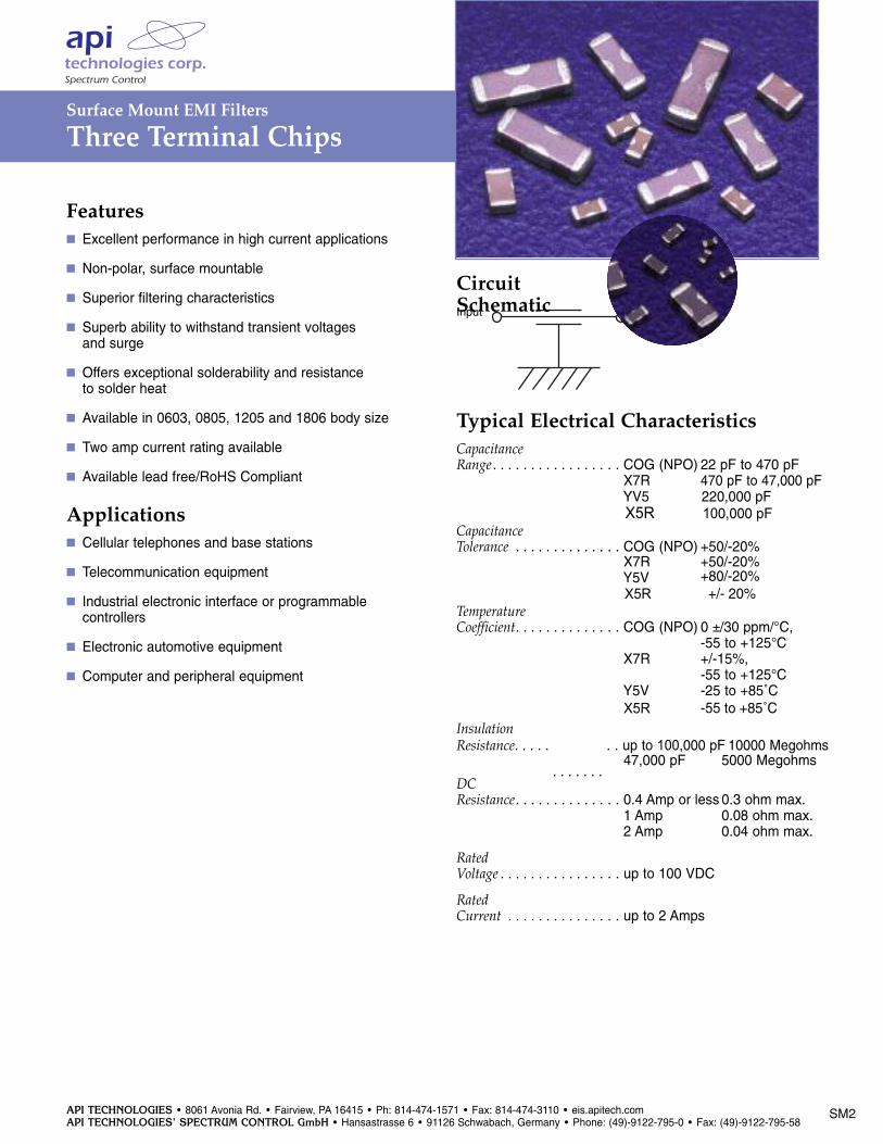
Three Terminal Chips
Features Excellent performance in high current applications
Non-polar, surface mountable
Superior filtering characteristics
Superb ability to withstand transient voltages and surge
Offers exceptional solderability and resistance to solder heat
Available in 0603, 0805, 1205 and 1806 body size
Two amp current rating available
Available lead free/RoHS Compliant
Applications Cellular telephones and base stations
Telecommunication equipment
Industrial electronic interface or programmable controllers
Electronic automotive equipment
Computer and peripheral equipment
Typical Electrical CharacteristicsCapacitanceRange . . . . . . . . . . . . . . . . . COG (NPO) 22 pF to 470 pF. . . . . . . . . . . . . . . . . . . . . X7R 470 pF to 47,000 pF. . . . . . . . . . . . . . . . . . . . . YV5 220,000 pF
CapacitanceTolerance . . . . . . . . . . . . . . COG (NPO) +50/-20%. . . . . . . . . . . . . . . . . . . . . X7R +50/-20%. . . . . . . . . . . . . . . . . . . . . Y5V +80/-20%
TemperatureCoefficient. . . . . . . . . . . . . . COG (NPO) 0 ±/30 ppm/°C,. . . . . . . . . . . . . . . . . . . . . -55 to +125°C. . . . . . . . . . . . . . . . . . . . . X7R +/-15%, . . . . . . . . . . . . . . . . . . . . . -55 to +125°C. . . . . . . . . . . . . . . . . . . . . Y5V -25 to +85˚C
InsulationResistance. . . . .
. . . . . . .
. . up to 100,000 pF 10000 Megohms. . . . . . . . . . . . . . . . . . . . . 47,000 pF 5000 Megohms
DCResistance. . . . . . . . . . . . . . 0.4 Amp or less 0.3 ohm max.. . . . . . . . . . . . . . . . . . . . . 1 Amp 0.08 ohm max.. . . . . . . . . . . . . . . . . . . . . 2 Amp 0.04 ohm max.
Rated Voltage . . . . . . . . . . . . . . . . up to 100 VDC
Rated Current . . . . . . . . . . . . . . . up to 2 Amps
Input
CircuitSchematic
SM2
. . . . . . . . . . . . . . . . . . . . . X5R 100,000 pF
. . . . . . . . . . . . . . . . . . . . . X5R -55 to +85˚C
. . . . . . . . . . . . . . . . . . . . .X XX5R +/- 20%
API TECHNOLOGIES • 8061 Avonia Rd. • Fairview, PA 16415 • Ph: 814-474-1571 • Fax: 814-474-3110 • eis.apitech.comAPI TECHNOLOGIES’ SPECTRUM CONTROL GmbH • Hansastrasse 6 • 91126 Schwabach, Germany • Phone: (49)-9122-795-0 • Fax: (49)-9122-795-58
SM3
Surface Mount EMI Filters
Three Terminal Chips
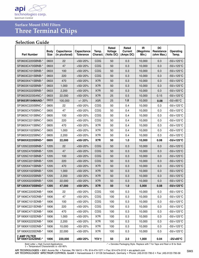
Selection Guide
Bold Letter = High Current Applications -* = Denotes Packaging Style. Replace with T for Tape and Reel or B for Bulk† = Temperature Characteristic is +30/-80%
Rated Rated IR DCBody Capacitance Capacitance Temp. Voltage Current (Megohms Resistance Operating
Part Number Size (in picofarad) Tolerance Charact. (Volts DC) (Amps DC) Min.) (ohm Max.) Temp.
SF0603C220SBNB-* 0603 22 +50/-20% COG 50 0.3 10,000 0.3 -55/+125°C
SF0603C470SBNB-* 0603 47 +50/-20% COG 50 0.3 10,000 0.3 -55/+125°C
SF0603C101SBNB-* 0603 100 +50/-20% COG 50 0.3 10,000 0.3 -55/+125°C
SF0603C221SBNB-* 0603 220 +50/-20% COG 50 0.3 10,000 0.3 -55/+125°C
SF0603X471SBNB-* 0603 470 +50/-20% X7R 50 0.3 10,000 0.3 -55/+125°C
SF0603X102SBNB-* 0603 1,000 +50/-20% X7R 50 0.3 10,000 0.3 -55/+125°C
SF0603X222SBNB-* 0603 2,200 +50/-20% X7R 50 0.3 10,000 0.3 -55/+125°C
SF0603X223SANC-* 0603 22,000 +50/-20% X7R 25 0.5 10,000 0.15 -55/+125°C
SF0805C220SBNC-* 0805 22 +50/-20% COG 50 0.4 10,000 0.3 -55/+125°C
SF0805C470SBNC-* 0805 47 +50/-20% COG 50 0.4 10,000 0.3 -55/+125°C
SF0805C101SBNC-* 0805 100 +50/-20% COG 50 0.4 10,000 0.3 -55/+125°C
SF0805C221SBNC-* 0805 220 +50/-20% COG 50 0.4 10,000 0.3 -55/+125°C
SF0805X471SBNC-* 0805 470 +50/-20% X7R 50 0.4 10,000 0.3 -55/+125°C
SF0805X102SBNC-* 0805 1,000 +50/-20% X7R 50 0.4 10,000 0.3 -55/+125°C
SF0805X222SBNC-* 0805 2,200 +50/-20% X7R 50 0.4 10,000 0.3 -55/+125°C
SF0805X223SBND-* 0805 22,000 +50/-20% X7R 50 1.0 10,000 0.08 -55/+125°CSF1205C220SBNB-* 1205 22 +50/-20% COG 50 0.3 10,000 0.3 -55/+125°C
SF1205C470SBNB-* 1205 47 +50/-20% COG 50 0.3 10,000 0.3 -55/+125°C
SF1205C101SBNB-* 1205 100 +50/-20% COG 50 0.3 10,000 0.3 -55/+125°C
SF1205C221SBNB-* 1205 220 +50/-20% COG 50 0.3 10,000 0.3 -55/+125°C
SF1205X471SBNB-* 1205 470 +50/-20% X7R 50 0.3 10,000 0.3 -55/+125°C
SF1205X102SBNB-* 1205 1,000 +50/-20% X7R 50 0.3 10,000 0.3 -55/+125°C
SF1205X222SBNB-* 1205 2,200 +50/-20% X7R 50 0.3 10,000 0.3 -55/+125°C
SF1205X223SBNB-* 1205 22,000 +50/-20% X7R 50 0.3 10,000 0.3 -55/+125°C
SF1205X473SBND-* 1205 47,000 +50/-20% X7R 50 1.0 5,000 0.08 -55/+125°CSF1806C220SDNB-* 1806 22 +50/-20% COG 100 0.3 10,000 0.3 -55/+125°C
SF1806C470SDNB-* 1806 47 +50/-20% COG 100 0.3 10,000 0.3 -55/+125°C
SF1806C101SDNB-* 1806 100 +50/-20% COG 100 0.3 10,000 0.3 -55/+125°C
SF1806C221SDNB-* 1806 220 +50/-20% COG 100 0.3 10,000 0.3 -55/+125°C
SF1806C471SDNB-* 1806 470 +50/-20% COG 100 0.3 10,000 0.3 -55/+125°C
SF1806X102SDNB-* 1806 1,000 +50/-20% X7R 100 0.3 10,000 0.3 -55/+125°C
SF1806X222SDNB-* 1806 2,200 +50/-20% X7R 100 0.3 10,000 0.3 -55/+125°C
SF1806X103SDNB-* 1806 10,000 +50/-20% X7R 100 0.3 10,000 0.3 -55/+125°C
SF1806X223SDNB-* 1806 22,000 +50/-20% X7R 100 0.3 10,000 0.3 -55/+125°C
2 AMP FILTERSF1806Y224ZBNE-* 1806 220,000 +80/-20% Y5V † 50 2.0 1,000 0.04 -25/+85°C
SF0603R104MAND-* 0603 100,000 +/- 20% X5R 25 1.0 10,000 0.08 -55/+85°C
API TECHNOLOGIES • 8061 Avonia Rd. • Fairview, PA 16415 • Ph: 814-474-1571 • Fax: 814-474-3110 • eis.apitech.comAPI TECHNOLOGIES’ SPECTRUM CONTROL GmbH • Hansastrasse 6 • 91126 Schwabach, Germany • Phone: (49)-9122-795-0 • Fax: (49)-9122-795-58
Surface Mount EMI Filters
Three Terminal Chips
SM4
70
60
50
40
30
20
10
01 10 100
Frequency (MHz)1000
801 Amp
Inse
rtio
n L
oss
(d
B)
22,000
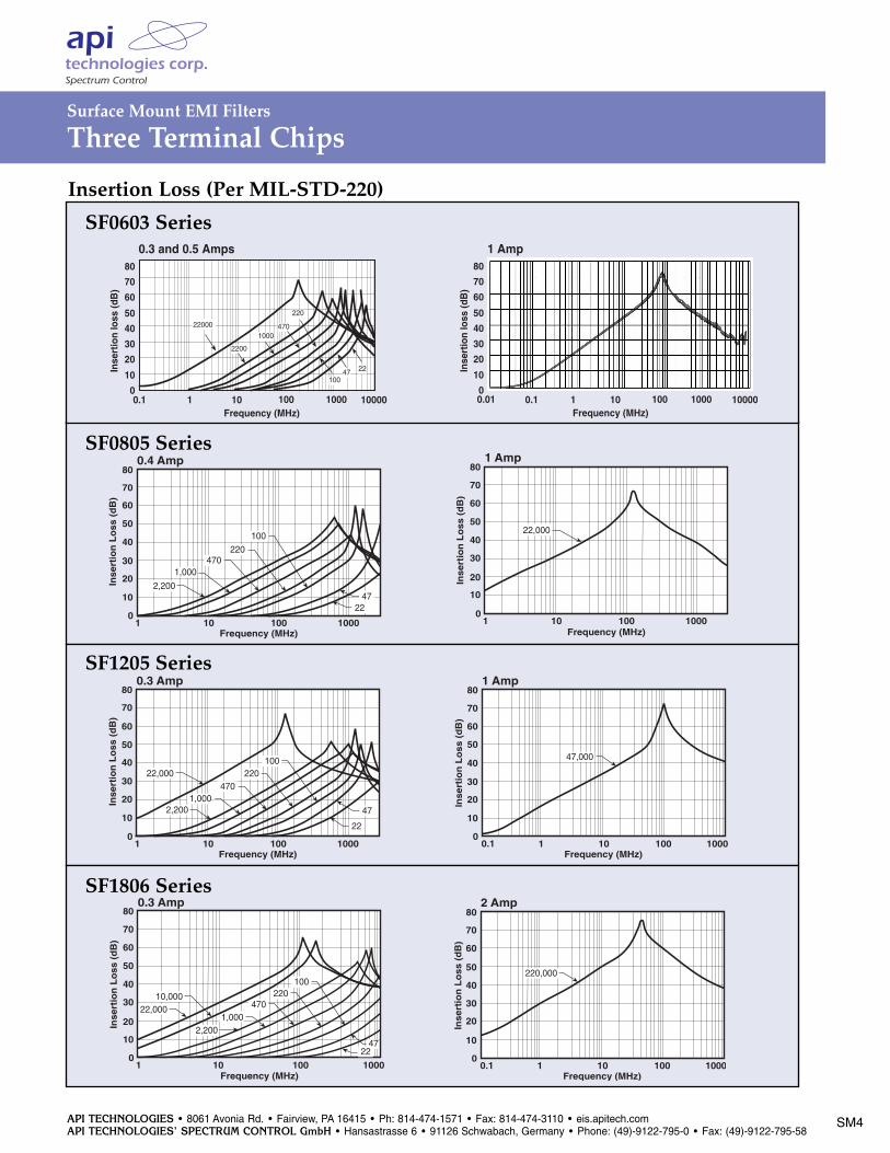
Insertion Loss (Per MIL-STD-220)
SF1205 Series
SF1806 Series
70
60
50
40
30
20
10
00.1 1 10 100
Frequency (MHz)1000
801 Amp
Inse
rtio
n L
oss
(d
B)
47,000
70
60
50
40
30
20
10
00.1 1 10 100
Frequency (MHz)1000
802 Amp
Inse
rtio
n L
oss
(d
B)
220,000
70
60
50
40
30
20
10
01 10 100
Frequency (MHz)1000
800.4 Amp
Inse
rtio
n L
oss
(d
B)
470
2,200
1,000
220
100
4722
70
60
50
40
30
20
10
01 10 100
Frequency (MHz)1000
80
2,2001,000
470220
100
47
22
0.3 Amp
Inse
rtio
n L
oss
(d
B)
22,000
70
60
50
40
30
20
10
01 10 100
Frequency (MHz)1000
80
2,2001,000
470220
100
4722
22,00010,000
0.3 Amp
Inse
rtio
n L
oss
(d
B)
SF0805 Series
Inse
rtio
n lo
ss (d
B)
Frequency (MHz)
0.3 and 0.5 Amps
0.1 1 10 10000
50
0
80
70
60
40
30
20
10
100 1000
2200
22000
1000
220
470
10047 22 In
sert
ion
loss
(dB
)
Frequency (MHz)
1 Amp
0.1 1 10 10000
50
0
80
70
60
40
30
20
10
100 10000.01
Inse
rtio
n lo
ss (d
B)
Frequency (MHz)
0.3 and 0.5 Amps
0.1 1 10 10000
50
0
80
70
60
40
30
20
10
100 1000
2200
22000
1000
220
470
10047 22 In
sert
ion
loss
(dB
)
Frequency (MHz)
1 Amp
0.1 1 10 10000
50
0
80
70
60
40
30
20
10
100 10000.01
SF0603 Series
API TECHNOLOGIES • 8061 Avonia Rd. • Fairview, PA 16415 • Ph: 814-474-1571 • Fax: 814-474-3110 • eis.apitech.comAPI TECHNOLOGIES’ SPECTRUM CONTROL GmbH • Hansastrasse 6 • 91126 Schwabach, Germany • Phone: (49)-9122-795-0 • Fax: (49)-9122-795-58
SM5
Surface Mount EMI Filters
Three Terminal Chips
T
LE LM LE
L
W
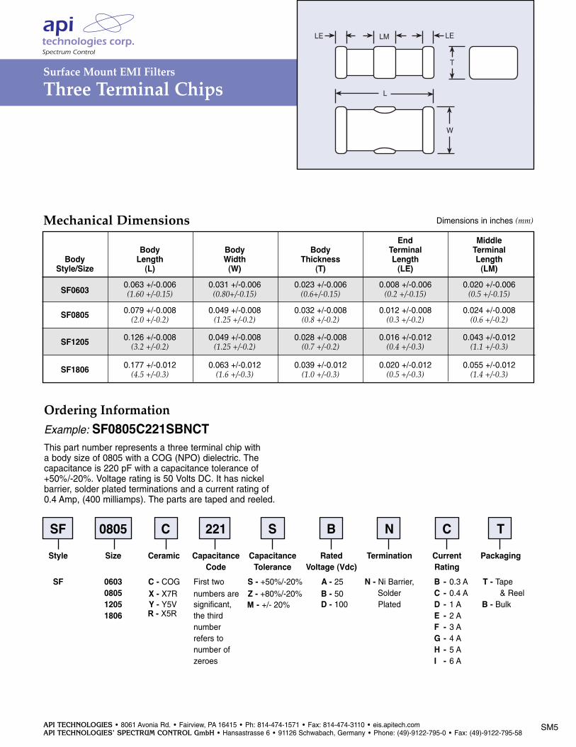
Mechanical Dimensions Dimensions in inches (mm)
Ordering InformationExample: SF0805C221SBNCTThis part number represents a three terminal chip with a body size of 0805 with a COG (NPO) dielectric. The capacitance is 220 pF with a capacitance tolerance of +50%/-20%. Voltage rating is 50 Volts DC. It has nickel barrier, solder plated terminations and a current rating of 0.4 Amp, (400 milliamps). The parts are taped and reeled.
SF 0805 C 221 S B N C TStyle Size Ceramic Capacitance Capacitance Rated Termination Current Packaging
Code Tolerance Voltage (Vdc) RatingSF 0603 C - COG First two S - +50%/-20% A - 25 N - Ni Barrier, B - 0.3 A T - Tape
0805 X - X7R numbers are Z - +80%/-20% B - 50 Solder C - 0.4 A & Reel1205 Y - Y5V significant, D - 100 Plated D - 1 A B - Bulk1806 the third E - 2 A
number F - 3 Arefers to G - 4 Anumber of H - 5 Azeroes I - 6 A
End MiddleBody Body Body Terminal Terminal
Body Length Width Thickness Length LengthStyle/Size (L) (W) (T) (LE) (LM)
0.063 +/-0.006 0.031 +/-0.006 0.023 +/-0.006 0.008 +/-0.006 0.020 +/-0.006SF0603 (1.60 +/-0.15) (0.80+/-0.15) (0.6+/-0.15) (0.2 +/-0.15) (0.5 +/-0.15)
SF0805 0.079 +/-0.008 0.049 +/-0.008 0.032 +/-0.008 0.012 +/-0.008 0.024 +/-0.008(2.0 +/-0.2) (1.25 +/-0.2) (0.8 +/-0.2) (0.3 +/-0.2) (0.6 +/-0.2)
SF1205 0.126 +/-0.008 0.049 +/-0.008 0.028 +/-0.008 0.016 +/-0.012 0.043 +/-0.012(3.2 +/-0.2) (1.25 +/-0.2) (0.7 +/-0.2) (0.4 +/-0.3) (1.1 +/-0.3)
SF1806 0.177 +/-0.012 0.063 +/-0.012 0.039 +/-0.012 0.020 +/-0.012 0.055 +/-0.012(4.5 +/-0.3) (1.6 +/-0.3) (1.0 +/-0.3) (0.5 +/-0.3) (1.4 +/-0.3)
R - X5R M - +/- 20%
API TECHNOLOGIES • 8061 Avonia Rd. • Fairview, PA 16415 • Ph: 814-474-1571 • Fax: 814-474-3110 • eis.apitech.comAPI TECHNOLOGIES’ SPECTRUM CONTROL GmbH • Hansastrasse 6 • 91126 Schwabach, Germany • Phone: (49)-9122-795-0 • Fax: (49)-9122-795-58
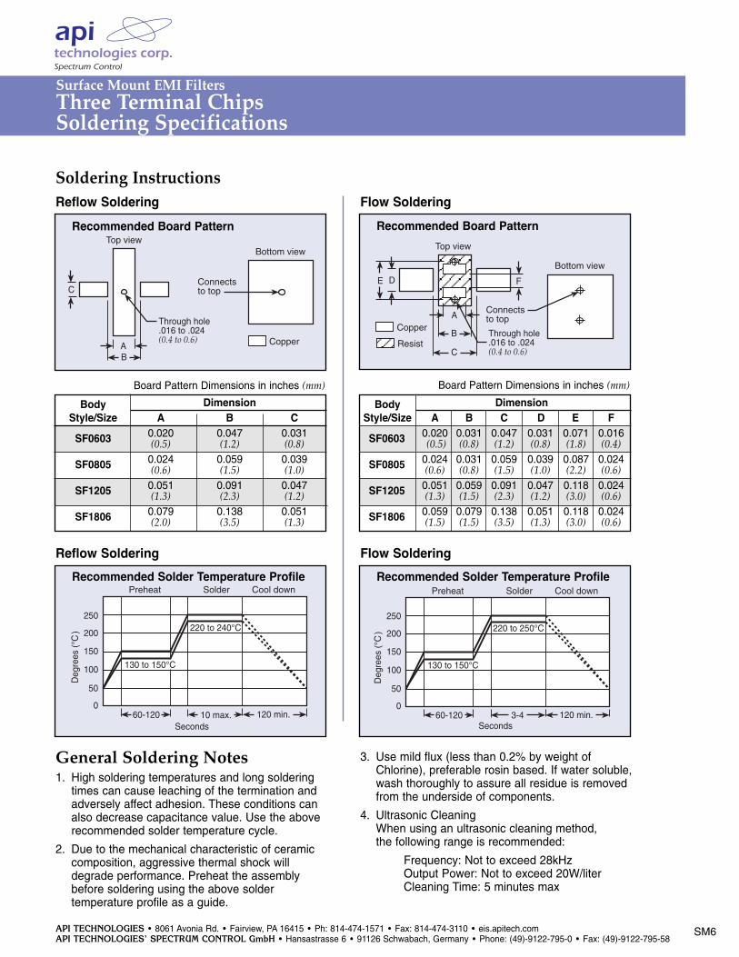
Soldering Instructions
General Soldering Notes1. High soldering temperatures and long soldering
times can cause leaching of the termination and adversely affect adhesion. These conditions can also decrease capacitance value. Use the above recommended solder temperature cycle.
2. Due to the mechanical characteristic of ceramiccomposition, aggressive thermal shock willdegrade performance. Preheat the assemblybefore soldering using the above soldertemperature profile as a guide.
3. Use mild flux (less than 0.2% by weight ofChlorine), preferable rosin based. If water soluble,wash thoroughly to assure all residue is removedfrom the underside of components.
4. Ultrasonic CleaningWhen using an ultrasonic cleaning method,the following range is recommended:
Frequency: Not to exceed 28kHzOutput Power: Not to exceed 20W/literCleaning Time: 5 minutes max
C
AB
Through hole.016 to .024(0.4 to 0.6)
Top viewBottom view
Connectsto top
Copper
Recommended Board Pattern Recommended Board PatternReflow Soldering
060-120
Preheat Solder Cool down
50
100
150
200
250
Deg
rees
(°C
)
10 max. 120 min.
130 to 150°C
220 to 240°C
Seconds
Recommended Solder Temperature Profile
Flow Soldering
Flow SolderingReflow Soldering
060-120
Preheat Solder Cool down
50
100
150
200
250
Deg
rees
(°C
)
3-4 120 min.
130 to 150°C
220 to 250°C
Seconds
Recommended Solder Temperature Profile
D
A
B Through hole.016 to .024(0.4 to 0.6)
Top view
Bottom view
Connectsto top
E
C
F
Copper
Resist
Surface Mount EMI FiltersThree Terminal ChipsSoldering Specifications
SM6
Board Pattern Dimensions in inches (mm) Board Pattern Dimensions in inches (mm)
Body DimensionStyle/Size A B C
SF0603 0.020 0.047 0.031(0.5) (1.2) (0.8)
SF0805 0.024 0.059 0.039(0.6) (1.5) (1.0)
SF1205 0.051 0.091 0.047(1.3) (2.3) (1.2)
SF1806 0.079 0.138 0.051(2.0) (3.5) (1.3)
Body DimensionStyle/Size A B C D E FSF0603 0.020 0.031 0.047 0.031 0.071 0.016
(0.5) (0.8) (1.2) (0.8) (1.8) (0.4)
SF0805 0.024 0.031 0.059 0.039 0.087 0.024(0.6) (0.8) (1.5) (1.0) (2.2) (0.6)
SF1205 0.051 0.059 0.091 0.047 0.118 0.024(1.3) (1.5) (2.3) (1.2) (3.0) (0.6)
SF1806 0.059 0.079 0.138 0.051 0.118 0.024(1.5) (1.5) (3.5) (1.3) (3.0) (0.6)
API TECHNOLOGIES • 8061 Avonia Rd. • Fairview, PA 16415 • Ph: 814-474-1571 • Fax: 814-474-3110 • eis.apitech.comAPI TECHNOLOGIES’ SPECTRUM CONTROL GmbH • Hansastrasse 6 • 91126 Schwabach, Germany • Phone: (49)-9122-795-0 • Fax: (49)-9122-795-58
SM7
D1 C C1 C2
W
B
A
E
F
T1
T
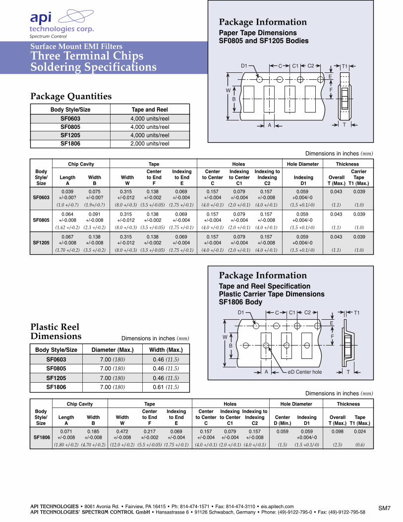
Package InformationPaper Tape DimensionsSF0805 and SF1205 Bodies
Package Quantities
Dimensions in inches (mm)
D1 C C1 C2
W
B
A øD Center hole
E
F
T1
T
Package InformationTape and Reel SpecificationPlastic Carrier Tape DimensionsSF1806 Body
Dimensions in inches (mm)
Dimensions in inches (mm)
Chip Cavity Tape Holes Hole Diameter ThicknessBody Center Indexing Center Indexing Indexing toStyle/ Length Width Width to End to End to Center to Center Indexing Center Indexing Overall TapeSize A B W F E C C1 C2 D (Min.) D1 T (Max.) T1 (Max.)
0.071 0.185 0.472 0.217 0.069 0.157 0.079 0.157 0.059 0.059 0.098 0.024SF1806 +/-0.008 +/-0.008 +/-0.008 +/-0.002 +/-0.004 +/-0.004 +/-0.004 +/-0.008 +0.004/-0
(1.80 +/-0.2) (4.70 +/-0.2) (12.0 +/-0.2) (5.5 +/-0.05) (1.75 +/-0.1) (4.0 +/-0.1) (2.0 +/-0.1) (4.0 +/-0.1) (1.5) (1.5 +0.1/-0) (2.5) (0.6)
Plastic Reel Dimensions
Surface Mount EMI FiltersThree Terminal ChipsSoldering Specifications
Body Style/Size Tape and Reel SF0603 4,000 units/reelSF0805 4,000 units/reelSF1205 4,000 units/reelSF1806 2,000 units/reel
Chip Cavity Tape Holes Hole Diameter ThicknessBody Center Indexing Center Indexing Indexing to CarrierStyle/ Length Width Width to End to End to Center to Center Indexing Indexing Overall TapeSize A B W F E C C1 C2 D1 T (Max.) T1 (Max.)
0.039 0.075 0.315 0.138 0.069 0.157 0.079 0.157 0.059 0.043 0.039SF0603 +/-0.00? +/-0.00? +/-0.012 +/-0.002 +/-0.004 +/-0.004 +/-0.004 +/-0.008 +0.004/-0
(1.0 +/-0.?) (1.9+/-0.?) (8.0 +/-0.3) (3.5 +/-0.05) (1.75 +/-0.1) (4.0 +/-0.1) (2.0 +/-0.1) (4.0 +/-0.1) (1.5 +0.1/-0) (1.1) (1.0)
0.064 0.091 0.315 0.138 0.069 0.157 0.079 0.157 0.059 0.043 0.039SF0805 +/-0.008 +/-0.008 +/-0.012 +/-0.002 +/-0.004 +/-0.004 +/-0.004 +/-0.008 +0.004/-0
(1.62 +/-0.2) (2.3 +/-0.2) (8.0 +/-0.3) (3.5 +/-0.05) (1.75 +/-0.1) (4.0 +/-0.1) (2.0 +/-0.1) (4.0 +/-0.1) (1.5 +0.1/-0) (1.1) (1.0)
0.067 0.138 0.315 0.138 0.069 0.157 0.079 0.157 0.059 0.043 0.039SF1205 +/-0.008 +/-0.008 +/-0.012 +/-0.002 +/-0.004 +/-0.004 +/-0.004 +/-0.008 +0.004/-0
(1.70 +/-0.2) (3.5 +/-0.2) (8.0 +/-0.3) (3.5 +/-0.05) (1.75 +/-0.1) (4.0 +/-0.1) (2.0 +/-0.1) (4.0 +/-0.1) (1.5 +0.1/-0) (1.1) (1.0)
Body Style/Size Diameter (Max.) Width (Max.)SF0603 7.00 (180) 0.46 (11.5)
SF0805 7.00 (180) 0.46 (11.5)
SF1205 7.00 (180) 0.46 (11.5)
SF1806 7.00 (180) 0.61 (11.5)
API TECHNOLOGIES • 8061 Avonia Rd. • Fairview, PA 16415 • Ph: 814-474-1571 • Fax: 814-474-3110 • eis.apitech.comAPI TECHNOLOGIES’ SPECTRUM CONTROL GmbH • Hansastrasse 6 • 91126 Schwabach, Germany • Phone: (49)-9122-795-0 • Fax: (49)-9122-795-58
SM8
Surface Mount Filter Arrays
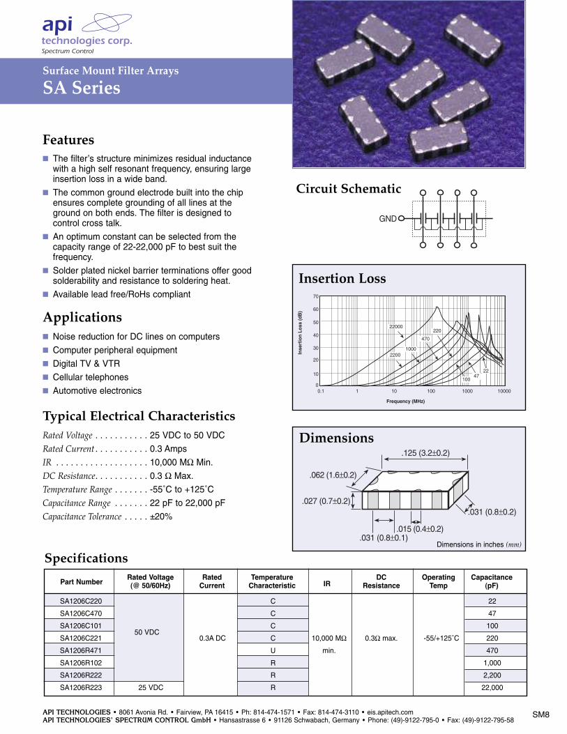
SA Series
Part Number Rated Voltage Rated TemperatureIR
DC Operating Capacitance(@ 50/60Hz) Current Characteristic Resistance Temp (pF)
C
C
C
C
U
R
R
R
Features The filter’s structure minimizes residual inductance with a high self resonant frequency, ensuring large insertion loss in a wide band.
The common ground electrode built into the chipensures complete grounding of all lines at the ground on both ends. The filter is designed to control cross talk.
An optimum constant can be selected from the capacity range of 22-22,000 pF to best suit the frequency.
Solder plated nickel barrier terminations offer good solderability and resistance to soldering heat.
Available lead free/RoHs compliant
Applications Noise reduction for DC lines on computers Computer peripheral equipment Digital TV & VTR Cellular telephones Automotive electronics
Typical Electrical CharacteristicsRated Voltage . . . . . . . . . . . 25 VDC to 50 VDCRated Current . . . . . . . . . . . 0.3 AmpsIR . . . . . . . . . . . . . . . . . . . 10,000 MΩ Min.DC Resistance. . . . . . . . . . . 0.3 Ω Max. Temperature Range . . . . . . . -55˚C to +125˚CCapacitance Range . . . . . . . 22 pF to 22,000 pFCapacitance Tolerance . . . . . ±20%
Length (L) Max.
PO.031 (0.8)Top side
chip
GND
Copper foil pattern
.011 (0.3)
GND
.086
(2.2
)
.015
(0.4
)
.039
(1.0
)
.023 (0.6)
.102 (2.6)
GND
Copper foil pattern
GND
chip
Bottom side
Ground patternGround pattern
Through hole Through hole
Top side
Bottom side
.015 (0.4±0.2)
.125 (3.2±0.2)
.062 (1.6±0.2)
.031 (0.8±0.1)
.031 (0.8±0.2)
Dimensions
GND GND
Equivalent Circuit
.027 (0.7±0.2)
PO.031 (0.8).011 (0.3)
.086
(2.2
)
.015
(0.4
)
.039
(1.0
)
.023 (0.6)
.102 (2.6)
Insertion Loss
60
50
40
30
20
0.1 1 10 100 1000 10000
Frequency (MHz)
Inse
rtio
n Lo
ss (d
B)
70
10
0
22000
22001000
470
2247
100
220
Length (L) Max.
PO.031 (0.8)Top side
chip
GND
Copper foil pattern
.011 (0.3)
GND
.086
(2.2
)
.015
(0.4
)
.039
(1.0
)
.023 (0.6)
.102 (2.6)
GND
Copper foil pattern
GND
chip
Bottom side
Ground patternGround pattern
Through hole Through hole
Top side
Bottom side
.015 (0.4±0.2)
.125 (3.2±0.2)
.062 (1.6±0.2)
.031 (0.8±0.1)
.031 (0.8±0.2)
Dimensions
GND GND
Equivalent Circuit
.027 (0.7±0.2)
PO.031 (0.8).011 (0.3)
.086
(2.2
)
.015
(0.4
)
.039
(1.0
)
.023 (0.6)
.102 (2.6)
Circuit Schematic
Dimensions
Dimensions in inches (mm)
Specifications
Insertion Loss
50 VDC
SA1206C220 22
SA1206C470 47
SA1206C101 100
SA1206C221 0.3A DC 10,000 MΩ 0.3Ω max. -55/+125˚C 220
SA1206R471 min. 470
SA1206R102 1,000
SA1206R222 2,200
SA1206R223 25 VDC 22,000
API TECHNOLOGIES • 8061 Avonia Rd. • Fairview, PA 16415 • Ph: 814-474-1571 • Fax: 814-474-3110 • eis.apitech.comAPI TECHNOLOGIES’ SPECTRUM CONTROL GmbH • Hansastrasse 6 • 91126 Schwabach, Germany • Phone: (49)-9122-795-0 • Fax: (49)-9122-795-58
SM9
Surface Mount Filter Arrays
SA Series
Length (L) Max.
PO.031 (0.8)Top side
chip
GND
Copper foil pattern
.011 (0.3)
GND
.086
(2.2
)
.015
(0.4
)
.039
(1.0
)
.023 (0.6)
.102 (2.6)
GND
Copper foil pattern
GND
chip
Bottom side
Ground patternGround pattern
Through hole Through hole
Top side
Bottom side
.015 (0.4±0.2)
.125 (3.2±0.2)
.062 (1.6±0.2)
.031 (0.8±0.1)
.031 (0.8±0.2)
Dimensions
GND GND
Equivalent Circuit
.027 (0.7±0.2)
PO.031 (0.8).011 (0.3)
.086
(2.2
)
.015
(0.4
)
.039
(1.0
)
.023 (0.6)
.102 (2.6)
Recommended Board Pattern
Dimensions in inches (mm)
Chip
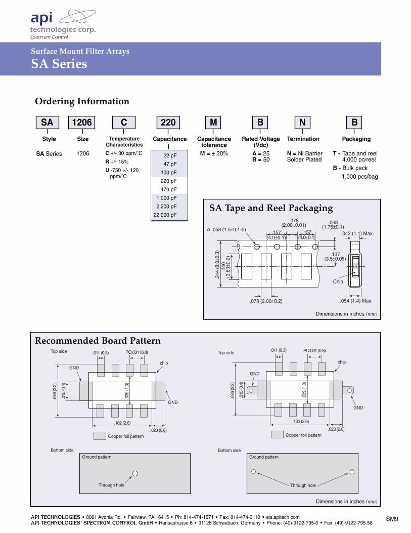
.078 (2.00±0.2)
.157(4.0±0.1)
.078(2.00±0.01)
ø .058 (1.5±0.1-0)
.314
(8.0
±0.3
).1
40(3
.60±
0.2)
.137(3.5±0.05)
.068(1.75±0.1)
.042 (1.1) Max.
.054 (1.4) Max.
.157(4.0±0.1)
SA Tape and Reel Packaging
Dimensions in inches (mm)
Ordering Information
TemperatureCharacteristicsC +/- 30 ppm/˚C
R +/- 15%
U -750 +/- 120 ppm/˚C
Style
SA Series
CapacitanceSize
1206
Capacitance toleranceM = ± 20%
Packaging
T - Tape and reel4,000 pc/reel
B - Bulk pack1,000 pcs/bag
22 pF
47 pF
100 pF
220 pF
470 pF
1,000 pF
2,200 pF
22,000 pF
Termination
N = Ni BarrierSolder Plated
Rated Voltage(Vdc)A = 25B = 50
SA 1206 C 220 M B N B
API TECHNOLOGIES • 8061 Avonia Rd. • Fairview, PA 16415 • Ph: 814-474-1571 • Fax: 814-474-3110 • eis.apitech.comAPI TECHNOLOGIES’ SPECTRUM CONTROL GmbH • Hansastrasse 6 • 91126 Schwabach, Germany • Phone: (49)-9122-795-0 • Fax: (49)-9122-795-58
PMS 279 neg. Black neg.
Surface Mount Low Pass Filters
MSM, SSM, RSM & PSM Series
SSM - Square Surface Mount Filters
RSM - Round Surface Mount Filters
PSM - Power Surface Mount Filters
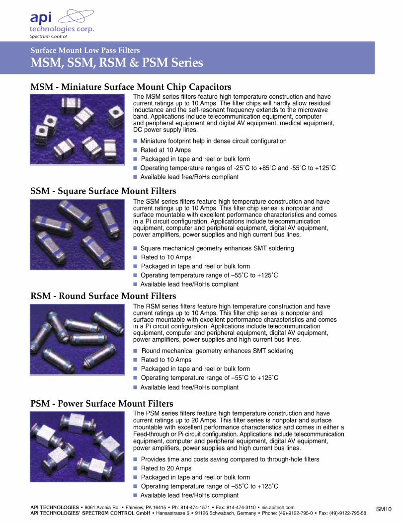
MSM - Miniature Surface Mount Chip CapacitorsThe MSM series filters feature high temperature construction and have current ratings up to 10 Amps. The filter chips will hardly allow residualinductance and the self-resonant frequency extends to the microwave band. Applications include telecommunication equipment, computer and peripheral equipment and digital AV equipment, medical equipment, DC power supply lines.
Miniature footprint help in dense circuit configuration Rated at 10 Amps Packaged in tape and reel or bulk form Operating temperature ranges of -25˚C to +85˚C and -55˚C to +125˚C Available lead free/RoHs compliant
The SSM series filters feature high temperature construction and have current ratings up to 10 Amps. This filter chip series is nonpolar and surface mountable with excellent performance characteristics and comes in a Pi circuit configuration. Applications include telecommunication equipment, computer and peripheral equipment, digital AV equipment,power amplifiers, power supplies and high current bus lines.
Square mechanical geometry enhances SMT soldering Rated to 10 Amps Packaged in tape and reel or bulk form Operating temperature range of –55˚C to +125˚C Available lead free/RoHs compliant
The RSM series filters feature high temperature construction and have current ratings up to 10 Amps. This filter chip series is nonpolar and surface mountable with excellent performance characteristics and comes in a Pi circuit configuration. Applications include telecommunication equipment, computer and peripheral equipment, digital AV equipment,power amplifiers, power supplies and high current bus lines.
Round mechanical geometry enhances SMT soldering Rated to 10 Amps Packaged in tape and reel or bulk form Operating temperature range of –55˚C to +125˚C Available lead free/RoHs compliant
The PSM series filters feature high temperature construction and have current ratings up to 20 Amps. This filter series is nonpolar and surfacemountable with excellent performance characteristics and comes in either aFeed-through or Pi circuit configuration. Applications include telecommunicationequipment, computer and peripheral equipment, digital AV equipment,power amplifiers, power supplies and high current bus lines.
Provides time and costs saving compared to through-hole filters Rated to 20 Amps Packaged in tape and reel or bulk form Operating temperature range of –55˚C to +125˚C Available lead free/RoHs compliant
SM10
API TECHNOLOGIES • 8061 Avonia Rd. • Fairview, PA 16415 • Ph: 814-474-1571 • Fax: 814-474-3110 • eis.apitech.comAPI TECHNOLOGIES’ SPECTRUM CONTROL GmbH • Hansastrasse 6 • 91126 Schwabach, Germany • Phone: (49)-9122-795-0 • Fax: (49)-9122-795-58
SM11
Surface Mount Low Pass Filters
MSM Series
.049(1.25±0.2)
.078 (2.0±0.2) .049(1.25±0.2)
.007(0.2±0.1)
.007(0.2±0.1)
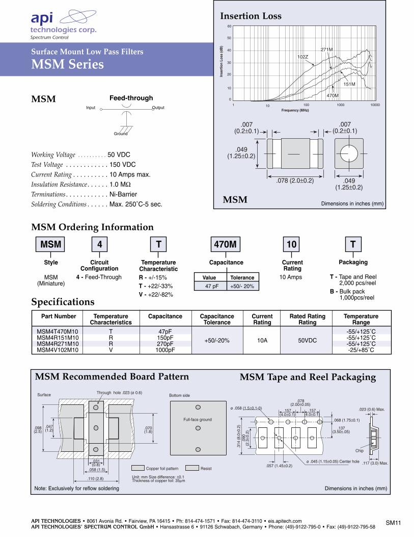
Working Voltage . . . . . . . . . . 50 VDCTest Voltage . . . . . . . . . . . . 150 VDCCurrent Rating . . . . . . . . . . 10 Amps max.Insulation Resistance. . . . . . 1.0 MΩ Terminations . . . . . . . . . . . . Ni-BarrierSoldering Conditions . . . . . . Max. 250˚C-5 sec.
MSMOutputInput
Ground
Feed-through
MSM Ordering Information
Length (L) Max.
Top side
chip
GND
Copper foil pattern
0.3
GND
2.2 0.4
1.0
0.62.6
PO.8
GND
Copper foil pattern
0.3
GND
2.2 0.4
1.0
0.62.6
chip
Bottom side
Ground patternGround pattern
Through hole Through hole
Top side
Bottom side
Full-face ground
Bottom sideSurface
.098(2.5)
Through hole .023 (ø 0.6)
.047(1.2)
.031(0.8)
.058 (1.5)
.110 (2.8)
.070(1.8)
Copper foil pattern Resist
Unit: mm Size difference: ±0.1Thickness of copper foil: 35µm
Chip
ø .045 (1.15±0.05) Center hole.057 (1.45±0.2)
.157(4.0±0.1)
.078(2.00±0.05)
ø .058 (1.5±0.1-0)
.314
(8.0
±0.2
).0
90(2
.3±0
.2) .137
(3.50±.05)
.068 (1.75±0.1)
.023 (0.6) Max.
.117 (3.0) Max.
.157(4.0±0.1)
Dimensions in inches (mm)
.049(1.25±0.2)
.078 (2.0±0.2) .049(1.25±0.2)
.007(0.2±0.1)
.007(0.2±0.1)
Dimensions in inches (mm)MSM
50
40
20
30
10
0
1 10000
Frequency (MHz)
Inse
rtio
n Lo
ss (d
B)
10 100 1000
60
102Z
151M
470M
271M
MSM Recommended Board Pattern MSM Tape and Reel Packaging
Length (L) Max.
Top side
chip
GND
Copper foil pattern
0.3
GND
2.2 0.4
1.0
0.62.6
PO.8
GND
Copper foil pattern
0.3
GND
2.2 0.4
1.0
0.62.6
chip
Bottom side
Ground patternGround pattern
Through hole Through hole
Top side
Bottom side
Full-face ground
Bottom sideSurface
.098(2.5)
Through hole .023 (ø 0.6)
.047(1.2)
.031(0.8)
.058 (1.5)
.110 (2.8)
.070(1.8)
Copper foil pattern Resist
Unit: mm Size difference: ±0.1Thickness of copper foil: 35µm
Chip
ø .045 (1.15±0.05) Center hole.057 (1.45±0.2)
.157(4.0±0.1)
.078(2.00±0.05)
ø .058 (1.5±0.1-0)
.314
(8.0
±0.2
).0
90(2
.3±0
.2) .137
(3.50±.05)
.068 (1.75±0.1)
.023 (0.6) Max.
.117 (3.0) Max.
.157(4.0±0.1)
Note: Exclusively for reflow soldering
SpecificationsPart Number Temperature Capacitance Capacitance Current Rated Rating Temperature
Characteristics Tolerance Rating Rating RangeMSM4T470M10 T 47pF -55/+125˚CMSM4R151M10 R 150pF +50/-20% 10A 50VDC -55/+125˚CMSM4R271M10 R 270pF -55/+125˚CMSM4V102M10 V 1000pF -25/+85˚C
Insertion Loss
MSM 4 T 470M 10 TStyle
MSM(Miniature)
CapacitanceCircuitConfiguration
4 - Feed-Through
CurrentRating
10 AmpsValue47 pF
Tolerance+50/- 20%
Packaging
T - Tape and Reel 2,000 pcs/reel
B - Bulk pack1,000pcs/reel
TemperatureCharacteristicR - +/-15%T - +22/-33%V - +22/-82%
API TECHNOLOGIES • 8061 Avonia Rd. • Fairview, PA 16415 • Ph: 814-474-1571 • Fax: 814-474-3110 • eis.apitech.comAPI TECHNOLOGIES’ SPECTRUM CONTROL GmbH • Hansastrasse 6 • 91126 Schwabach, Germany • Phone: (49)-9122-795-0 • Fax: (49)-9122-795-58
PMS 279 neg. Black neg.
Surface Mount Low Pass Filters
SSM & RSM Series
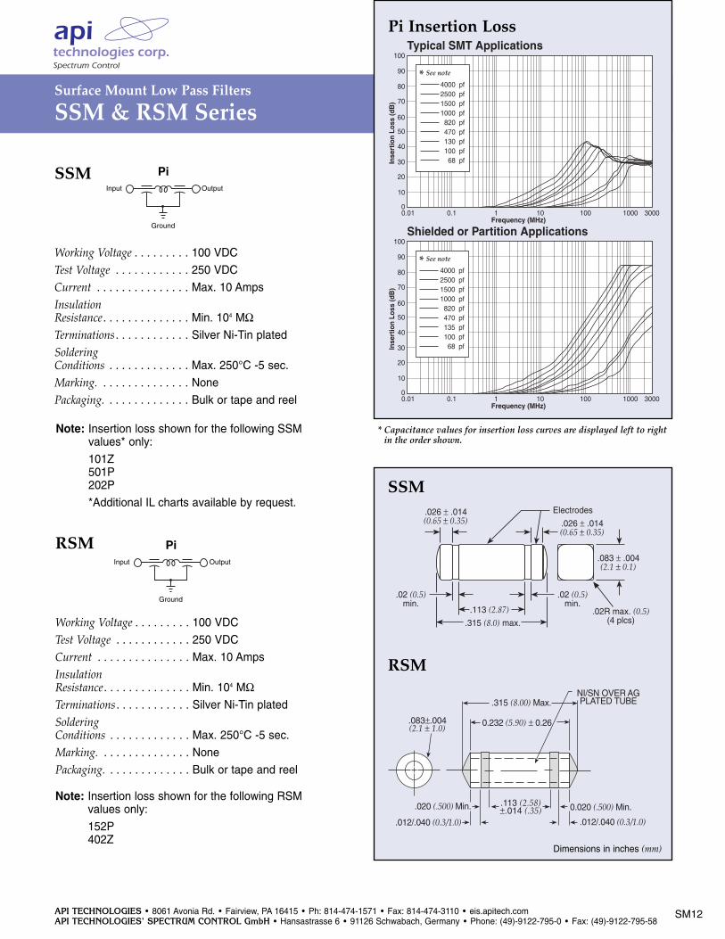
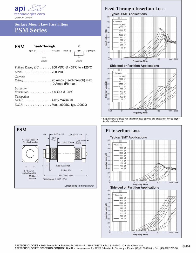
Pi Insertion Loss
3000
Typical SMT Applications
80
70
60
50
40
30
20
10
00.01 0.1 1 10 100 1000
Frequency (MHz)
Inse
rtio
n Lo
ss (d
B)
90
100
* See note
4000 pf2500 pf1500 pf1000 pf
820 pf470 pf130 pf100 pf
68 pf
3000
Shielded or Partition Applications
80
70
60
50
40
30
20
10
00.01 0.1 1 10 100 1000
Frequency (MHz)
Inse
rtio
n Lo
ss (d
B)
90
100
* See note
4000 pf2500 pf1500 pf1000 pf
820 pf470 pf135 pf100 pf
68 pf
Note: Insertion loss shown for the following SSM values* only:
101Z501P202P
*Additional IL charts available by request.
OutputInput
Ground
Pi
Working Voltage . . . . . . . . . 100 VDCTest Voltage . . . . . . . . . . . . 250 VDCCurrent . . . . . . . . . . . . . . . Max. 10 AmpsInsulationResistance. . . . . . . . . . . . . . Min. 104 MΩTerminations . . . . . . . . . . . . Silver Ni-Tin platedSolderingConditions . . . . . . . . . . . . . Max. 250°C -5 sec.Marking. . . . . . . . . . . . . . . NonePackaging. . . . . . . . . . . . . . Bulk or tape and reel
SSM
* Capacitance values for insertion loss curves are displayed left to rightin the order shown.
Note: Insertion loss shown for the following RSM values only:
152P402Z
Working Voltage . . . . . . . . . 100 VDCTest Voltage . . . . . . . . . . . . 250 VDCCurrent . . . . . . . . . . . . . . . Max. 10 AmpsInsulationResistance. . . . . . . . . . . . . . Min. 104 MΩTerminations . . . . . . . . . . . . Silver Ni-Tin platedSolderingConditions . . . . . . . . . . . . . Max. 250°C -5 sec.Marking. . . . . . . . . . . . . . . NonePackaging. . . . . . . . . . . . . . Bulk or tape and reel
RSM
.026 ± .014(0.65 ± 0.35)
Electrodes
.083 ± .004(2.1 ± 0.1)
.02 (0.5)min.
.113 (2.87).315 (8.0) max.
.026 ± .014(0.65 ± 0.35)
.02 (0.5)min.
.02R max. (0.5)(4 plcs)
SSM
0.232 (5.90) ± 0.26
.020 (.500) Min.
.012/.040 (0.3/1.0)
.113 (2.58)±.014 (.35) 0.020 (.500) Min.
.012/.040 (0.3/1.0)
.083±.004(2.1 ± 1.0)
.315 (8.00) Max.NI/SN OVER AGPLATED TUBE
Dimensions in inches (mm)
RSM
OutputInput
Ground
Pi
SM12
Dimensions in inches (mm)
API TECHNOLOGIES • 8061 Avonia Rd. • Fairview, PA 16415 • Ph: 814-474-1571 • Fax: 814-474-3110 • eis.apitech.comAPI TECHNOLOGIES’ SPECTRUM CONTROL GmbH • Hansastrasse 6 • 91126 Schwabach, Germany • Phone: (49)-9122-795-0 • Fax: (49)-9122-795-58
SM13
Surface Mount Low Pass Filters
SSM & RSM Series
.630(16.0)
.069(1.75)
.295(7.50)
.157(4.00)
.079(2.00)
.059(1.50)
.315(8.00)
.098(2.50)
.013(0.33)
.157(4.00)
.059(1.50)
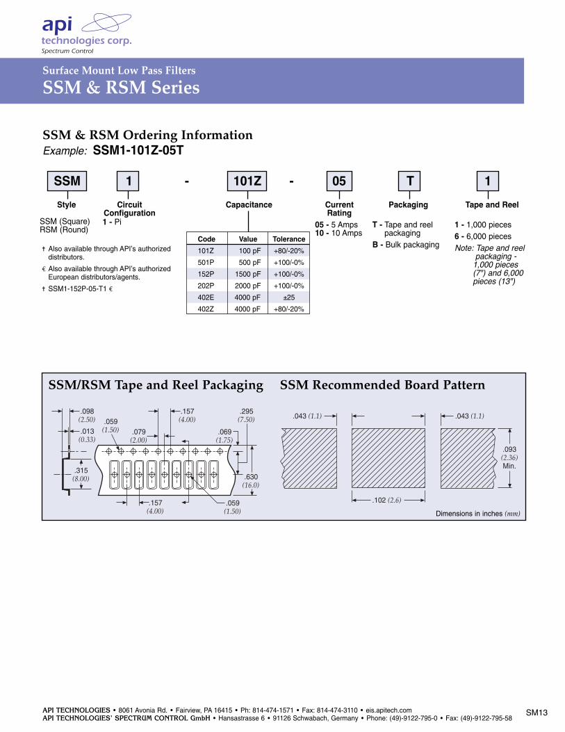
SSM 1 - 101Z - 05 T 1Style
SSM (Square)RSM (Round)
CapacitanceCircuitConfiguration1 - Pi
CurrentRating
05 - 5 Amps 10 - 10 Amps
Packaging
T - Tape and reelpackaging
B - Bulk packagingCode101Z
501P
152P
202P
402E
402Z
Value100 pF
500 pF
1500 pF
2000 pF
4000 pF
4000 pF
Tolerance+80/-20%
+100/-0%
+100/-0%
+100/-0%
±25
+80/-20%
SSM & RSM Ordering InformationExample: SSM1-101Z-05T
Tape and Reel
1 - 1,000 pieces6 - 6,000 piecesNote: Tape and reel
packaging - 1,000 pieces (7") and 6,000 pieces (13")
Also available through API’s authorized distributors.
€ Also available through API’s authorized European distributors/agents.
SSM1-152P-05-T1 €
SSM/RSM Tape and Reel Packaging
.102 (2.6)
.093(2.36)Min.
.043 (1.1) .043 (1.1)
SSM Recommended Board Pattern
Dimensions in inches (mm)
API TECHNOLOGIES • 8061 Avonia Rd. • Fairview, PA 16415 • Ph: 814-474-1571 • Fax: 814-474-3110 • eis.apitech.comAPI TECHNOLOGIES’ SPECTRUM CONTROL GmbH • Hansastrasse 6 • 91126 Schwabach, Germany • Phone: (49)-9122-795-0 • Fax: (49)-9122-795-58
Surface Mount Low Pass Filters
PSM Series
.120 (3.00)Sq. (both ends)
.025 (0.63) Ref.
.070 (1.75)(4x both ends)
Middleterminal
.026 (0.66)
.057(1.46)
.120 (3.00)
.026 (0.66)
.010(0.25)
.315 (8.00) Max.
.235 (6.00)
Tolerances: ± .010 (.254)
Dimensions in inches (mm)
Feed-Through Insertion LossTypical SMT Applications
80
70
60
50
40
30
20
10
00.01 0.1 1 10 100 1000
Frequency (MHz)
Inse
rtio
n Lo
ss (d
B)
3000
* See note
0.01 uF4000 pf2500 pf1500 pf1000 pf
820 pf470 pf130 pf100 pf
68 pf
Shielded or Partition Applications80
70
60
50
40
30
20
10
00.01 0.1 1 10 100 1000
Frequency (MHz)
Inse
rtio
n Lo
ss (d
B)
3000
* See note
0.01 uF4000 pf2500 pf1500 pf1000 pf
820 pf470 pf130 pf100 pf
68 pf
Voltage Rating DC . . . . . . . 200 VDC @ -55°C to +125°C
DWV . . . . . . . . . . . . . . . . . 700 VDCCurrentRating . . . . . . . . . . . . . . . . 20 Amps (Feed-through) max.. . . . . . . . . . . . . . . . . . 10 Amps (Pi) max.
InsulationResistance. . . . . . . . . . . . . . 1.0 GΩ @ 25°C
DissipationFactor. . . . . . . . . . . . . . . . . 4.0% maximumD.C.R. . . . . . . . . . . . . . . . . Max. .0005Ω, typ. .0002Ω
PSMOutputInput
Ground
OutputInput
Ground
PiFeed-Through
* Capacitance values for insertion loss curves are displayed left to rightin the order shown.
Pi Insertion Loss
3000
Typical SMT Applications
80
70
60
50
40
30
20
10
00.01 0.1 1 10 100 1000
Frequency (MHz)
Inse
rtio
n Lo
ss (d
B)
90
100
* See note
4000 pf2500 pf1500 pf1000 pf
820 pf470 pf130 pf100 pf
68 pf
3000
Shielded or Partition Applications
80
70
60
50
40
30
20
10
00.01 0.1 1 10 100 1000
Frequency (MHz)
Inse
rtio
n Lo
ss (d
B)
90
100
* See note
4000 pf2500 pf1500 pf1000 pf
820 pf470 pf135 pf100 pf
68 pf
PSM
SM14
API TECHNOLOGIES • 8061 Avonia Rd. • Fairview, PA 16415 • Ph: 814-474-1571 • Fax: 814-474-3110 • eis.apitech.comAPI TECHNOLOGIES’ SPECTRUM CONTROL GmbH • Hansastrasse 6 • 91126 Schwabach, Germany • Phone: (49)-9122-795-0 • Fax: (49)-9122-795-58
Surface Mount Low Pass Filters
PSM Series
.630(16.0)
.069(1.75)
.295(7.50)
.157(4.00)
.079(2.00)
.059(1.50)
.320(8.13)
.150(3.81)
.013(0.33)
.315(8.00) .133
(3.38)
.059(1.50)
.040(1.00) min.
Solder paste pattern
Recommended pad,must be able to supportcontinuous signal current
X = 0.350" minimum for 1 oz. copper(0.036 mm thickness)
X = 0.200" minimum for 2 oz. copper(0.071 mm thickness)
For low current (10 Amp or less)X = 0.130" minimum for 1 oz. copper
(0.036 mm thickness for 10 Ampand 0.5 oz. copper - 0.018 mmthickness for 5 Amp or less)
Dimensions in inches (mm)
X
.285 (7.25)
.050(1.27)
.100 (2.54)
.125 (3.20)
.070 (1.75) 0.10(2.54)
.065(1.65)
120°
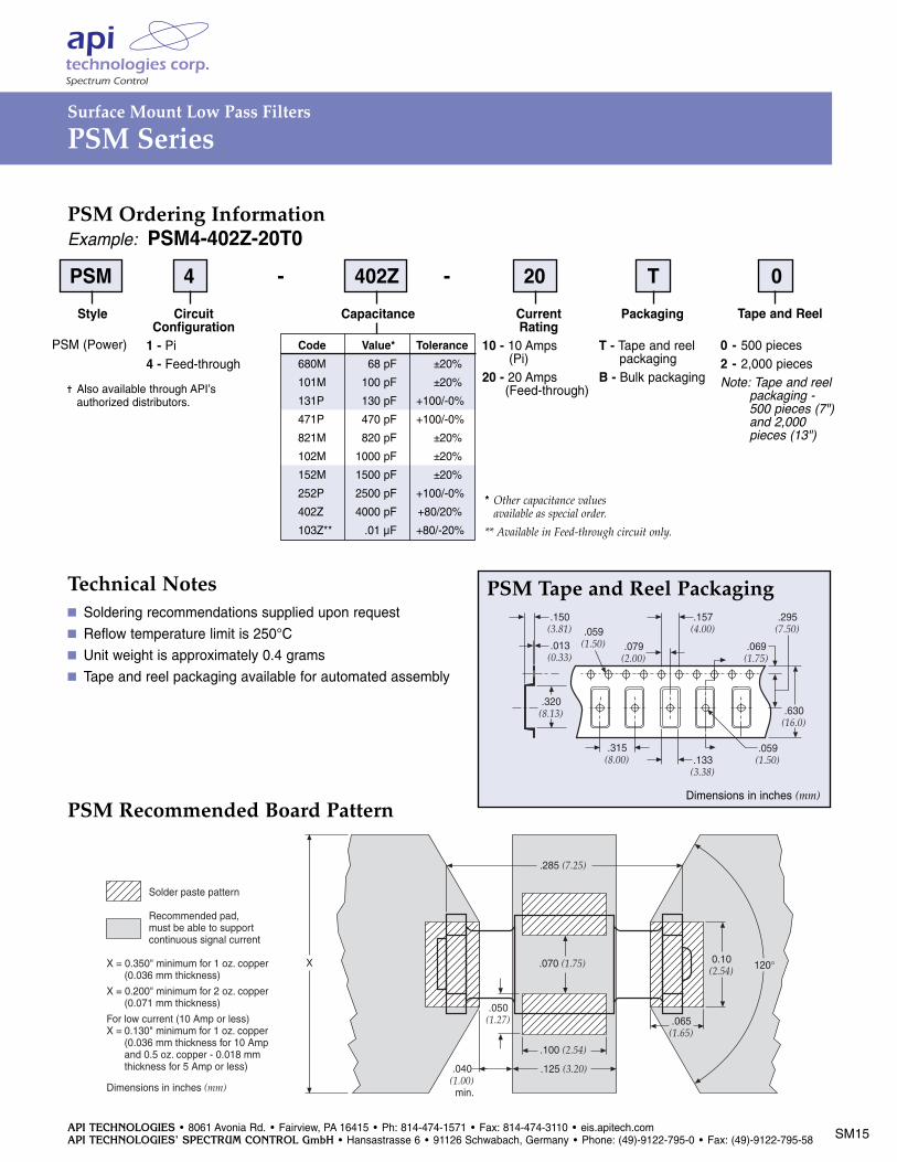
Technical Notes Soldering recommendations supplied upon request Reflow temperature limit is 250°C Unit weight is approximately 0.4 grams Tape and reel packaging available for automated assembly
PSM Tape and Reel Packaging
Dimensions in inches (mm)
Code680M
101M
131P
471P
821M
102M
152M
252P
402Z
103Z**
PSM Ordering InformationExample: PSM4-402Z-20T0PSM 4 - 402Z - 20 T 0
Style
PSM (Power)
CapacitanceCircuitConfiguration
1 - Pi4 - Feed-through
Current Rating
10 - 10 Amps (Pi)
20 - 20 Amps (Feed-through)
* Other capacitance values available as special order.
** Available in Feed-through circuit only.
Packaging
T - Tape and reelpackaging
B - Bulk packaging
Value*68 pF
100 pF
130 pF
470 pF
820 pF
1000 pF
1500 pF
2500 pF
4000 pF
.01 µF
Tolerance±20%
±20%
+100/-0%
+100/-0%
±20%
±20%
±20%
+100/-0%
+80/20%
+80/-20%
Tape and Reel
0 - 500 pieces2 - 2,000 piecesNote: Tape and reel
packaging - 500 pieces (7") and 2,000 pieces (13")
Also available through API’s authorized distributors.
PSM Recommended Board Pattern
SM15
API TECHNOLOGIES • 8061 Avonia Rd. • Fairview, PA 16415 • Ph: 814-474-1571 • Fax: 814-474-3110 • eis.apitech.comAPI TECHNOLOGIES’ SPECTRUM CONTROL GmbH • Hansastrasse 6 • 91126 Schwabach, Germany • Phone: (49)-9122-795-0 • Fax: (49)-9122-795-58
SM16
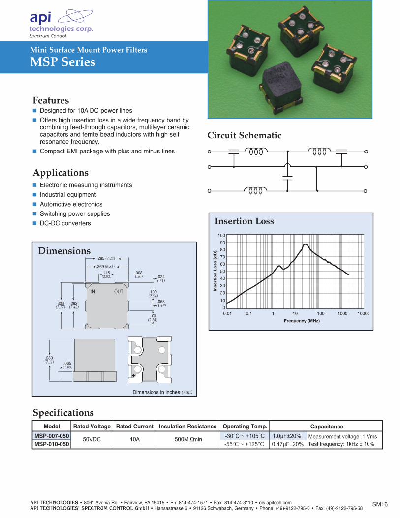
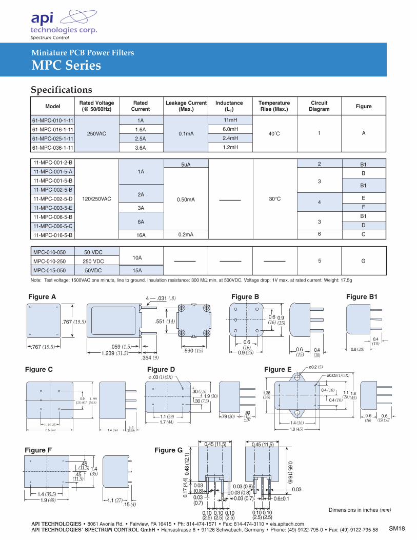
Model Rated Voltage Rated Current Insulation Resistance Operating Temp.
MSP-007-050 50VDC 10A 500M Ω -30°C ~ +105°C MSP-010-050 -55°C ~ +125°C
90
80
70
60
50
0.01 0.1 1 10 100 1000
Frequency (MHz)
Inse
rtio
n L
oss
(d
B)
100
30
20
10
0
40
10000
IN OUT
.065(1.65)
.280(7.11)
.306(7.77)
.292(7.42)
.100(2.54)
.100(2.54)
.024(.61)
.058(1.47)
.285 (7.24)
.269 (6.83).115(2.92)
.008(.20)
++
Features
Circuit Schematic
Designed for 10A DC power lines Offers high insertion loss in a wide frequency band by
combining feed-through capacitors, multilayer ceramic capacitors and ferrite bead inductors with high self resonance frequency.
Compact EMI package with plus and minus lines
Applications
Dimensions
Insertion Loss
Specifications
Electronic measuring instruments Industrial equipment Automotive electronics
Switching power supplies
DC-DC converters
Dimensions in inches (mm)
Mini Surface Mount Power Filters
MSP Series
min.
Capacitance1.0µF±20%0.47µF±20%
Measurement voltage: 1 VmsTest frequency: 1kHz ± 10%
API TECHNOLOGIES • 8061 Avonia Rd. • Fairview, PA 16415 • Ph: 814-474-1571 • Fax: 814-474-3110 • eis.apitech.comAPI TECHNOLOGIES’ SPECTRUM CONTROL GmbH • Hansastrasse 6 • 91126 Schwabach, Germany • Phone: (49)-9122-795-0 • Fax: (49)-9122-795-58
61-MPC Series
Circuit Diagrams
Tested and found to beIAW VDE 0565 Part 3
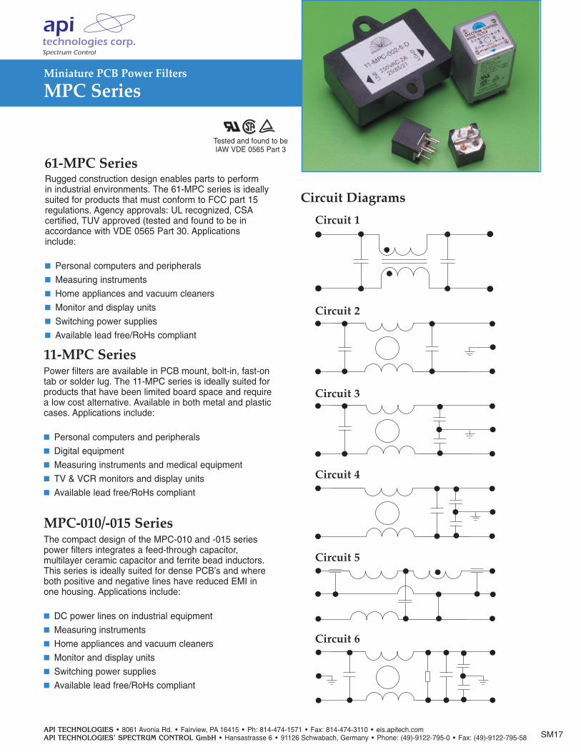
Rugged construction design enables parts to perform in industrial environments. The 61-MPC series is ideally suited for products that must conform to FCC part 15 regulations. Agency approvals: UL recognized, CSA certified, TUV approved (tested and found to be in accordance with VDE 0565 Part 30. Applicationsinclude:
Personal computers and peripherals Measuring instruments Home appliances and vacuum cleaners Monitor and display units Switching power supplies Available lead free/RoHs compliant
Power filters are available in PCB mount, bolt-in, fast-ontab or solder lug. The 11-MPC series is ideally suited forproducts that have been limited board space and requirea low cost alternative. Available in both metal and plasticcases. Applications include:
Personal computers and peripherals Digital equipment Measuring instruments and medical equipment TV & VCR monitors and display units Available lead free/RoHs compliant
11-MPC Series
The compact design of the MPC-010 and -015 seriespower filters integrates a feed-through capacitor, multilayer ceramic capacitor and ferrite bead inductors.This series is ideally suited for dense PCB’s and whereboth positive and negative lines have reduced EMI in one housing. Applications include:
DC power lines on industrial equipment Measuring instruments Home appliances and vacuum cleaners Monitor and display units Switching power supplies Available lead free/RoHs compliant
MPC-010/-015 Series
Circuit 1
Circuit 2
Circuit 3
Circuit 4
Circuit 5
SM17
Miniature PCB Power Filters
MPC Series
Circuit 6
SM18
MPC-010-050 50 VDC 10A
MPC-010-250 250 VDC
MPC-015-050 50VDC 15A
0.4(10)
0.8 (20)
1 3
2 4
.767 (19.5)1.239 (31.5)
.767 (19.5)
.059 (1.5)
.354 (9)
4 — .031 (.8)
.551 (14)
.590 (15)
11mH
6.0mH
2.4mH
1.2mH
2
3
4
3
6
B1
B
B1
E
F
B1
D
C
1A
2A
3A
6A
16A
11-MPC-001-2-B
11-MPC-001-5-A
11-MPC-001-5-B
11-MPC-002-5-B
11-MPC-002-5-D
11-MPC-003-5-E
11-MPC-006-5-B
11-MPC-006-5-C
11-MPC-016-5-B
61-MPC-010-1-11 1A
61-MPC-016-1-11 250VAC
1.6A 0.1mA 40˚C 1
A
61-MPC-025-1-11 2.5A
61-MPC-036-1-11 3.6A
30°C
0.17
(4.4
)
0.45 (11.5)
0.48
(12.
1)
0.10(2.5)
0.10(2.5)
0.10(2.5)
0.03 (0.7)0.03(0.7)
0.03 (0.8)0.03 (0.8)
0.45 (11.5)
0.10(2.5)
0.10(2.5)
0.6±0.1
0.03 (0.8)
0.65 (16.6)
0.03(0.8)
Specifications
120/250VAC
Figure C
0.6(16)
0.6(15)0.9 (25) 0.4
(10)
0.9(25)
0.6(16)
Figure A
0.6(16)
0.6(15) ±.07
1.4 (36)1.8 (45)
0.4 (10)
1.1(28)
0.4 (10)1.38(35)
1.8(45)
ø0.2 (5)
ø0.03 (1) (5X)Figure E
1.4 (35.5)
.45(11.5)
1.9 (49)
.45(11.5)
1.4(35)
1.1 (27).15 (4)
Figure F
1.9 (30)
.79 (20)1.1 (29)1.7 (44)
.30 (7.5)
.60(15)±.07
.30 (7.5)
.03 (1) (5X)Figure D
Dimensions in inches (mm)
Model
Rated Voltage Rated Leakage Current Inductance Temperature Circuit Figure (@ 50/60Hz) Current (Max.) (L1) Rise (Max.) Diagram
5uA
0.50mA
0.2mA
Figure B
Figure G
Note: Test voltage: 1500VAC one minute, line to ground. Insulation resistance: 300 MΩ min. at 500VDC. Voltage drop: 1V max. at rated current. Weight: 17.5g
5 G
Miniature PCB Power Filters
MPC Series
API TECHNOLOGIES • 8061 Avonia Rd. • Fairview, PA 16415 • Ph: 814-474-1571 • Fax: 814-474-3110 • eis.apitech.comAPI TECHNOLOGIES’ SPECTRUM CONTROL GmbH • Hansastrasse 6 • 91126 Schwabach, Germany • Phone: (49)-9122-795-0 • Fax: (49)-9122-795-58
1.99(50.8)
1.4 (36)
1.06 (27)
2.5 (64)
0.9(25).007
6.5(25.59)
Figure B1
API TECHNOLOGIES • 8061 Avonia Rd. • Fairview, PA 16415 • Ph: 814-474-1571 • Fax: 814-474-3110 • eis.apitech.comAPI TECHNOLOGIES’ SPECTRUM CONTROL GmbH • Hansastrasse 6 • 91126 Schwabach, Germany • Phone: (49)-9122-795-0 • Fax: (49)-9122-795-58
120
100
80
60
40
20
030 40 50 60 70 80 90
Ambient Temperature (°C)
Cur
rent
(%)
0 100
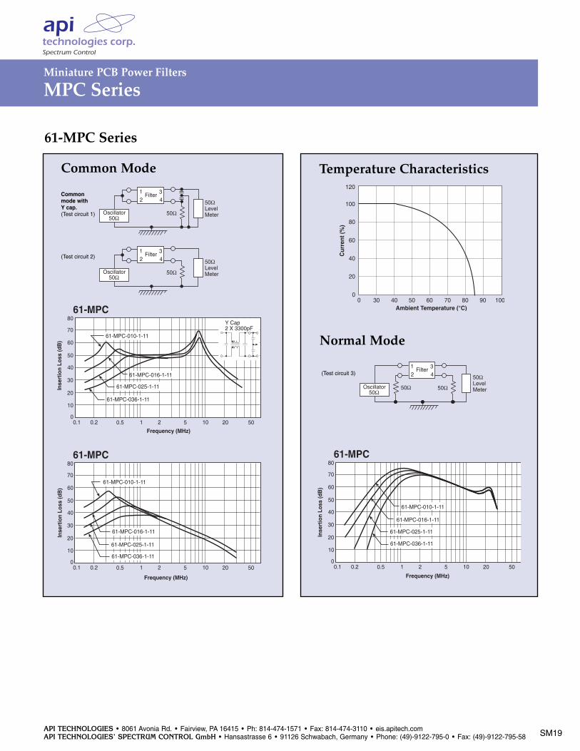
61-MPC Series
Common Mode
Normal Mode
50ΩLevelMeter50Ω
1 32 4
Filter
Oscillator50Ω
50ΩLevelMeter50Ω
1 32 4
Filter
Oscillator50Ω
61-MPC
Inse
rtio
n Lo
ss (d
B)
80
Frequency (MHz)
70
60
50
40
30
20
10
00.1 0.2 0.5 1 2 5 10 20 50
61-MPC-010-1-11
61-MPC-036-1-11
61-MPC-025-1-11
61-MPC-016-1-11
Y Cap2 X 3300pF
61-MPC
Inse
rtio
n Lo
ss (d
B)
80
Frequency (MHz)
70
60
50
40
30
20
10
00.1 0.2 0.5 1 2 5 10 20 50
61-MPC-036-1-11
61-MPC-025-1-11
61-MPC-016-1-11
61-MPC-010-1-11
61-MPC
Inse
rtio
n Lo
ss (d
B)
80
Frequency (MHz)
70
60
50
40
30
20
10
00.1 0.2 0.5 1 2 5 10 20 50
61-MPC-036-1-11
61-MPC-010-1-11
61-MPC-025-1-11
61-MPC-016-1-11
50ΩLevelMeter50Ω
1 32 4
Filter
Oscillator50Ω
50Ω
Commonmode withY cap.(Test circuit 1)
(Test circuit 2)
(Test circuit 3)
Temperature Characteristics
SM19
Miniature PCB Power Filters
MPC Series
API TECHNOLOGIES • 8061 Avonia Rd. • Fairview, PA 16415 • Ph: 814-474-1571 • Fax: 814-474-3110 • eis.apitech.comAPI TECHNOLOGIES’ SPECTRUM CONTROL GmbH • Hansastrasse 6 • 91126 Schwabach, Germany • Phone: (49)-9122-795-0 • Fax: (49)-9122-795-58 SM20
50ΩLevelMeter50Ω
1 32 4
Filter
Oscillator50Ω
Common Mode
50ΩLevelMeter50Ω
1 32 4
Filter
Oscillator50Ω
50Ω
Normal Mode
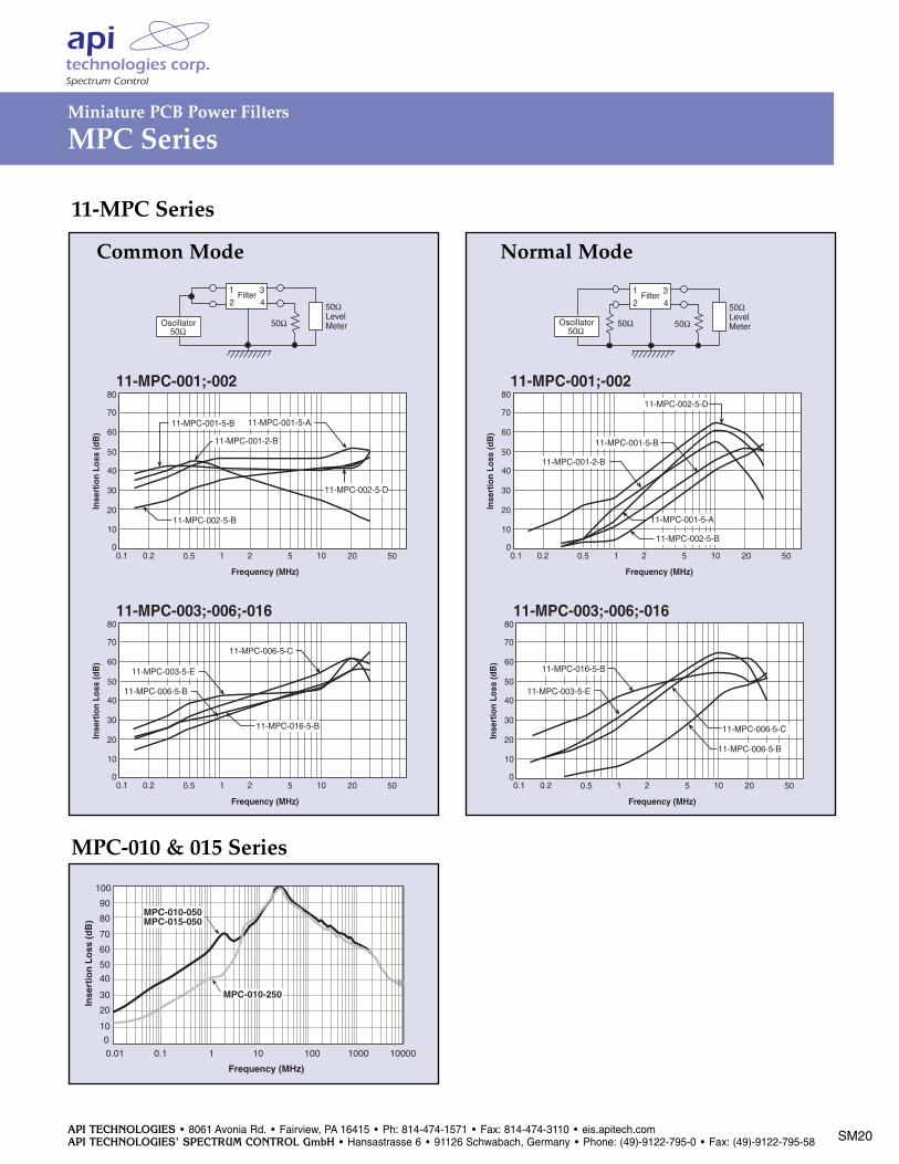
11-MPC-001;-002
Inse
rtio
n Lo
ss (d
B)
80
Frequency (MHz)
70
60
50
40
30
20
10
00.1 0.2 0.5 1 2 5 10 20 50
11-MPC-003;-006;-016
Inse
rtio
n Lo
ss (d
B)
80
Frequency (MHz)
70
60
50
40
30
20
10
00.1 0.2 0.5 1 2 5 10 20 50
11-MPC-001;-002
Inse
rtio
n Lo
ss (d
B)
80
Frequency (MHz)
70
60
50
40
30
20
10
00.1 0.2 0.5 1 2 5 10 20 50
11-MPC-001-5-A
11-MPC-003;-006;-016
Inse
rtio
n Lo
ss (d
B)
80
Frequency (MHz)
70
60
50
40
30
20
10
00.1 0.2 0.5 1 2 5 10 20 50
11-MPC-002-5-B
11-MPC-001-2-B
11-MPC-003-5-E
11-MPC-016-5-B
11-MPC-001-5-B
11-MPC-002-5-D
11-MPC-006-5-B
11-MPC-006-5-C
11-MPC-001-5-A
11-MPC-001-2-B
11-MPC-001-5-B
11-MPC-002-5-B
11-MPC-002-5-D
11-MPC-003-5-E
11-MPC-006-5-B
11-MPC-006-5-C
11-MPC-016-5-B
11-MPC-001;-002
Inse
rtio
n Lo
ss (d
B)
80
Frequency (MHz)
70
60
50
40
30
20
10
00.1 0.2 0.5 1 2 5 10 20 50
11-MPC-003;-006;-016
Inse
rtio
n Lo
ss (d
B)
80
Frequency (MHz)
70
60
50
40
30
20
10
00.1 0.2 0.5 1 2 5 10 20 50
11-MPC-001;-002
Inse
rtio
n Lo
ss (d
B)
80
Frequency (MHz)
70
60
50
40
30
20
10
00.1 0.2 0.5 1 2 5 10 20 50
11-MPC-001-5-A
11-MPC-003;-006;-016
Inse
rtio
n Lo
ss (d
B)
80
Frequency (MHz)
70
60
50
40
30
20
10
00.1 0.2 0.5 1 2 5 10 20 50
11-MPC-002-5-B
11-MPC-001-2-B
11-MPC-003-5-E
11-MPC-016-5-B
11-MPC-001-5-B
11-MPC-002-5-D
11-MPC-006-5-B
11-MPC-006-5-C
11-MPC-001-5-A
11-MPC-001-2-B
11-MPC-001-5-B
11-MPC-002-5-B
11-MPC-002-5-D
11-MPC-003-5-E
11-MPC-006-5-B
11-MPC-006-5-C
11-MPC-016-5-B
11-MPC-001;-002
Inse
rtio
n Lo
ss (d
B)
80
Frequency (MHz)
70
60
50
40
30
20
10
00.1 0.2 0.5 1 2 5 10 20 50
11-MPC-003;-006;-016
Inse
rtio
n Lo
ss (d
B)
80
Frequency (MHz)
70
60
50
40
30
20
10
00.1 0.2 0.5 1 2 5 10 20 50
11-MPC-001;-002
Inse
rtio
n Lo
ss (d
B)
80
Frequency (MHz)
70
60
50
40
30
20
10
00.1 0.2 0.5 1 2 5 10 20 50
11-MPC-001-5-A
11-MPC-003;-006;-016
Inse
rtio
n Lo
ss (d
B)
80
Frequency (MHz)
70
60
50
40
30
20
10
00.1 0.2 0.5 1 2 5 10 20 50
11-MPC-002-5-B
11-MPC-001-2-B
11-MPC-003-5-E
11-MPC-016-5-B
11-MPC-001-5-B
11-MPC-002-5-D
11-MPC-006-5-B
11-MPC-006-5-C
11-MPC-001-5-A
11-MPC-001-2-B
11-MPC-001-5-B
11-MPC-002-5-B
11-MPC-002-5-D
11-MPC-003-5-E
11-MPC-006-5-B
11-MPC-006-5-C
11-MPC-016-5-B
11-MPC-001;-002
Inse
rtio
n Lo
ss (d
B)
80
Frequency (MHz)
70
60
50
40
30
20
10
00.1 0.2 0.5 1 2 5 10 20 50
11-MPC-003;-006;-016
Inse
rtio
n Lo
ss (d
B)
80
Frequency (MHz)
70
60
50
40
30
20
10
00.1 0.2 0.5 1 2 5 10 20 50
11-MPC-001;-002
Inse
rtio
n Lo
ss (d
B)
80
Frequency (MHz)
70
60
50
40
30
20
10
00.1 0.2 0.5 1 2 5 10 20 50
11-MPC-001-5-A
11-MPC-003;-006;-016
Inse
rtio
n Lo
ss (d
B)
80
Frequency (MHz)
70
60
50
40
30
20
10
00.1 0.2 0.5 1 2 5 10 20 50
11-MPC-002-5-B
11-MPC-001-2-B
11-MPC-003-5-E
11-MPC-016-5-B
11-MPC-001-5-B
11-MPC-002-5-D
11-MPC-006-5-B
11-MPC-006-5-C
11-MPC-001-5-A
11-MPC-001-2-B
11-MPC-001-5-B
11-MPC-002-5-B
11-MPC-002-5-D
11-MPC-003-5-E
11-MPC-006-5-B
11-MPC-006-5-C
11-MPC-016-5-B
11-MPC Series
MPC-010 & 015 Series
90
80
70
60
50
0.01 0.1 1 10 100 1000
Frequency (MHz)
Inse
rtio
n L
oss
(d
B)
100
30
20
10
0
40
10000
MPC-010-250
MPC-010-050MPC-015-050
Miniature PCB Power Filters
MPC Series
API TECHNOLOGIES • 8061 Avonia Rd. • Fairview, PA 16415 • Ph: 814-474-1571 • Fax: 814-474-3110 • eis.apitech.comAPI TECHNOLOGIES’ SPECTRUM CONTROL GmbH • Hansastrasse 6 • 91126 Schwabach, Germany • Phone: (49)-9122-795-0 • Fax: (49)-9122-795-58
SM21
Through-hole Filters
High Frequency PCB Filters
PMS 279 neg. Black neg.
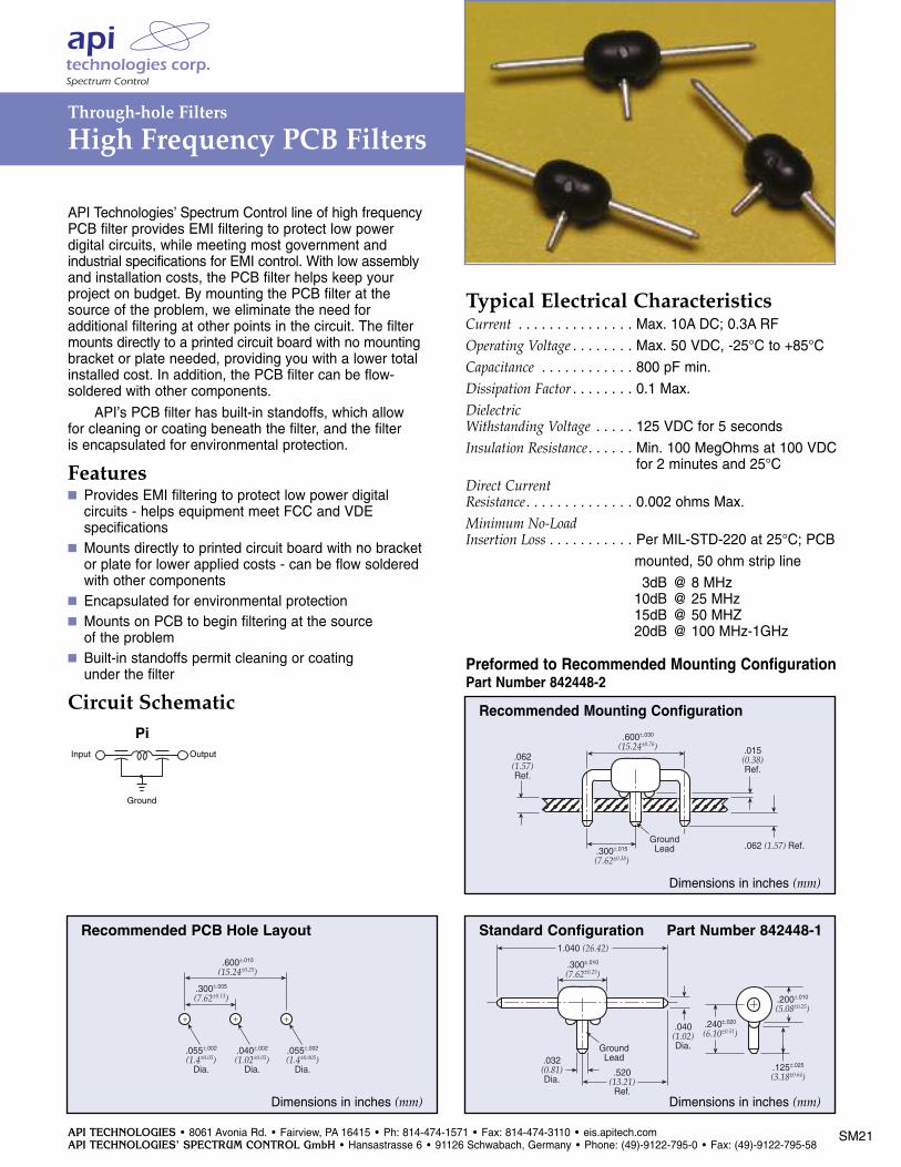
API Technologies’ Spectrum Control line of high frequencyPCB filter provides EMI filtering to protect low power digital circuits, while meeting most government andindustrial specifications for EMI control. With low assemblyand installation costs, the PCB filter helps keep your project on budget. By mounting the PCB filter at thesource of the problem, we eliminate the need for additional filtering at other points in the circuit. The filtermounts directly to a printed circuit board with no mountingbracket or plate needed, providing you with a lower totalinstalled cost. In addition, the PCB filter can be flow-soldered with other components.
API’s PCB filter has built-in standoffs, which allowfor cleaning or coating beneath the filter, and the filter is encapsulated for environmental protection.
Features Provides EMI filtering to protect low power digital circuits - helps equipment meet FCC and VDE specifications
Mounts directly to printed circuit board with no bracket or plate for lower applied costs - can be flow soldered with other components
Encapsulated for environmental protection Mounts on PCB to begin filtering at the source of the problem
Built-in standoffs permit cleaning or coating under the filter
Circuit Schematic
Typical Electrical CharacteristicsCurrent . . . . . . . . . . . . . . . Max. 10A DC; 0.3A RFOperating Voltage . . . . . . . . Max. 50 VDC, -25°C to +85°CCapacitance . . . . . . . . . . . . 800 pF min.Dissipation Factor . . . . . . . . 0.1 Max.DielectricWithstanding Voltage . . . . . 125 VDC for 5 secondsInsulation Resistance. . . . . . Min. 100 MegOhms at 100 VDC . . . . . . . . . . . . . . . . . . . . . for 2 minutes and 25°C
Direct Current Resistance. . . . . . . . . . . . . . 0.002 ohms Max. Minimum No-LoadInsertion Loss . . . . . . . . . . . Per MIL-STD-220 at 25°C; PCB
mounted, 50 ohm strip line
3dB @ 8 MHz10dB @ 25 MHz15dB @ 50 MHZ20dB @ 100 MHz-1GHz
.600±.030
(15.24±0.76)
GroundLead.300±.015
(7.62±0.38)
.015(0.38)Ref.
.062 (1.57) Ref.
.062(1.57)Ref.
+ + +
.600±.010
(15.24±0.25)
.300±.005
(7.62±0.13)
.055±.002
(1.4±0.05)Dia.
.040±.002
(1.02±0.05)Dia.
.055±.002
(1.4±0.005)Dia.
GroundLead
.300±.010
(7.62±0.25)
1.040 (26.42)
.032(0.81)Dia.
.520(13.21)
Ref.
.040(1.02)Dia.
.240±.020
(6.10±0.51)
.200±.010
(5.08±0.25)
.125±.025
(3.18±0.64)
Standard Configuration Part Number 842448-1
.600±.030
(15.24±0.76)
GroundLead.300±.015
(7.62±0.38)
.015(0.38)Ref.
.062 (1.57) Ref.
.062(1.57)Ref.
+ + +
.600±.010
(15.24±0.25)
.300±.005
(7.62±0.13)
.055±.002
(1.4±0.05)Dia.
.040±.002
(1.02±0.05)Dia.
.055±.002
(1.4±0.005)Dia.
GroundLead
.300±.010
(7.62±0.25)
1.040 (26.42)
.032(0.81)Dia.
.520(13.21)
Ref.
.040(1.02)Dia.
.240±.020
(6.10±0.51)
.200±.010
(5.08±0.25)
.125±.025
(3.18±0.64)
Recommended Mounting Configuration
Preformed to Recommended Mounting ConfigurationPart Number 842448-2
Dimensions in inches (mm)
Dimensions in inches (mm)
.600±.030
(15.24±0.76)
GroundLead.300±.015
(7.62±0.38)
.015(0.38)Ref.
.062 (1.57) Ref.
.062(1.57)Ref.
+ + +
.600±.010
(15.24±0.25)
.300±.005
(7.62±0.13)
.055±.002
(1.4±0.05)Dia.
.040±.002
(1.02±0.05)Dia.
.055±.002
(1.4±0.005)Dia.
GroundLead
.300±.010
(7.62±0.25)
1.040 (26.42)
.032(0.81)Dia.
.520(13.21)
Ref.
.040(1.02)Dia.
.240±.020
(6.10±0.51)
.200±.010
(5.08±0.25)
.125±.025
(3.18±0.64)
Recommended PCB Hole Layout
Dimensions in inches (mm)
OutputInput
Ground
Pi
Recommended