T10/05-219r0
Survey of High-Speed Serial Technologies T10 SAS-2 WG meeting, Houston, 25-26 May 2005
Yuriy M. GreshishchevPMC-Sierra Inc.
Survey of High-Speed Serial Technologies 2Copyright PMC-Sierra Inc. Y.Greshishchev.
T10/05-219r0Outline
Multi-Gigabit Standard SpaceMilestones! XAUI! XFI! OIF CEI
Transceiver Equalization at 6Gb/s! Basic Techniques and Terminology! Industry 6Gb/s state-of-the-art ICs and trends
New Frontiers
Survey of High-Speed Serial Technologies 3Copyright PMC-Sierra Inc. Y.Greshishchev.
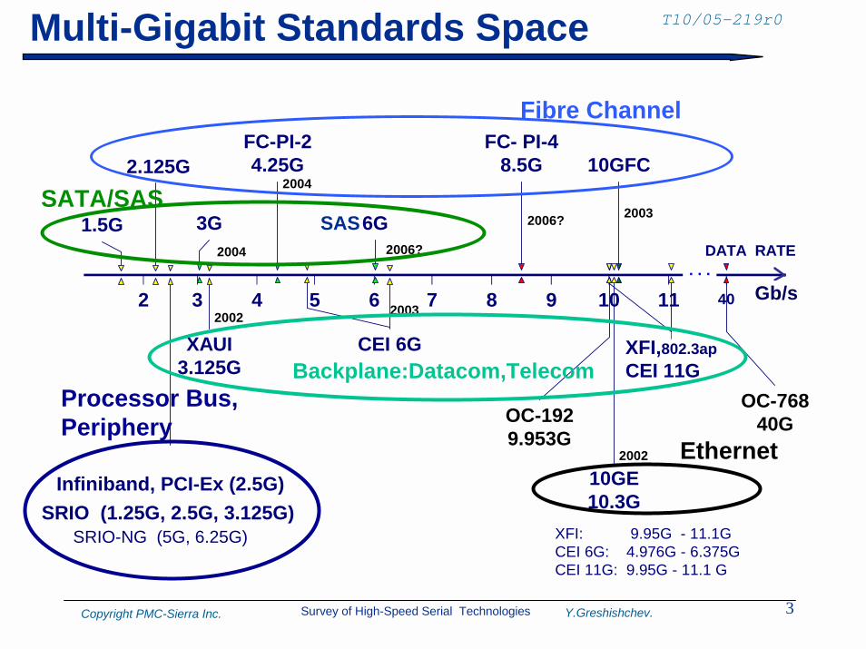
T10/05-219r0Multi-Gigabit Standards Space
2 3 4 5 6 7 8 9 10 11 12
1.5G
2.125G
XAUI3.125G
FC-PI-24.25G
FC- PI-48.5G
3G
CEI 6G
Infiniband, PCI-Ex (2.5G)
OC-1929.953G
10GE10.3G
DATA RATE
40
. . .Gb/s
OC-76840G
10GFC2004
2004
2006? 2003
2002
2002
2003
XFI,802.3apCEI 11G
6G2006?
XFI: 9.95G - 11.1GCEI 6G: 4.976G - 6.375GCEI 11G: 9.95G - 11.1 G
SRIO (1.25G, 2.5G, 3.125G) SRIO-NG (5G, 6.25G)
Fibre Channel
SATA/SAS
Ethernet
Backplane:Datacom,TelecomProcessor Bus,Periphery
SAS
Gb/s
Survey of High-Speed Serial Technologies 4Copyright PMC-Sierra Inc. Y.Greshishchev.
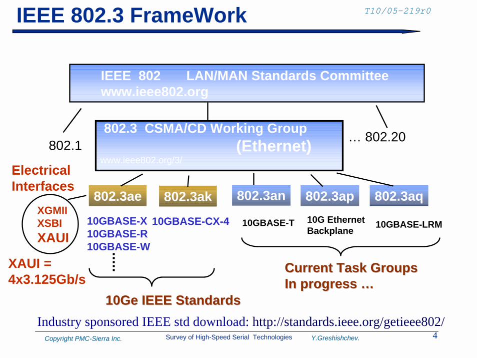
T10/05-219r0IEEE 802.3 FrameWork
IEEE 802 LAN/MAN Standards Committee www.ieee802.org
… 802.20www.ieee802.org/3/
802.3 CSMA/CD Working Group(Ethernet)802.1
10GBASE-X 10GBASE-R 10GBASE-W
10GBASE-CX-4 10GBASE-TXGMIIXSBIXAUI
ElectricalInterfaces
802.3an 802.3ap 802.3aq802.3ae 802.3ak10G EthernetBackplane 10GBASE-LRM
XAUI =4x3.125Gb/s
Current Task GroupsCurrent Task GroupsIn progress …In progress …
10Ge IEEE Standards10Ge IEEE StandardsIndustry sponsored IEEE std download: http://standards.ieee.org/getieee802/
Survey of High-Speed Serial Technologies 5Copyright PMC-Sierra Inc. Y.Greshishchev.
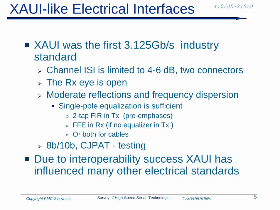
T10/05-219r0XAUI-like Electrical Interfaces
XAUI was the first 3.125Gb/s industry standard! Channel ISI is limited to 4-6 dB, two connectors! The Rx eye is open! Moderate reflections and frequency dispersion
• Single-pole equalization is sufficient» 2-tap FIR in Tx (pre-emphases)» FFE in Rx (if no equalizer in Tx )» Or both for cables
! 8b/10b, CJPAT - testingDue to interoperability success XAUI has influenced many other electrical standards
Survey of High-Speed Serial Technologies 6Copyright PMC-Sierra Inc. Y.Greshishchev.
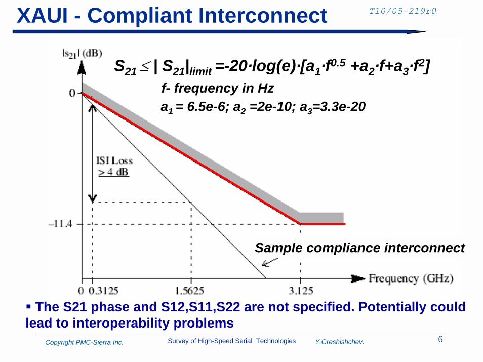
T10/05-219r0XAUI - Compliant Interconnect
a1 = 6.5e-6; a2 =2e-10; a3=3.3e-20
S21 ≤ | S21|limit =-20·log(e)·[a1·f0.5 +a2·f+a3·f2]f- frequency in Hz
Sample compliance interconnect
" The S21 phase and S12,S11,S22 are not specified. Potentially couldlead to interoperability problems
Survey of High-Speed Serial Technologies 7Copyright PMC-Sierra Inc. Y.Greshishchev.
T10/05-219r0The XFI “Ziffy”
The XFI Ziffy is the high speed serial electrical interface for XFP modules with a nominal baud rate of 9.95-11.1 Gb/s. XFI connects a serial 9.95-11.1 Gb/s SerDes to a module over 300mm of improved FR41 material or up to 200mm of standard FR4 with one connector. The electrical interface isbased on high speed low voltage AC coupled logic with a nominal differential impedance of 100 Ω. The XFP module could be an Electrical-to-Optical or an Electrical-to-Electrical device.
The XFP modules and the host system are hot-pluggable. The module or the host system shall not be damaged by unexpected insertion or removal of the module1. Standard FR4 has a typical loss tangent of 0.022, where improved FR4 such as Nelco 4000-13 has a typical loss tangent of 0.016.
Source: XFP MSA, Rev.4,2004
Survey of High-Speed Serial Technologies 8Copyright PMC-Sierra Inc. Y.Greshishchev.
T10/05-219r0XFI Impact
XFI had become de facto next milestone in H/S interfaces at 10Gb/s! Data protocol agnostic! Was also adapted by Fiber Channel and OIF 11G SR
Requires Rx FFE, no Tx equalization is allowed! Reduced EMI
Specifies advanced set of differential S-parameters to control primary and secondary reflectionsInteroperability testing with the test boards
Survey of High-Speed Serial Technologies 9Copyright PMC-Sierra Inc. Y.Greshishchev.
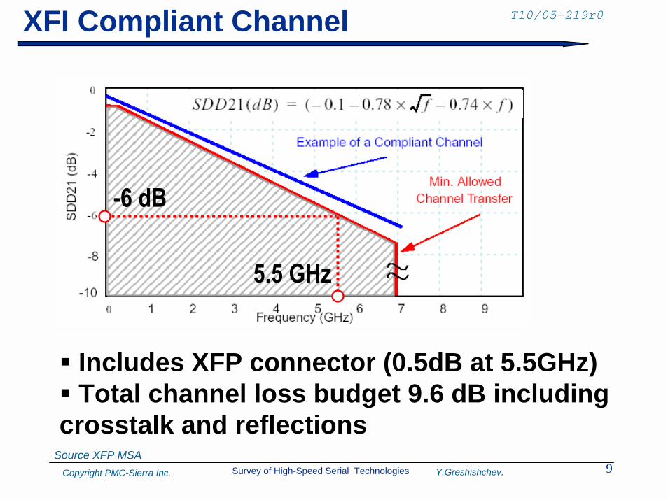
T10/05-219r0XFI Compliant Channel
5.5 GHz
-6 dB
" Includes XFP connector (0.5dB at 5.5GHz)" Total channel loss budget 9.6 dB including crosstalk and reflections
Source XFP MSA
Survey of High-Speed Serial Technologies 10Copyright PMC-Sierra Inc. Y.Greshishchev.
T10/05-219r0Optical Internetworking Forum (OIF)
• Electrical Interfaces for OC-192, OC768 • CEI 6G SR, LR (over legacy backplanes)• CEI 11G
A milestone in 6Gb/s interconnects and in advanced equalization techniques for interfaces with BER < 10-15
Has the most comprehensive up to date multi-gigabit range serial electrical interface specification with Common Electrical Interfaces (CEI) “Jitter and Interoperability MethodologyWill be covered in separate presentations
Survey of High-Speed Serial Technologies 11Copyright PMC-Sierra Inc. Y.Greshishchev.
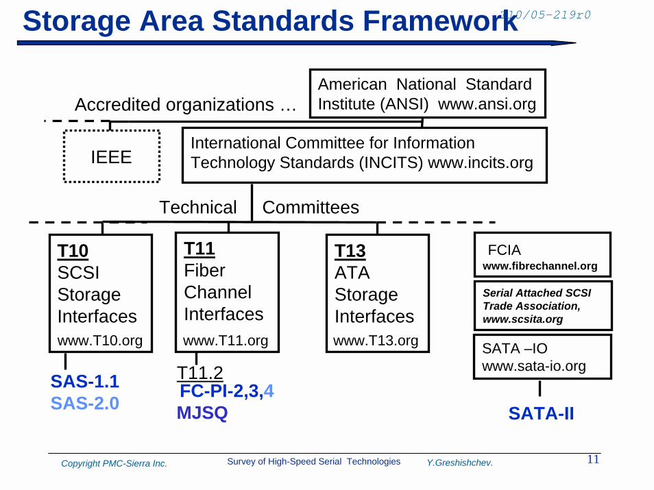
T10/05-219r0Storage Area Standards Framework
American National Standard Institute (ANSI) www.ansi.org
SATA –IOwww.sata-io.org
IEEE
Accredited organizations …
International Committee for Information Technology Standards (INCITS) www.incits.org
T10SCSIStorageInterfaces
Technical Committees
T11Fiber ChannelInterfaces
T13ATA StorageInterfaces
FCIAwww.fibrechannel.org
Serial Attached SCSITrade Association,www.scsita.org
www.T10.org www.T11.org www.T13.org
FC-PI-2,3,4MJSQ
T11.2SAS-1.1SAS-2.0 SATA-II
Survey of High-Speed Serial Technologies 12Copyright PMC-Sierra Inc. Y.Greshishchev.
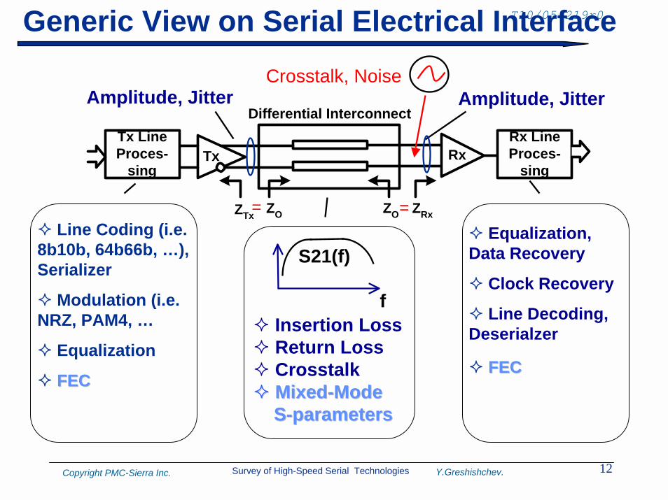
T10/05-219r0Generic View on Serial Electrical Interface
Tx Rx
Differential Interconnect
ZTx ZRx
Rx LineProces-
sing
Tx LineProces-
sing
ZO ZO
# Line Coding (i.e. 8b10b, 64b66b, …), Serializer
# Modulation (i.e. NRZ, PAM4, …
# Equalization
# FECFEC
# Equalization, Data Recovery
# Clock Recovery
# Line Decoding, Deserialzer
# FECFEC
f
S21(f)
# Insertion Loss# Return Loss# Crosstalk## MixedMixed--Mode Mode
SS--parametersparameters
Amplitude, Jitter Amplitude, JitterCrosstalk, Noise
= =
Survey of High-Speed Serial Technologies 13Copyright PMC-Sierra Inc. Y.Greshishchev.
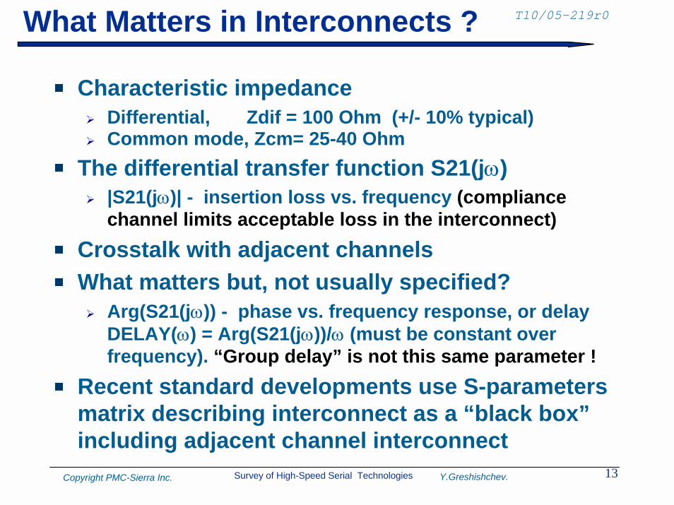
T10/05-219r0What Matters in Interconnects ?
Characteristic impedance! Differential, Zdif = 100 Ohm (+/- 10% typical)! Common mode, Zcm= 25-40 Ohm
The differential transfer function S21(jω)! |S21(jω)| - insertion loss vs. frequency (compliance
channel limits acceptable loss in the interconnect)Crosstalk with adjacent channelsWhat matters but, not usually specified?! Arg(S21(jω)) - phase vs. frequency response, or delay
DELAY(ω) = Arg(S21(jω))/ω (must be constant over frequency). “Group delay” is not this same parameter !
Recent standard developments use S-parameters matrix describing interconnect as a “black box” including adjacent channel interconnect
Survey of High-Speed Serial Technologies 14Copyright PMC-Sierra Inc. Y.Greshishchev.
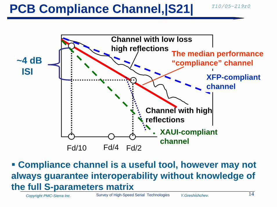
T10/05-219r0PCB Compliance Channel,|S21|
Channel with low losshigh reflections
Channel with highreflections
The median performance“compliance” channel
XAUI-compliantchannel
XFP-compliantchannel
~4 dBISI
Fd/4Fd/10 Fd/2
" Compliance channel is a useful tool, however may not always guarantee interoperability without knowledge of the full S-parameters matrix
Survey of High-Speed Serial Technologies 15Copyright PMC-Sierra Inc. Y.Greshishchev.
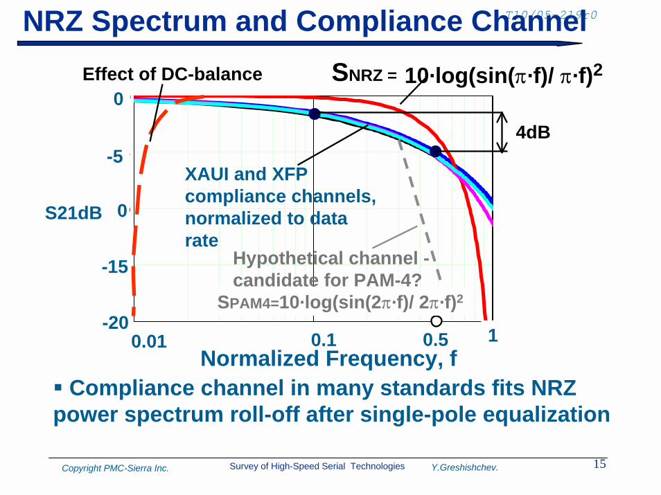
T10/05-219r0NRZ Spectrum and Compliance Channel
0.01 0.1 120
15
10
5
0
10·log(sin(π·f)/ π·f)2SNRZ =
XAUI and XFPcompliance channels,normalized to datarate
10.10.01
0
-5
-10
-15
-20
S21dB
0.5
" Compliance channel in many standards fits NRZ power spectrum roll-off after single-pole equalization
Hypothetical channel -candidate for PAM-4?
SPAM4=10·log(sin(2π·f)/ 2π·f)2
Effect of DC-balance
4dB
Normalized Frequency, f
Survey of High-Speed Serial Technologies 16Copyright PMC-Sierra Inc. Y.Greshishchev.
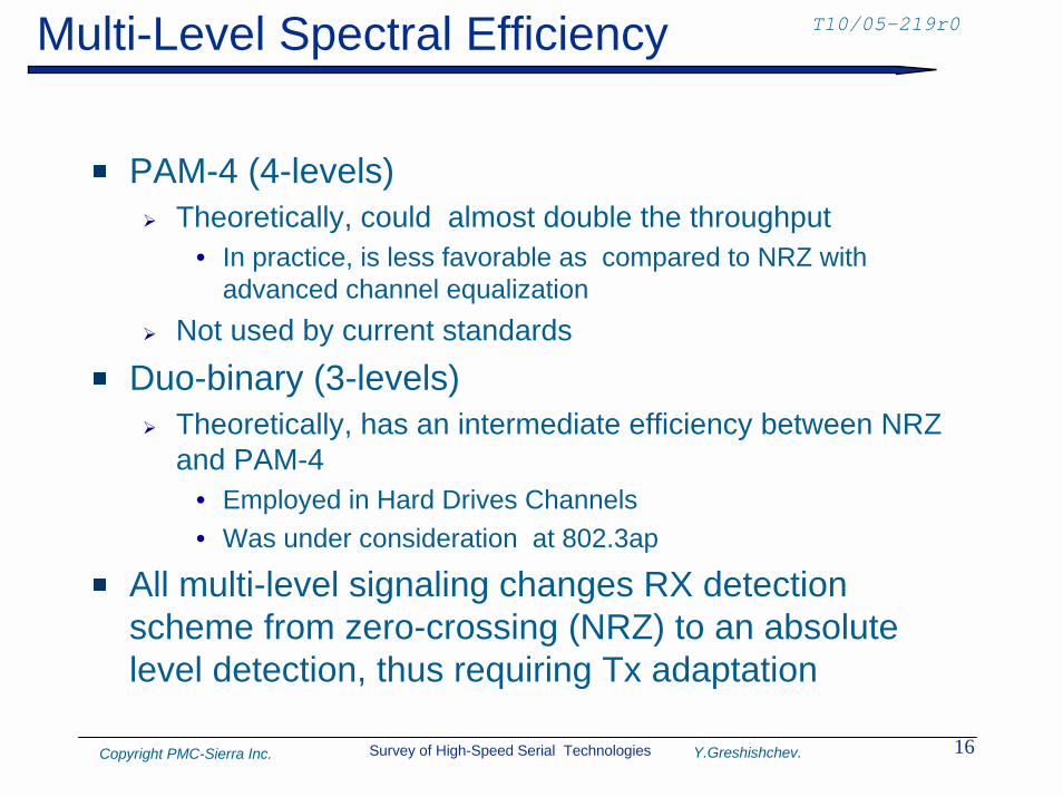
T10/05-219r0Multi-Level Spectral Efficiency
PAM-4 (4-levels)! Theoretically, could almost double the throughput
• In practice, is less favorable as compared to NRZ with advanced channel equalization
! Not used by current standards
Duo-binary (3-levels)! Theoretically, has an intermediate efficiency between NRZ
and PAM-4• Employed in Hard Drives Channels• Was under consideration at 802.3ap
All multi-level signaling changes RX detection scheme from zero-crossing (NRZ) to an absolute level detection, thus requiring Tx adaptation
Survey of High-Speed Serial Technologies 17Copyright PMC-Sierra Inc. Y.Greshishchev.
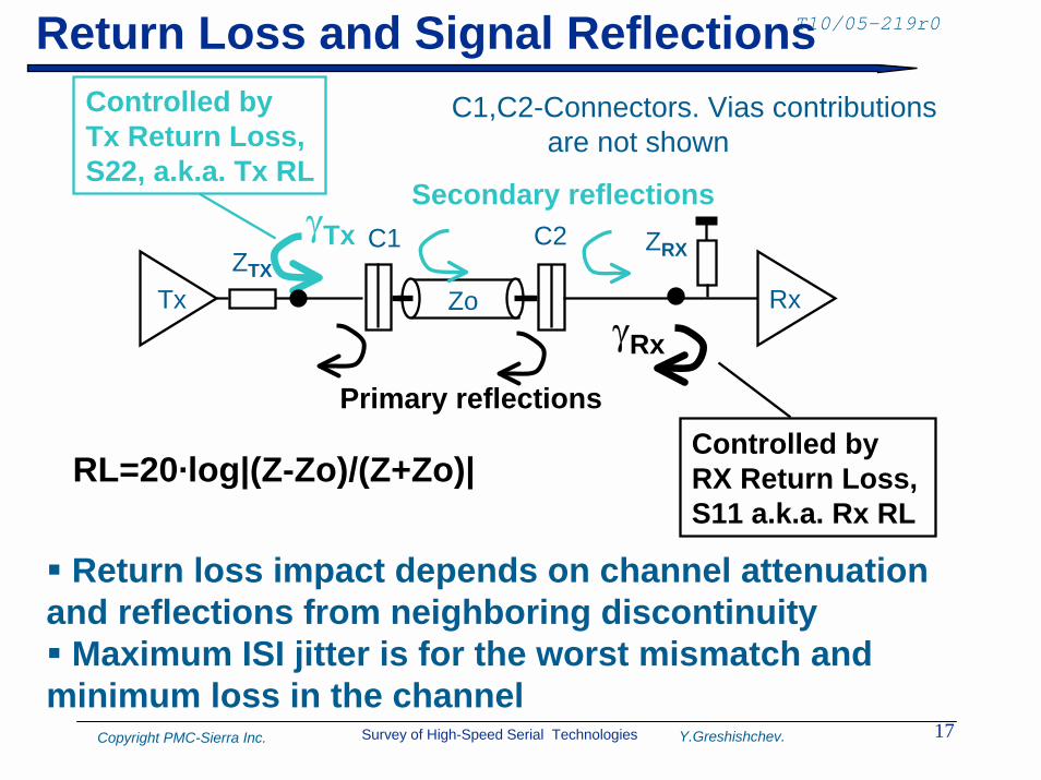
T10/05-219r0Return Loss and Signal Reflections
TxZTX
γTx
Controlled byTx Return Loss,S22, a.k.a. Tx RL
C1,C2-Connectors. Vias contributionsare not shown
Rx
ZRX
γRx
C1 C2
Zo
Secondary reflections
Primary reflectionsControlled byRX Return Loss,S11 a.k.a. Rx RL
RL=20·log|(Z-Zo)/(Z+Zo)|
" Return loss impact depends on channel attenuation and reflections from neighboring discontinuity" Maximum ISI jitter is for the worst mismatch and minimum loss in the channel
Survey of High-Speed Serial Technologies 18Copyright PMC-Sierra Inc. Y.Greshishchev.
T10/05-219r0Jitter Methodologies
Fiber Channel Methodology for Jitter and Signal Quality Specification – MJSQ (MJS-1999, MJSQ, rev14 -2004)! Deals with the “Open Eye” interfaces! Originally was developed to serve FC specifications,
however has become an industry wide methodology! Defines jitter components, Tx,Rx measurement methods
Statistical Eye (OIF)! Was mainly developed to target “Closed Eye” interfaces
with BER requirement <10-15-10-18. Based on analytical BER simulation technique (“StatEye”) with 5-tap ideal DFE to open the eye and S-parameters to represent the “channel”
! StatEye.org is a non-profit open source forum. Operates under the open source license agreement. www.StatEye.org
Survey of High-Speed Serial Technologies 19Copyright PMC-Sierra Inc. Y.Greshishchev.
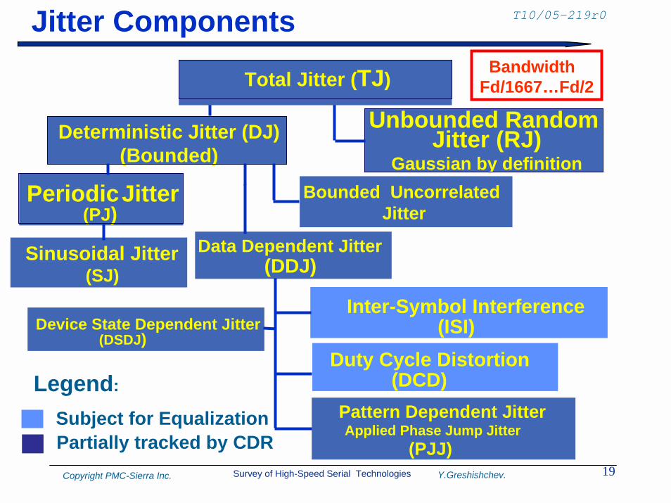
T10/05-219r0Jitter Components
Sinusoidal Jitter(SJ)
Duty Cycle Distortion(DCD)
PeriodicJitter(PJ)
Data Dependent Jitter(DDJ)
Device State Dependent Jitter(DSDJ)
Bounded Uncorrelated Jitter
Deterministic Jitter (DJ)(Bounded)
Unbounded Random Jitter (RJ)
Gaussian by definition
Inter-Symbol Interference (ISI)
BandwidthFd/1667…Fd/2Total Jitter (TJ)
Legend:
Applied Phase Jump Jitter(PJJ)
Pattern Dependent JitterSubject for EqualizationPartially tracked by CDR
Survey of High-Speed Serial Technologies 20Copyright PMC-Sierra Inc. Y.Greshishchev.
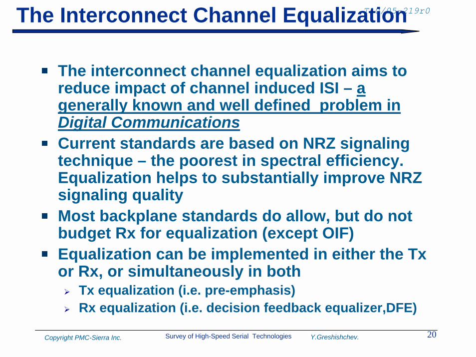
T10/05-219r0The Interconnect Channel Equalization
The interconnect channel equalization aims to reduce impact of channel induced ISI – a generally known and well defined problem in Digital CommunicationsCurrent standards are based on NRZ signaling technique – the poorest in spectral efficiency. Equalization helps to substantially improve NRZ signaling qualityMost backplane standards do allow, but do not budget Rx for equalization (except OIF)Equalization can be implemented in either the Tx or Rx, or simultaneously in both! Tx equalization (i.e. pre-emphasis)! Rx equalization (i.e. decision feedback equalizer,DFE)
Survey of High-Speed Serial Technologies 21Copyright PMC-Sierra Inc. Y.Greshishchev.
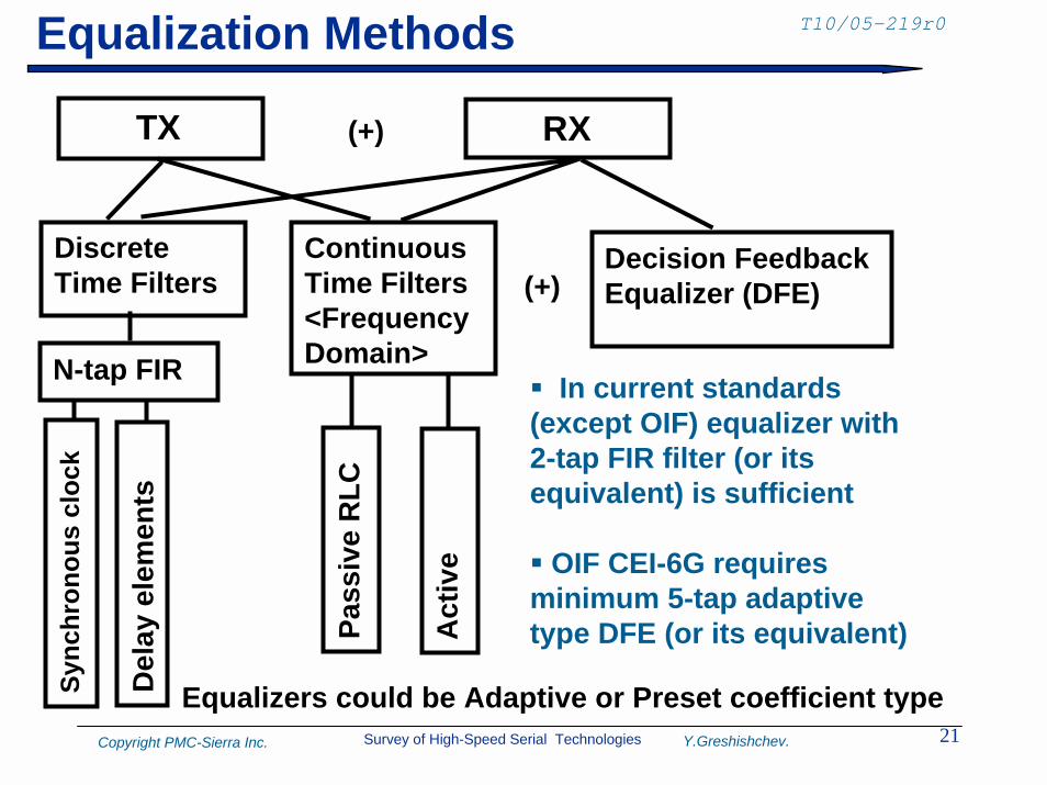
T10/05-219r0Equalization Methods
TX RX
Discrete Time Filters
ContinuousTime Filters<FrequencyDomain>
Sync
hron
ous
cloc
k
Del
ay e
lem
ents
Pass
ive
RLC
Act
ive
" In current standards (except OIF) equalizer with 2-tap FIR filter (or its equivalent) is sufficient
" OIF CEI-6G requires minimum 5-tap adaptive type DFE (or its equivalent)
Equalizers could be Adaptive or Preset coefficient type
N-tap FIR
(+)
Decision FeedbackEqualizer (DFE)(+)
Survey of High-Speed Serial Technologies 22Copyright PMC-Sierra Inc. Y.Greshishchev.
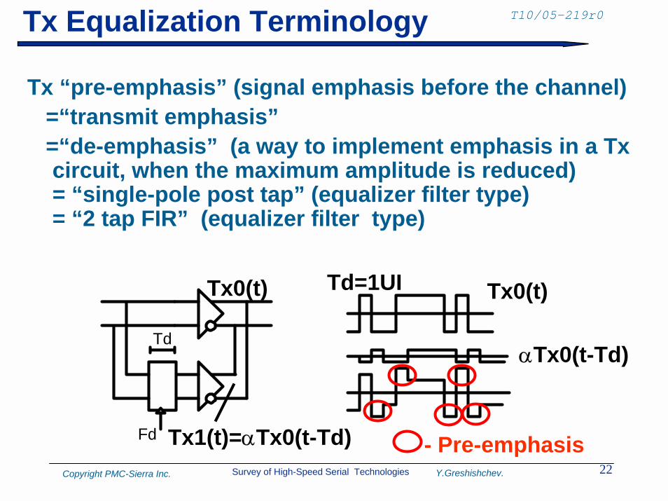
T10/05-219r0Tx Equalization Terminology
Tx “pre-emphasis” (signal emphasis before the channel)=“transmit emphasis”=“de-emphasis” (a way to implement emphasis in a Tx circuit, when the maximum amplitude is reduced)= “single-pole post tap” (equalizer filter type)= “2 tap FIR” (equalizer filter type)
Td
Fd
Tx0(t)
Tx1(t)=αTx0(t-Td)
Tx0(t)
αTx0(t-Td)
Td=1UI
- Pre-emphasis
Survey of High-Speed Serial Technologies 23Copyright PMC-Sierra Inc. Y.Greshishchev.
T10/05-219r0The FIR Filter
The "FIR" means "Finite Impulse Response". The impulse response is "finite" because there is no feedback in the filter: only delayed inputs are taken to construct the filter outputIn opposite to“IIR” (Infinite IR), where filter output is used to construct filter response and it may become infiniteThe "impulse response" of a FIR filter is actually just the set of FIR coefficientsImportant feature of FIR is a linear phase responseTransversal Filter - another name for a FIR filter implementation
Survey of High-Speed Serial Technologies 24Copyright PMC-Sierra Inc. Y.Greshishchev.
T10/05-219r0Rx-equalization
A simple equalizer is an amplifier with boosted high frequency gain at Fd/2! Useful, if signal comes from not-equalized Tx or, if
working in conjunction with Tx equalization! Subject for SNR degradation
A Feed Forward Equalizer (FFE) equalizer uses a parallel combination of “flat gain” amplifier and “boost amplifier”! In FFE equalizer with adaptation the gain is varied,
based on the measured power in the frequency band of interest
An FFE type equalizer some times is used in front of DFE and/or clock recovery path to “pre-open” the eye
Survey of High-Speed Serial Technologies 25Copyright PMC-Sierra Inc. Y.Greshishchev.
T10/05-219r0Step, Pulse and Impulse Responses
Step response – is a system response on a step function 1(t)
Impulse response - is a system response on δ-function, that is a derivative of the step response! TDR is based on impulse response
! Impulse response is an IFFT of S21(f)
Pulse response – is a system response on a pulse width equal to a bode interval
All parameters are interrelated according to linear system theory
Survey of High-Speed Serial Technologies 26Copyright PMC-Sierra Inc. Y.Greshishchev.
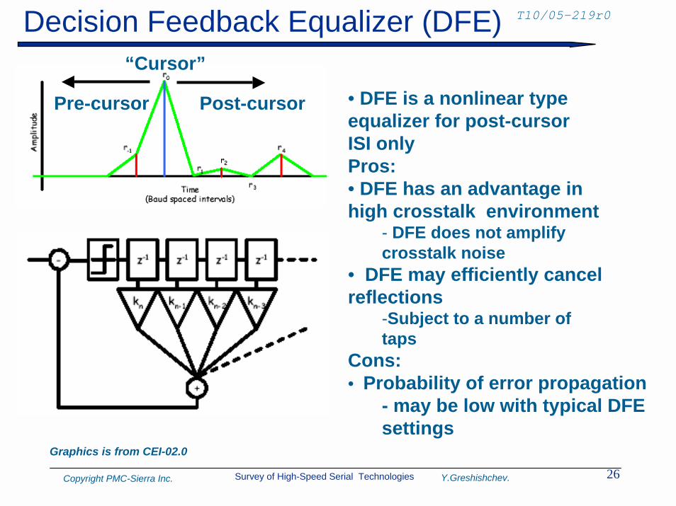
T10/05-219r0Decision Feedback Equalizer (DFE)“Cursor”
Post-cursorPre-cursor • DFE is a nonlinear typeequalizer for post-cursorISI onlyPros:• DFE has an advantage in high crosstalk environment
- DFE does not amplifycrosstalk noise
• DFE may efficiently cancelreflections
-Subject to a number oftaps
Cons:• Probability of error propagation
- may be low with typical DFE settings
Graphics is from CEI-02.0
Survey of High-Speed Serial Technologies 27Copyright PMC-Sierra Inc. Y.Greshishchev.
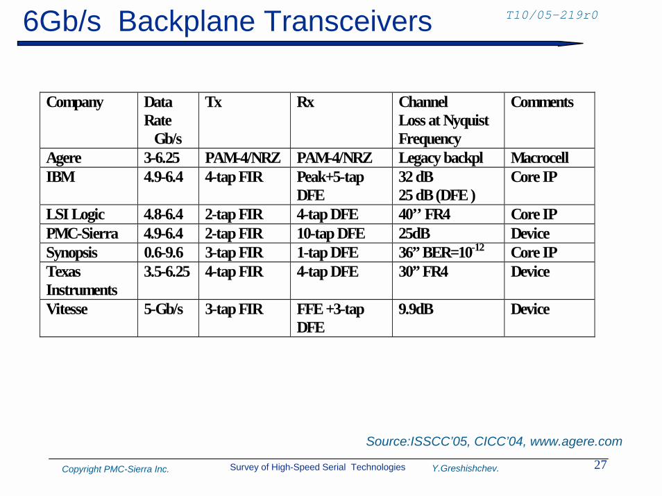
T10/05-219r06Gb/s Backplane Transceivers
Company Data Rate Gb/s
Tx Rx Channel Loss at Nyquist Frequency
Comments
Agere 3-6.25 PAM-4/NRZ PAM-4/NRZ Legacy backpl Macrocell IBM 4.9-6.4 4-tap FIR Peak+5-tap
DFE 32 dB 25 dB (DFE )
Core IP
LSI Logic 4.8-6.4 2-tap FIR 4-tap DFE 40’’ FR4 Core IP PMC-Sierra 4.9-6.4 2-tap FIR 10-tap DFE 25dB Device Synopsis 0.6-9.6 3-tap FIR 1-tap DFE 36” BER=10-12 Core IP Texas Instruments
3.5-6.25 4-tap FIR 4-tap DFE 30” FR4 Device
Vitesse 5-Gb/s 3-tap FIR FFE +3-tap DFE
9.9dB Device
Source:ISSCC’05, CICC’04, www.agere.com
Survey of High-Speed Serial Technologies 28Copyright PMC-Sierra Inc. Y.Greshishchev.
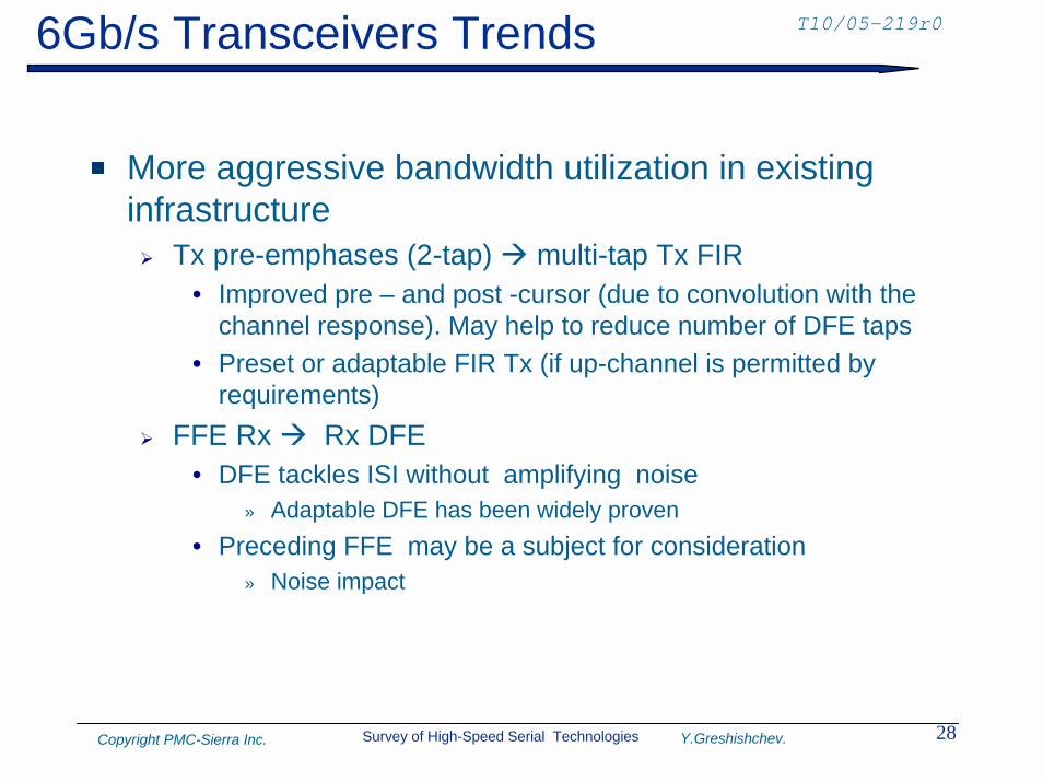
T10/05-219r06Gb/s Transceivers Trends
More aggressive bandwidth utilization in existing infrastructure! Tx pre-emphases (2-tap) $ multi-tap Tx FIR
• Improved pre – and post -cursor (due to convolution with the channel response). May help to reduce number of DFE taps
• Preset or adaptable FIR Tx (if up-channel is permitted by requirements)
! FFE Rx $ Rx DFE• DFE tackles ISI without amplifying noise
» Adaptable DFE has been widely proven • Preceding FFE may be a subject for consideration
» Noise impact
Survey of High-Speed Serial Technologies 29Copyright PMC-Sierra Inc. Y.Greshishchev.
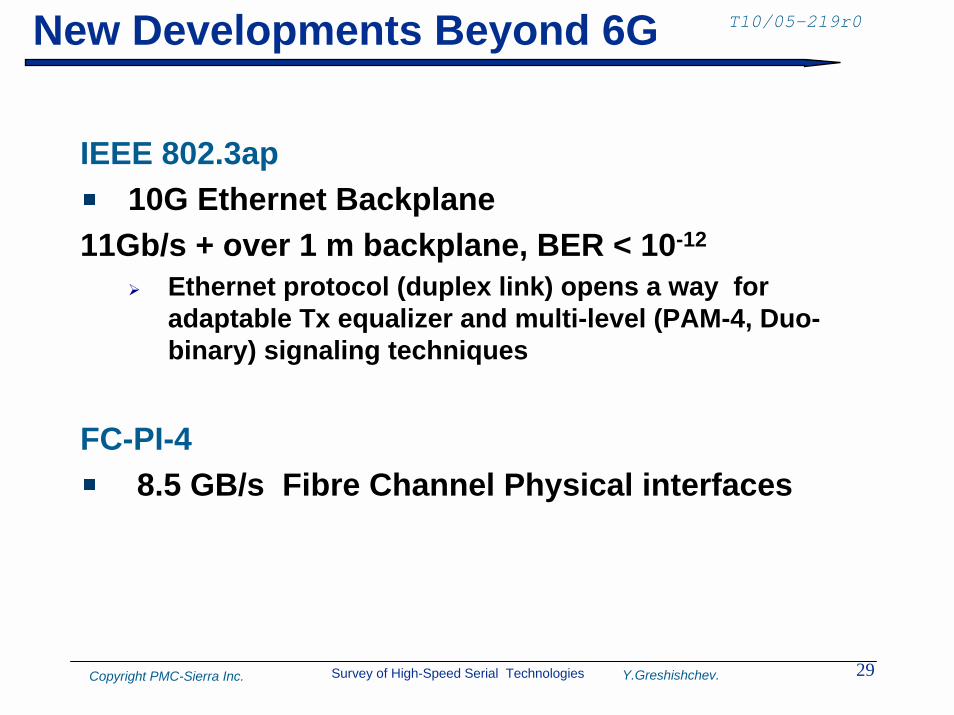
T10/05-219r0New Developments Beyond 6G
IEEE 802.3ap10G Ethernet Backplane
11Gb/s + over 1 m backplane, BER < 10-12
! Ethernet protocol (duplex link) opens a way for adaptable Tx equalizer and multi-level (PAM-4, Duo-binary) signaling techniques
FC-PI-48.5 GB/s Fibre Channel Physical interfaces
Recommended