Synchronous Boosters forSingle Frequency Networking
and MaxxCastingAugust 2015
Copyright © 2015 GatesAir, Inc. All rights reserved.
FeaturingGatesAir’s
Tim AndersonRadio Product & Business Development Manager

Proprietary and confidential. | 1
Connecting What’s Next
Connecting What’s Next
Synchronous Boosters for Single Frequency Networking and MaxxCastingTimothy B. Anderson, CPBE, DRB, CBNERadio Product Development Manager
1

Proprietary and confidential. | 2
Connecting What’s Next
Geo Broadcast Solutions, LLC-- Confidential Proprietary 2
Background
Most are familiar with on-frequency repeaters (boosters)
• Many recall stories of unsatisfactory performance• Some created more problems than they solved
– Distorted audio (multipath)– Weak coverage– Interference to primary transmitter’s signal
• Some were problematic and were turned off

Proprietary and confidential. | 3
Connecting What’s Next
Main Contour Main Transmitter
Hill or Mountain
Booster Signal Interference w/ Main Signal on the Edges of Booster Contour
High levels of interference on the fringes of the booster contour (such as static, distortion, mulltipath) can cause listeners to choose to limit their listening to the station.
Traditional “Single Booster” Design
Historically, broadcasters have used single booster sites with relatively high antenna heights to fill in areas where their main signal is blocked by terrain.
While the single site, tall tower booster does fill in the terrain blocked area, it can often create interference with the main signal in areas that are covered by both the main and booster signals.

Proprietary and confidential. | 4
Connecting What’s Next
What is MaxxCasting™?
Geo-Broadcast Solutions (“GBS”) has developed the MaxxCasting System that combines radio and cellular technology to enable FM Broadcasters using boosters to enhance their signals by reducing multipath interference between the main and booster transmissions through the use of a cluster of low to the ground, high power, highly directionalized synchronized booster sites.
GBS is working in partnership with GatesAir to provide the MaxxCasting design and related equipment for broadcasters to improve existing booster problems.
The use of multiple boosters to broadcast the same content as the main is permitted by the FCC.
GBS has filed for a patent on the MaxxCasting System.

Proprietary and confidential. | 5
Connecting What’s Next
Geo Broadcast Solutions, LLC-- Confidential Proprietary 5Background
MaxxCasting is an FM SFN repeater system, but that is where similarity ends…• Brings some new technologies to SFN repeater networks to resolve
performance issues◦ Research into parameters that determine simulcast interference◦ Advanced geographic tools to intelligently design repeater networks
Calculates coverage, population, signal levels and shows interference areas, deducts total population factoring interference areas
Includes buildings as well as terrain
Proprietary and confidential. | 6
Connecting What’s Next
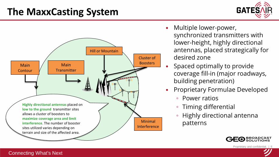
The MaxxCasting System
Main Contour
Main Transmitter
Hill or Mountain
Highly directional antennas placed on low to the ground transmitter sites allows a cluster of boosters to maximize coverage area and limit interference. The number of booster sites utilized varies depending on terrain and size of the affected area.
Cluster of Boosters
Minimal Interference
Multiple lower-power, synchronized transmitters with lower-height, highly directional antennas, placed strategically for desired zone
Spaced optimally to provide coverage fill-in (major roadways, building penetration)
Proprietary Formulae Developed◦ Power ratios ◦ Timing differential◦ Highly directional antenna
patterns

Proprietary and confidential. | 7
Connecting What’s Next
Geo Broadcast Solutions, LLC-- Confidential Proprietary 7Highly Directional Antennas
FM 87.5-108 MHzElement Gain 7.5 dBInput power 5 kWVSWR ≤1.3:1Polarization Vertical, Horizontal or SlantInput Connector 7/8” EIA

Proprietary and confidential. | 8
Connecting What’s Next
Geo Broadcast Solutions, LLC-- Confidential Proprietary 8Typical MaxxCasting System

Proprietary and confidential. | 9
Connecting What’s Next
Effects of RF Simulcasting
Broadcasting from two or more transmitters on the same frequency can lead to reception problems in the overlap areas – the areas in which the RF signal level from multiple transmitters is within ~3dB
Precise synchronization of the RF carrier frequency and stereo pilot phase is required to prevent RF signal interference in the overlap region

Proprietary and confidential. | 10
Connecting What’s Next
Geo Broadcast Solutions, LLC-- Confidential Proprietary 10
FM Carrier frequency, Stereo Pilot Phase and from different transmitters and Audio signal delay needs to be precisely aligned in the overlap region.
Keep radiation going in line with main signal, don’t cross it or point towards it
Keep identical equipment in the chain at all sites (i.e. exciters; use common processor)
Frequency and modulation synchronized with each other & primary transmitter using GatesAir IP-200 with Synchrocast®
Distribution to sites must be stable (i.e. not the Public Internet); can be T1 or IP and compression may be used to limit bandwidth
Requirements to Achieve Signal Alignment

Proprietary and confidential. | 11
Connecting What’s Next3-Dec-15
Requirements to Achieve Signal Alignment Delay of the signal leaving the studio to the receiver in the overlap region must
be precisely aligned between sites The signal leaving the studio experiences both uncontrolled STL network delay
as well as several constant delays Constant delays includes processing within the various elements in the signal
chain and the RF “flight” time in the air RF “flight” time is calculated based on speed of light ~300,000 km/hr The Exciters must produce constant processing delay and have the ability to
lock the carrier and pilot with a GPS reference GatesAir’s Flexiva and Flexstar line of Exciters satisfy this requirement System Engineering activity to perform path study and delay measurements

Proprietary and confidential. | 12
Connecting What’s Next
SynchroCast Target Delay Adjustment - Example Audio signal delay also needs to be precisely aligned in the overlap region Adjust Target Delay to move the signal delay to the overlap area Delay difference of 3.3525 µs moves the equal delay point 1 km
Capture Area Capture AreaOverlap Area
Transmitter 1 Transmitter 2
STL
Studio
Equal Signal Line Equal Delay Line

Proprietary and confidential. | 13
Connecting What’s Next13
What is the role of SynchroCast?
GPS Timing
GPS Timing
GPS Timing
GPS Timing GPS Timing
STL B (Target Delay managed by SynchroCast) Transmitter B – Delay Constant
Analog/Digital/AES-192
Multicast/Multi-Unicast
Wide Area IP Network(s)
Console/AudioProcessor
STL A
STL B
STL A (Target Delay managed by SynchroCast) Transmitter A – Delay constant
To keep audio alignment, GatesAir’s SynchroCast system will keep a constant, precise, and user settable STL delay of the signal from studio ingest to output at each transmitter site
Managing the delay across an IP STL is the most challenging aspect of signal alignment Use of GPS timing reference is key element for precision delay SynchroCast works with Analog, Digital and Digital MPX - AES 192
Analog/Digital/AES-192
Analog/Digital/AES-192

Proprietary and confidential. | 14
Connecting What’s Next
Exciter
Tx 2
GPS
IP Link 200
Example: Equalize 2 STLs to 100 msec signal delay
Studio
GPS
IP Link 200IP
Multicast
Exciter
Tx 1
GPS
IP Link 200
SynchroCast Target Delay Adjustment - ExampleSTL Delay = 75.4 msecTarget Delay = 100 msec
SynchroCast Delay =100 – 75.4 = 24.6 msec
STL Delay = 35.3 msecTarget Delay = 100 msec
SynchroCast Delay =100 – 35.3 = 64.7 msec
Proprietary and confidential. | 15
Connecting What’s Next3-Dec-15
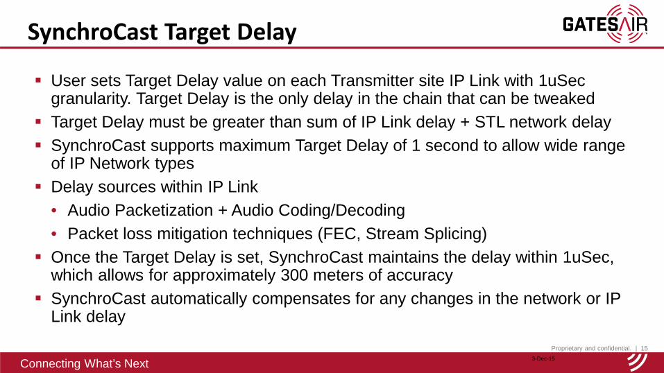
SynchroCast Target Delay
User sets Target Delay value on each Transmitter site IP Link with 1uSec granularity. Target Delay is the only delay in the chain that can be tweaked
Target Delay must be greater than sum of IP Link delay + STL network delay SynchroCast supports maximum Target Delay of 1 second to allow wide range
of IP Network types Delay sources within IP Link
• Audio Packetization + Audio Coding/Decoding• Packet loss mitigation techniques (FEC, Stream Splicing)
Once the Target Delay is set, SynchroCast maintains the delay within 1uSec, which allows for approximately 300 meters of accuracy
SynchroCast automatically compensates for any changes in the network or IP Link delay

Proprietary and confidential. | 16
Connecting What’s Next
Overcoming IP network impairments, especially when using ISP networks• Variation in network delay• Packet losses
Isolated packet losses will not cause Synchrocast to lose lock on Target Delay Packet losses can however degrade audio quality – more severe with
compressed audio SynchroCast works with IP Link transport reliability techniques
• RTP/UDP Level FEC – Effective on random packet loss patterns• Intraplex Stream Splicing (Time and Network Diversity) – Effective for burst
packet losses• Stream grouping allows concatenation of techniques
Use Intraplex LiveLook to analyze the network and select the appropriate reliability option(s)
Challenges with IP Network Transport
Proprietary and confidential. | 17
Connecting What’s Next17
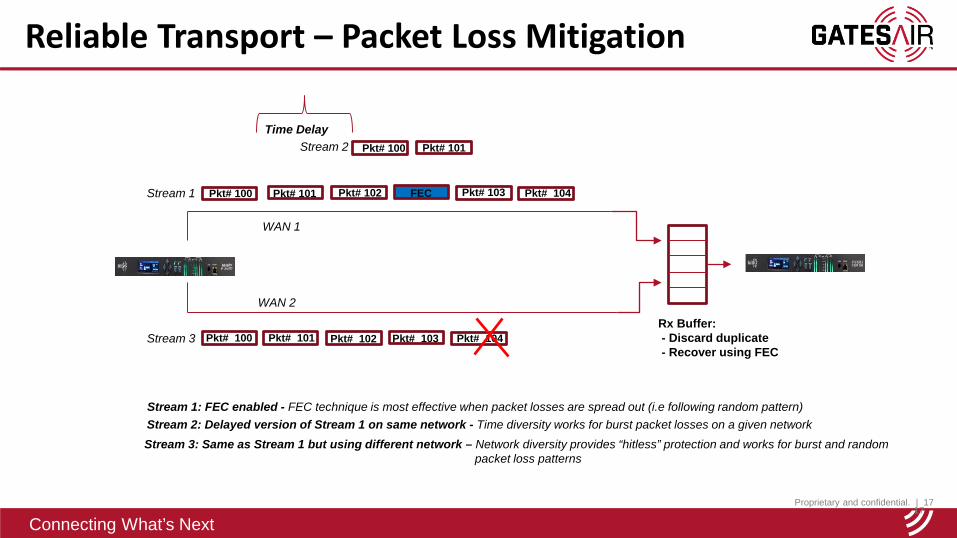
Reliable Transport – Packet Loss Mitigation
Pkt# 100
Pkt# 100
Pkt# 100 Pkt# 101
Pkt# 101
Time Delay
Pkt# 102 FEC
Rx Buffer:- Discard duplicate- Recover using FEC
Pkt# 103
Pkt# 101 Pkt# 102 Pkt# 103 Pkt# 104
WAN 1
WAN 2
Stream 1
Stream 2
Stream 3
Pkt# 104
Stream 1: FEC enabled - FEC technique is most effective when packet losses are spread out (i.e following random pattern)Stream 2: Delayed version of Stream 1 on same network - Time diversity works for burst packet losses on a given network
Stream 3: Same as Stream 1 but using different network – Network diversity provides “hitless” protection and works for burst and random packet loss patterns

Proprietary and confidential. | 18
Connecting What’s Next
Intraplex® LiveLook – Network Analytics
• Network analytics and logging application
• Analyzes packet loss patterns and recommends mitigation option
• Email notification option
• Separate network event logging to help navigate historical data
PC Application
Periodic statistics message
Proprietary and confidential. | 19
Connecting What’s Next
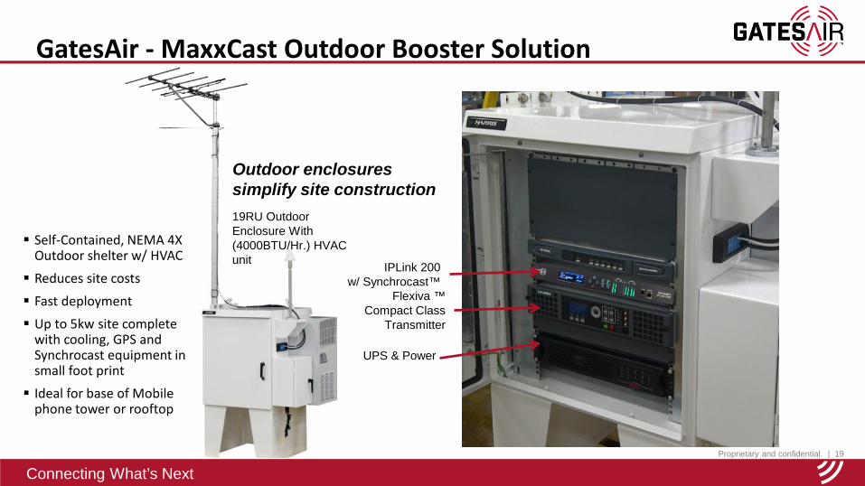
GatesAir - MaxxCast Outdoor Booster Solution
Flexiva ™ Compact Class
Transmitter
IPLink 200w/ Synchrocast™
UPS & Power
19RU Outdoor Enclosure With (4000BTU/Hr.) HVAC unit
Outdoor enclosures simplify site construction
Self-Contained, NEMA 4X Outdoor shelter w/ HVAC Reduces site costs
Fast deployment Up to 5kw site complete
with cooling, GPS and Synchrocast equipment in small foot print Ideal for base of Mobile
phone tower or rooftop

Proprietary and confidential. | 20
Connecting What’s Next
Geo Broadcast Solutions, LLC-- Confidential Proprietary 20
Case Study – WSUN Clearwater, Florida
WSUN MaxxCasting installation at the Studio STL tower w/Shively Dual 6025 antennas

Proprietary and confidential. | 21
Connecting What’s Next
Geo Broadcast Solutions, LLC-- Confidential Proprietary 21
Current Coverage
WSUN Channel: 246C2 97.1 MHzHoliday, Florida
Effective Radiated Power: 11.5 kW Antenna Center HAAT: 224 m
Omni-Directional Antenna
60 dBu Contour
0.8 kW MAX ERP for MaxxCasting Node
Case Study – WSUN Clearwater, Florida

Proprietary and confidential. | 22
Connecting What’s Next
Geo Broadcast Solutions, LLC-- Confidential Proprietary 22
WSUNArea of Concern:
St, Petersburg
Case Study – WSUN Clearwater, Florida

Proprietary and confidential. | 23
Connecting What’s Next
Geo Broadcast Solutions, LLC-- Confidential Proprietary 23
Case Study #2
WSUN-FM Studio Node
Signal Level Color Population Studio Difference37 dBµV/m (mono) Blue 2,367,353 2,426,697 59,344 47 dBµV/m (stereo) Green 1,032,700 1,081,629 48,929 65 dBµV/m (indoor) Yellow 183,319 191,804 8,485
Coverage Numbers less Interference
Magenta
Studio Node (stereo)Dual Log Periodic
ERP: 800WAGL: 26m
Case Study – WSUN Clearwater, Florida

Proprietary and confidential. | 24
Connecting What’s Next
Geo Broadcast Solutions, LLC-- Confidential Proprietary 24
WSUN-FM Studio Three Node Coverage
and Interference
60 dBu Contours
Simulcast Interference(Magenta)
(Note, 2nd Node and Translator are proposed)
Case Study – WSUN Clearwater, Florida

Proprietary and confidential. | 25
Connecting What’s Next
Geo Broadcast Solutions, LLC-- Confidential Proprietary 25
WSUN-FM StudioThree Node
Coverage Improvement
60 dBu Contours
(Note, 2nd Node and Translator are proposed)
Simulcast Interference(Magenta)
Note: Interference where a low quality signal previously existed should not be considered NEW
signal degradation
Case Study – WSUN Clearwater, Florida

Proprietary and confidential. | 26
Connecting What’s Next
Geo Broadcast Solutions, LLC-- Confidential Proprietary 26
Tim Anderson, CPBE/DRB/CBNERadio Product Development and Business ManagerP: (859) 445-7135| [email protected]
Hal Kneller, CBPEVP Sales & Business DevelopmentP: (941) 391-1958 | [email protected]
Recommended