T0-1
Chapter 10 – Electrical, Antenna Structure and RF Safety Practices
• Open and Short Circuits• Electrical Safety• Grounding• RF Environmental Safety Practices• RF Awareness Guidelines• Maximum Permissible Exposure (MPE) Limits• Limiting RF Exposure
T0-2
Normal, Open and Short Circuits
• Normal Circuit– When normal current is flowing through the circuit
• Open Circuit– When the current flow is interrupted by switch or fuse
– Circuit break presents an extremely high resistance.
• Short Circuit– When the current flowing through the circuit is
following a “shorter” low resistance path between the power source terminals.
– Allows high current to flow in the circuit

T0-3
Normal, Open and Short Circuits
RE
+
I
SW
Short Circuit
Short circuit is a very low resistance path across voltage source.
Current can be very high and possibly result in a fire.
A fuse in the circuit can protect against a short circuit condition by forming an open circuit.
RE
+
I=E/R
SW
Normal Circuit
RE
+
I=0
SW
Open Circuit
T0-4
Fuses
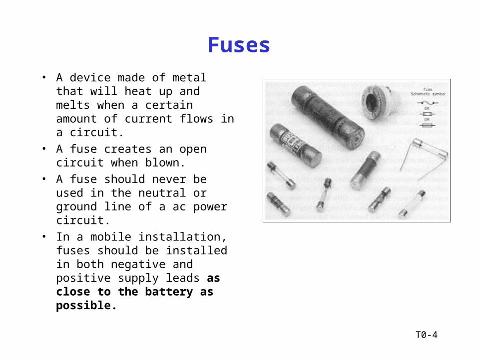
• A device made of metal that will heat up and melts when a certain amount of current flows in a circuit.
• A fuse creates an open circuit when blown.
• A fuse should never be used in the neutral or ground line of a ac power circuit.
• In a mobile installation, fuses should be installed in both negative and positive supply leads as close to the battery as possible.
T0-5
Electrical Safety Guidelines
• A main station power switch should be used to turn off all equipment at once.
• Never operate equipment without proper shields installed over all circuit components.– A safety interlock can be used to automatically turn off
power when a shield or cover is removed.
• High voltage power capacitors may remain charged even if power has been turned off.– Should be manually discharged before servicing
equipment.
T0-6
Electrical Safety Guidelines (Cont’d)
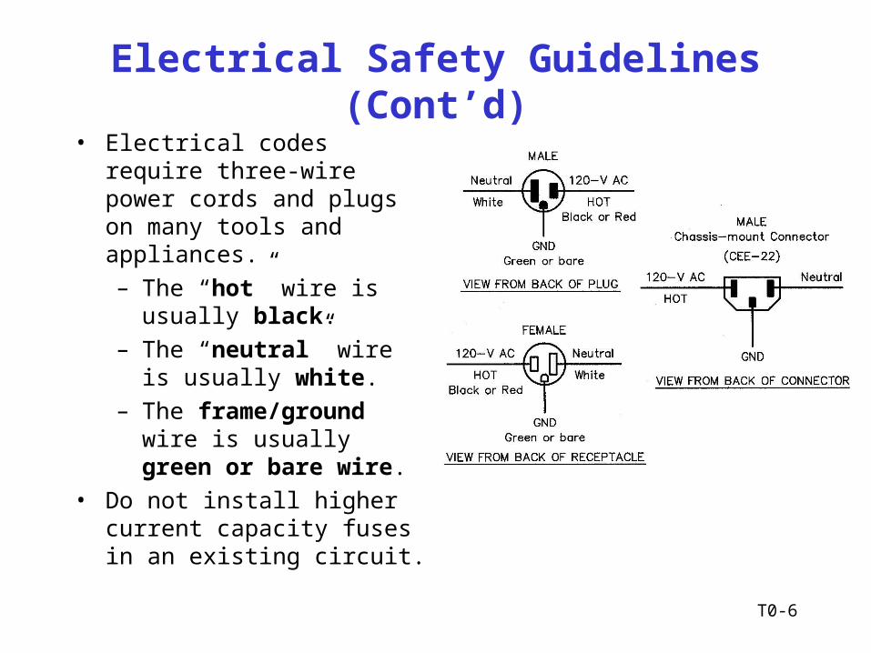
• Electrical codes require three-wire power cords and plugs on many tools and appliances.
– The “hot” wire is usually black.
– The “neutral” wire is usually white.
– The frame/ground wire is usually green or bare wire.
• Do not install higher current capacity fuses in an existing circuit.

T0-7
Electrical Safety Guidelines (Cont’d)
• Antenna/tower safety– Always wear a safety belt in good condition, a helmet
and safety glasses when climbing a tower.
– Do not stand under a tower when someone is climbing
– Keep antennas and towers away from electrical power lines.
• Always respect electricity– As little as 100 mA of current can be fatal.
– The minimum voltage that can be dangerous to humans is 30 volts.
T0-8
Antenna and Tower Installation
• Antenna Installation– Make sure no one can come in contact with the antenna
– Make sure that the antenna can never touch a power line, especially if it breaks or falls.
– Antenna height considerations are more restrictive near airports
– Stainless steel hardware is often used in antenna construction as it resists corrosion.
• Tower Installation– Guy wires for towers must be installed per manufacture's
recommendation
– Crank up towers must never be climbed except when it is in it’s fully lowered condition

T0-9
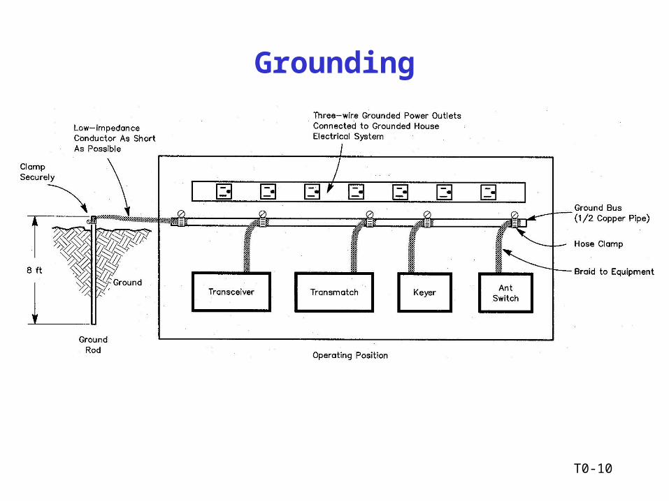
Grounding
• All station equipment should be connected to a good ground.– The best ground is provided by ground rods located
near the station.
– All rods must be connected together to form a single grounding system.
• All antennas, feed lines and rotor cables should be grounded for effective lightning protection– The best protection is to disconnect all cables and
ground the cables.
T0-10
Grounding

T0-11
RF Environmental Safety Practices
While Amateur radio is a safe activity, there has been considerable discussion and concern in recent years about the possible hazards of electro-magnetic radiation (EMR) including both RF energy and power frequency (50-60 Hz) electromagnetic fields.
T0-12
RF Environmental Safety Practices
• RF Energy– RF energy is electric and magnetic energy between 3
kHz and 300 GHz.
– RF and 60 Hz fields are nonionizing radiation. X-rays, gamma rays and some ultraviolet radiation are classified as ionizing radiation.
• Thermal Effects– RF exposure limits for the human body is frequency
dependent.
– Amateur RF exposure for SSB and CW operations is reduced due to low transmission duty cycles.
T0-13
RF Awareness Guidelines
• Confine antenna radiation to the radiating elements. Provide a single, good station ground, and eliminate radiation from transmission lines. Use good coaxial cable, not open-wire lines or end-fed antennas that come directly into the transmitter area.
• No person should near any transmitting antenna while it is in use. This is especially true for mobile or ground mounted vertical antennas. Avoid transmitting with more than 25 watts in a VHF mobile installation unless it is possible to first measure the RF fields inside the vehicle. At the 1 KW level, both HF and VHF directional antennas should be at least 35 ft above inhabited areas. Avoid using indoor and attic-mounted antennas if at all possible.
T0-14
RF Awareness Guidelines (Cont’d)
• Don’t operate high-power amplifiers with the covers removed, especially at VHF/UHF frequencies.
• Never look into the open end of an activated UHF/SHF length of microwave waveguide or point it toward anyone. Never point a high-gain, narrow-bandwidth antenna toward people. Use caution if aiming an EME array toward the horizon.
• When using hand-held transceivers, keep the antenna away from your head and use the lowest power necessary to maintain communications. Use a separate microphone and hold the rig as far away as possible.
T0-15
RF Awareness Guidelines (Cont’d)
• Don’t work on antennas that have RF energy applied.
• Don’t stand or sit close to a power supply or linear amplifier when the ac power is turned on. Stay at least 24 inches away from power transformers, electrical fans and of other sources of high-level 60 Hz magnetic fields.
T0-16
FCC RF Exposure Regulations
• Maximum Permissible Exposure (MPE)– Regulations control exposure to RF fields, not the
strength of RF fields.– All radio stations must comply with the MPE
requirements.– MPE limits are specified in:
• Maximum electric field (Volts/meter)• Maximum magnetic field (Amperes/meter)• Power density (mWatt/cm2)
– If multiple MPE limits are specified for a given frequency and a station exceeds a single limit, then the station is not in compliance.
T0-17
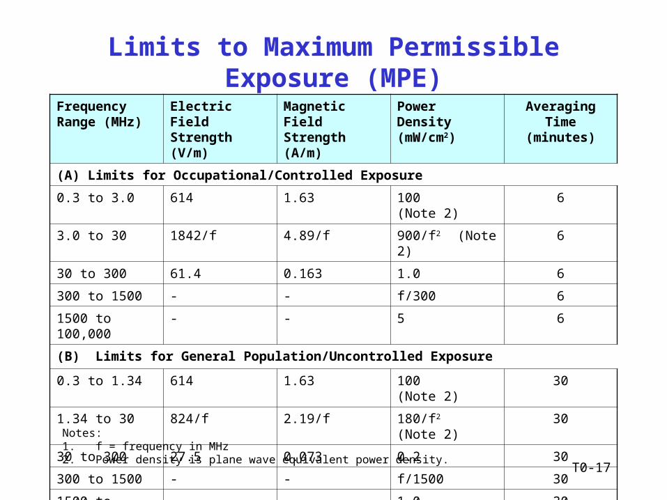
Limits to Maximum Permissible Exposure (MPE)
Frequency Range (MHz)
Electric Field Strength (V/m)
Magnetic Field Strength (A/m)
Power Density (mW/cm2)
Averaging Time (minutes)
(A) Limits for Occupational/Controlled Exposure
0.3 to 3.0 614 1.63 100 (Note 2) 6
3.0 to 30 1842/f 4.89/f 900/f2 (Note 2) 6
30 to 300 61.4 0.163 1.0 6
300 to 1500 - - f/300 6
1500 to 100,000 - - 5 6
(B) Limits for General Population/Uncontrolled Exposure
0.3 to 1.34 614 1.63 100 (Note 2) 30
1.34 to 30 824/f 2.19/f 180/f2 (Note 2) 30
30 to 300 27.5 0.073 0.2 30
300 to 1500 - - f/1500 30
1500 to 100,000 - - 1.0 30
Notes:1. f = frequency in MHz2. Power density is plane wave equivalent power density.

T0-18
MPE Power Density Limits
100 100
1 1
5 5
100 100
0.2 0.2
1 1
0.1
1
10
100
0.1 1 10 100 1000 10000 100000
Mhz
mW
/cm
2 Controlled
Uncontrolled
.3 to 3 3 to 30 30 to 300 300 to 1500 1500 to 100000
HF VHF UHF
T0-19
FCC RF Exposure Regulations
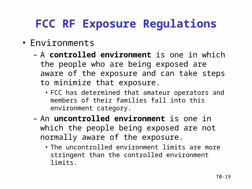
• Environments– A controlled environment is one in which the people
who are being exposed are aware of the exposure and can take steps to minimize that exposure.
• FCC has determined that amateur operators and members of their families fall into this environment category.
– An uncontrolled environment is one in which the people being exposed are not normally aware of the exposure.
• The uncontrolled environment limits are more stringent than the controlled environment limits.
T0-20
FCC RF Exposure Regulations
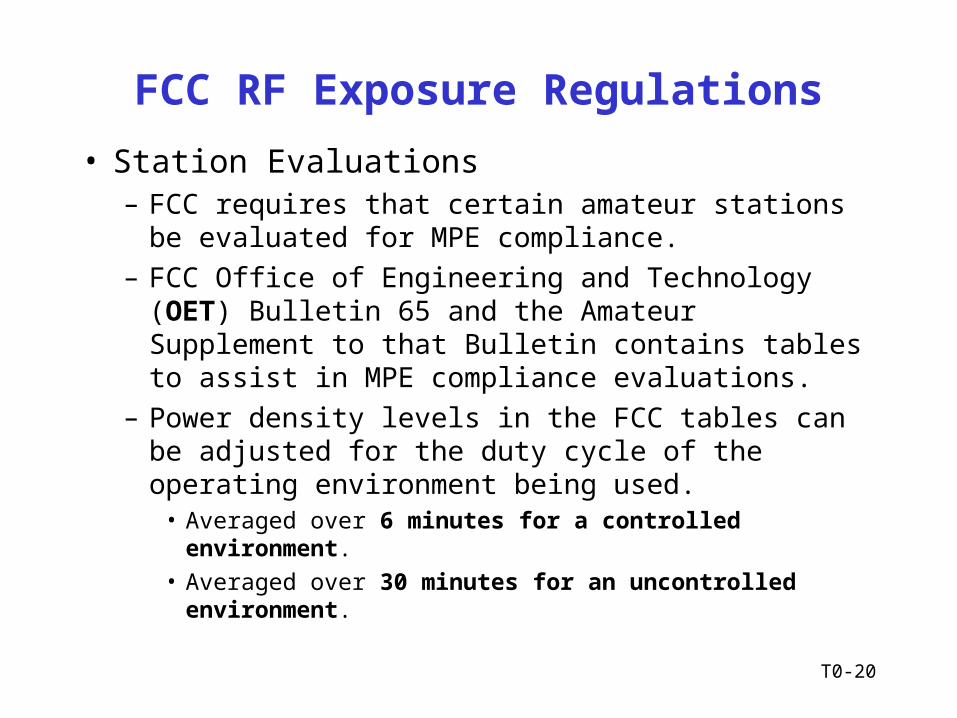
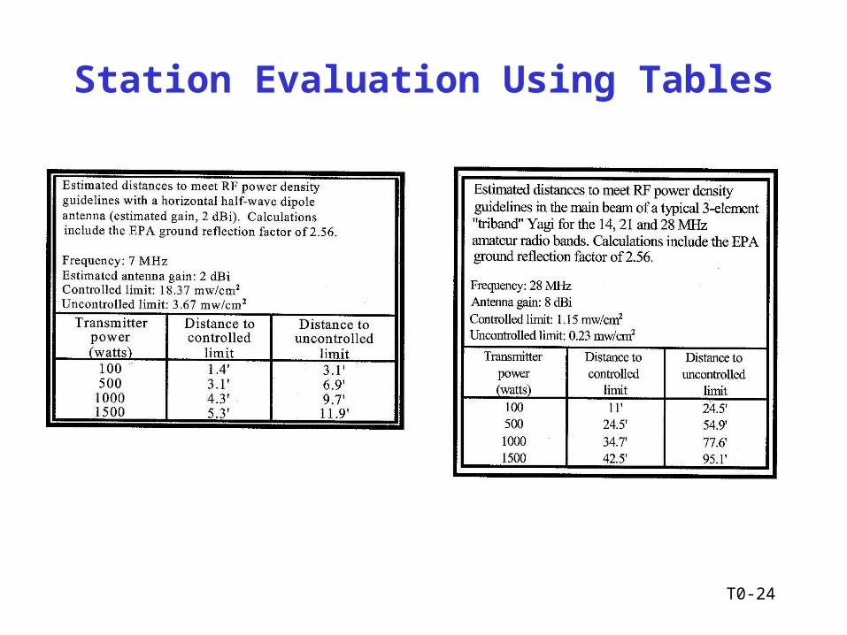
• Station Evaluations– FCC requires that certain amateur stations be evaluated
for MPE compliance.
– FCC Office of Engineering and Technology (OET) Bulletin 65 and the Amateur Supplement to that Bulletin contains tables to assist in MPE compliance evaluations.
– Power density levels in the FCC tables can be adjusted for the duty cycle of the operating environment being used.
• Averaged over 6 minutes for a controlled environment.
• Averaged over 30 minutes for an uncontrolled environment.
T0-21
FCC RF Exposure Regulations
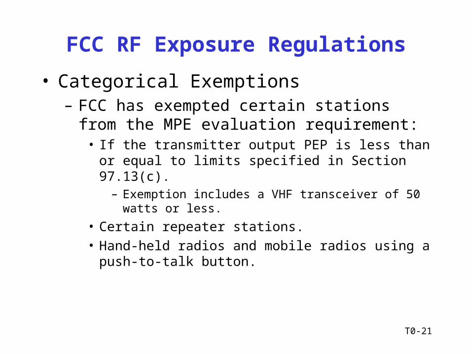
• Categorical Exemptions– FCC has exempted certain stations from the MPE
evaluation requirement:• If the transmitter output PEP is less than or equal to limits
specified in Section 97.13(c).– Exemption includes a VHF transceiver of 50 watts or less.
• Certain repeater stations.
• Hand-held radios and mobile radios using a push-to-talk button.

T0-22
Power Thresholds for Routine Evaluations
Wavelength
Band
Evaluation Required if
Power* (watts) Exceeds
160m 500
80 m 500
75 m 500
40 m 500
30 m 425
20 m 225
17 m 125
15 m 100
12 m 75
10 m 50
VHF (all bands) 50
* Transmitter power = Peak-envelope power input to antenna.
97.13(c)
T0-23
Routine Station Evaluations
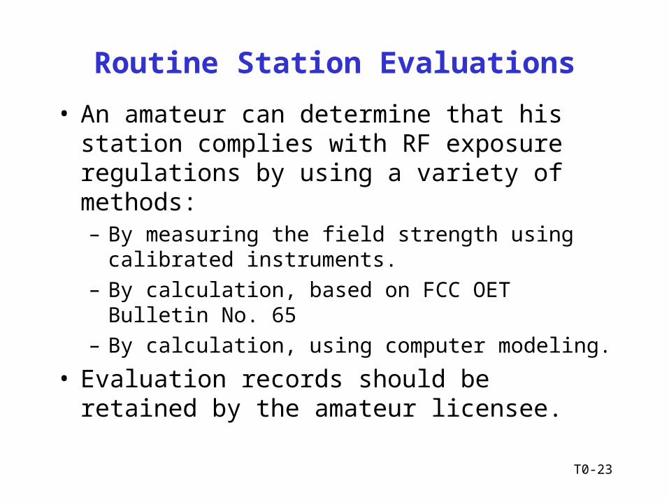
• An amateur can determine that his station complies with RF exposure regulations by using a variety of methods:– By measuring the field strength using calibrated
instruments.
– By calculation, based on FCC OET Bulletin No. 65
– By calculation, using computer modeling.
• Evaluation records should be retained by the amateur licensee.
T0-24
Station Evaluation Using Tables
T0-25
Field Strengths Around Your Antenna
• Field strengths around an antenna can be determined by direct measurement, using calibrated instruments, or by calculations using either tables or computer software.
• For analysis purposes, the area around an antenna is divided into the following regions:– Reactive near field
• Considered to be within a half wavelength of antenna
– Radiating near field• Field strength varies as inverse square of distance
– Radiating far field

T0-26
Field Strengths Around Your Antenna
Far Radiating Field
L
λ
2L2
DipoleAntenna
Near Radiating Field
ReactiveField
T0-27
Limiting RF Exposure
• Reduce transmitter power• Raise your antenna higher in the air and farther
away from your neighbor’s property line– Half-wavelength dipole antennas generally generate a
stronger RF field directly under the antenna that other types of antennas.
• Do not aim your antenna in a direction where people are likely to be located.
• Select an operating frequency with a higher MPE limit.
T0-28
Limiting RF Exposure (Cont’d)
• Use an emission with a lower duty cycle.– Single side-band (SSB) generally produces the lowest
duty cycle.
• Reduce your actual transmitting time– In a controlled environment, the RF exposure is
averaged over any 6 minute period.
– In a non-controlled environment, the RF exposure is average over any 30 minute period.
Recommended
![SUBELEMENT T10 Electrical safety: AC and DC power circuits; antenna installation; RF hazards [3 Exam Questions - 3 Groups] 1Electrical Safety 2014](https://img.pdfslide.net/doc/110x75/56649ec05503460f94bcb5b8/subelement-t10-electrical-safety-ac-and-dc-power-circuits-antenna-installation.jpg)