3-1© 2012 Schneider ElectricAll Rights Reserved
3M
OL
DE
D C
AS
E C
IRC
UIT
B
RE
AK
ER
S
Table of Contents
Section 3Molded Case Circuit Breakers and Enclosures
PowerPact™ Circuit Breakers 3-3
PowerPact™ H- and J-Frame Circuit Breakers 3-2–3-3
PowerPact™ L-Frame Circuit Breakers 3-4
PowerPact™ D-Frame Circuit Breakers 3-5
PowerPact™ Automatic Switches 3-6
PowerPact™ D-frame Mission Critical Circuit Breakers 3-6
Molded Case Circuit Breakers 3-7
F-Frame Thermal-Magnetic Circuit Breakers 3-7—3-8
K- and Q4-Frame Thermal-Magnetic Circuit Breakers 3-9—3-10
L-Frame Thermal-Magnetic Circuit Breakers 3-11—3-12
L-Frame Micrologic™ Series B Trip Circuit Breakers 3-13—3-14
Mag-Gard™ Motor Circuit Protector 3-15
GJ-Frame MCP Selection 3-16
Special Construction Circuit Breakers 3-17
Special Terminal Connectors and Lugs 3-17
Special Calibration, Rear-Connected Studs, Visi-Blade, Moisture/Fungus Treatment, and Short LA/LH Handle
3-18
Special Calibration, Rear-Connected Studs, Visi-Blade, Moisture/Fungus Treatment, and Short LA/LH Handle
3-18
P-Frame Replacement Handles, Key Interlock Adapter Plate and Exchange Program
3-19
Special Terminations 3-20
Grounded BØ Systems 3-21
UL Marine Listed Circuit Breakers 3-22
Circuit Breaker Accessories 3-23
PowerPact™ Circuit Breakers Electrical Accessories 3-23
Factory-Installed Accessories 3-24
Field-Installable Accessories 3-25
Electrical Operators, Handle Accessories, Cylinder Locks, and Walking Beam Mechanical Interlocks
3-26
Locks, Installation Accessories, and Rear Connections 3-27
Mechanical Lug Information 3-28
Compression Lug and Power Distribution Connectors 3-29
PowerPact™ Circuit Breakers Miscellaneous Accessories 3-30
Electronic Products 3-31
Neutral Current Transformers and Micrologic™ Series B Trip Unit Accessories
3-31
Restraint Interface Module 3-32
Circuit Breaker Dimensions 3-33
Enclosures 3-34
Industrial Circuit Breaker Enclosures 3-34
Enclosed Switches and Enclosure Dimensions 3-35
Accessories 3-36
Key Interlock Systems—Factory Installed Only 3-37
Special Applications 3-38

3M
OLD
ED
CA
SE
CIR
CU
IT
BR
EA
KE
RS
PowerPact™ Circuit Breakers
PowerPact™ H- and J-Frame Circuit BreakersClass 611 / Refer to Catalog 0611CT1001
www.schneider-electric.us
a To complete catalog number, replace the blank with the appropriate rating (D, G, J, L)b For 80% rated use “T” or for 100% rated Use “R” in the 9th character place (for example, HDL36015T or HDL36015R). 100% rated H- and J-frame circuit
breakers have copper lugs and can only be used with copper wire.c Circuit breakers will be labeled with Line and Load markings and are not suitable for reverse connections.
Only available on standard (80%) rated 3P unit-mount circuit breakers; not available with I-Line™ or Plug-In constructions.
d See Digest page 7-39–3-41 for lug and termination kits.e J and L interrupts are UL Certified as current limiting.
Accessories . . . . . . . . . . . . . . . . . . . . . . . . . . . . . . . . . . . . . Digest Page 7-35Optional Lugs . . . . . . . . . . . . . . . . . . . . . . . . . . . . . . . . . . . . Digest Page 7-38Dimensions . . . . . . . . . . . . . . . . . . . . . . . . . . . . . . . . . . . . . Digest Page 7-53Enclosures . . . . . . . . . . . . . . . . . . . . . . . . . . . . . . . . . . . . . . Digest Page 7-54
Table 3.1: H-Frame 150 A UL Current-Limitinge Circuit Breaker Frame with Field-Interchangeable Thermal-Magnetic Trip Unitsc (600 Vac, 250 Vdc)
AmpereRating
Fixed AC Magnetic Trip Cat.
No.b
D Interrupting G Interrupting Je Interrupting Le Interrupting Terminal
Wire Range Hold Trip
$ Price
80% Rated 100% Rated 80% Rated 100% Rated 80% Rated 100% Rated 80% Rated 100% Rated3P, 600 Vac 50/60 Hz
15 A 350 A 750 A H(a)L36015( ) 1088.00 1305.00 1493.00 1791.00 1949.00 2339.00 2849.00 3419.00
AL150HD14–3/0 AWG
Al or Cu
20 A 350 A 750 A H(a)L36020( ) 1088.00 1305.00 1493.00 1791.00 1949.00 2339.00 2849.00 3419.0025 A 350 A 750 A H(a)L36025( ) 1088.00 1305.00 1493.00 1791.00 1949.00 2339.00 2849.00 3419.0030 A 350 A 750 A H(a)L36030( ) 1088.00 1305.00 1493.00 1791.00 1949.00 2339.00 2849.00 3419.0035 A 400 A 850 A H(a)L36035( ) 1088.00 1305.00 1493.00 1791.00 1949.00 2339.00 2849.00 3419.0040 A 400 A 850 A H(a)L36040( ) 1088.00 1305.00 1493.00 1791.00 1949.00 2339.00 2849.00 3419.0045 A 400 A 850 A H(a)L36045( ) 1088.00 1305.00 1493.00 1791.00 1949.00 2339.00 2849.00 3419.0050 A 400 A 850 A H(a)L36050( ) 1088.00 1305.00 1493.00 1791.00 1949.00 2339.00 2849.00 3419.0060 A 800 A 1450 A H(a)L36060( ) 1088.00 1305.00 1493.00 1791.00 1949.00 2339.00 2849.00 3419.0070 A 800 A 1450 A H(a)L36070( ) 1328.00 1592.00 1701.00 2042.00 2099.00 2519.00 3149.00 3779.0080 A 800 A 1450 A H(a)L36080( ) 1328.00 1592.00 1701.00 2042.00 2099.00 2519.00 3149.00 3779.0090 A 800 A 1450 A H(a)L36090( ) 1328.00 1592.00 1701.00 2042.00 2099.00 2519.00 3149.00 3779.00100 A 900 A 1700 A H(a)L36100( ) 1328.00 1592.00 1701.00 2042.00 2099.00 2519.00 3149.00 3779.00110 A 900 A 1700 A H(a)L36110( ) 2600.00 3120.00 3599.00 4319.00 5174.00 6209.00 6749.00 8099.00125 A 900 A 1700 A H(a)L36125( ) 2600.00 3120.00 3599.00 4319.00 5174.00 6209.00 6749.00 8099.00150 A 900 A 1700 A H(a)L36150( ) 2600.00 3120.00 3599.00 4319.00 5174.00 6209.00 6749.00 8099.00
Table 3.2: J-Frame 250 A UL Current-Limitinge Circuit Breaker Frame with Field-Interchangeable Thermal-Magnetic Trip Unitsc (600 Vac, 250 Vdc)
AmpereRating
Adjustable AC Magnetic Trip Cat.
No.b
D Interrupting G Interrupting Je Interrupting Le Interrupting Terminal
Wire Range$ Price
Low High 80% Rated 100% Rated 80% Rated 100% Rated 80% Rated 100% Rated 80% Rated 100% Rated3P, 600 Vac 50/60 Hz
150 A 750 A 1500 A J(a)L36150( ) 2730.00 3276.00 3779.00 4535.00 5432.00 6519.00 7086.00 8504.00 AL175JD4--4/0 AWG Al or Cu175 A 875 A 1750 A J(a)L36175( ) 2730.00 3276.00 3779.00 4535.00 5432.00 6519.00 7086.00 8504.00
200 A 1000 A 2000 A J(a)L36200( ) 2730.00 3276.00 3779.00 4535.00 5432.00 6519.00 7086.00 8504.00 AL250JD3/0 AWG–350 kcmil Al
or Cu225 A 1125 A 2250 A J(a)L36225( ) 2730.00 3276.00 3779.00 4535.00 5432.00 6519.00 7086.00 8504.00250 A 1250 A 2500 A J(a)L36250( ) 3749.00 4499.00 5001.00 6002.00 7238.00 8685.00 8993.00 10791.00
Table 3.3: H-Frame 150A and J-Frame 250 A 3P Basic UL Current-Limitinge Circuit Breaker Frame Without Terminationsd or Trip Unit (600 Vac, 250 Vdc)
Circuit Breaker Frame
AmpereRating
D Interrupting G Interrupting Je Interrupting Le Interrupting
Cat. No. $ Price Cat. No. $ Price Cat. No. $ Price Cat. No. $ Price
H-Frame15–60 A HDF36000F06 525.00 HGF36000F06 930.00 HJF36000F06 1386.00 HLF36000F06 2286.0070–150 A HDF36000F15 585.00 HGF36000F15 1574.00 HJF36000F15 3149.00 HLF36000F15 4724.00
J-Frame 150–250 A JDF36000F25 1538.00 JGF36000F25 2790.00 JJF36000F25 5027.00 JLF36000F25 6782.00
Table 3.4: H-Frame and J-Frame 3P Field-Installable Thermal-Magnetic Trip Unit 15–60 A H-Frame 70–150 A H-Frame 150–250 A J-Frame
Amperage Cat. No. $ Price Amperage Cat. No. $ Price Amperage Cat. No. $ Price 15 A HT3015 563.00 70 A HT3070 743.00 150 A JT3150 1193.0020 A HT3020 563.00 80 A HT3080 743.00 175 A JT3175 1193.0025 A HT3025 563.00 90 A HT3090 743.00 200 A JT3200 1193.0030 A HT3030 563.00 100 A HT3100 743.00 225 A JT3225 1193.0035 A HT3035 563.00 110 A HT3110 2025.00 250 A JT3250 2213.0040 A HT3040 563.00 125 A HT3125 2025.00 — — — 45 A HT3045 563.00 150 A HT3150 2025.00 — — — 50 A HT3050 563.00 — — — — — — 60 A HT3060 563.00 — — — — — —
Table 3.5: H- and J-Frame Interrupting Ratings
VoltageInterrupting Rating
D G J L240 Vac 25 KA 65 kA 100 kA 125 kA480 Vac 18 kA 35 kA 65 kA 100 kA600 Vac 14 kA 18 kA 25 kA 50 kA
Table 3.6: H- and J-Frame Termination OptionsTermination Letter
A - I-Line (See Section 9)F = No Lugs (includes terminal nut kit on both ends)fL = Lugs both endsM = Lugs ON end Terminal Nut Kit OFF endP = Lugs OFF end Terminal Nut Kit ON endN = Plug-in gD = Drawout gS = Rear Connected gf Add TS suffix for circuit breaker without terminal nut kit.g For N and D pricing, add termination pricing on Digest page 7-41 to price. For S pricing, add termination pricing
on Digest page 7-37 to price.
H-Frame Trip Unit
H D L 3 6 0 1 5 T
For factory-installed termination, place termination letter in the third block of the circuit breaker catalog number.
Termination Letter
3-2 © 2012 Schneider ElectricAll Rights Reserved
DE2 Discount Schedule

© 2012 Schneider ElectricAll Rights Reserved
PowerPact™ Circuit Breakers
PowerPact™ H- and J-Frame Circuit BreakersClass 611 / Refer to Catalog 0611CT1001
3M
OL
DE
D C
AS
E C
IRC
UIT
B
RE
AK
ER
S
www.schneider-electric.us
f See Digest page 7-38 for lug and termination kits.g J and L interrupts are UL Certified as current limiting.
Accessories . . . . . . . . . . . . . . . . . . . . . . . . . . . . . . . . . . . . . Digest page 7-36Optional Lugs . . . . . . . . . . . . . . . . . . . . . . . . . . . . . . . . . . . . Digest page 7-39Dimensions . . . . . . . . . . . . . . . . . . . . . . . . . . . . . . . . . . . . . . Digest page 7-55Enclosures . . . . . . . . . . . . . . . . . . . . . . . . . . . . . . . . . . . . . . Digest page 7-56
Table 3.7: H-Frame 150 A and J-Frame 250 A Circuit Breakers with Lugs and Field-Interchangeable Electronic Trip Units cd(600 Vac, 50/60 Hz, 3P) cd
Electronic Trip Unit
SensorRating
Cat.No.b
Interrupting Rating (2nd Letter of Catalog Number)
Terminal Wire Range Type Function Trip
Unit
D Interrupting G Interrupting J Interrupting L Interrupting
$ Price
80% Rated 100% Rated 80% Rated 100% Rated 80% Rated 100% Rated 80% Rated 100% Rated
Micrologic Standard LI 3.2
60 A100 A150 A
H(a)L36060( )U31XH(a)L36100( )U31XH(a)L36150( )U31X
1247.001487.002759.00
1455.001735.003220.00
1652.001860.003758.00
1928.002171.004386.00
2108.002258.005333.00
2460.002635.006224.00
3008.003308.006908.00
3510.003860.008062.00
AL150HD14–3/0 AWG Al or Cu
250 A J(a)L36250( )U31X 2957.00 3451.00 4006.00 4675.00 5659.00 6604.00 7313.00 8534.00 AL250JD3/0 AWG–350 kcmil Al or Cue
Micrologic Standard LSI 3.2S
60 A100 A150 A
H(a)L36060( )U33XH(a)L36100( )U33XH(a)L36150( )U33X
1433.001673.002945.00
1641.001921.003405.00
1838.002046.003944.00
2113.002356.004571.00
2294.002444.005519.00
2646.002821.006409.00
3194.003494.007094.00
3696.004046.008247.00
AL150HD14–3/0 AWG Al or Cu
250 A J(a)L36250( )U33X 3221.00 3715.00 4270.00 4939.00 5923.00 6868.00 7577.00 8798.00 AL250JD3/0 AWG–350 kcmil Al or Cue
Micrologic Ammeter LSI 5.2A
60 A100 A150 A
H(a)L36060( )U43XH(a)L36100( )U43XH(a)L36150( )U43X
2031.002271.003543.00
2240.002520.004004.00
2436.002644.004542.00
2712.002955.005170.00
2892.003042.006117.00
3244.003419.007008.00
3792.004092.007692.00
4295.004645.008846.00
AL150HD14–3/0 AWG Al or Cu
250 A J(a)L36250( )U43X 4075.00 4569.00 5124.00 5793.00 6777.00 7722.00 8431.00 9653.00 AL250JD3/0 AWG–350 kcmil Al or Cue
Micrologic Energy LSI 5.2E
60 A100 A150 A
H(a)L36060( )U53XH(a)L36100( )U53XH(a)L36150( )U53X
2391.002631.003903.00
2599.002879.004363.00
2796.003004.004902.00
3072.003314.005529.00
3252.003402.006477.00
3604.003779.007367.00
4152.004458.008052.00
4654.005004.009205.00
AL150HD14–3/0 AWG Al or Cu
250 A J(a)L36250( )U53X 4588.00 5082.00 5637.00 6306.00 7290.00 8235.00 8944.00 10165.00 AL250JD3/0 AWG–350 kcmil Al or Cue
Micrologic Ammeter LSIG 6.2A
60 A100 A150 A
H(a)L36060( )U44XH(a)L36100( )U44XH(a)L361504( )U44X
2751.002991.004263.00
2960.003240.004724.00
3156.003364.005262.00
3432.003675.005890.00
3612.003762.006837.00
3964.004139.007728.00
4512.004812.008412.00
5015.005365.009566.00
AL150HD14–3/0 AWG Al or Cu
250 A J(a)L36250( )U44X 5100.00 5594.00 6149.00 6818.00 7802.00 8747.00 9456.00 10678.00 AL250JD3/0 AWG–350 kcmil Al or Cue
Micrologic Energy LSIG 6.2E
60 A100 A150 A
H(a)L36060( )U54XH(a)L36100( )U54XH(a)L36150( )U54X
3111.003351.004623.00
3319.003599.005083.00
3516.003724.005622.00
3792.004034.006249.00
3972.004122.007197.00
4324.004499.008087.00
4872.005172.008772.00
5374.005724.009925.00
AL150HD14–3/0 AWG Al or Cu
250 A J(a)L36250( )U54X 5613.00 6107.00 6662.00 7331.00 8315.00 9260.00 9969.00 11190.00 AL250JD3/0 AWG–350 kcmil Al or Cue
a To complete catalog number, replace the blank with the appropriate rating (D, G, J, L)b For 80% rated use “T” or for 100% rated Use “R” in the 9th character place (for example, HGL36015TU31X or HGL36015RU31X). 100% rated H- and J-frame circuit breakers have copper
lugs and can only be used with copper wire.c Circuit breakers will be labeled with Line and Load markings and are not suitable for reverse connections.d Only available on 3P unit-mount circuit breakers. Not available with I-Line™ or Plug-in constructions.e For smaller wire (4–4/0 AWG Al or Cu), replace the lug wire binding screws with longer binding screws provided.
Table 3.8: H-Frame 150A and J-Frame 250 A 3P Basic UL Current-Limitingg Circuit Breaker Frame Without Terminationsf or Trip Unit (600 Vac, 250 Vdc)
Circuit Breaker Frame
AmpereRating
D Interrupting G Interrupting Jg Interrupting Lg Interrupting
Cat. No. $ Price Cat. No. $ Price Cat. No. $ Price Cat. No. $ Price
H-Frame15–60 A HDF36000F06 525.00 HGF36000F06 930.00 HJF36000F06 1386.00 HLF36000F06 2286.0070–150 A HDF36000F15 585.00 HGF36000F15 1574.00 HJF36000F15 3149.00 HLF36000F15 4724.00
J-Frame 150–250 A JDF36000F25 1538.00 JGF36000F25 2790.00 JJF36000F25 5027.00 JLF36000F25 6782.00
Table 3.9: Micrologic Field-Installable Trip Unit
Model Trip Function
Trip Unit Contiuous Current Trip Unit
Cat. No. $ Price Termination Letter
Micrologic Standard
LI 3.2
15-20-25-30-35-40-45-50-60 HE3060U31X 722.00 A - I-Line (See Section 9)35-40-45-50-60-70-80-90-100 HE3100U31X 902.00 F = No Lugs (includes terminal nut kit on both ends)h50-60-70-80-90-100-110-125-150 HE3150U31X 2184.00 L = Lugs both ends70-80-100-125-150-175-200-225-250 JE3250U31X 1216.00 M = Lugs ON end Terminal Nut Kit OFF end
LSI 3.2S
15-20-25-30-35-40-45-50-60 HE3060U33X 908.00 P = Lugs OFF end Terminal Nut Kit ON end35-40-45-50-60-70-80-90-100 HE3100U33X 1088.00 N = Plug-in i50-60-70-80-90-100-110-125-150 HE3150U33X 2370.00 D = Drawout i70-80-100-125-150-175-200-225-250 JE3250U33X 1480.00 S = Rear Connected i
Micrologic Ammeter
LSI 5.2A
15–60 HE3060U43X 1506.0035–100 HE3100U43X 1686.0050–150 HE3150U43X 2968.0070–250 JE3250U43X 2334.00
LSIG 6.2A
15–60 HE3060U44X 1866.0035–100 HE3100U44X 2046.0050–150 HE3150U44X 3318.00 h Add TS suffix for circuit breaker without
terminal nut kit.i For N and D pricing, add termination pricing on
Digest page 7-42 to price. For S pricing, add termination pricing on Digest page 7-38 to price.
70–250 JE3250U44X 2847.00
Micrologic Energy
LSI 5.2E
15–60 HE3060U53X 2226.0035–100 HE3100U53X 2406.0050–150 HE3150U53X 4038.0070–250 JE3250U53X 3359.00
LSIG 6.2E
15–60 HE3060U54X 2586.0035–100 HE3100U54X 2766.0050–150 HE3150U54X 4038.0070–250 JE3250U54X 3872.00
Table 3.10: H- and J-Frame Interrupting Ratings
VoltageInterrupting Rating
D G J L240 Vac 25 KA 65 kA 100 kA 125 kA480 Vac 18 kA 35 kA 65 kA 100 kA600 Vac 14 kA 18 kA 25 kA 50 kA
H D L 3 6 0 1 5 T
For factory-installed termination, place termination letter in the third block of the circuit breaker catalog number.
3-3
DE2 Discount Schedule
3M
OLD
ED
CA
SE
CIR
CU
IT
BR
EA
KE
RS
PowerPact™ Circuit Breakers
PowerPact™ L-Frame Circuit BreakersClass 612, 615 / Refer to Catalogs: 0612CT0101, 0616CT0801
www.schneider-electric.us
e For N, D, and S pricing, add termination pricing to price. See Digest page 7-42.
Accessories . . . . . . . . . . . . . . . . . . . . . . . . . . . . . . .Digest pages 7-36–7-45Optional Lugs . . . . . . . . . . . . . . . . . . . . . . . . . . . . . .Digest pages 7-39–7-40Dimensions. . . . . . . . . . . . . . . . . . . . . . . . . . . . . . . . . . . . . . Digest page 7-55
Table 3.11: L-Frame 3 Pole, 600 A Circuit Breakers with Lugs and Field-Interchangeable Electronic Trip Units (600 Vac, 50/60 Hz)ad
Electronic Trip Unit SensorRating
Cat.No.b
D Interrupting G Interrupting J Interrupting L Interrupting
Terminal Wire Range
$ Price
Type Function Trip Unit 80% Rated 100% Rated 80% Rated 100% Rated 80% Rated 100% Rated 80% Rated 100% Rated
Micrologic Standard LI 3.3
250 A L(a)L36250( )U31 4287.00 5648.00 5081.00 5945.00 8487.00 9919.00 9918.00 11604.00AL400L61K3D
(1) 2 AWG–600 kcmil Cu(1) 2 AWG–500 kcmil Al
400 A600 A
L(a)L36400( )U31XL(a)L36600( )U31X
4827.007109.00
5648.00—
5081.007484.00
5945.00—
8487.0010541.00
9919.00—
9918.0011837.00
11604.00—
AL600S52K3(2) 2/0 AWG–500 kcmil Al/Cu
Micrologic Standard LSI 3.3S
250 A L(a)L36250( )U33X 5391.00 6211.00 5674.00 6538.00 9071.00 10513.00 10511.00 12198.00AL400L61K3D
(1) 2 AWG–600 kcmil Cu(1) 2 AWG–500 kcmil Al
400 A600 A
L(a)L36400( )U33XL(a)L36600( )U33X
5391.007673.00
6211.00—
5674.008077.00
6538.00—
9071.0011134.00
10513.00—
10511.0012430.00
12198.00—
AL600S52K3(2) 2/0 AWG–500 kcmil Al/Cu
Micrologic Ammeter LSI 5.3A 400 A
600 AL(a)L36400( )U43XL(a)L36600( )U43X
6253.008535.00
7073.00—
6582.008984.00
7445.00—
9979.0012041.00
11420.00—
11419.0013337.00
13105.00—
AL600S52K3(2) 2/0 AWG–500 kcmil Al/Cu
Micrologic Energy LSI 5.3E 400 A
600 AL(a)L36400( )U53XL(a)L36600( )U53X
7200.009483.00
8021.00—
7579.009982.00
8443.00—
10976.0013039.00
12418.00—
12416.0014335.00
14103.00—
Micrologic Ammeter LSIG 6.3A 400 A
600 AL(a)L36400( )U44XL(a)L36600( )U44X
8149.0010431.00
8969.00—
8578.0010980.00
9441.00—
11975.0014037.00
13416.00—
13415.0015333.00
15101.00—
Micrologic Energy LSIG 6.3E 400 A
600 AL(a)L36400( )U54XL(a)L36600( )U54X
9097.0011379.00
9917.00—
9575.0011978.00
10439.00—
12972.0015035.00
14414.00—
14412.0016331.00
16099.00—
a To complete catalog number, replace the blank with the appropriate rating (D, G, J, L)b For 80% rated use “T” or for 100% rated Use “R” in the 9th character place (for example, LGL36400TU31X or LGL36400RU31X). 100% rated H- and J-frame circuit breakers have copper
lugs and can only be used with copper wire.c Circuit breakers will be labeled with Line and Load markings and are not suitable for reverse connections.d Only available on 3P unit-mount circuit breakers.
Table 3.12: L-Frame 3 Pole, 600 A Circuit Breaker Breaker Frame without Trip Units (600 Vac, 50/60 Hz)
AmpereRating
D Interrupting G Interrupting J Interrupting L Interrupting
Cat. No. $ Price Cat. No. $ Price Cat. No. $ Price Cat. No. $ Price
250 A (70–250 A) LDF36000F25 1328.00 LGF36000F25 1480.00 LJF36000F25 4616.00 LLF36000F25 6069.00400 A (125–400 A LDF36000F40 2628.00 LGF36000F40 2766.00 LJF36000F40 6164.00 LLF36000F40 7602.00600 A (200–600 A) LDF36000F60 5199.00 LGF36000F60 5472.00 LJF36000F60 8226.00 LLF36000F60 9522.00
Table 3.13: L-Frame 3P Field-Installable Micrologic Electronic Trip Units Electronic Trip Unit
Continuous Current Trip Unit Cat. No. $ Price
Type Function Code
Micrologic Standard
LI 3.370-80-100-125-150-175-200-225-250 LE3250U31X 2315.00125-150-175-200-225-250-300-350-400 LE3400U31X 2315.00200-225-250-300-350-400-450-500-600 LE3600U31X 2315.00
LSI 3.3S70-80-100-125-150-175-200-225-250 LE3250U33X 2908.00125-150-175-200-225-250-300-350-400 LE3400U33X 2908.00200-225-250-300-350-400-450-500-600 LE3600U33X 2908.00
Micrologic Ammeter
LSI 5.3A125–400 LE3400U43X 3816.00200–600 LE3600U43X 3816.00
LSIG 6.3A125–400 LE3400U44X 4813.00200–600 LE3600U44X 4813.00
Micrologic EnergyLSI 5.3E
125–400 LE3400U53X 5812.00200–600 LE3600U53X 5812.00
LSIG 6.3E125–400 LE3400U54X 6809.00200–600 LE3600U54X 6809.00
Table 3.14: Termination OptionsTermination Letter Termination Option
A I-Line (See Section 9)F No lugs (includes terminal nut kit on both ends) L Lugs both endsM Lugs ON end, terminal nut kit OFF endP Lugs OFF end, terminal nut kit ON end
Ne Plug InDe DrawoutSe Rear Connected
M G L 3 6 4 0 0 or
For factory-installed termination, place termination letter in the third block of the circuit breaker catalog number.
Termination Letter
L G L 3 6 6 0 0 U 4 4 X
Table 3.15: L-Frame Interrupting Ratings
VoltageInterrupting Rating
D G J L
240 Vac 25 kA 65 kA 100 kA 125 kA480 Vac 18 kA 35 kA 65 kA 100 kA600 Vac 14 kA 18 kA 25 kA 50 kA
3-4 © 2012 Schneider ElectricAll Rights Reserved
DE2 Discount Schedule

© 2012 Schneider ElectricAll Rights Reserved
PowerPact™ Circuit Breakers
PowerPact™ D-Frame Circuit BreakersClass 612, 615 / Refer to Catalogs: 0612CT0101, 0616CT0801
3M
OL
DE
D C
AS
E C
IRC
UIT
B
RE
AK
ER
S
www.schneider-electric.us
a Price shown is for quantity of 1.
b For N, D, and S pricing, add termination pricing to price.
Accessories . . . . . . . . . . . . . . . . . . . . . . . . . . . . . . . . . . . . . Page 3-24—3-27Optional Lugs . . . . . . . . . . . . . . . . . . . . . . . . . . . . . . . . . . . . Page 3-28—3-29Dimensions . . . . . . . . . . . . . . . . . . . . . . . . . . . . . . . . . . . . . . . . . . . .Page 3-33Enclosures. . . . . . . . . . . . . . . . . . . . . . . . . . . . . . . . . . . . . . .Digest Page 7-56
Table 3.16: D-Frame (600 A 600 Vac) 3P 50/60 Hz Circuit Breaker with Lugs and Electronic Trip Unitsa
Electronic Trip Unit Type Trip Function Trip Unit Continuous
CurrentG Interrupting J Interrupting L Interrupting Terminal Wire Range
(AWG/kcmil)Cat. No. $ Price Cat. No. $ Price Cat. No. $ Price
Standard
LS STR23SP
150 A DGL36150E20 5081.00 DJL36150E20 8478.00 DLL36150E20 9918.00(1) 2–600 Cu or (1) 2–500 Al250 A DGL36250E20 5081.00 DJL36250E20 8478.00 DLL36250E20 9918.00
400 A DGL36400E20 5081.00 DJL36400E20 8478.00 DLL36400E20 9918.00600 A DGL36600E20 8315.00 DJL36600E20 11712.00 DLL36600E20 13152.00 (2) 2/0–350 Cu or (2) 2/0–500 Al
LSI SR53UP-Fb
150 A DGL36150E53 6200.00 DJL36150E53 9597.00 DLL36150E53 11037.00(1) 2–600 Cu or (1) 2–500 Al250 A DGL36250E53 6200.00 DJL36250E53 9597.00 DLL36250E53 11037.00
400 A DGL36400E53 6200.00 DJL36400E53 9597.00 DLL36400E53 11037.00600 A DGL36600E53 9429.00 DJL36600E53 12813.00 DLL36600E53 14721.00 (2) 2/0–350 Cu or (2) 2/0–500 Al
LSIG STR53UP-FTb
150 A DGL36150E54 7527.00 DJL36150E54 10925.00 DLL36150E54 12365.00(1) 2–600 Cu or (1) 2–500 Al250 A DGL36250E54 7527.00 DJL36250E54 10925.00 DLL36250E54 12365.00
400 A DGL36400E54 7527.00 DJL36400E54 10925.00 DLL36400E54 12365.00600 A DGL36600E54 10761.00 DJL36600E54 14159.00 DLL36600E54 15599.00 (2) 2/0–350 Cu or (2) 2/0–500 Al
Ammeter
LSI STR53UP-FIb
150 A DGL36150E58 7661.00 DJL36150E58 11058.00 DLL36150E58 12498.00(1) 2–600 Cu or (1) 2–500 Al250 A DGL36250E58 7661.00 DJL36250E58 11058.00 DLL36250E58 12498.00
400 A DGL36400E58 7661.00 DJL36400E58 11058.00 DLL36400E58 12498.00600 A DGL36600E58 10895.00 DJL36600E58 14292.00 DLL36600E58 15732.00 (2) 2/0–350 Cu or (2) 2/0–500 Al
LSIG STR53UP-FTIb
150 A DGL36150E59 8990.00 DJL36150E59 12387.00 DLL36150E59 13827.00(1) 2–600 Cu or (1) 2–500 Al250 A DGL36250E59 8990.00 DJL36250E59 12387.00 DLL36250E59 13827.00
400 A DGL36400E59 8990.00 DJL36400E59 12387.00 DLL36400E59 13827.00
600 A DGL36600E59 9434.00 DJL36600E59 15621.00 DLL36600E59 17061.00 (2) 2/0–350 Cu or (2) 2/0 –500 Al
a D-frame circuit breakers 400 A and below are 100% rated. 600 A is standard (80%) rated only.b F = Fault indicator; T = Residual-type ground-fault protection; I = Ammeterc Available with lugs (L) or bus (F) connections only.
Table 3.17: D-Frame 3P 600 A Circuit Breaker, Frame Only, and Field-Installable Trip Units Basic Frame Only (600 Vac)d Field Installable D-Frame Electronic Trip Unit
AmpereRating
G Interrupting J Interrupting L Interrupting Long-time, Short-time and Instantaneous Protection
Cat. No. $ Price Cat. No. $ Price Cat. No. $ Price Description Factory Code Trip Function Cat. No. $ Price
150 A DGL36150F40 2766.00 DJL36150F40 6164.00 DLL36150F40 7602.00 STR23SP E20 LS 36940 2033.00250 A DGL36250F40 2766.00 DJL36250F40 6164.00 DLL36250F60 7602.00 STR53UP-F E53 LSI 36942 3152.00400 A DGL36400F40 2766.00 DJL36400F40 6164.00 DLL36400F40 7602.00 STR53UP-FT E54 LSIG 36943 4479.00600 A DGL36600F60 5904.00 DJL36600F60 9302.00 DLL36600F60 10740.00 STR53UP-FI E58 LSI 36944 4613.00d Available with lugs (L) or bus (F) connections only. STR53UP-FTI E59 LSIG 36945 5942.00
Table 3.18: Plug-In and Drawout Mountings for D-Frame Circuit Breakers
Description Poles
Plug-in Mounting Drawout Mounting
FactoryInstalledCat. No.
Field-InstalledCat. No.
$ PriceFactoryInstalledCat. No.
Field-InstalledCat. No.
$ Price
Kit (stationary and moving parts)3 N 32546 1542.00 D 32548 2466.004 N M32547 2082.00 D M32549 3281.00
Stationary PartPlug-in base
3 32514 1065.00 32514 1065.004 M32515 1439.00 M32515 1439.00
Fixed part of chassis 32532 693.00
Moving Part
HJ00 710.00 HJ00 710.00Moving part of chassis 32533 231.00
Short terminal covers 3 32562 149.00 32562 149.004 32563 161.00 32563 161.00
Power connections3 3x 32518a 95.00 3x 32518a 95.004 4x 32518a 95.00 4x 32518a 95.00
Table 3.19: Plug-In and Drawout Accessories for D-Frame Circuit BreakersDescription Field-Installed Cat. No. $ Price
Secondary Disconnecting BlocksFixed Part 9-wire connector 29273 95.00
Moving Part9-wire connector 32523 60.00
Support for 3 moving connectors 32525 42.60Shutters Two shutters for plug-in base 32521 81.00
Chassis AccessoriesExtended escutcheon for toggle 32534 104.00Locking device (key lock is not included) 29286 164.00Two position indicating switches (connected/disconnected) 29287 207.00
Table 3.20: Termination Options
Frame Termination Letter Termination Option
D-Frame
F No Lugs (Includes terminal nut kit on both ends)L Lugs both endsM Lugs ON end Terminal Nut Kit Off endP Lugs OFF end Terminal Nut Kit On end
N b Plug-inD b DrawoutS b Rear Connected
M G L 3 6 4 0 0 or
For factory-installed termination, place termination letter in the third block of the circuit breaker catalog number.
Termination Letter
D G L 3 6 4 0 0 E 2 0
Table 3.21: D-Frame Interrupting Ratings
VoltageInterrupting Rating
G J L
240 Vac 65 kA 100 kA 125 kA480 Vac 35 kA 65 kA 100 kA600 Vac 18 kA 25 kA 25 kA
3-5
DE2 Discount Schedule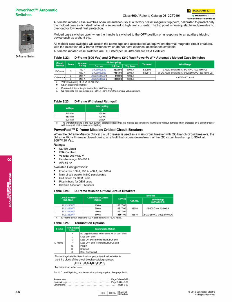
3M
OLD
ED
CA
SE
CIR
CU
IT
BR
EA
KE
RS
PowerPact™ Automatic Switches Class 600 / Refer to Catalog 0612CT0101
Automatic molded case switches open instantaneously at a factory preset magnetic trip point, ca
www.schneider-electric.uslibrated to protect only the molded case switch itself, when it is subjected to high fault currents. The trip point is nonadjustable and provides no overload or low level fault protection.
Molded case switches open when the handle is switched to the OFF position or in response to an auxiliary tripping device such as a shunt trip.
All molded case switches will accept the same lugs and accessories as equivalent thermal-magnetic circuit breakers, with the exception of Q-frame switches which do not have electrical accessories available.Automatic molded case switches are UL Listed per UL 489 and are CSA Certified.
c Withstand rating of 10 kA at 240 Vac.d DE2A discount schedule.
e P-frame L-interrupting is available in 480 Vac only.f UL magnetic trip tolerances are -20% / +30% from the nominal values shown.
g The withstand rating is the fault current at rated voltage that the molded case switch will withstand without damage when protected by a circuit breaker with an equal continuous current rating.
PowerPact™ D-frame Mission Critical Circuit BreakersWhen the D-frame Mission Critical circuit breaker is used as a main circuit breaker with QO branch circuit breakers, the D-frame MC will remain closed during any fault that occurs downstream of the QO circuit breaker up to 30kA at 208Y/120 Vac.Ratings:• UL 489 Listed• CSA Certified• Voltage: 208Y/120 V• Handle ratings: 60–600 A• AIR: 65 kA
Available Configurations:• Four sizes: 150 A, 250 A, 400 A, and 600 A• Main circuit breaker in NQ panelboards• Unit mount for OEM users• Plug-in base for OEM users• Drawout base for OEM users
a D-Frame circuit breakers 400 A and below are 100% rated.
For N, D, and S pricing, add termination pricing to price. See page 7-45
Accessories . . . . . . . . . . . . . . . . . . . . . . . . . . . . . . . . . . . . Page 3-24—3-27Optional Lugs . . . . . . . . . . . . . . . . . . . . . . . . . . . . . . . . . . . . Page 3-28—3-29Dimensions. . . . . . . . . . . . . . . . . . . . . . . . . . . . . . . . . . . . . . . . . . . . Page 3-33
Table 3.22: D-Frame (600 Vac) and Q-Frame (240 Vac) PowerPact™ Automatic Molded Case Switches
Circuit Breaker Poles Ampere
RatingJ Interrupting
Terminal Wire RangeCat. No. $ Price Trip Point
D-Frame 3400 A DJL36000S40 4572.00 6000 A S32508 2 AWG–500 kcmil Al or 2 AWG–600 kcmil Cu600 A DJL36000S60 7484.00 6000 A S32510 (2) 2/0 AWG–500 kcmil Al or (2) 2/0 AWG–350 kcmil Cu
Q-Framec2 225 A QBL22000S22d 440.00 4500 A
4 AWG–300 kcmil3 225 A QBL32000S22d 1193.00 4500 A
Table 3.23: D-Frame Withstand Ratingsg
VoltageInterrupting
J
240 Vac 150 kA480 Vac 100 kA600 Vac 25 kA
Table 3.24: D-Frame Mission Critical Circuit Breakers
Circuit BreakerCat. No.a
Continuous CurrentRating $ Price
Terminal
Cat. No. Wire Range(AWG/kcmil)
DJL32150W 150 A 10317.0032508 #2-600 Cu or #2-500 AlDJL32250W 250 A 10317.00
DJL32400W 400 A 10317.00DJL32600W 600 A 13551.00 32510 (2) 2/0-350 Cu or (2) 2/0-500Al
Table 3.25: Termination Options
Frame Termination Letter Termination Option
D-Frame
F No Lugs (Includes terminal nut kit on both ends)L Lugs both endsM Lugs ON end Terminal Nut Kit Off endP Lugs OFF end Terminal Nut Kit On endN Plug-inD DrawoutS Rear Connected
D-Frame Switch
For factory-installed termination, place termination letter in the third block of the circuit breaker catalog number.
Termination Letter
D G L 3 6 4 0 0 E 2 0
3-6 © 2012 Schneider ElectricAll Rights Reserved
DE2 DE2A Discount Schedule

© 2012 Schneider ElectricAll Rights Reserved
Molded Case Circuit Breakers
F-Frame Thermal-Magnetic Circuit BreakersClass 650
Thermal-magnetic molded case circuit breakers shown on
3M
OL
DE
D C
AS
E C
IRC
UIT
B
RE
AK
ER
S
www.schneider-electric.us
pages 3-7 through 3-18 are permanent trip UL Listed, CSA® Certified, IEC rated, and also meet the requirements of Federal Specification W–C–375B/GEN as indicated on Digest pages 7-4 through 7-7.
NOTE: Consider using PowerPact™ circuit breakers for situations requiring circuit breaker accessories. See Digest Section 7 for more information.
a See Section 11
Accessories . . . . . . . . . . . . . . . . . . . . . . . . . . . . . . . . . . . . . Page 3-24—3-27Optional Lugs . . . . . . . . . . . . . . . . . . . . . . . . . . . . . . . . . . . . Page 3-28—3-29Dimensions . . . . . . . . . . . . . . . . . . . . . . . . . . . . . . . . . . . . . . . . . . . .Page 3-33Enclosures: see Digest Section 7
FAL 1P 15–100 A
FAL/FHL 2P 15–100 A
FAL/FHL 3P 15–100 A
Table 3.26: F-Frame—100 A, Thermal-Magnetic, Individually-Mounted, Standard Interrupting, 240 Vac
AmpereRating
Fixed AC MagneticTrip
1 P 2 P 3 PTerminal Wire Range
(AWG)120 Vac 240 Vac 240 Vac
Hold Trip Cat. No. $ Price Cat. No. $ Price Cat. No. $ Price
15 A 275 A 600 A FAL12015 198.00 FAL22015 333.00 FAL32015 495.00
AL50FA14–4 Cu or 12–4 Al
20 A 275 A 600 A FAL12020 198.00 FAL22020 333.00 FAL32020 495.0025 A 275 A 600 A FAL12025 198.00 FAL22025 333.00 FAL32025 495.0030 A 275 A 600 A FAL12030 198.00 FAL22030 333.00 FAL32030 495.0035 A 400 A 850 A FAL12035 198.00 FAL22035 333.00 FAL32035 495.00
AL100FA14–1/0 Cu or 12–1/0 Al
40 A 400 A 850 A FAL12040 198.00 FAL22040 333.00 FAL32040 495.0045 A 400 A 850 A FAL12045 198.00 FAL22045 333.00 FAL32045 495.0050 A 400 A 850 A FAL12050 198.00 FAL22050 333.00 FAL32050 495.0060 A 800 A 1450 A FAL12060 198.00 FAL22060 333.00 FAL32060 495.0070 A 800 A 1450 A FAL12070 261.00 FAL22070 543.00 FAL32070 704.0080 A 800 A 1450 A FAL12080 261.00 FAL22080 543.00 FAL32080 704.0090 A 900 A 1700 A FAL12090 261.00 FAL22090 543.00 FAL32090 704.00100 A 900 A 1700 A FAL12100 261.00 FAL22100 543.00 FAL32100 704.00
Table 3.27: F-Frame—100 A, Thermal-Magnetic, Individually-Mounted, 480 Vac
Standard Interrupting
AmpereRating
Fixed AC MagneticTrip
1P 2P 3PTerminal
Wire Range(AWG)
277 Vac, 125 Vdc 480 Vac, 250 Vdc 480 Vac, 250 Vdc
Hold Trip Cat. No. $ Price Cat. No. $ Price Cat. No. $ Price
15 A 275 A 600 A FAL14015 251.00 FAL24015 609.00 FAL34015 782.00AL50FA
(1) 14–4 Cu or(1) 12–4 Al
20 A 275 A 600 A FAL14020 251.00 FAL24020 609.00 FAL34020 782.0025 A 275 A 600 A FAL14025 251.00 FAL24025 609.00 FAL34025 782.0030 A 275 A 600 A FAL14030 251.00 FAL24030 609.00 FAL34030 782.0035 A 400 A 850 A FAL14035 251.00 FAL24035 609.00 FAL34035 782.00
AL100FA(1) 14–1/0 Cu
or (1) 12–1/0 Al
40 A 400 A 850 A FAL14040 251.00 FAL24040 609.00 FAL34040 782.0045 A 400 A 850 A FAL14045 251.00 FAL24045 609.00 FAL34045 782.0050 A 400 A 850 A FAL14050 251.00 FAL24050 609.00 FAL34050 782.0060 A 800 A 1450 A FAL14060 251.00 FAL24060 609.00 FAL34060 782.0070 A 800 A 1450 A FAL14070 312.00 FAL24070 788.00 FAL34070 924.0080 A 800 A 1450 A FAL14080 312.00 FAL24080 788.00 FAL34080 924.0090 A 900 A 1700 A FAL14090 312.00 FAL24090 788.00 FAL34090 924.00100 A 900 A 1700 A FAL14100 312.00 FAL24100 788.00 FAL34100 924.00
Table 3.28: F-Frame—100 A, Thermal-Magnetic, Individually-Mounted, 600 Vac
AmpereRating
Fixed AC Magnetic
Trip
Standard Interrupting High Interrupting Current Limiting
TerminalWire Range
(AWG)
2P 3P 1P 2P 3P 2P 3P
600 Vac, 250 Vdc 600 Vac, 250 Vdc 277 Vac, 125 Vdc 600 Vac, 250 Vdc 600 Vac, 250 Vdc 600 Vac, 250 Vdc 600 Vac, 250 Vdc
Hold Trip Cat. No. $ Price Cat. No. $ Price Cat. No. $ Price Cat. No. $ Price Cat. No. $ Price Cat. No. $ Price Cat. No. $ Price
15 A 275 A 600 A FAL26015 704.00 FAL36015 906.00 FHL16015 452.00 FHL26015 1163.00 FHL36015 1358.00 — —AL50FA
14–4 Cu or12–4 Al
20 A 275 A 600 A FAL26020 704.00 FAL36020 906.00 FHL16020 452.00 FHL26020 1163.00 FHL36020 1358.00 FIL26020 2633.00 FIL36020 3296.0025 A 275 A 600 A FAL26025 704.00 FAL36025 906.00 FHL16025 452.00 FHL26025 1163.00 FHL36025 1358.00 FIL26025 2633.00 FIL36025 3296.0030 A 275 A 600 A FAL26030 704.00 FAL36030 906.00 FHL16030 452.00 FHL26030 1163.00 FHL36030 1358.00 FIL26030 2633.00 FIL36030 3296.0035 A 400 A 850 A FAL26035 704.00 FAL36035 906.00 FHL16035 452.00 FHL26035 1163.00 FHL36035 1358.00 FIL26035 2633.00 FIL36035 3296.00
AL100FA14–1/0 Cu
or 12–1/0 Al
40 A 400 A 850 A FAL26040 704.00 FAL36040 906.00 FHL16040 452.00 FHL26040 1163.00 FHL36040 1358.00 FIL26040 2633.00 FIL36040 3296.0045 A 400 A 850 A FAL26045 704.00 FAL36045 906.00 FHL16045 452.00 FHL26045 1163.00 FHL36045 1358.00 FIL26045 2633.00 FIL36045 3296.0050 A 400 A 850 A FAL26050 704.00 FAL36050 906.00 FHL16050 452.00 FHL26050 1163.00 FHL36050 1358.00 FIL26050 2633.00 FIL36050 3296.0060 A 800 A 1450 A FAL26060 704.00 FAL36060 906.00 FHL16060 452.00 FHL26060 1163.00 FHL36060 1358.00 FIL26060 2633.00 FIL36060 3296.0070 A 800 A 1450 A FAL26070 890.00 FAL36070 1115.00 FHL16070 509.00 FHL26070 1353.00 FHL36070 1541.00 FIL26070 2633.00 FIL36070 3296.0080 A 800 A 1450 A FAL26080 890.00 FAL36080 1115.00 FHL16080 509.00 FHL26080 1353.00 FHL36080 1541.00 FIL26080 2633.00 FIL36080 3296.0090 A 900 A 1700 A FAL26090 890.00 FAL36090 1115.00 FHL16090 509.00 FHL26090 1353.00 FHL36090 1541.00 FIL26090 2633.00 FIL36090 3296.00100 A 900 A 1700 A FAL26100 890.00 FAL36100 1115.00 FHL16100 509.00 FHL26100 1353.00 FHL36100 1541.00 FIL26100 2633.00 FIL36100 3296.00
Table 3.29: Interrupting Ratings
VoltageFAL
FHL FCLa FIL 240 Vac 480 Vac 600 Vac
240 Vac 10 kA 18 kA (1P), 25 kA (2P, 3P) 25 kA 25 kA (1P) 65 kA (2P, 3P) 100 kA 200 kA480 Vac — 18 kA 18 kA 25 kA (2P, 3P) 65 kA 200 kA600 Vac — — 14 kA 18 kA (2P, 3P) — 100 kA
Table 3.30: Termination Option
Termination Letter
F = No Lugs
L = Lugs both ends
P with MT Suffix = Lugs ON end
P = Lugs OFF end
F A L 3 6 1 0 0
For factory-installed termination, place termination letter in the third block of the circuit breaker catalog number.
Termination Letter
3-7
DE2 Discount Schedule
3M
OLD
ED
CA
SE
CIR
CU
IT
BR
EA
KE
RS
Molded Case Circuit Breakers
F-Frame Thermal-Magnetic Circuit BreakersClass 650
www.schneider-electric.us
NOTE: Consider using PowerPact™ circuit breakers for situations requiring circuit breaker accessories. See Digest Section 7 for more information.
.
e See Section 11.
Accessories . . . . . . . . . . . . . . . . . . . . . . . . . . . . . . . . . . . . .Page 3-24—3-27Optional Lugs. . . . . . . . . . . . . . . . . . . . . . . . . . . . . . . . . . . . .Page 3-28—3-29Dimensions. . . . . . . . . . . . . . . . . . . . . . . . . . . . . . . . . . . . . . . . . . . . Page 3-33Enclosures: see Digest Section 7
Table 3.31: F-Frame—100 A, Thermal-Magnetic, I-Line™ Construction, 240 Vac, Standard Interrupting
AmpereRating
Fixed AC MagneticTrip
2 Pa 3 PTerminal
Wire Range(AWG)
240 Vac 240 Vac
Hold Trip Cat. No. $ Price Cat. No. $ Price
15 A 275 A 600 A FA22015( ) 398.00 FA32015 572.00AL50FA
14–4 Cu or12–4 Al
20 A 275 A 600 A FA22020( ) 398.00 FA32020 572.0025 A 275 A 600 A FA22025( ) 398.00 FA32025 572.0030 A 275 A 600 A FA22030( ) 398.00 FA32030 572.0035 A 400 A 850 A FA22035( ) 398.00 FA32035 572.00
AL100FA14–1/0 Cu
or 12–1/0 Al
40 A 400 A 850 A FA22040( ) 398.00 FA32040 572.0045 A 400 A 850 A FA22045( ) 398.00 FA32045 572.0050 A 400 A 850 A FA22050( ) 398.00 FA32050 572.0060 A 800 A 1450 A FA22060( ) 398.00 FA32060 572.0070 A 800 A 1450 A FA22070( ) 617.00 FA32070 780.0080 A 800 A 1450 A FA22080( ) 617.00 FA32080) 780.0090 A 900 A 1700 A FA22090( ) 617.00 FA32090 780.00100 A 900 A 1700 A FA22100( ) 617.00 FA32100 780.00
Table 3.32: F-Frame—100 A, Thermal-Magnetic, I-Line™ Construction, 480 Vac
AmpereRating
Fixed AC MagneticTrip
Standard Interrupting
1Pad 2Pa 3PTerminal
Wire Range(AWG)
277 Vac, 125 Vdc 480 Vac, 250 Vdc 480 Vac, 250 Vdc
Hold Trip Cat. No. $ Price Cat. No. $ Price Cat. No. $ Price
15 A 275 A 600 A — — FA24015( ) 651.00 FA34015 833.00AL50FA
(1) 14–4 Cu or(1) 12–4 Al
20 A 275 A 600 A — — FA24020( ) 651.00 FA34020 833.0025 A 275 A 600 A — — FA24025( ) 651.00 FA34025 833.0030 A 275 A 600 A — — FA24030( ) 651.00 FA34030 833.0035 A 400 A 850 A FA14035( ) 302.00 FA24035( ) 651.00 FA34035 833.00
AL100FA(1) 14–1/0 Cu
or (1) 12–1/0 Al
40 A 400 A 850 A FA14040( ) 302.00 FA24040( ) 651.00 FA34040 833.0045 A 400 A 850 A FA14045( ) 302.00 FA24045( ) 651.00 FA34045 833.0050 A 400 A 850 A FA14050( ) 302.00 FA24050( ) 651.00 FA34050 833.0060 A 800 A 1450 A FA14060( ) 302.00 FA24060( ) 651.00 FA34060 833.0070 A 800 A 1450 A FA14070( ) 332.00 FA24070( ) 833.00 FA34070 996.0080 A 800 A 1450 A FA14080( ) 332.00 FA24080( ) 833.00 FA34080 996.0090 A 900 A 1700 A FA14090( ) 332.00 FA24090( ) 833.00 FA34090 996.00100 A 900 A 1700 A FA14100( ) 332.00 FA24100( ) 833.00 FA34100 996.00
FA 1P 1.5 in. (38 mm) Mounting Height
FA 2P 3 in. (76 mm)
Mounting Height
FA 3P 4.5 in. (114 mm) Mounting Height
Table 3.33: F-Frame—100 A, Thermal-Magnetic, I-Line™ Construction, 600 Vac
AmpereRating
Fixed AC Magnetic
Trip
Standard Interrupting High Interrupting Current Limiting
2Pa 3 P 1Pad 2Pa 3P 2Pa 3PTerminal
Wire Range(AWG)
600 Vac. 250 Vdc 600 Vac. 250 Vdc 277 Vac, 125 Vdc 600 Vac. 250 Vdc 600 Vac. 250 Vdc 600 Vac. 250 Vdc 600 Vac. 250 Vdc
Hold Trip Cat. No. $ Price Cat. No. $ Price Cat. No. $ Price Cat. No. $ Price Cat. No. $ Price Cat. No. $ Price Cat. No. $ Price
15 A 275 A 600 A FA26015( ) 780.00 FA36015 971.00 FH16015( ) 507.00 FH26015( ) 1214.00 FH36015 1446.00 — — — —AL50FA
14–4 Cu or12–4 Al
20 A 275 A 600 A FA26020( ) 780.00 FA36020 971.00 FH16020( ) 507.00 FH26020( ) 1214.00 FH36020 1446.00 FI26020( ) 2763.00 FI36020 3296.0025 A 275 A 600 A FA26025( ) 780.00 FA36025 971.00 FH16025( ) 507.00 FH26025( ) 1214.00 FH36025 1446.00 — — — —30 A 275 A 600 A FA26030( ) 780.00 FA36030 971.00 FH16030( ) 507.00 FH26030( ) 1214.00 FH36030 1446.00 FI26030( ) 2763.00 FI36030 3296.0035 A 400 A 850 A FA26035( ) 780.00 FA36035 971.00 FH16035( ) 507.00 FH26035( ) 1214.00 FH36035 1446.00 — — — —
AL100FA14–1/0 Cu
or 12–1/0 Al
40 A 400 A 850 A FA26040( ) 780.00 FA36040 971.00 FH16040( ) 507.00 FH26040( ) 1214.00 FH36040 1446.00 FI26040( ) 2763.00 FI36040 3296.0045 A 400 A 850 A FA26045( ) 780.00 FA36045 971.00 FH16045( ) 507.00 FH26045( ) 1214.00 FH36045 1446.00 — — — —50 A 400 A 850 A FA26050( ) 780.00 FA36050 971.00 FH16050( ) 507.00 FH26050( ) 1214.00 FH36050 1446.00 FI26050( ) 2763.00 FI36050 3296.0060 A 800 A 1450 A FA26060( ) 780.00 FA36060 971.00 FH16060( ) 507.00 FH26060( ) 1214.00 FH36060 1446.00 FI26060( ) 2763.00 FI36060 3296.0070 A 800 A 1450 A FA26070( ) 947.00 FA36070 1163.00 FH16070( ) 563.00 FH26070( ) 1452.00 FH36070 1632.00 FI26070( ) 2763.00 FI36070 3296.0080 A 800 A 1450 A FA26080( ) 947.00 FA36080 1163.00 FH16080( ) 563.00 FH26080( ) 1452.00 FH36080 1632.00 FI26080( ) 2763.00 FI36080 3296.0090 A 900 A 1700 A FA26090( ) 947.00 FA36090 1163.00 FH16090( ) 563.00 FH26090( ) 1452.00 FH36090 1632.00 FI26090( ) 2763.00 FI36090 3296.00100 A 900 A 1700 A FA26100( ) 947.00 FAL6100 1163.00 FH16100( ) 563.00 FH26100( ) 1452.00 FH36100 1632.00 FI26100( ) 2763.00 FI36100 3296.00a 1P and 2P circuit breaker catalog numbers are completed by adding the required phase connection letters as a suffix. See Phase Option Table.b FCL 2P circuit breakers are built using 3P module.c FCL circuit breakers are not rated for 250 Vdc.d Rated 277 Vac, 125 Vdc. 15–30 A circuit breaker suitable for use with 60°C or 75 °C conductors. 35–100 A circuit breakers are suitable for use with 75°C conductors.
Table 3.34: Phase OptionsPhase Option
Letter 1P 2P 3P
ABC
FA14035AFA14035BFA14035C
ABACBC
FA24030ABFA24030ACFA24030BC
ABCCBA
FA34030FA34030CBA
Table 3.35: Interrupting Ratings
VoltageFA FH FCe FI
240 Vac 480 Vac 600 Vac
240 Vac 10 kA 18 kA (1P), 25 kA (2P, 3P) 25 kA 25 kA (1P) 65 kA (2P, 3P) 100 kA 200 kA277 Vac — 18 kA — — 65 kA —480 Vac — 18 kA 18 kA 25 kA (2P, 3P) 65 kA 200 kA600 Vac — — 14 kA 18 kA (2P, 3P) — 100 kA
3-8 © 2012 Schneider ElectricAll Rights Reserved
DE2 Discount Schedule

© 2012 Schneider ElectricAll Rights Reserved
Molded Case Circuit Breakers
K- and Q4-Frame Thermal-Magnetic Circuit BreakersClass 655, 825, 660
NOTE: Consider using PowerPact™ circuit breakers for situations requiring circuit breaker accessories. See Digest
3M
OL
DE
D C
AS
E C
IRC
UIT
B
RE
AK
ER
S
www.schneider-electric.us
Section 7 for more information.
a UL magnetic trip setting tolerances are ±25% for low and ±20% for high from nominal value shown.b KC circuit breakers are 480 Vac
Accessories . . . . . . . . . . . . . . . . . . . . . . . . . . . . . . . . . . . . . . . . . . Page 3-25Optional Lugs . . . . . . . . . . . . . . . . . . . . . . . . . . . . . . . . . . . . . . . . . Page 3-28Dimensions . . . . . . . . . . . . . . . . . . . . . . . . . . . . . . . . . . . . . . . . . . . Page 3-33Enclosures: see Digest Section 7
Table 3.36: K-Frame—250 A, Thermal-Magnetic, Individually-Mounted, 600 Vac
AmpereRating
Adjustable AC Magnetic Tripa Current Limiting TerminalWire RangeLow High Cat. No. $ Price
2P, 600 Vac, 250 Vdc
110 550 A 1100 A KIL26110 6177.00
AL250KA(1) 4 AWG–350 kcmil Al
125 625 A 1250 A KIL26125 6177.00150 750 A 1500 A KIL26150 6177.00175 875 A 1750 A KIL26175 6177.00200 1000 A 2000 A KIL26200 6177.00
AL250KI(1) 1/0 AWG–350 kcmil Al225 1125 A 2250 A KIL26225 6177.00
250 1250 A 2500 A KIL26250 7223.00
3P, 600 Vac, 250 Vdc
110 550 A 1100 A KIL36110 7754.00
AL250KA(1) 4 AWG–350 kcmil Al
125 625 A 1250 A KIL36125 7754.00150 750 A 1500 A KIL36150 7754.00175 875 A 1750 A KIL36175 7754.00200 1000 A 2000 A KIL36200 7754.00
AL250KI(1) 1/0 AWG–350 kcmil Al225 1125 A 2250 A KIL36225 7754.00
250 1250 A 2500 A KIL36250 9081.00
Table 3.37: Q4-Frame—400 A, Thermal-Magnetic, Individually-Mounted, 240 Vac
AmpereRating
Adjustable AC Magnetic Tripa Standard Interrupting TerminalWire RangeLow High Cat. No. $ Price
2P, 240 Vac
250 1250 A 2500 A Q4L2250 3171.00 AL400LA(1) 1 AWG–600 kcmil Al
or(2) 1 AWG–250 kcmil Al
300 1500 A 3000 A Q4L2300 3171.00350 1750 A 3500 A Q4L2350 3171.00400 2000 A 4000 A Q4L2400 3171.00
3P, 240 Vac
250 1250 A 2500 A Q4L3250 3831.00 AL400LA(1) 1 AWG–600 kcmil Al
or(2) 1 AWG–250 kcmil Al
300 1500 A 3000 A Q4L3300 3831.00350 1750 A 3500 A Q4L3350 3831.00400 2000 A 4000 A Q4L3400 3831.00
Table 3.38: Interrupting RatingsVoltage KIL Q4
240 Vac 200 kA 25 kA480 Vac 200 kA —600 Vac 100 kA —
KAL/KHL2P and 3P70–250 A
KIL36250
Q4L2P and 3P 250–400 A
3-9
DE2 Discount Schedule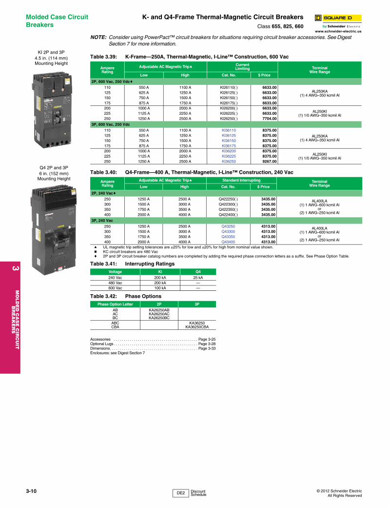
3M
OLD
ED
CA
SE
CIR
CU
IT
BR
EA
KE
RS
Molded Case Circuit Breakers
K- and Q4-Frame Thermal-Magnetic Circuit BreakersClass 655, 825, 660
NOTE: Consider using PowerPact™ circuit breakers for situations requiring circuit breaker acces
www.schneider-electric.ussories. See Digest Section 7 for more information.
a UL magnetic trip setting tolerances are ±25% for low and ±20% for high from nominal value shown.b KC circuit breakers are 480 Vacc 2P and 3P circuit breaker catalog numbers are completed by adding the required phase connection letters as a suffix. See Phase Option Table.
Accessories . . . . . . . . . . . . . . . . . . . . . . . . . . . . . . . . . . . . . . . . . . Page 3-25Optional Lugs . . . . . . . . . . . . . . . . . . . . . . . . . . . . . . . . . . . . . . . . . . Page 3-28Dimensions. . . . . . . . . . . . . . . . . . . . . . . . . . . . . . . . . . . . . . . . . . . . Page 3-33Enclosures: see Digest Section 7
Table 3.39: K-Frame—250A, Thermal-Magnetic, I-Line™ Construction, 600 Vac
AmpereRating
Adjustable AC Magnetic Tripa Current Limiting Terminal
Wire RangeLow High Cat. No. $ Price
2P, 600 Vac, 250 Vdcc
110 550 A 1100 A KI26110( ) 6633.00AL250KA
(1) 4 AWG–350 kcmil Al125 625 A 1250 A KI26125( ) 6633.00150 750 A 1500 A KI26150( ) 6633.00175 875 A 1750 A KI26175( ) 6633.00200 1000 A 2000 A KI26200( ) 6633.00
AL250KI(1) 1/0 AWG–350 kcmil Al225 1125 A 2250 A KI26225( ) 6633.00
250 1250 A 2500 A KI26250( ) 7704.00
3P, 600 Vac, 250 Vdc
110 550 A 1100 A KI36110 8375.00
AL250KA(1) 4 AWG–350 kcmil Al
125 625 A 1250 A KI36125 8375.00150 750 A 1500 A KI36150 8375.00175 875 A 1750 A KI36175 8375.00200 1000 A 2000 A KI36200 8375.00
AL250KI(1) 1/0 AWG–350 kcmil Al225 1125 A 2250 A KI36225 8375.00
250 1250 A 2500 A KI36250 9267.00
Table 3.40: Q4-Frame—400 A, Thermal-Magnetic, I-Line™ Construction, 240 Vac
AmpereRating
Adjustable AC Magnetic Tripa Standard Interrupting TerminalWire RangeLow High Cat. No. $ Price
2P, 240 Vacc
250 1250 A 2500 A Q422250( ) 3435.00 AL400LA(1) 1 AWG–600 kcmil Al
or(2) 1 AWG–250 kcmil Al
300 1500 A 3000 A Q422300( ) 3435.00350 1750 A 3500 A Q422350( ) 3435.00400 2000 A 4000 A Q422400( ) 3435.00
3P, 240 Vac
250 1250 A 2500 A Q43250 4313.00 AL400LA(1) 1 AWG–600 kcmil Al
or(2) 1 AWG–250 kcmil Al
300 1500 A 3000 A Q43300 4313.00350 1750 A 3500 A Q43350 4313.00400 2000 A 4000 A Q43400 4313.00
Table 3.41: Interrupting RatingsVoltage KI Q4
240 Vac 200 kA 25 kA480 Vac 200 kA —600 Vac 100 kA —
Table 3.42: Phase OptionsPhase Option Letter 2P 3P
ABACBC
KA26250ABKA26250ACKA26250BC
ABCCBA
KA36250KA36250CBA
Q4 2P and 3P6 in. (152 mm)
Mounting Height
KI 2P and 3P4.5 in. (114 mm) Mounting Height
3-10 © 2012 Schneider ElectricAll Rights Reserved
DE2 Discount Schedule

© 2012 Schneider ElectricAll Rights Reserved
Molded Case Circuit Breakers
L-Frame Thermal-Magnetic Circuit BreakersClass 600, 665, 736, 830
NOTE: Consider using PowerPact™ circuit breakers for situations requiring circuit breaker accessories. See Digest
3M
OL
DE
D C
AS
E C
IRC
UIT
B
RE
AK
ER
S
www.schneider-electric.us
Section 7 for more information.
a AC magnetic setting tolerances are +0–25% from max. value shown.
Accessories . . . . . . . . . . . . . . . . . . . . . . . . . . . . . . . . . . . . . Page 3-24—3-27Optional Lugs . . . . . . . . . . . . . . . . . . . . . . . . . . . . . . . . . . . . Page 3-28—3-29Dimensions . . . . . . . . . . . . . . . . . . . . . . . . . . . . . . . . . . . . . . . . . . . Page 3-33Enclosures: see Digest Section 7
Table 3.43: L-Frame—400 A, Thermal-Magnetic, Individually-Mounted, High Magnetic Withstand Circuit Breakers For Mission Critical Loads
AmpereRating
AC Magnetic Level Factory Seta
Standard Interrupting High Interrupting TerminalWire RangeCat. No. $ Price Cat. No. $ Price
LA/LH MC Circuit Breaker, 3P, 480 Vac
200 A 4000 A LAL34200MC 4962.00 LHL34200MC 7941.00AL250LA
(1) 4 AWG–350 kcmil Al225 A 4500 A LAL34225MC 4962.00 LHL34225MC 7941.00250 A 5000 A LAL34250MC 5355.00 LHL34250MC 8336.00
400 A 8000 A LAL34400MC 6615.00 LHL34400MC 9596.00 AL400LA
(1) 1 AWG–600 kcmil Al or(2) 1 AWG–250 kcmil Al
Table 3.44: L-Frame—600 A, Thermal-Magnetic, Individually-Mounted Circuit Breakers, 600 Vac
AmpereRating
Adjustable AC Magnetic Trip Standard Interrupting High Interrupting Terminal
Wire RangeLow High Cat. No. $ Price Cat. No. $ Price
2P, 600 Vac, 250 Vdc
125 A150 A175 A200 A225 A250 A
625 A750 A875 A
1000 A1125 A1250 A
1250 A1500 A1750 A2000 A2250 A2500 A
LAL26125LAL26150LAL26175LAL26200LAL26225LAL26250
3807.003807.003807.003807.003807.003807.00
LHL26125LHL26150LHL26175LHL26200LHL26225LHL26250
6362.006362.006362.006362.006362.006362.00
AL400LA(1) 1 AWG–600 kcmil Al
or(2) 1 AWG–250 kcmil Al
300 A350 A400 A
1500 A1750 A2000 A
3000 A3500 A4000 A
LAL26300LAL26350LAL26400
3807.003807.003807.00
LHL26300LHL26350LHL26400
6362.006362.006362.00
3P, 600 Vac, 250 Vdc
125 A150 A175 A200 A225 A250 A
625 A750 A875 A
1000 A1125 A1250 A
1250 A1500 A1750 A2000 A2250 A2500 A
LAL36125LAL36150LAL36175LAL36200LAL36225LAL36250
4619.004619.004619.004619.004619.004619.00
LHL36125LHL36150LHL36175LHL36200LHL36225LHL36250
7598.007598.007598.007598.007598.007598.00
AL400LA(1) 1 AWG–600 kcmil Al
or(2) 1 AWG–250 kcmil Al
300 A350 A400 A
1500 A1750 A2000 A
3000 A3500 A4000 A
LAL36300LAL36350LAL36400
4619.004619.004619.00
LHL36300LHL36350LHL36400
7598.007598.007598.00
Table 3.45: L-Frame—600 A, Current-Limiting, Individually-Mounted Circuit Breakers, 600 Vac
AmpereRating
Adjustable AC Magnetic Trip Extra-High Interrupting Current Limiting Terminal
Wire RangeLow High Cat. No. $ Price Cat. No. $ Price
2P, 600 Vac
300 A350 A400 A
1500 A1750 A2000 A
3200 A3200 A3200 A
LCL26300LCL26350LCL26400
7479.007479.007479.00
LIL26300LIL26350LIL26400
8604.008604.008604.00 AL600LI5
(2) 4/0 AWG–500 kcmil Al450 A500 A600 A
2250 A2500 A3000 A
4200 A4200 A4200 A
LCL26450LCL26500LCL26600
7823.007823.007823.00
LIL26450LIL26500LIL26600
12551.0012551.0012551.00
3P, 600 Vac
300 A350 A400 A
1500 A1750 A2000 A
3200 A3200 A3200 A
LCL36300LCL36350LCL36400
8312.008312.008312.00
LIL36300LIL36350LIL36400
9563.009563.009563.00 AL600LI5
(2) 4/0 AWG–500 kcmil Al450 A500 A600 A
2250 A2500 A3000 A
4200 A4200 A4200 A
LCL36450LCL36500LCL36600
8691.008691.008691.00
LIL36450LIL36500LIL36600
13949.0013949.0013949.00
Table 3.46: Interrupting RatingsVoltage LAL LHL LCL LIL
240 Vac 42 kA 65 kA 100 kA 200 kA480 Vac 30 kA 35 kA 65 kA 200 kA600 Vac 22 kA 25 kA 35 kA 100 kA
LAL/LHL MCFor Mission Critical
Power Loads available in 200, 225, 250,
and 400 A @ 480 Vac
LIL366002P and 3P 300–600 A
LAL/LHL2P and 3P125–400 A
3-11
DE2 Discount Schedule
3M
OLD
ED
CA
SE
CIR
CU
IT
BR
EA
KE
RS
Molded Case Circuit Breakers
L-Frame Thermal-Magnetic Circuit BreakersClass 600, 665, 736, 830
NOTE: Consider using PowerPact™ circuit breakers for situations requiring circuit breaker acces
www.schneider-electric.ussories. See Digest Section 7 for more information.
a Factory set AC magnetic setting tolerances are +0–25% from max. value shown.
a 2P and 3P circuit breaker catalog numbers are completed by adding the required phase connection letters as a suffix. See Phase Option Table.b UL magnetic trip setting tolerances are ±25% for low and ±20% for high from nominal value.
ccessories . . . . . . . . . . . . . . . . . . . . . . . . . . . . . . . . . . . . . . Page 3-24—3-27Optional Lugs . . . . . . . . . . . . . . . . . . . . . . . . . . . . . . . . . . . . Page 3-28—3-29Dimensions. . . . . . . . . . . . . . . . . . . . . . . . . . . . . . . . . . . . . . . . . . . . Page 3-33Enclosures: see Digest Section 7
Table 3.47: L-Frame—400 A, Thermal-Magnetic, I-Line™ Construction, High Magnetic Withstand Circuit Breakers For Mission Critical Loads
AmpereRating
AC Magnetic Level Factory Seta
Standard Interrupting High Interrupting TerminalWire RangeCat. No. $ Price Cat. No. $ Price
LA/LH MC Circuit Breaker, 3P, 480 Vac
200 A 4000 A LA34200MC 5571.00 LH34200MC 8771.00AL250LA
(1) 4 AWG–350 kcmil Al225 A 4500 A LA34225MC 5571.00 LH34225MC 8771.00250 A 5000 A LA34250MC 5681.00 LH34250MC 8882.00
400 A 8000 A LA34400MC 7241.00 LH34400MC 10142.00 AL400LA
(1) 1 AWG–600 kcmil Al or(2) 1 AWG–250 kcmil Al
Table 3.48: L-Frame—600 A, Thermal-Magnetic I-Line™ Construction Circuit Breakers, 600 Vac
AmpereRating
Adjustable AC Magnetic Tripb Standard Interrupting High Interrupting Terminal
Wire RangeLow High Cat. No. $ Price Cat. No. $ Price
2P, 600 Vac, 250 Vdca
125 A150 A175 A200 A225 A250 A
625 A750 A875 A
1000 A1125 A1250 A
1250 A1500 A1750 A2000 A2250 A2500 A
LA26125( )LA26150( )LA26175( )LA26200( )LA26225( )LA26250( )
4053.004053.004053.004053.004053.004053.00
LH26125( )LH26150( )LH26175( )LH26200( )LH26225( )LH26250( )
6762.006762.006762.006762.006762.006762.00
AL400LA(1) 1 AWG–600 kcmil Al
or(2) 1 AWG–250 kcmil Al
300 A350 A400 A
1500 A1750 A2000 A
3000 A3500 A4000 A
LA26300( )LA26350( )LA26400( )
4053.004053.004053.00
LH26300( )LH26350( )LH26400( )
6762.006762.006762.00
3P, 600 Vac, 250 Vdc
125 A150 A175 A200 A225 A250 A
625 A750 A875 A
1000 A1125 A1250 A
1250 A1500 A1750 A2000 A2250 A2500 A
LA36125LA36150LA36175LA36200LA36225LA36250
4944.004944.004944.004944.004944.004944.00
LH36125LH36150LH36175LH36200LH26225LH36250
8145.008145.008145.008145.008145.008145.00
AL400LA(1) 1 AWG–600 kcmil Al
or(2) 1 AWG–250 kcmil Al
300 A350 A400 A
1500 A1750 A2000 A
3000 A3500 A4000 A
LA36300LA36350LA36400
4944.004944.004944.00
LH36300LH36350LH36400
8145.008145.008145.00
Table 3.49: L-Frame—600 A, Current-Limiting, I-Line™ Construction, Circuit Breakers, 600 Vac
AmpereRating
Adjustable AC Magnetic Tripb Extra-High Interrupting Current Limiting Terminal
Wire RangeLow High Cat. No. $ Price Cat. No. $ Price
2P, 600 Vaca
300 A350 A400 A
1500 A1750 A2000 A
3200 A3200 A3200 A
LC26300( )LC26350( )LC26400( )
8312.008312.008312.00
LI26300( )LI26350( )LI26400( )
9563.009563.009563.00 AL600LI5
(2) 4/0 AWG–500 kcmil Al450 A500 A600 A
2250 A2500 A3000 A
4200 A4200 A4200 A
LC26450( )LC26500( )LC26600( )
8691.008691.008691.00
LI26450( )LI26500( )LI26600( )
13949.0013949.0013949.00
3P, 600 Vac
300 A350 A400 A
1500 A1750 A2000 A
3200 A3200 A3200 A
LC36300LC36350LC36400
9234.009234.009234.00
LI36300LI36350LI36400
10673.0010673.0010673.00 AL600LI5
(2) 4/0 AWG–500 kcmil Al450 A500 A600 A
2250 A2500 A3000 A
4200 A4200 A4200 A
LC36450LC36500LC36600
9657.009657.009657.00
LI36450LI36500LI36600
15498.0015498.0015498.00
Table 3.50: Interrupting RatingsVoltage LA LH LC LI
240 Vac 42 kA 65 kA 100 kA 200 kA480 Vac 30 kA 35 kA 65 kA 200 kA600 Vac 22 kA 25 kA 35 kA 100 kA
Table 3.51: Phase OptionsPhase Option Letter 2P 3P
ABACBC
LA26400ABLA26400ACLA26400BC
ABCCBA
LA36400LA36400CBA
LA / LH 2P and 3P6 in. (152 mm)
Mounting Height
LC 2P and 3P7.5 in. (190 mm)Mounting Height
LI 2P and 3P7.5 in. (190 mm)Mounting Height
3-12 © 2012 Schneider ElectricAll Rights Reserved
DE2 Discount Schedule
© 2012 Schneider ElectricAll Rights Reserved
Molded Case Circuit Breakers
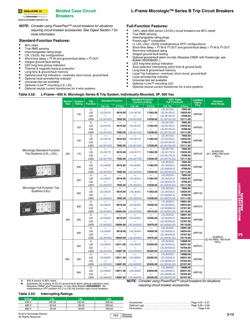
L-Frame Micrologic™ Series B Trip Circuit Breakers
3M
OL
DE
D C
AS
E C
IRC
UIT
B
RE
AK
ER
S
www.schneider-electric.us
NOTE: Consider using PowerPact™ circuit breakers for situations requiring circuit breaker accessories. See Digest Section 7 for more information.
Standard-Function Features:• 80% rated• True RMS sensing• Interchangeable rating plugs• LSI, LS(I)G, trip configurations• Short-time delay = I2t IN and ground-fault delay = I2t OUT• Integral ground-fault testing• LED long-time pickup indication• Thermal & magnetic backup protection• Long-time & ground-fault memory• Optional local trip indicators—overload, short circuit, ground-fault• Optional local ammeter/trip indicator• Universal test set available• Optional I-Line™ mounting (LX, LXI)• Optional neutral current transformer for 4-wire systems
Full-Function Features:• 100% rated (600 sensor LE/LEL) circuit breakers are 80% rated)• True RMS sensing• Interchangeable rating plugs• PowerLogic™ compatible• LI, LIG, LS(I), LS(I)G (instantaneous OFF) configurations• Short-time delay = I2t IN & I2t OUT and ground-fault delay = I2t IN & I2t OUT• Short-time withstand rating• Integral ground-fault testing• Optional ground-fault alarm (no trip) (Requires CIM3F with PowerLogic, see
Bulletin 0502DB0001.)• LED long-time pickup indication• Zone-selective interlocking (short-time & ground-fault)• Long-time & ground-fault memory• Local Trip Indicators—overload, short circuit, ground-fault• Local ammeter/trip indicator• Universal test set available• Optional I-Line™ mounting (LE)• Optional neutral current transformer for 4-wire systems
Table 3.52: L-Frame—600 A, Micrologic Series B Trip System, Individually-Mounted, 3P, 600 Vac
SensorSize
AmpereRating
TripFunction
Standard Function Standard FunctionCurrent Limiting
100% Rated Full Functionb
Installed Rating Plug
Terminal Wire Range
Cat. No. $ Price Cat. No. $ Price Cat. No. $ Price
250
100
LI — — — — LEL36100LI 7692.00
ARP040
AL600LI35(2) 1 AWG–350 kcmil
Al/Cu
LSI LXL36100 5616.00 LXIL36100 11262.00 LEL36100LS 13035.00LIG — — — — LEL36100LIG 9768.00
LSIG LXL36100G 7692.00 LXIL36100G 13338.00 LEL36100LSG 15111.00
125
LI — — — — LEL36125LI 7692.00
ARP050LSI LXL36125 5616.00 LXIL36125 11262.00 LEL36125LS 13035.00LIG — — — — LEL36125LIG 9768.00
LSIG LXL36125G 7692.00 LXIL36125G 13338.00 LEL36125LSG 15111.00
150
LI — — — — LEL36150LI 7692.00
ARP060LSI LXL36150 5616.00 LXIL36150 11262.00 LEL36150LS 13035.00LIG — — — — LEL36150LIG 9768.00
LSIG LXL36150G 7692.00 LXIL36150G 13338.00 LEL36150LSG 15111.00
175
LI — — — — LEL36175LI 7692.00
ARP070LSI LXL36175 5616.00 LXIL36175 11262.00 LEL36175LS 13035.00LIG — — — — LEL36175LIG 9768.00
LSIG LXL36175G 7692.00 LXIL36175G 13338.00 LEL36175LSG 15111.00
200
LI — — — — LEL36200LI 7692.00
ARP080LSI LXL36200 5616.00 LXIL36200 11262.00 LEL36200LS 13035.00LIG — — — — LEL36200LIG 9768.00
LSIG LXL36200G 7692.00 LXIL36200G 13338.00 LEL36200LSG 15111.00
225
LI — — — — LEL36225LI 7692.00
ARP090LSI LXL36225 5616.00 LXIL36225 11262.00 LEL36225LS 13035.00LIG — — — — LEL36225LIG 9768.00
LSIG LXL36225G 7692.00 LXIL36225G 13338.00 LEL36225LSG 15111.00
250
LI — — — — LEL36250LI 7692.00
ARP100LSI LXL36250 5616.00 LXIL36250 11262.00 LEL36250LS 13035.00LIG — — — — LEL36250LIG 9768.00
LSIG LXL36250G 7692.00 LXIL36250G 13338.00 LEL36250LSG 15111.00
400
300
LI — — — — LEL36300LI 10691.00
ARP075
AL600LI5(2) 4/0 AWG– 500 kcmil
Al/Cu
LSI LXL36300 8618.00 LXIL36300 16400.00 LEL36300LS 16034.00LIG — — — — LEL36300LIG 12767.00
LSIG LXL36300G 10694.00 LXIL36300G 18476.00 LEL36300LSG 18110.00
350
LI — — — — LEL36350LI 10691.00
ARP088LSI LXL36350 8618.00 LXIL36350 16400.00 LEL36350LS 16034.00LIG — — — — LEL36350LIG 12767.00
LSIG LXL36350G 10694.00 LXIL36350G 18476.00 LEL36350LSG 18110.00
400
LI — — — — LEL36400LI 10691.00
ARP100LSI LXL36400 8618.00 LXIL36400 16400.00 LEL36400LS 16034.00LIG — — — — LEL36400LIG 12767.00
LSIG LXL36400G 10694.00 LXIL36400G 18476.00 LEL36400LSG 18110.00
600
450
LI — — — — LEL36450LI 14688.00
ARP075LSI LXL36450 12611.00 LXIL36450 23250.00 LEL36450LS 20031.00LIG — — — — LEL36450LIG 16764.00
LSIG LXL36450G 14687.00 LXIL36450G 25326.00 LEL36450LSG 22107.00
500
LI — — — — LEL36500LI 14688.00
ARP083LSI LXL36500 12611.00 LXIL36500 23250.00 LEL36500LS 20031.00LIG — — — — LEL36500LIG 16764.00
LSIG LXL36500G 14687.00 LXIL36500G 25326.00 LEL36500LSG 22107.00
600
LI — — — — LEL36600LI 14688.00
ARP100LSI LXL36600 12611.00 LXIL36600 23250.00 LEL36600LS 20031.00LIG — — — — LEL36600LIG 16764.00
LSIG LXL36600G 14687.00 LXIL36600G 25326.00 LEL36600LSG 22107.00a 600 A sensor is 80% ratedb Substitute (A) in place of (G) for ground-fault alarm (pickup indication only).
Requires CIM3F and Powerlogic, or see Data Bulletin 0502DB0001. No instantaneous OFF position for LI or LIG trip function type circuit breakers.
NOTE: Consider using PowerPact™ circuit breakers for situations requiring circuit breaker accessories.
Table 3.53: Interrupting RatingsVoltage LXL LEL LXIL240 V 100 kA 100 kA 200 kA Accessories . . . . . . . . . . . . . . . . . . . . . . . . . . . . . . . . . . . . . Page 3-24—3-27
Optional Lugs . . . . . . . . . . . . . . . . . . . . . . . . . . . . . . . . . . . . Page 3-28—3-29Dimensions . . . . . . . . . . . . . . . . . . . . . . . . . . . . . . . . . . . . . . . . . . . .Page 3-33
480 V 65 kA 65 kA 200 kA600 V 35 kA 35 kA 100 kA
Micrologic Standard-Function Trip Systems (LXL, LXIL)
Micrologic Full-Function Trip Systems (LEL)
3-13
DE2 Discount Schedule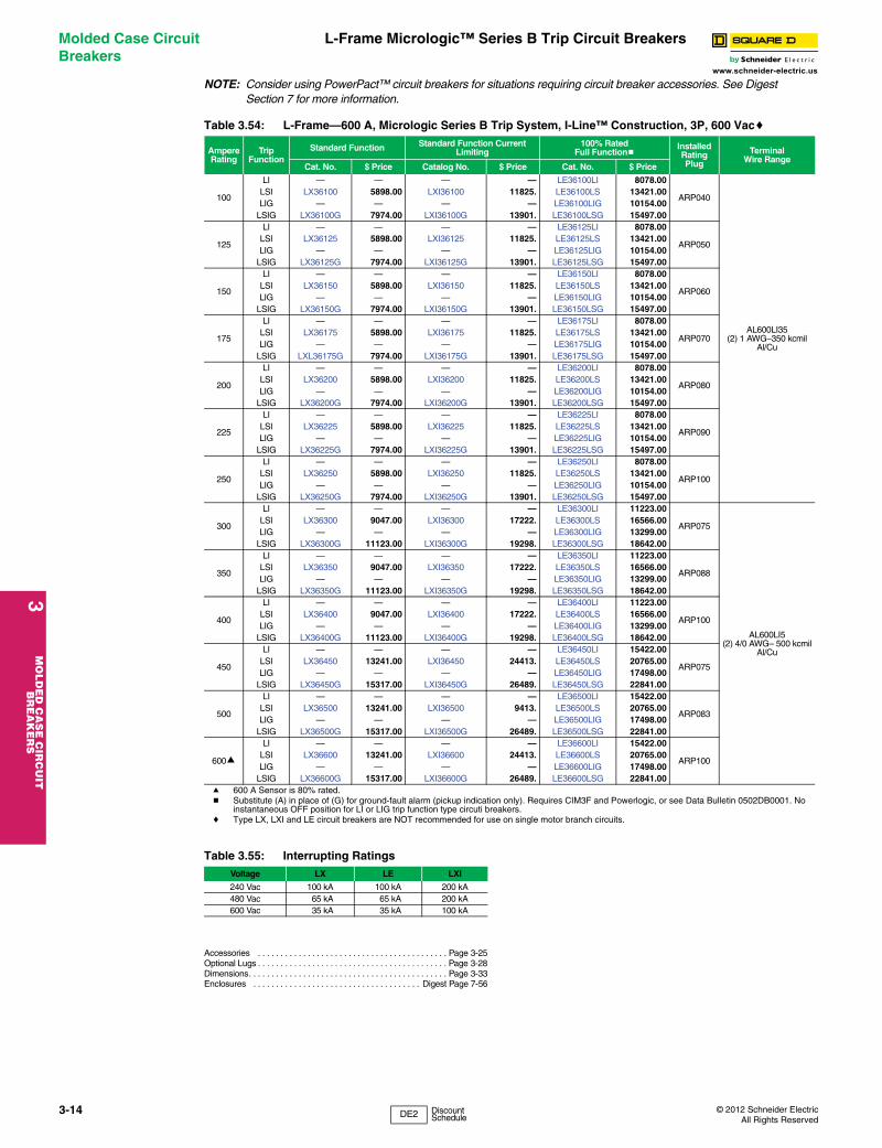
3M
OLD
ED
CA
SE
CIR
CU
IT
BR
EA
KE
RS
Molded Case Circuit Breakers
L-Frame Micrologic™ Series B Trip Circuit Breakers
NOTE: Consider using PowerPact™ circuit breakers for situations requiring circuit breaker accessor
www.schneider-electric.usies. See Digest Section 7 for more information.
Accessories . . . . . . . . . . . . . . . . . . . . . . . . . . . . . . . . . . . . . . . . . . Page 3-25Optional Lugs . . . . . . . . . . . . . . . . . . . . . . . . . . . . . . . . . . . . . . . . . . Page 3-28Dimensions. . . . . . . . . . . . . . . . . . . . . . . . . . . . . . . . . . . . . . . . . . . . Page 3-33Enclosures . . . . . . . . . . . . . . . . . . . . . . . . . . . . . . . . . . . . . Digest Page 7-56
Table 3.54: L-Frame—600 A, Micrologic Series B Trip System, I-Line™ Construction, 3P, 600 Vacc
AmpereRating
TripFunction
Standard Function Standard Function Current Limiting
100% Rated Full Functionb
Installed Rating Plug
Terminal Wire Range
Cat. No. $ Price Catalog No. $ Price Cat. No. $ Price
100
LI — — — — LE36100LI 8078.00
ARP040
AL600LI35(2) 1 AWG–350 kcmil
Al/Cu
LSI LX36100 5898.00 LXI36100 11825. LE36100LS 13421.00LIG — — — — LE36100LIG 10154.00
LSIG LX36100G 7974.00 LXI36100G 13901. LE36100LSG 15497.00
125
LI — — — — LE36125LI 8078.00
ARP050LSI LX36125 5898.00 LXI36125 11825. LE36125LS 13421.00LIG — — — — LE36125LIG 10154.00
LSIG LX36125G 7974.00 LXI36125G 13901. LE36125LSG 15497.00
150
LI — — — — LE36150LI 8078.00
ARP060LSI LX36150 5898.00 LXI36150 11825. LE36150LS 13421.00LIG — — — — LE36150LIG 10154.00
LSIG LX36150G 7974.00 LXI36150G 13901. LE36150LSG 15497.00
175
LI — — — — LE36175LI 8078.00
ARP070LSI LX36175 5898.00 LXI36175 11825. LE36175LS 13421.00LIG — — — — LE36175LIG 10154.00
LSIG LXL36175G 7974.00 LXI36175G 13901. LE36175LSG 15497.00
200
LI — — — — LE36200LI 8078.00
ARP080LSI LX36200 5898.00 LXI36200 11825. LE36200LS 13421.00LIG — — — — LE36200LIG 10154.00
LSIG LX36200G 7974.00 LXI36200G 13901. LE36200LSG 15497.00
225
LI — — — — LE36225LI 8078.00
ARP090LSI LX36225 5898.00 LXI36225 11825. LE36225LS 13421.00LIG — — — — LE36225LIG 10154.00
LSIG LX36225G 7974.00 LXI36225G 13901. LE36225LSG 15497.00
250
LI — — — — LE36250LI 8078.00
ARP100LSI LX36250 5898.00 LXI36250 11825. LE36250LS 13421.00LIG — — — — LE36250LIG 10154.00
LSIG LX36250G 7974.00 LXI36250G 13901. LE36250LSG 15497.00
300
LI — — — — LE36300LI 11223.00
ARP075
AL600LI5(2) 4/0 AWG– 500 kcmil
Al/Cu
LSI LX36300 9047.00 LXI36300 17222. LE36300LS 16566.00LIG — — — — LE36300LIG 13299.00
LSIG LX36300G 11123.00 LXI36300G 19298. LE36300LSG 18642.00
350
LI — — — — LE36350LI 11223.00
ARP088LSI LX36350 9047.00 LXI36350 17222. LE36350LS 16566.00LIG — — — — LE36350LIG 13299.00
LSIG LX36350G 11123.00 LXI36350G 19298. LE36350LSG 18642.00
400
LI — — — — LE36400LI 11223.00
ARP100LSI LX36400 9047.00 LXI36400 17222. LE36400LS 16566.00LIG — — — — LE36400LIG 13299.00
LSIG LX36400G 11123.00 LXI36400G 19298. LE36400LSG 18642.00
450
LI — — — — LE36450LI 15422.00
ARP075LSI LX36450 13241.00 LXI36450 24413. LE36450LS 20765.00LIG — — — — LE36450LIG 17498.00
LSIG LX36450G 15317.00 LXI36450G 26489. LE36450LSG 22841.00
500
LI — — — — LE36500LI 15422.00
ARP083LSI LX36500 13241.00 LXI36500 9413. LE36500LS 20765.00LIG — — — — LE36500LIG 17498.00
LSIG LX36500G 15317.00 LXI36500G 26489. LE36500LSG 22841.00
600a
LI — — — — LE36600LI 15422.00
ARP100LSI LX36600 13241.00 LXI36600 24413. LE36600LS 20765.00LIG — — — — LE36600LIG 17498.00
LSIG LX36600G 15317.00 LXI36600G 26489. LE36600LSG 22841.00a 600 A Sensor is 80% rated.b Substitute (A) in place of (G) for ground-fault alarm (pickup indication only). Requires CIM3F and Powerlogic, or see Data Bulletin 0502DB0001. No
instantaneous OFF position for LI or LIG trip function type circuti breakers.c Type LX, LXI and LE circuit breakers are NOT recommended for use on single motor branch circuits.
Table 3.55: Interrupting RatingsVoltage LX LE LXI
240 Vac 100 kA 100 kA 200 kA480 Vac 65 kA 65 kA 200 kA600 Vac 35 kA 35 kA 100 kA
3-14 © 2012 Schneider ElectricAll Rights Reserved
DE2 Discount Schedule
© 2012 Schneider ElectricAll Rights Reserved
Molded Case Circuit Breakers
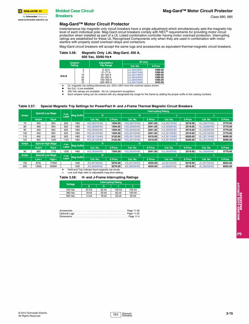
Mag-Gard™ Motor Circuit ProtectorClass 680, 685
3M
OL
DE
D C
AS
E C
IRC
UIT
B
RE
AK
ER
S
www.schneider-electric.us
Mag-Gard™ Motor Circuit ProtectorInstantaneous trip magnetic only circuit breakers have a single adjustment which simultaneously sets the magnetic trip level of each individual pole. Mag-Gard circuit breakers comply with NEC® requirements for providing motor circuit protection when installed as part of a UL Listed combination controller having motor overload protection. Interrupting ratings are established for these UL Recognized Components only when they are used in combination with motor starters with properly sized overload relays and contactors.Mag-Gard circuit breakers will accept the same lugs and accessories as equivalent thermal-magnetic circuit breakers.
a UL magnetic trip setting tolerances are -20%/+30% from the nominal values shown.b No GJL I-Line available.c 250 Vdc ratings are available . No UL component recognition.d Each ampere rating can be ordered with any designated trip range for the frame by adding the proper suffix to the catalog numbers.
e Hold and Trip indicate fixed magnetic trip levelsf Low and High refer to adjustable mag level setting.
Accessories . . . . . . . . . . . . . . . . . . . . . . . . . . . . . . . . . . . . . . . . . Page 11-30Optional Lugs . . . . . . . . . . . . . . . . . . . . . . . . . . . . . . . . . . . . . . . . Page 11-25Dimensions . . . . . . . . . . . . . . . . . . . . . . . . . . . . . . . . . . . . . . . . . . . Page 11-4
Table 3.56: Magnetic Only LAL Mag-Gard, 400 A, 600 Vac, 50/60 Hzc
AmpereRating
AdjustableaTrip Range
3P only
Cat. No. $ Price
GJLb
37
15305075
9–33 A21–77 A45–165 A90–330 A150–550 A225–825 A
GJL36003M01GJL36007M02GJL36015M03GJL36030M04GJL36050M05GJL36075M06
1089.001089.001089.001089.001380.001643.00
Table 3.57: Special Magnetic Trip Settings for PowerPact H- and J-Frame Thermal Magnetic Circuit Breakers
AmpsSpecial Low Mags Ii on
Label Mag Suffix
Interrupting Rating
D G J L
Holde Tripe Cat. No. $ Price Cat. No. $ Price Cat. No. $ Price Cat. No. $ Price
70 400 850 625 H83 HDL36070H83 1594.00 HGL36070H83 2041.00 HJL36070H83 2519.00 HLL36070H83 3779.0080 400 850 625 H83 HDL36080H83 1594.00 HGL36080H83 2041.00 HJL36080H83 2519.00 HLL36080H83 3779.0090 400 850 625 H83 HDL36090H83 1594.00 HGL36090H83 2041.00 HJL36090H83 2519.00 HLL36090H83 3779.00100 400 850 625 H83 HDL36100H83 1594.00 HGL36100H83 2041.00 HJL36100H83 2519.00 HLL36100H83 3779.00110 400 850 625 H83 HDL36110H83 3120.00 HGL36110H83 4319.00 HJL36110H83 6209.00 HLL36110H83 8099.00125 800 1450 1125 H84 HDL36125H84 3120.00 HGL36125H84 4319.00 HJL36125H84 6209.00 HLL36125H84 8099.00
Amps Special High Mags Ii on Label Mag Suffix
D G J L
Holde Tripe Cat. No. $ Price Cat. No. $ Price Cat. No. $ Price Cat. No. $ Price
90 900 1700 1300 H85 HDL36090H85 1594.00 HGL36090H85 2041.00 HJL36090H85 2519.00 HLL36090H85 3779.00
Amps Special Low Mags Ii on Label Mag Suffix
D G J L
Lowf Highf Cat. No. $ Price Cat. No. $ Price Cat. No. $ Price Cat. No. $ Price
150 875L 1750H H29 JDL36150H29 3276.00 JGL36150H29 4535.00 JJL36150H29 6518.00 JLL36150H29 8503.00200 1250L 2500H H32 JDL36200H32 3276.00 JGL36200H32 4535.00 JJL36200H32 6518.00 JLL36200H32 8503.00
Table 3.58: H- and J-Frame Interrupting Ratings
VoltageInterrupting Rating
D G J L240 Vac 25 KA 65 kA 100 kA 125 kA480 Vac 18 kA 35 kA 65 kA 100 kA600 Vac 14 kA 18 kA 25 kA 50 kA
3-15
DE2 Discount Schedule
3M
OLD
ED
CA
SE
CIR
CU
IT
BR
EA
KE
RS
Molded Case Circuit Breakers
GJ-Frame MCP SelectionClass 680
Adjustable instantaneous-trip circuit breakers are intended 2. Determine motor hp rating from the
www.schneider-electric.usfor use in combination with motor starters with overload relays for the protection of motor circuits from short circuits. Other specific applications include rectifiers and resistance welders. These circuit breakers contain a magnetic trip element in each pole with the trip point adjustable from the front. Interrupting ratings are determined by testing the instantaneous-trip circuit breakers in combination with a contactor and overload relay.
Select instantaneous-trip circuit breakers as follows:This selection table is suitable for motors, other than NEMA Design E, with locked-rotor indicating code letters per NEC® Table 430.7 (b) as follows:
1. For other motors order a special thermal-magnetic circuit breaker with magnetic trip settings for the specific motor— specify motor horsepower, voltage, frequency, full-load current and code letter or locked rotor current.
motor nameplate.3. Refer to the tables and select an instantaneous-trip circuit
breaker with an ampere rating recommended for the hp and voltage involved.
4. Select an adjustable trip setting of at least 800%, not to exceed 1300%, of the motor full-load amperes (FLA) for other than Design E motors. For Design E motors, select an adjustable trip setting of at least 1100% not to exceed 1700% of FLA.
5. The NEC 1300% maximum setting may be inadequate for instantaneous-trip circuit breakers to withstand current surges typical of the magnetization current of autotransformer type reduced voltage starters, or open transition wye-delta starters during transfer from “start” to “run,” constant hp multi-speed motors, and motors labeled “high efficiency.” Select thermal-magnetic circuit breakers from Digest page 7-32 for those applications.
6. Part-winding motors, per NEC 430.3, should have two circuit breakers selected from the above at not more than one half the allowable trip setting for the horsepower rating. The two circuit breakers should operate simultaneously as a disconnecting means per NEC 430.103.
7. Based on NEC 430.52 and NEC Table 430.150. See Digest page 7-30 for a available Adjustable Instantaneous-Trip Circuit Breakers.
Table 3.59: Locked-Rotor Indicating Codes
Horsepower Motor Code letter
1/2 or less3/4 to 1-1/2
2 to 35 to 25
30 to 125150 or more
A–LA–KA–JA–HA–GA–F
Table 3.60: GJL Adjustable Instantaneous-Trip Circuit Breakers for Single Motor Circuit ProtectionHp Ratings of Induction Type
Squirrel-Cage andWound Rotor Motors Full
LoadAmperesa
GJL FamilyMag-Gard
Circuit BreakerCat. No.
Magnetic TripSettingsb
Hp Ratings of Induction Type Squirrel-Cage and
Wound Rotor Motors FullLoad
Amperesa
GJL FamilyMag-Gard
Circuit BreakerCat. No.
Magnetic TripSettingsb
3Ø 60 Hz 3Ø 60 Hz
200 Vac
230 Vac
460 Vac
575 Vac MIN MAX 200
Vac230 Vac
460 Vac
575 Vac MIN MAX
1/2 0.8 GJL36003M01c 1100% 4100% 7-1/2 9 GJL36015M03 500% 1800%1/2 1 GJL36003M01c 900% 3300% 3 9.6 GJL36015M03 500% 1700%
3/4 1.1 GJL36003M01c 800% 3000% 3 7-1/2 10 11 GJL36015M03 400% 1500%3/4 1.4 GJL36003M01 600% 2400% 10 14 GJL36030M04 600% 2400%
1 1.8 GJL36003M01 500% 1800% 5 15.2 GJL36030M04 600% 2200%1/2 2 GJL36003M01 500% 1700% 15 17 GJL36030M04 500% 1900%
1-1/2 2.1 GJL36003M01 400% 1600% 5 17.5 GJL36030M04 500% 1900%1/2 2.3 GJL36003M01 400% 1400% 15 21 GJL36030M04 400% 1600%
1-1/2 2.6 GJL36003M01 300% 1300% 7-1/2 20 22 GJL36030M04 400% 1500%2 2.7 GJL36003M01d 300% 1200% 7-1/2 25.3 GJL36030M04 400% 1300%
3/4 2.8 GJL36003M01d 300% 1200% 20 25 27 GJL36050M05 600% 2000%3/4 3.2 GJL36007M02 700% 2400% 10 28 GJL36050M05 500% 2000%
2 3.4 GJL36007M02 600% 2300% 30 32 GJL36050M05 500% 1700%1 3.6 GJL36007M02 600% 2100% 10 32.2 GJL36050M05 500% 1700%
3 3.9 GJL36007M02 500% 2000% 25 34 GJL36050M05 400% 1600%1 4.1 GJL36007M02 500% 1900% 30 40 GJL36050M05 400% 1400%
3 4.8 GJL36007M02 400% 1600% 40 41 GJL36050M05 400% 1300%1-1/2 5.2 GJL36007M02 400% 1500% 15 42 GJL36075M06 400% 1300%
1-1/2 6 GJL36007M02 400% 1300% 15 48.3 GJL36075M06 500% 1700%5 6.1 GJL36015M03 700% 2700% 40 50 52 GJL36075M06 400% 1600%
2 6.8 GJL36015M03 700% 2400% 20 54 GJL36075M06 400% 1500%5 7.6 GJL36015M03 600% 2200% 20 60 62 GJL36075M06 400% 1300%
2 7.8 GJL36015M03 600% 2100% 50 65 GJL36075M06 300% 1300%a Motor full-load currents are taken from NEC Table 430.150. Select wire and circuit breakers on basis of horsepower rather than nameplate full-load current
per NEC 430.6 (A) for general motor applications. Do not use these values to select overload relay thermal units. See Digest pages 14-129–14-152 for selection of thermal units when actual full load current is not known. The voltages listed are rated motor voltages. Corresponding nominal system voltages are 200–208, 220–240, 440–480 and 550–600 V.
b Only MIN and MAX settings are shown, intermediate settings are available on all circuit breakers.c See NEC 430.52(A) for circuit breaker settings above 800%.d If due to motor starting characteristics, trip settings at the 1300% maximum permitted level are needed, the next size Mag-Gard circuit breaker should be
chosen.
3-16 © 2012 Schneider ElectricAll Rights Reserved

© 2012 Schneider ElectricAll Rights Reserved
Special Construction Circuit Breakers
Special Terminal Connectors and LugsClass 600
ctor
3M
OL
DE
D C
AS
E C
IRC
UIT
B
RE
AK
ER
S
www.schneider-electric.us
Bolt-On I-Line™ (20% Price Adder)The standard I-Line circuit breaker is designed to provide a high quality, secure connection between the distribution bus and circuit breaker. I-Line circuit breakers use plug-on type line-side connectors. The parallel line-side connectors “clamp’’ around the bus bars. In case of a short circuit, the increased magnetic flux causes the connectors to grasp the bus bars even tighter. I-Line circuit breakers with bolted connections have clamp-on jaws that are bolted around the main bus, as shown. The bolt-on I-Line design is offered as an alternative in order to meet specifications requiring a bolted connection. Bolt-on I-Line construction is available on FY, QB, QD, QG, QJ, Q4, FA, FH, FI, KI, LA, and LH frame circuit breakers and molded case switches, and SL100, SL225 and SL400 sub-feed lugs.
To order on all products except QB, QD, QG and QJ, simply add the letter “B’’ in the catalog number prefix of the circuit breaker, e.g., FA36100 becomes FAB36100. For QB, QD, QG and QJ, insert the letter “E” in the third position, e.g., QBE, QDE, etc.NOTE: Not available on Powerpact™ circuit breakers.
Top-Feed I-Line (No Additional Charge)I-Line panelboards may require the use of a top-feed I-Line circuit breaker in applications where a top-feed main circuit breaker is required. This involves having the I-Line jaw connectors on the OFF end of the circuit breaker, as opposed to the standard location on the ON end of the circuit breaker. To designate this construction, simply place the suffix “MT” at the end of the circuit breaker catalog number, e.g., FA36100 becomes FA36100MT. On LA or LH top-feed I-Line circuit breakers, accessories must be factory installed. This option is available in PowerPact™ H and J-frame by placing a “K” in the 4th position (termination indicator) of the circuit breaker catalog number, e.g., HGA36125 becomes HGK36125. This option is not available on L-frame (600 A only), M-frame, N-Frame or Powerpact M-, P- and R-frame.
“CBA” I-Line Jaw Configuration (Non-PowerPact Circuit Breaker) (No Additional Charge)Standard 1-pole and 2-pole I-Line circuit breakers are ordered by designating the required phase connection letters as a suffix to the circuit breaker catalog number. 3-pole circuit breakers do not require this phase designation and are supplied with an “ABC” phase jaw configuration as standard. In most applications this is acceptable since the phase loading is evenly distributed. In applications where the phases must be reversed it is possible to order a “CBA” jaw configuration by simply placing the letters “CBA” at the end of the standard catalog number, e.g., FA36100 becomes FA36100CBA.
Control Wire Tap Lugs (No Additional Charge if Field Installed; 20% Price Adder if Factory Installed) Control wire tap lugs are used in applications requiring connection to a small wire (22-14 AWG) for control circuits. This is accomplished by crimping the wire to a standard wire crimp terminal (not included) and fastening the terminal to the circuit breaker lug. On LA lugs, the lug is drilled to accept a 6-32 screw (included) to secure the crimp connector. On FA lugs, a flat slip-on crimp connector is used to attach to a shim-like connector placed under the circuit breaker lug.
Note: To order as a factory-installed device on FA, FH, FI, KI, Q4, LA, LH, LC, LI, LXI, LX or LC circuit breakers, add suffix number 8041 to circuit breaker catalog number, e.g., KIL362258041. To order as a factory-installed device on MG, MJ, PG, PJ, PL RG, RJ and RL use the product selector or the respective PowerPact catalog. Tapped lugs will be installed on the “ON” and “OFF” ends of the circuit breaker.
a Use fully-insulated 0.250 in slip-on connectors.
b I-Line Only.
Table 3.61: Control Wire Terminations for Circuit Breakers
Circuit Breaker
Control Wire Termination Kits
Cat. No.StandardPackageQuantity
$ PricePer Lug
FactoryInstalled $ Price
(Suffix 8041)
FA, FH, FI FATa 1 8.40
Add 20%to price of
circuit breaker
KI AL250KIT 1 113.00Q4, LA, LH AL400LAT 1 40.80
LC, LI, LXI, LX, LE
AL600LI35T 1 53.00AL600LI5T 1 44.60
MA, MH, MX, ME AL900MAT 1 111.00AL1000MAT 1 111.00
NA, NC, NX, NE AL1200NE6T 1 228.00
Table 3.62: Tapped Lugs for PowerPact™ Circuit Breakers
Circuit Breaker AmperesMax. Kit Cat. No. Standard
Package Qty. $ Price Per Kit
MG, MJ,PG, PJ, PL 800 A
AL800M23TK 3 312.00AL800P6TK 3 458.00
PG, PJ, PL
800 AAL800M23TK4 4 414.00AL800P6TK4 4 608.00
1200 AAL1200P24TK 1 138.00AL1200P25TK 3 416.00AL1200P25TK4 4 555.00
RG, RJ, RL 1200 A AL1200R53TKb 1 237.00
Plug-on Conne
Bolted Connector
Control WireMounting Screw
Circuit BreakerTerminal
Control Wire
AL250KAT Lug
AS
KC
809
Lug
BSKC 394
Lug Mounting Screw
Circuit Breaker Lug
Circuit Breaker Terminal
Control Wire Terminal(Catalog Number FAT)
3-17
DE2 Discount Schedule
3M
OLD
ED
CA
SE
CIR
CU
IT
BR
EA
KE
RS
Special Construction Circuit Breakers
Special Calibration, Rear-Connected Studs, Visi-Blade,Moisture/Fungus Treatment, and Short LA/LH Handle
www.schneider-electric.us
Special Magnetic or Thermal Calibration (20% Price Adder)
MagneticThe magnetic trip ranges for standard circuit breakers are listed in the Square D Digest. Requirements outside this range are best accommodated by selecting another standard circuit breaker. In some cases where this is not practical, a circuit breaker may be ordered with special magnetic calibration. Special magnetic calibration is not possible in all cases. Circuit breakers with special magnetic calibration and an adjustable magnetic trip range are not UL Listed; those with a fixed magnetic trip setting are UL Listed. Consult Schneider Electric local sales office for more information.
50 Degrees CUL 489 Listed molded case circuit breakers are calibrated for 40 degree C ambient temperature. To meet requirements of higher ambient conditions, circuit breakers can be factory calibrated for a 50 degree C ambient temperature. Circuit breakers with special thermal calibration are not UL Listed. To order 50° calibration, add “35” suffix to FA/FH/LA/LH or CA to H or J thermal magnetic breakers and add 20% to the List price of the breaker. Consult local sales office for more information.
Rear-Connected StudsRear-connected studs are designed to allow rear termination in applications such as control panels where wire gutter space may be limited. The studs may be bolted directly to the bus or lugs may be attached to the studs.NOTE: Long and short studs must be alternated on adjacent poles to assure proper electrical clearance
Note: Use alternate size studs on adjacent poles to obtain proper electrical clearance.
Visi-BladeTM Circuit Breakers (20% Price Adder)Visi-blade construction is a modification to the cover of a thermal-magnetic circuit breaker, a molded case switch, or a Mag-Gard™ circuit breaker which provides a “window” through which the position of the movable contacts can be verified. Luminescent paint is applied to the movable contact arms to clearly indicate their position. Gases produced during high level interruption may cause clouding of the Visi-blade window. Visi-Blade circuit breakers listed below are UL Listed except for FH circuit breakers. Visi-Blade construction is not available on circuit breakers not included in table below.
Add suffix letter “V” to the circuit breaker catalog number, i.e., FAL 36100V.
a FH circuit breaker is not UL Listed.b Not available on 1P FA/FH circuit breakers.
Moisture and Fungus Resistant Treatment for Circuit Breakers (20% Price Adder)This treatment covers the application of moisture and fungus resistant varnish to circuit breakers and molded case switches.• The varnish meets Military Specification MIL-V-173C VARNISH, MOISTURE AND FUNGUS RESISTANT.• The treatment meets military Specification MIL-T-152E TREATMENT, MOISTURE AND FUNGUS-RESISTANT,
OF COMMUNICATIONS, ELECTRONIC, AND ASSOCIATED ELECTRICAL EQUIPMENT.The treatment of circuit breakers in accordance with said specifications is intended to protect them against the moisture and fungus condition encountered in service by retarding the absorption of moisture and inhibiting the growth of fungi.To order for F- and L-frame circuit breakers, place the suffix “FT” at the end of the circuit breaker catalog number, e.g., FAL36100 becomes FAL36100FT. To order for QB, QD, and QG circuit breakers, place the suffix “YF” at the end of the circuit breaker catalog number, e.g., QDL32150 becomes QDL32150YF. ED, EG, EF, GJL, PowerPact™ D-, H-, J-, M-, P- and R-frame circuit breakers are inherently fungus resistant and need no further treatment.
Short Handle for LA/LH Circuit Breakers (No Additional Charge)Certain applications of the LA/LH circuit breakers (as mains in particular panelboards) require the use of a slightly shorter operating handle. For ordering information refer to the chart below.
Rear- Connected Studs
Table 3.63: Rear-Connected Studs—Not UL Listed
Circuit BreakerCat. No.Prefix
AmpereRatings
StudCat. No.
Dimensions$ Price Per StudOverall
LengthTo Back of
Circuit Breaker Diameter Threads/Inch
FAL, FHL 15–100 A FAS20 2-1/4 in. 2 in. 3/8 in. 16 70.00FAL, FHL 15–100 A FAS42 4-7/8 in. 4-1/4 in. 3/8 in. 16 92.00LAL, LHL 125–400 A LAS54 6-3/16 in. 5-1/2 in. 3/4 in. 16 243.00LAL, LHL 125–400 A LAS114 12-3/16 in. 11-1/2 in. 3/4 in. 16 360.00
Visi-Blade Circuit Breaker
Table 3.64: Available Visi-Blade Circuit BreakersCircuit Breaker Prefix Amperes $ Price
FA, FHab 15–100 A20% Price Adder
LA, LH 125–400 A
Table 3.65: Catalog Numbers for Short Handle LA/LH CIrcuit BreakersLug Configuration Desired Catalog
“Prefix Indication”Catalog
“Suffix Indication”Circuit Breaker
Cat. No.ON End OFF End
Lugs Lugs “L” “MB” LAL36400MBNo Lugs Lugs “P” “MB” LAP36400MB
Lugs No Lugs “P” “MT” LAP36400MTNo Lugs No Lugs “F” “MB” LAF36400MB
3-18 © 2012 Schneider ElectricAll Rights Reserved
DE2 Discount Schedule

© 2012 Schneider ElectricAll Rights Reserved
Special Construction Circuit Breakers
P-Frame Replacement Handles, Key Interlock Adapter Plateand Exchange Program
3M
OL
DE
D C
AS
E C
IRC
UIT
B
RE
AK
ER
S
www.schneider-electric.us
P-Frame Replacement HandleReplacement handle assemblies for PA, PC, PE, PX and PH circuit breakers (produced after March 1975) are available.
Exchange Guarantee Prices, Permanent Trip Molded Case Circuit BreakersWhen a Square D permanent trip circuit breaker is supplied to meet a specification requiring an interchangeable trip unit, it may be exchanged for another circuit breaker of the same type with a different trip setting.When entering an order for the replacement circuit breaker:1. Reference “Exchange Price Guarantee” as a line item marking on the
replacement order. The replacement order will be billed at normal authorized selling net price.
2. Request Return Material Authorization referencing “Exchange Price Guarantee” and the replacement exchange price guarantee invoice number.
When the circuit breaker is returned to Cedar Rapids, credit will be issued for the difference between the replacement net price billed and the exchange list price (from the table below) times the same multiplier used on the replacement order. The list price used to determine credit will be based on the highest trip setting of the circuit breakers involved in the exchange.Only those circuit breaker types below are eligible for this exchange guarantee program.
Table 3.66: P-Frame Replacement HandleCircuit Breaker Cat. No. Prefix
Replacement Handle Cat. No. $ Price
PAF, PAE, PHF, PHE, PCF, PEC, PEF, PXF HRPA 111.00
P-Frame Key Interlock Adapter PlatePAKK Kit – An adapter plate that is added under the circuit breaker handle to allow mechanical interlocking with a key interlock (not included). The kit includes all the necessary hardware to mount onto the circuit breaker handle.
Table 3.67: P-Frame Key Interlock Adapter PlateCat. No. $ Price
PAKK 185.00
Table 3.68: Exchange Guarantee Circuit BreakersCircuit Breaker Type Trip Range Exchange List $ Price
LA All 2465.00LH All 4055.00LC All 4434.00
Replacement Handle
Assembly
Optional PAKK
Assembly
Circuit Breaker with Handle Removed
Hub q
Washers are to remain with Circuit Breaker
a The “hub” under normal conditions is insulated. When the phenolic handle is removed, a label is exposed warning of the hub being energized. That can only happen if a short circuit or severe overload occurs. The ionized gasses inside the circuit breaker could momentarily (1-2 cycles) put a high voltage potential on the hub.
3-19
DE2 Discount Schedule
3M
OLD
ED
CA
SE
CIR
CU
IT
BR
EA
KE
RS
Special Construction Circuit Breakers
Special TerminationsClass 690
www.schneider-electric.us
Lug Deletion (No Additional Charge)In some applications, the circuit breaker does not require lugs on one or both ends. To meet this requirement, the circuit breaker should be ordered with the desired lug configuration as indicated below. If necessary, lugs may be removed in the field. However, if lugs are removed in the field, circuit breaker Types FH, FC, Q4 LA and LH must be secured with pan-mounting screws, or have “P” screws (cover screws and nuts) installed securing the base to the cover.
Termination Insert KitsThe standard lugs supplied with EDB, EGB, EJB, and FJA circuit breakers and molded case switches are secured by means of a screw fastened through the circuit breaker terminal into the lug body. If the standard lug is removed and a bolted connection to the circuit breaker terminal pad is desired, a threaded insert kit is required. The insert is installed below the terminal pad. For ordering information see chart below.
LC, LI, LE, LX and LXI Circuit Breaker Termination Clip KitThe standard lugs supplied with LC, LI, LE, LX and LXI circuit breakers are secured by means of a screw fastened through the circuit breaker terminal into the lug body. If the standard lug is removed and a bolted connection to the circuit breaker terminal is desired, the AL600IN threaded terminal clip kit is required to make this connection. The AL600IN clip snaps onto the bottom of the terminal. For ordering information, see chart below.
Electric Joint CompoundI-Line™ circuit breakers, I-Line busway plug-on units, I-Line panelboards and switchboards, QMB plug-on switches and motor control center plug-on units are supplied with factory applied joint compound on the plug-on connectors. The compound should not be removed because it contributes to the overall performance of the connection.
Whenever one of these units is removed and reinstalled, the joint compound should be reapplied. Catalog number PJC 7201 is a two-ounce container of compound specially formulated for the I-Line, QMB and motor control center connections.
No other type of commercially available joint compound should be used.
Table 3.69: Lug ConfigurationaON End OFF End Circuit Breaker Prefix – Suffix
Lugs Lugs “L”(e.g., FAL36100)
No Lugs No Lugs “F”(e.g., FAF36100)
No Lugs Lugs “P”(e.g., FAP36100)
Lugs No Lugs “P – MT”b(e.g., FAP36100MT)
a See information on termination kits belowb MT suffix also required (except for PowerPact™).
Table 3.70: Termination Kit InsertsKit Cat. No. Inserts Per Kit Circuit Breakers $ Price Per Kit
TIKFD 3 EDB, EGB, EJB, FJA 17.40
EDB, EGB, EJB,FJA
Table 3.71: Termination Clip KitKit Cat. No. Clips Per Kit Circuit Breakers $ Price Per Kit
AL600IN 3 LC, LI, LE, LX, LXI 65.00
Table 3.72: Electric Joint CompoundUse With Cat. No. $ Price
I-Line Circuit Breakers, QMB Plug-On Units, or Model-V MCC Units PJC7201 19.80
SED Drawout Circuit Breakers PJC8311 42.80
Terminal Clip
LC, LI, LE, LX and LXI Circuit Breakers
Terminal
3-20 © 2012 Schneider ElectricAll Rights Reserved
DE2 Discount Schedule

© 2012 Schneider ElectricAll Rights Reserved
Special Construction Circuit Breakers
Grounded BØ SystemsClass 600
3M
OL
DE
D C
AS
E C
IRC
UIT
B
RE
AK
ER
S
www.schneider-electric.us
Circuit Breakers for Grounded B-Phase (BØ) (Corner-Grounded Delta) Systems (No Additional Charge)
Ordering Information For Grounded BØ Circuit Breakers
1. There is no additional charge for grounded BØ circuit breakers.2. For use on 480 V systems, FH and LH type circuit breakers must be ordered
as 600 V versions and with a 5861 suffiix (i.e. FHL361005861).3. For use on 240 V systems, FH type circuit breakers may be ordered as 480 V
versions with a 5861 suffix (i.e. FHL341005861).4. FA and LA type circuit breakers are not available with grounded B phase
markings.
5. Two-pole 240 V grounded B-phase circuit breakers (except EDB, EGB, EJB, QB, QD, QG, and QJ) will be built using three-pole modules.
6. Two-pole grounded BØ circuit breakers will be labeled with 240 Vac interrupting ratings.
7. No self-certification is available for interrupting ratings greater than shown in the tables below.
NOTE: Three-pole circuit breakers must be used on three-phase 480 V corner-grounded delta systems. The outside poles are to be connected to the ungrounded phase and the grounded conductor connected to the center pole. Connecting the circuit breaker in a manner other than that described or shown may result in an unsafe application of the circuit breaker.
Table 3.73: 480 Vac 3Ø Corner-Grounded Delta System
Cat. No. Prefix PolescUL Listed Interrupting Ratingc
Ampere Rating 480 Vac Interrupting Rating
HD, HG, HJ, HL 3 15–150 A18 kA, 35 kA, 65 kA, 100 kA
JD, JG, JJ, JL 3 150–250 AFH, FHL 3 15–100 A 10 kALH, LHL 3 125–400 A 14 kALD, LG, LJ, LL Electronic Trip Unit 3 250–600 A 18 kA, 35 kA, 65 kA, 100 kAMG, MJ Electronic Trip Unit 3d 300–800 A 35 kAPG, PK Electronic Trip Unit 3d 600–1200 A
35 kA, 50 kAPG, PK Micrologic Trip Unit 3d 250–1200 APJ, PL Electronic Trip Unit 3d 600–1200 A
65 kA, 100 kAPJ, PL Micrologic Trip Unit 3d 250–1200 ARG, RJ, RK RL Electronic Trip Unit 3d 1200–2500 A
35 kA, 65 kA, 65 kA,100 kATable 3.74: Application Data for 240 Vac 3Ø Corner-Grounded Delta System RG, RJ, RK, RL Micrologic Trip Unit 3d 600–2500 A
NT 3 800–1200 100 kA
Cat. No. Prefix PolesUL Listed Interrupting Rating NW 3 800–6000 150 kA
Ampere Rating 240 Vac Interrupting Rating
c The grounded phase should be connected through the center pole only.d Electronic = ET1.0 Electronic Trip System
Micrologic = 3.0, 5.0, 3.0A, 5.0A, 6.0A, 5.0P, 6.0P, 5.0H and 6.0 H Micrologic Trip System.QO-H, QOB-H 2 15–100 A 5 kA
QB, QD, QG, QJ 2a 70–250 A 10 kAEDB, EGB, EJB 2a 15–125 A 18 kA, 35 kA, 65 kAHD, HG, HJ, HL 2a 15–150 A 42 kA, 42 kA,
65 kA, 100 kAJD, JG, JJ, JL 2b 150–250 AFH, FHL 2b 15–100 A 42 kALH, LHL 2b 125–400 A 30 kAMG, MJ Electronic Trip Unit 2cb 300–800 A 65 kAPG, PJ, PK, PL Electronic Trip Unit 2bc 600–1200 A 65 kARG, RK Electronic Trip Unit 2bc 1200–2500 A 35 kA, 65 kARJ Electronic Trip Unit 2bc 1200–2500 A 100 kARL Electronic Trip Unit 2bc 1200–2500 A 125 kAa Standard labeling includes grounded B phase.b Built using 3P module.c Electronic = ET1.0 Electronic Trip System
Micrologic = 3.0, 5.0, 3.0A, 5.0A, 6.0A, 5.0P, 6.0P, 5.0H and 6.0 H Micrologic Trip System.
Load
2-poleCircuit Breaker
3Ø 240 Vac Corner-Grounded Delta System
Load
3-poleCircuit Breaker
3Ø 480 Vac Corner-Grounded Delta System
3-21
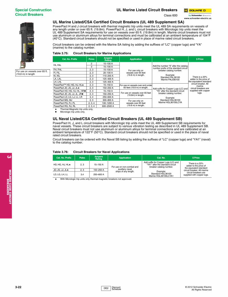
3M
OLD
ED
CA
SE
CIR
CU
IT
BR
EA
KE
RS
Special Construction Circuit Breakers
UL Marine Listed Circuit BreakersClass 600
www.schneider-electric.us
UL Marine Listed/CSA Certified Circuit Breakers (UL 489 Supplement SA)PowerPact H and J circuit breakers with thermal magnetic trip units meet the UL 489 SA requirements on vessels of any length under or over 65 ft. (19.8m). PowerPact H, J, and L circuit breakers with Micrologic trip units meet the UL 489 Supplement SA requirements for use on vessels over 65 ft. (19.8m) in length. Marine circuit breakers must not use aluminum or aluminum alloys for terminal connections and must be calibrated at an ambient temperature of 104°F (40°C). Standard circuit breakers should not be specified or used in place of marine rated circuit breakers.
Circuit breakers can be ordered with the Marine SA listing by adding the suffixes of “LC” (copper lugs) and “YA” (marine) to the catalog number.
a Thermal-Magnetic trip units only.b Micrologic trip units only.
UL Naval Listed/CSA Certified Circuit Breakers (UL 489 Supplement SB)PowerPact H, J, and L circuit breakers with Micrologic trip units meet the UL 489 Supplement SB requirements for naval vessels. These circuit breakers are subject to various vibration testing as described in UL 489 Supplement SB. Naval circuit breakers must not use aluminum or aluminum alloys for terminal connections and are calibrated at an ambient temperature of 122°F (50°C). Standard circuit breakers should not be specified or used in the place of naval rated circuit breakers.Circuit breakers can be ordered with the Naval SB listing by adding the suffixes of “LC” (copper lugs) and “YA1” (naval) to the catalog number.
a With Micrologic trip units only thermal-magnetic breakers not approved.
Table 3.75: Circuit Breakers for Marine Applications
Cat. No. Prefix Poles AmpereRating Application Cat. No. $ Price
FA, FAL2 15–100 A
For use only onvessels over 65 feet(19.8 m) in length.
Add the number “9’’ after the catalognumber prefix of the standard circuit
breaker catalog number.
Example:Standard FAL36100Marine FAL936100
There is a 20%adder to the price of
the equivalent standardcircuit breaker. All
marinecircuit breakers are
supplied with copper lugs.
3 15–100 AFH, FHL 2, 3 15–100 AFI, FIL 2, 3 20–100 AKI, KIL 2, 3 110–250 ALA, LAL 2, 3 125–400 ALH, LHL 2, 3 125–400 APowerPact™ HD, HG, HJ, HLa 2, 3 15–150 A For use on vessels over and under
65 feet (19.8 m) in length. Add suffix for Copper Lugs (LC) and “YA’’ after the standard circuit
breaker catalog number.
Example:Standard HGL36100
Marine HGL36100LCYA
PowerPact JD, JG, JJ, JLa 2, 3 150–250 APowerPact HD, HG, HJ, HL, HRb 2, 3 15–150 A
For use on vessels over 65 feet (19.8m) in length.PowerPact JD, JG, JJ, JL, JRb 2, 3 150–250 A
PowerPact LD, LG, LJ, LL, LR 3, 4 250–600 APowerPact MG, MJ 2, 3 300–800 A For use only on
vessels over 65 feet(19.8 m) in length.
PowerPact PG, PJ, PL 2, 3, 4 100–1200 APowerPact RG, RJ, RL 2, 3, 4 600–2500 A
Table 3.76: Circuit Breakers for Navel Applications
Cat. No. Prefix Poles AmpereRating Application Cat. No. $ Price
HD, HG, HJ, HLa 2, 3 15–150 AFor use on non-combat and
auxiliary navalships of any length.
Add suffix for Copper Lugs (LC) and “YA1’’ after the standard circuit
breaker catalog number.
Example:Standard HGL36100
Marine HGL36100LCYA1
There is a 20%adder to the price of
the equivalent standardcircuit breaker. All marine
circuit breakers aresupplied with copper lugs.
JD, JG, JJ, JLa 2, 3 150–250 A
LD, LG, LH, LL 3,4 250–600 A
For use on vessels over 65 ft. (19,8 m) in length
3-22 © 2012 Schneider ElectricAll Rights Reserved
DE2 Discount Schedule

© 2012 Schneider ElectricAll Rights Reserved
Circuit Breaker Accessories
PowerPact™ Circuit Breakers Electrical AccessoriesClass 612 / Refer to Catalog 0616CT0801
3M
OL
DE
D C
AS
E C
IRC
UIT
B
RE
AK
ER
S
www.schneider-electric.us
Table 3.77: Electrical Accessories
Accessory Description Rated Voltage
G-Frame D-Frame
Field-InstallableCat. No.
$ PriceFactory-Installed
Cat. Suffix
Field-InstallableCat. No.
$ Price $ Price
Auxiliary and Alarm Switches (OF, SD, SDE)
Provides circuit breaker contact status.
Note: The location of the accessory in the circuit breaker determines its function.
Standard Min Load =
10mA with 24V
1 auxiliary switch (OF) 1a1b AAC 297.00 AA S29450 297.00 297.002 auxiliary switch (OF) 2a2b — — AB 2x S29450 594.00 594.003 auxiliary switch (OF) 3a3b — — AC 3x S29450 891.00 891.00Alarm Switch (SD) 1a1b AAC 297.00 BC S29450 297.00 297.00Overcurrent trip switch (SDE) 1a1b — — BD S29450 297.00 297.00
Consisting of:OF Switch — — — — — —
SDE Adapter — — — — — —Alarm switch and Overcurrent trip switch — — BE 2x S29450 594.00 594.00
Consisting of:OF Switch — — — — — —
SDE Adapter — — — — — —Auxiliary Switch/Alarm Switch/Adapter (OF/SD/SDE) Kit — — — — — 297.00
Low LevelMin Load =
1mA with 24V
One auxiliary switch (OF) 1a1b — — AE S29452 372.00 372.00Two auxiliary switches (OF) 2a2b — — AF 2x S29452 744.00 744.003 auxiliary switches (OF) 3a3b — — AG 3x S29452 1116.00 1116.00Alarm Switch (SD) 1a1b — — BH S29452 372.00 372.00Overcurrent trip switch (SDE) 1a1b — — BJ S29452 372.00 372.00
Consisting of:OF Switch — — — — — —
SDE Adapter — — — — — —Alarm switch and Overcurrent trip switch — — BK 2x S29452 744.00 744.00
Consisting of:OF Switch — — — — — —
SDE Adapterd — — — — — —
Shunt Trip (MX)
Trips the circuit breaker from a remote location by means of a trip coil energized from a separate supply voltage circuit.
AC
24 —
717.00
SK S29384
717.00 755.00
48 — SL S29385120 GSA — —
110/130 — SA S29386208 GSB — —240 GSC — —
200/250 — — —277 GSD — —
208/277 — SD S29387480 GSH — —
380/480 — SH S29388525/600 — SJ S29389
DC
12 —
717.00
SN S29382
717.00 755.00
24 GSO SO S2939030 — SU S2939148 GSP SP S2939260 — SV S29383125 GSR SR S29393250 GSS SS S29394
Undervoltage Trip
Instantaneously opens the circuit breaker when the under-voltage trip supply voltage drops to a value between 35% and 70% of its rated voltage. Closing is allowed when the supply voltage of the undervoltage trip reaches 85% of rated voltage.
AC
24 —
717.00
UK S29404
717.00 755.00
48 — UL S29405120 GUA — —
110/130 — UA S29406208 GUB — —240 GUC — —
200/250 — — —277 GUD — —
208/277 — UD S29407480 GUH — —
380/480 — UH S29408525/600 — UJ S29409
DC
12 —
717.00
UN S29402
717.00 755.00
24 GUO UO S2941030 — UU S2941148 GUP UP S2941260 — UV S29403125 GUR UR S29413250 GUS US S29414
a Field-installable kit includes time delay module only. Order undervoltage trip separately.b Discount schedule DE2F.c P-frame drawout circuit breaker only.d SDE Adapter used for H- and J-frame only.
G-FrameD-Frame
G-FrameD-Frame
G-FrameD-Frame
3-23
DE2 DE2F Discount Schedule
3M
OLD
ED
CA
SE
CIR
CU
IT
BR
EA
KE
RS
Circuit Breaker Accessories
Factory-Installed Accessories
www.schneider-electric.us
Factory-Installed Electrical Accessories Electrical accessories are available on all molded case circuit breakers except FY and QOM1 circuit breakers.• Alarm switch is the only accessory available for the 1-pole FA circuit breaker.• Combination accessories may be ordered by description, i.e., 1021 and 1212.• All AC electrical accessories shown below are rated for 50/60 Hz.• Add 20% to accessory price for each field-installable accessory that is factory-installed.• See page 3-25 for field-installable accessories. See Digest page 7-35 for PowerPact™ circuit breaker accessories.
Table 3.78: Factory-Installed Accessories for Thermal-Magnetic Circuit Breakers
Accessory Description Rated Voltage
Coil Burdena Suffix $ Price
Adder
Shunt Trip
Trips the circuit breaker from a remote location by means of a trip coil energized from a separate circuit. A 120 V shunt trip will operate at 55% or more of rated voltage. All other shunt trips will operate at 75% or more of rated voltage.
Application
• For use with momentary or maintained push button.• Sure Trip Capacitor Unit requires 48 Vdc shunt trip.• Leads: (2) Black.18 AWG Cu.
24 Vac 21 VA -1042b 755.00120 Vac 24 VA -1021c 755.00208 Vac 107 VA -1021 755.00240 Vac 154 VA -1021 755.00277 Vac 14 VA -1037b 755.00480 Vac 45 VA -1037b 755.0024 Vdc 36 VA -1027 755.0048 Vdc 36 VA -1028 755.00125 Vdc 44 VA -1029 755.00250 Vdc 15 VA -1030d 755.00
Ground-Fault
Shunt Trip
Trips the circuit breaker electrically using the signal from a Micrologic™ Ground-Fault Module.
Application
• For use only with obsolete GP Ground-Censor™ system or add on ground-fault module.• Leads: (2) Orange 18 AWG Cu.
— — -Gd 755.00
Undervoltage Trip (UVR)
Trips the circuit breaker electrically when a control circuit falls below 35 to 70% of nominal (not field adjustable). Picks up at 35–85% of nominal voltage.
Application
• UVR must be energized in order to close the circuit breaker.• Leads: (2) Brown 18 AWG Cu leads.
24 Vac120 Vac240 Vac24 Vdc48 Vdc
5 VA8 VA8 VA2 VA3 VA
-1143d-1121-1124-1127-1128
755.00755.00755.00755.00755.00
Time Delay Unit
Provides adjustable time delay for UVR of 0.1 to 0.6 second before circuit breaker trips.
Application
• For use only with -1121 UV trip.• Adjustable time delay (0.1 to 0.6 second).• I-Line unit requires 1.5 in. (38 mm) of mounting space.• Leads: (2) Brown 18 AWG Cu and (2) Black/White 18 AWG Cu.
120 Vac
Cat. No.
Unit Mt. I-Line™
690UVTD 690UVTDI 1941.00
Auxiliary Switches
Monitors circuit breaker contact status and provides a remote signal indicating the circuit breaker contacts are OPEN or CLOSED.
Application
• Max. Load = FA, FH, FI, LC, LE, LI, LX, LXI.10 A @ 125–250 Vac, ¼ hp @ 125–250 Vac, 5 A @ 30 Vdc
• Leads: Yellow for “A’’, Blue for “B’’, Striped for common 18 AWG Cu.
See load info. in
App. textat left
See load info. in
App. textat left
1A/1B -1212 312.002A/2B -1352 623.003A/3B -1364e 800.00
Alarm Switches
Used with control circuits and actuated only when the circuit breaker has tripped. Standard construction includes a normally-open contact.
Application
• Max. Load = 10 A @ 125–250 Vac• Max. Load = 15 A @ 30 Vdc• Leads: (2) Red 18 AWG Cu.
1A
1A
1B
1B
250 Vac
28 Vdc
250 Vac
48 Vdc
Seeload
info. inApp.text
at left
-2100
-2100
-2103
-2103
312.00
312.00
312.00
312.00
a Coil burden values do not apply to LC, LE, LI, LX and LXI. Consult Field Sales office for more information.b Not available on FI or KI circuit breakers.c LC, LE, LI, LX, and LXI circuit breakers operate at 75% or more of rated voltage.d Not available on LC, LE, LI, LX, LXI circuit breakers.e Not available in FA, FC, FH, FI and KI circuit breakers.
Circuit Breaker Open or Closed
1A Alarm SwitchConfiguration
Color Code: Red Leads
Circuit Breaker Tripped
Circuit Breaker Tripped
1B Alarm SwitchConfiguration
Color Code: Red Leads
Circuit Breaker Open or Closed
1A/1B
Circuit Breaker Closed
A B
Circuit Breaker Open or Tripped
A B
Auxiliary SwitchContact Configuration
Color Code:"A" Contact - Yellow Leads"B" Contact - Blue LeadsCommon-Striped Leads
Undervoltage TripWiring Diagram
Brown
Brown
Brown Wires To BeConnected ToControl Power
UVR
Shunt TripWiring Diagram
Black
Black
Black Wires To BeConnected ToControl Power
ShuntTrip
690UVTD Wiring Diagram
3-24 © 2012 Schneider ElectricAll Rights Reserved
DE2 Discount Schedule

© 2012 Schneider ElectricAll Rights Reserved
Circuit Breaker Accessories
Field-Installable Accessories
3M
OL
DE
D C
AS
E C
IRC
UIT
B
RE
AK
ER
S
www.schneider-electric.us
Field-Installable Electrical AccessoriesComplete field-installable accessory catalog number by inserting suffix from 3-24 between the parentheses in the catalog numbers shown in the table below. (Example: LA11212) See 3-24 for accessory pricing; add 20% to factory-install field-installable devices.
Table 3.79: Field-Installable Accessories for Thermal-Magnetic and Electronic Trip Circuit Breakers
Circuit Breaker Shunt Trip Ground-FaultShunt Tripa Undervoltage Trip Auxiliary Switches Alarm Switch
Miniature Circuit Breakers, EH and EH-PL
Factory-Installed Only Not Available Not Available Factory-Installed
OnlyFactory-Installed
Only
FA, FH, FI, KI Factory-Installed Only
Factory-Installed Only
Factory-Installed Only
Factory-Installed Only
Factory-Installed Only
LA, LH Series 4b LA1( ) LA1G LA1 ( ) LA1( ) Factory-Installed
Only Right Pole
Q4 LA1( ) LA1G LA1 ( ) LA1( ) Factory-Installed Only Right Pole
LC, LE, LI, LX, LXI LC1( ) LC1G LC1 ( ) LC1( ) Factory-Installed Only
a Used with obsolete GP Ground-Censor™ system or add-on ground-fault modules.b With LA and LH top-feed circuit breakers (suffix MT, I-Line jaws on OFF end) all accessories must be factory
installed.
Table 3.80: Accessory Mounting Locations
LA, LH, Q4 Series 4 circuit breakers or newer = Field-installable accessoriesLC, LI, LX, LXI circuit breakers = Field-installable accessoriesBoth accessory ports will accept shunt trips, UVRs and auxiliary switches. Alarm switches are factory installable only (right pole). Maximum of one device per port.
1A/1B
Circuit Breaker Closed
A B
Circuit Breaker Open or Tripped
A B
Auxiliary SwitchContact Configuration
Color Code:"A" Contact - Yellow Leads"B" Contact - Blue LeadsCommon-Striped Leads
Circuit Breaker Open or Closed
1A Alarm SwitchConfiguration
Color Code: Red Leads
Circuit Breaker Tripped
Circuit Breaker Tripped
1B Alarm SwitchConfiguration
Color Code: Red Leads
Circuit Breaker Open or Closed
Undervoltage TripWiring Diagram
Brown
Brown
Brown Wires To BeConnected ToControl Power
UVR
Shunt TripWiring Diagram
Black
Black
Black Wires To BeConnected ToControl Power
ShuntTrip
L R
3-25
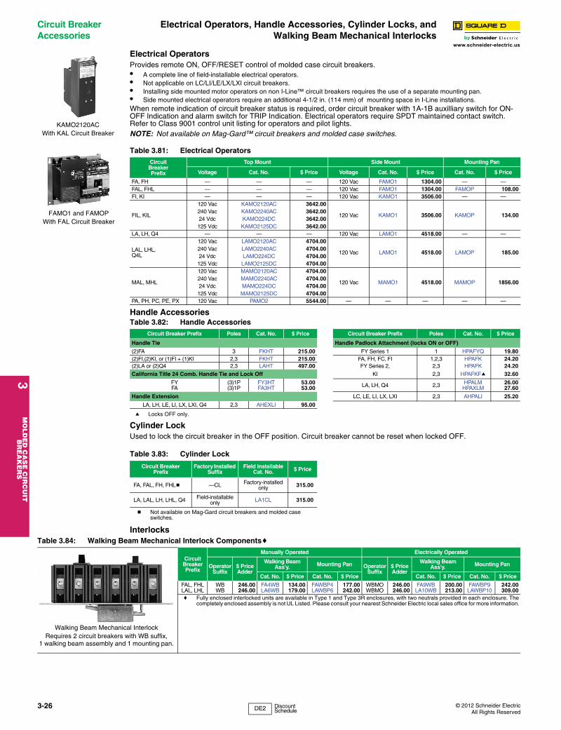
3M
OLD
ED
CA
SE
CIR
CU
IT
BR
EA
KE
RS
Circuit Breaker Accessories
Electrical Operators, Handle Accessories, Cylinder Locks, andWalking Beam Mechanical Interlocks
www.schneider-electric.us
Electrical OperatorsProvides remote ON, OFF/RESET control of molded case circuit breakers.• A complete line of field-installable electrical operators.• Not applicable on LC/LI/LE/LX/LXI circuit breakers.• Installing side mounted motor operators on non I-Line™ circuit breakers requires the use of a separate mounting pan.• Side mounted electrical operators require an additional 4-1/2 in. (114 mm) of mounting space in I-Line installations.When remote indication of circuit breaker status is required, order circuit breaker with 1A-1B auxilliary switch for ON-OFF Indication and alarm switch for TRIP Indication. Electrical operators require SPDT maintained contact switch. Refer to Class 9001 control unit listing for operators and pilot lights.NOTE: Not available on Mag-Gard™ circuit breakers and molded case switches.
Handle Accessories
a Locks OFF only.
Cylinder LockUsed to lock the circuit breaker in the OFF position. Circuit breaker cannot be reset when locked OFF.
Interlocks
Table 3.81: Electrical OperatorsCircuit
BreakerPrefix
Top Mount Side Mount Mounting Pan
Voltage Cat. No. $ Price Voltage Cat. No. $ Price Cat. No. $ Price
FA, FH — — — 120 Vac FAMO1 1304.00 — —FAL, FHL — — — 120 Vac FAMO1 1304.00 FAMOP 108.00FI, KI — — — 120 Vac KAMO1 3506.00 — —
FIL, KIL
120 Vac KAMO2120AC 3642.00
120 Vac KAMO1 3506.00 KAMOP 134.00240 Vac KAMO2240AC 3642.0024 Vdc KAMO224DC 3642.00125 Vdc KAMO2125DC 3642.00
LA, LH, Q4 — — — 120 Vac LAMO1 4518.00 — —
LAL, LHL,Q4L
120 Vac LAMO2120AC 4704.00
120 Vac LAMO1 4518.00 LAMOP 185.00240 Vac LAMO2240AC 4704.0024 Vdc LAMO224DC 4704.00125 Vdc LAMO2125DC 4704.00
MAL, MHL
120 Vac MAMO2120AC 4704.00
120 Vac MAMO1 4518.00 MAMOP 1856.00240 Vac MAMO2240AC 4704.0024 Vdc MAMO224DC 4704.00125 Vdc MAMO2125DC 4704.00
PA, PH, PC, PE, PX 120 Vac PAMO2 5544.00 — — — — —
Table 3.82: Handle AccessoriesCircuit Breaker Prefix Poles Cat. No. $ Price Circuit Breaker Prefix Poles Cat. No. $ Price
Handle Tie Handle Padlock Attachment (locks ON or OFF)
(2)FA 3 FKHT 215.00 FY Series 1 1 HPAFYQ 19.80(2)FI,(2)KI, or (1)FI + (1)KI 2,3 FKHT 215.00 FA, FH, FC, FI 1,2,3 HPAFK 24.20(2)LA or (2)Q4 2,3 LAHT 497.00 FY Series 2, 2,3 HPAFK 24.20California Title 24 Comb. Handle Tie and Lock Off KI 2,3 HPAFKFa 32.60
FYFA
(3)1P(3)1P
FY3HTFA3HT
53.0053.00 LA, LH, Q4 2,3 HPALM
HPAXLM26.0027.60
Handle Extension LC, LE, LI, LX, LXI 2,3 AHPALI 25.20
LA, LH, LE, LI, LX, LXI, Q4 2,3 AHEXLI 95.00
Table 3.83: Cylinder Lock
Circuit BreakerPrefix
Factory Installed Suffix
Field Installable Cat. No. $ Price
FA, FAL, FH, FHLb —CL Factory-installed only 315.00
LA, LAL, LH, LHL, Q4 Field-installableonly LA1CL 315.00
b Not available on Mag-Gard circuit breakers and molded case switches.
KAMO2120ACWith KAL Circuit Breaker
FAMO1 and FAMOPWith FAL Circuit Breaker
Table 3.84: Walking Beam Mechanical Interlock Componentsc
Circuit BreakerPrefix
Manually Operated Electrically Operated
OperatorSuffix
$ PriceAdder
Walking Beam Ass'y. Mounting Pan Operator
Suffix$ PriceAdder
Walking Beam Ass'y. Mounting Pan
Cat. No. $ Price Cat. No. $ Price Cat. No. $ Price Cat. No. $ Price
FAL, FHLLAL, LHL
WBWB
246.00246.00
FA4WBLA6WB
134.00179.00
FAWBP4LAWBP6
177.00242.00
WBMOWBMO
246.00246.00
FA9WBLA10WB
200.00213.00
FAWBP9LAWBP10
242.00309.00
c Fully enclosed interlocked units are available in Type 1 and Type 3R enclosures, with two neutrals provided in each enclosure. The completely enclosed assembly is not UL Listed. Please consult your nearest Schneider Electric local sales office for more information.
Walking Beam Mechanical Interlock Requires 2 circuit breakers with WB suffix,
1 walking beam assembly and 1 mounting pan.
3-26 © 2012 Schneider ElectricAll Rights Reserved
DE2 Discount Schedule
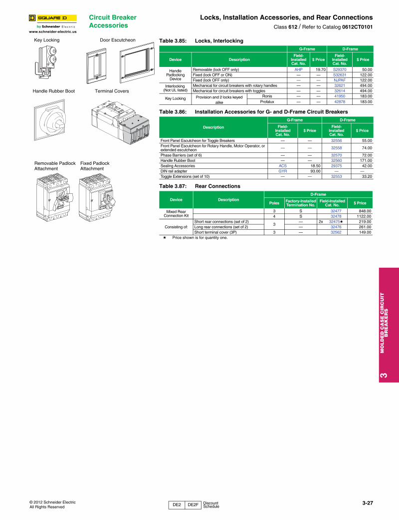
© 2012 Schneider ElectricAll Rights Reserved
Circuit Breaker Accessories
Locks, Installation Accessories, and Rear ConnectionsClass 612 / Refer to Catalog 0612CT0101
3M
OL
DE
D C
AS
E C
IRC
UIT
B
RE
AK
ER
S
www.schneider-electric.us
Table 3.85: Locks, InterlockingG-Frame D-Frame
Device DescriptionField-
InstalledCat. No.
$ PriceField-
InstalledCat. No.
$ Price
HandlePadlocking
Device
Removable (lock OFF only) AHP 19.70 S29370 50.00Fixed (lock OFF or ON) — — S32631 122.00Fixed (lock OFF only) — — NJPAF 122.00
Interlocking (Not UL listed)
Mechanical for circuit breakers with rotary handles — — 32621 494.00Mechanical for circuit breakers with toggles — — 32614 494.00
Key Locking Provision and 2 locks keyed alike
Ronis — — 41950 183.00Profalux — — 42878 183.00
Table 3.86: Installation Accessories for G- and D-Frame Circuit Breakers
Description
G-Frame D-Frame
Field-InstalledCat. No.
$ PriceField-
InstalledCat. No.
$ Price
Front Panel Escutcheon for Toggle Breakers — — 32556 55.00Front Panel Escutcheon for Rotary Handle, Motor Operator, or extended escutcheon — — 32558 74.00
Phase Barriers (set of 6) — — 32570 72.00Handle Rubber Boot — — 32560 171.00Sealing Accessories ACS 18.50 29375 42.00DIN rail adapter GYR 93.00 — —Toggle Extensions (set of 10) — — 32553 33.20
Table 3.87: Rear Connections
Device DescriptionD-Frame
Poles Factory-Installed Termination No.
Field-InstalledCat. No. $ Price
Mixed RearConnection Kit
3 S 32477 848.004 S 32478 1122.00
Consisting of:Short rear connections (set of 2)
3— 2x 32475d 219.00
Long rear connections (set of 2) — 32476 261.00Short terminal cover (3P) 3 — 32562 149.00
d Price shown is for quantity one.
Handle Rubber Boot
Door Escutcheon
Terminal Covers
Removable Padlock Attachment
Fixed Padlock Attachment
Key Locking
3-27
DE2 DE2F Discount Schedule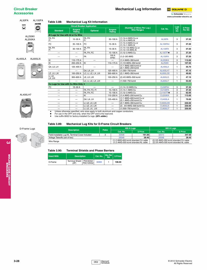
3M
OLD
ED
CA
SE
CIR
CU
IT
BR
EA
KE
RS
Circuit Breaker Accessories
Mechanical Lug Information
www.schneider-electric.us
a Unless otherwise specified, wire sizes apply to both aluminum and copper conductors.b For use in the OFF end only, when the OFF end is the load end.c Use suffix 8002 for factory-installed Cu lugs. (20% adder.)
Table 3.88: Mechanical Lug Kit InformationCircuit Breaker Application
(Number of Wires Per Lug )Wire Rangea Cat. No.
LugsPer Kit
$ PricePer KitStandard Ampere
Rating Optional AmpereRating
Al Lugs for Use with Al or Cu Wire
FA, FHFI 15–30 A FA, FH
FI 35–100 A (1) 14–4 AWG Cu or(1) 12–4 AWG Al AL50FA 3 37.20
FC 35–100 A FC 15–30 A (1) 14–3 AWG Cu or(1) 12–1 AWG Al AL100FA4 3 37.20
FA, FHFI 35–100 A FA, FH
FI 15–30 A (1) 14–1/0 AWG Cu or(1) 12–1/0 AWG Al AL100FA 3 37.20
— — FA, FH, FC 15–100 A (1) 12–3 AWG Cu AL100TFb 3 37.20
— — FA 150 A(only) (1) 2–3/0 AWG AL150FA 3 37.20
KI 110–175 A — — (1) 4 AWG–350 kcmil AL250KA 3 113.00KI 200–250 A KI 110–175 A (1) 1/0 AWG–350 kcmil AL250KI 3 107.00
Q4, LA, LH 125–400 A — — (1) 1 AWG–600 kcmil or(2) 1 AWG–250 kcmil AL400LA 1 35.70
— — Q4, LA, LH 125–400 A (1) 350–750 kcmil AL400LH7 1 47.10LE, LX, LXI 100–250 A LC, LI, LE, LX, LXI 300–600 A (2) 1 AWG–350 kcmil AL600LI35 1 49.60LI, LE, LX, LXI 300–600 A LE, LX, LXI 100–250 A (2) 4/0 AWG–500 kcmil AL600LI5 1 47.10
— — LC, LI, LE, LX, LXI — (1) 500–750 kcmil AL600LI7 1 53.00
Cu Lugs for Use with Cu Wire Only c
FC 15–30 A — — (1) 14–10 AWG Cu CU30FA4 3 37.20— — FA, FH, FC, FI 15–100 A (1) 14–1 AWG Cu CU100FA 3 37.20— — FA, FH, FC 15–100 A (1) 12–3 AWG Cu CU100TFb 3 62.00— — KI 110–250 A (1) 4 AWG–250 kcmil Cu CU250KA 3 113.00
— — Q4, LA, LH 125–400 A (1) 1 AWG–600 kcmil Cu or(2) 1 AWG–250 kcmil Cu CU400LA 1 70.00
— — LI, LE, LX, LXI — (2) 1 AWG–350 kcmil Cu CU600LI35 1 230.00— — LI, LE, LX, LXI — (2) .4/0 AWG–500 kcmil Cu CU600LI5 1 230.00— — LI, LE, LX, LXI — (1) 500–750 kcmil Cu CU600LI7 1 230.00
Table 3.89: Mechanical Lug Kits for D-Frame Circuit Breakers
Description Poles400 A Lugs 600 A Lugs
Cat. No. $ Price Cat. No. $ Price
Field-Installable Lug Kit, Terminal Cover Included 3 32508 191.00 32510 347.00Voltage Takeoffs (set of two) 29348 28.40 29348 28.40
Wire Range (1) 2 AWG-600 kcmil stranded CU cable(1) 2 AWG-500 kcmil stranded AL cable
(2) 2/0 AWG-350 kcmil stranded CU cable(2) 2/0 AWG-500 kcmil stranded AL cable
Table 3.90: Terminal Shields and Phase Barriers
Used With Description Cat. No. Qty Per Kit $ Price
D-Frame Terminal Shield (3P)
PDC5DG2PDC12DG2 36965 1 108.00
AL50FA
AL250KIAL250KA
AL100FA
AL400LA AL600LI5
AL400LH7
D-Frame Lugs
3-28 © 2012 Schneider ElectricAll Rights Reserved
DE2 Discount Schedule

© 2012 Schneider ElectricAll Rights Reserved
Circuit Breaker Accessories
Compression Lug and Power Distribution Connectors
3M
OL
DE
D C
AS
E C
IRC
UIT
B
RE
AK
ER
S
www.schneider-electric.us
Compression Lug Kits
a See instruction bulletins for recommended tools.b These lug kits cannot be used on I-Line™ circuit breakers.c Unless otherwise specified, wire sizes apply to both aluminum and copper conductors.d All P-frame circuit breakers require terminal pads for mounting lugs of any type.
Power Distribution Connectors (PDC) for Circuit Breakers—for Field Replacement of Mechanical LugsCan be used for multiple load connections on one circuit breaker. Use in place of standard distribution blocks to save space and time.
Field-installable kits, including tin-plated aluminum connectors and all necessary mounting hardware are available for Square D FA, LA and Q4-frame molded case circuit breakers.Connectors are UL Listed:• For use on load end of circuit breaker only• For use in UL508 Industrial Control applications only• For use in UL 1995/CSA C22.2 No. 236 heating and cooling equipment• For copper wire only
e Not for use with I-Line circuit breakers.f When using fine stranded wire, increased cross sectional area may cause maximum wire size to be reduced.g OFF end only when OFF end is the load end.
h Kit includes long terminal shield, which adds 1.65 inches to standard lug with short terminal shield.
Table 3.91: Field-installable Compression Lug KitsaCircuit Breaker
Type Wire Rangec Dimension A (In)
Max. LugsPer Terminal Cat. No. Lug Qty.
Per Kit$ Price Per
Kit
Aluminum Compression Lug Kits
FA, FH, FC, FI 8–1/0 AWG 1.3 1 VC100FA 3 175.00
KI4 AWG–300 kcmil 1.5 1 VC250KA3 3 255.00250–350 kcmil 1.5 1 VC250KA35 3 194.00
LA, LH, Q4
250–350 kcmil 1.25 2 VC400LA35 2 194.004 AWG–300 kcmil 1.0 2 VC400LA3 2 202.002/0 AWG–500 kcmil 2.2 1 VC400LA5 1 166.00500–750 kcmil 2.5 1 VC400LA7 1 198.00
LI, LE, LX, LXI b4 AWG–300 kcmil 1.05 2 VC600LI3 2 295.002/0 AWG–500 kcmil 3.20 2 VC600LI5 2 308.00500–750 kcmil 3.45 1 VC600LI7 1 311.00
Copper Compression Lug Kits
FA, FH, FC, FI 6–1/0 AWG Cu 1.4 1 CVC100FA 3 156.00KI 2/0 AWG–300 kcmil Cu 1.5 1 CVC250KA3 3 301.00
LA, LH, Q42/0 AWG–300 kcmil Cu 1.3 2 CVC400LA3 2 271.00250–500 kcmil Cu 2.3 1 CVC400LA5 1 118.00
LI, LE, LX, LXI b 250–500 kcmil Cu 3.20 2 CVC600LI5 2 491.00
Compression Lug Kits for D-Frame Circuit Breakers
Not Available
Table 3.92: PDC Lugs
Use With Circuit Breakere
Circuit Breaker Ampere Rating
Wires Per Terminal& Wire Rangef
CuCat. No. Lug Quantity Per Kit Dimension
A (i.)$ Price Per
Kit
FAL, FHL, FCLg 15–100 A(6) 14–6 AWG PDC6FA6 3 1.0 92.00(3) 14–2 AWG PDC3FA2 3 1.2 92.00
LAL, LHL, Q4L 125–400 A
(6) 12–2/0 AWG PDC6LA20 1 2.25 182.00(12) 14–4 AWG PDC12LA4 1 1.25 129.00(3) 14–2 AWG
(1) 2 AWG–250 kcmil PDC4LA250 1 2.0 129.00
Table 3.93: Power Distribution Connectors for D-Frame Circuit Breakers
Use with Circuit Breaker Type
Circuit BreakerAmpere Rating
Wires Per Terminal & Wire Range Dimension A (in.) Cat. No. Quantity Per Kit $ Price Per Kit
DG, DJ, DL150–600 (3) 14–2 AWG and (2) 14–2/0 AWG 1.28h PDC5DG20 3 387.00150–600 (12) 14–4 AWG 1.31h PDC12DG4 3 387.00
Extremityof
Molded Casew/Mechanical
Lugs
“A” See Table
Crimp lug orpower distribution connectors
extension past end ofcircuit breaker “A” See Table
CVC100FAVC250KA3
VC400LA7
VC1200NE5
VC400LA7
CVC600MA5
PDC12LA4
3-29
DE2 Discount Schedule
3M
OLD
ED
CA
SE
CIR
CU
IT
BR
EA
KE
RS
Circuit Breaker Accessories
PowerPact™ Circuit Breakers Miscellaneous AccessoriesClass 612 / Refer to Catalog 0612CT0101
www.schneider-electric.us
a Short lug shields provide IP20 protection for mechanical lugs and are compatible with control wire terminals.b J-frame terminal shield is not compatible with the YA250J35 compression terminal.
c DE5A Discount Schedule
Table 3.94: Bus Bar Connections Hardware for D-Frame Circuit BreakersFrame Description Term. No. Poles Cat. No. $ Price
D-FrameSet of 3 terminal screws and washers for one side
F3 36966 23.70
Set of 4 terminal screws and washers for one side 4 36967 31.50
Table 3.95: Terminal Shields and Phase Barriers
Used With Description Dimension B (in.) Cat. No. Qty Per
Kit $ Price
G-Frame Terminal Shield (3P) — — — GYT 1 75.00
D-Frame Terminal Shield (3P)
PDC5DG2PDC12DG2 — — 36965 1 108.00
Table 3.96: Miscellaneous D-Frame Circuit Breaker Accessories
Accessory Description Field-InstalledCat. No, $ Price
External Neutral Sensor
150 A Neutral Sensor 36950 806.00250 A Neutral Sensor 36951 806.00400 A Neutral Sensor 36952 806.00600 A Neutral Sensor 36953 806.00
Spare Parts 100 Identification Labels 29314 119.00
Test KitsMini test kit (battery not included) 43362 884.00Portable test kit 55391c 16365.00
Table 3.97: Motor Operators for D-Frame Circuit Breakers
Description Rated Voltage
Factory InstalledCat. No. Suffix
Field-InstalledCat. No, $ Price
Standard motor for electrically-operated circuit breakers
AC
48/60 ML 32839
3395.00
110/130 MA 32840208/277 MD 22841220/240 MC —380/415 MF 32842380/485 MH —440/480 MH 32847
DC
24/30 MO 32843
3545.0048/60 MP 32844
110/130 MR 32845250 MS 32846
Locking DeviceMounting Hardware — 32649 58.00
Ronis lock — 41940 146.00Profalux lock — 42888 146.00
Operations Counter — 32648 225.00
Mini Test Kit Portable Test Kit
Motor Operator
3-30 © 2012 Schneider ElectricAll Rights Reserved
DE2 Discount Schedule

© 2012 Schneider ElectricAll Rights Reserved
Electronic Products Neutral Current Transformers andMicrologic™ Series B Trip Unit Accessories
3M
OL
DE
D C
AS
E C
IRC
UIT
B
RE
AK
ER
S
www.schneider-electric.us
Complying with NEC®
The National Electrical Code, Section 240-6(c) exception allows conductor ampere ratings equal to the selected long-time pick-up setting. Square D offers the seals below to restrict access to trip unit once settings are selected.
a Required for Micrologic to communicate with PowerLogic™ system.
Table 3.98: Neutral Current Transformers
Cat. No. $ Price Sensor Where Used
LE25CT2LE4CT2LE6CT2
588.00588.00588.00
250 A400 A600 A
LXL, LEL, LXIL
Table 3.99: Electronic Trip Indicator and Current Meter Field-installable Kits
Device Cat. No. Included With Circuit Breaker Optional $ Price
Local Trip Indicator Kit ALTI — LXL, LXIL 1461.00
Local Current Meter Kit/Trip Indicator ALAM LEL LXL, LXIL 2286.00
Table 3.100: Interchangeable Rating Plug Kits for all Circuit Breakers with Micrologic Series B Trip System
Cat. No. Sensor Multiplier Value $ Price
ARP040 0.400 297.00ARP050 0.500 297.00ARP056 0.563 297.00ARP058 0.583 297.00ARP060 0.600 297.00ARP063 0.625 297.00ARP067 0.667 297.00ARP070 0.700 297.00ARP075 0.750 297.00ARP080 0.800 297.00ARP083 0.833 297.00ARP088 0.875 297.00ARP090 0.900 297.00ARP100 1.000 297.00
Table 3.101: Trip Unit Seals
Description Cat. No. Package Quantity $ Price
Trip Unit Seal TUSEAL 100 102.00
Table 3.102: Communication Adapter
Description Cat. No. $ Price
Communication Adapter CIM3Fa 465.00
Table 3.103: Test Equipment for Circuit Breakers with Micrologic Series B Trip Systems
Description Cat. No. $ Price
Universal Test Set (includes test module for Full-function and Standard-function LEL, LXL, LXIL) UTS3 14022.00Test Module for Full-function and Standard-function LEL, LXL, LXIL. (For use with existing CBTU1 or UTS3 test set.) CBTMB 2349.00
Replacement ribbon cable and rating plug adapter for CBTMB CBTMBRK 627.00Long-time and ground-fault Memory Reset Module (Series B Electronics) MTMB 381.00
Combination Local Current Meter and Trip Indicator
Electronic Trip Unit with Seals Installed to Restrict Access
CIM3F Communication Adapter
Universal Test Set
3-31
DE2 Discount Schedule
3M
OLD
ED
CA
SE
CIR
CU
IT
BR
EA
KE
RS
Electronic Products Restraint Interface Module
www.schneider-electric.us
S48890 and S48895 Restraint Interface Modules
The Restraint Interface Module (RIM) is used to allow zone-selective Interlocking communications between circuit breakers with Micrologic™ Series B trip units or Micrologic™ #.Ox trip units, Compact™ STR53 trip units, Masterpact™ STR58 trip units, Federal Pioneer USRC and USRCM trip units, and Square D GC series ground-fault relays.Upstream circuit breakers with Micrologic 3.0A, 5.0A 5.0P, 5.0H, 6.0A, 6.0P, and 6.0H trip units can receive up to 15 input signals without requiring a restraint interface module. If the number of input signals exceeds 15, then a RIM is required. Contact your local Sales Office for RIM requirements.
The restraint interface module operates on either 120 Vac/24 Vdc, or 240 Vac/24 Vdc, 50/50 Hz.NOTE: The maximum distance between devices is
1000 ft. (305 m)
Table 3.104: RIM Requirements
Note: R=RIM module is required to restrain any devices.Numerical References=Maximum number of upstream circuit breakers which can be restrained without requiring a RIM module.
Mic
rolo
gic
#.0x
Tri
p U
nits
Sq
uare
D M
icro
logi
cS
erie
s B
Tri
p U
nits
Squ
are
D G
C-1
00 G
roun
d-Fa
ult
Rel
ay fo
r E
quip
men
t Pro
tect
ion
Squ
are
DG
C-2
00 G
rou
nd-F
ault
Rel
ay fo
r E
quip
men
t Pro
tect
ion
Mer
in G
erin
STR
58 T
rip
Uni
ts
Fede
ral P
ione
erU
SR
C a
nd U
SR
CM
Tri
p U
nits
Micrologic #.0x Trip Units 15 R R 15 15 R
Square D Micrologic Series B Trip Units R 26 R R R 15
Square D GC-100 Ground-Fault Relay for Equipment Protection R R 7 R R R
Square D GC-200 Ground-Fault Relay for Equipment Protection 15 R R 15 15 R
Merlin Gerin STR58 Trip Units 15 R R 15 15 R
Merlin Gerin STR53 Trip Units 15 R R 15 15 R
Federal Pioneer USRC and USRCM Trip Units R 15 R R R 15
Square D Add-on Ground-Fault Module for Equipment Protection R 5 R R R R
Upstream Device(receives input
from RIM)
Downstream Device(sends output to RIM))
Table 3.105: Restrain Interface Module (RIM)Cat. No. Voltage $ Price
S48890 120 Vac/24 Vdc 1860.00S48895 240 Vac/24 Vdc 1860.00
3-32 © 2012 Schneider ElectricAll Rights Reserved
DE2 Discount Schedule

© 2012 Schneider ElectricAll Rights Reserved
Circuit Breaker Dimensions
3M
OL
DE
D C
AS
E C
IRC
UIT
B
RE
AK
ER
S
www.schneider-electric.us
Table 3.106: Circuit Breakers Dimensions
Circuit BreakerCatalog No.
Prefix
No.Poles
Fig.No.
Dimensions—Inches
A B C D E F G H
FAL, FHL
1 21 6.00 1.50 3.16 4.13 0.44 5.13 1.50 —
2 22 6.00 3.00 3.16 4.13 0.44 5.13 — —
3 23 6.00 4.50 3.16 4.13 0.44 5.13 1.50 0.75
KAL, KCL, KHL 2 & 3 23 8.00 4.50 3.66 4.75 0.44 7.13 1.50 0.75
FIL, KIL 2 & 3 23 8.00 4.50 3.66 4.75 0.44 7.13 1.50 0.75
GJ 3 32 3.54 4.72 2.76 3.94 2.20 — — —
DG, DJ, DL 3 28 13.38 5.51 3.75 6.61 2.22 8.93 1.77 —
LC, LI, LE, LX, LXI 2 & 3 23 11.86 7.50 5.48 6.74 0.55 10.75 2.50 —
Q4L, LAL, LHL 2 & 3 23 11.00 6.00 4.06 5.84 0.88 9.25 2.00 1.00
MAL, MHL 2 & 3 23 14.00 9.00 4.53 6.50 1.66 10.69 3.00 1.50
Table 3.107: Shipping Weights
Frame Size Approx. Shipping Weight(Lbs.)
FALFHL 2-pole
FCL3
FALFHL 3-pole 5
FIL 8
KAL, KHL 7
KIL 9
Q4L 15
DG, DJ, DL 14
GJ 3
LALLHL 15
LXLLELLIL
25
MAL, MHL 34
Figure 21
A
GB
E
F
E
C/L
Figure 22BE
E
FA
Figure 23
C/L
BD
CG
H HE
E
FA
Figure 32
A
E B
CD
A
C
D
B
G
F
Figure 28
3-33

3M
OLD
ED
CA
SE
CIR
CU
IT
BR
EA
KE
RS
Enclosures Industrial Circuit Breaker EnclosuresClass 610
Circuit breaker enclosures are UL Listed, CSA Certified and are suitable for use as service equip
www.schneider-electric.usment except as footnoted.• The short circuit rating of an enclosed circuit breaker is equal to the rating of the circuit breaker installed, except as footnoted.• Circuit breakers are ordered and shipped separately for field installation.• For enclosure accessories refer to page 3-36 . For enclosure dimensions refer to page 3-35.
a Enclosures with NRB or RB suffix have provisions for 3/4 in. through 2-1/2 in. bolt-on hubs in top endwall. Enclosures with R suffix have blank endwalls and require field cut opening. For details and hub catalog numbers see Digest Section 3.
b NEMA 7—Indoor Hazardous Locations—Division 1 and 2, Class I, Groups C and D; Class II, Groups E, F and G; Class III.c Suitable for rainproof NEMA 3R application by removing drain screw from bottom endwall.d Short circuit rating is 100 k AIR at 480 Vac maximum.e NEMA 9—Indoor Hazardous Locations–Division 1 and 2, Class II, Groups E, F and G; Class IIIf Use 75oC Copper conductors only.g Suitable for rainproof applications—includes PKDB1 breather and drain kit.h cULus listed.
Enclosed Motor-Operated Molded Case Circuit BreakersNOTE: Contact local Field Office for catalog number prior to quoting or placing an order.
Motor-operated enclosed circuit breakers are utilized whenever it is desired to control the operation of an individually mounted circuit breaker from a remote location. Enclosed motor operated circuit breakers are available in either NEMA 1 or 3R construction. 120 Vac control circuit required for operation of motor operator. Sufficient space is included for field-installation of a terminal block for convenient end-user control circuit wiring. Not UL Listed. Enclosed motor-operated circuit breaker with neutral• Specify circuit breaker catalog number (ex: FAL36060)• Specify side mounted operator only.• Specify enclosure type (ex: NEMA 1, 3R, 12)• Specify if neutrals are required (Same price)
a Price includes 3P circuit breaker, motor operator, and neutral assembly factory assembled in specified enclosure.
Table 3.108: Circuit Breaker EnclosuresCircuit Breaker Enclosure
Cat. No. Prefix Rating Poles Cat. No. $ Price Cat. No. $ Price Cat. No. $ Price
NEMA 4, 4X, 5, 3, 3R Stainless Steel (Hubs—See page 3-9)
NEMA 12/3R, 12K (Hubs—See page 3-9)
With Knockouts (NEMA 12K) Without Knockoutsc (NEMA 12/3R, 5)
KILd 110–250 A 2, 3 IK250DS 5238.00 — — IK250AWK 878.00
NEMA 7b Cast Aluminum NEMA 9e Cast Aluminum
FALf15–60 A 1, 2, 3 FA060Xgh 1620.00 FA060Yh 1227.0015–100 A 1, 2, 3 FA100Xgh 2006.00 FA100Yh 1389.00
Table 3.109: Enclosed Motor-Operated Circuit Breakers
Circuit Breaker Type$ Price a
NEMA 1 NEMA 3R
FAL—240 V 2915.00 3149.00FAL—480 V 3131.00 3369.00FAL—600 V 3308.00 3525.00FHL—600 V 3725.00 3950.00LAL—600 V 11187.00 11477.00LHL—600 V 14147.00 14429.00
FA100X
FA100Y
3-34 © 2012 Schneider ElectricAll Rights Reserved
DE1 DE2A Discount Schedule

© 2012 Schneider ElectricAll Rights Reserved
Enclosures Enclosed Switches and Enclosure DimensionsClass 610
3M
OL
DE
D C
AS
E C
IRC
UIT
B
RE
AK
ER
S
www.schneider-electric.us
Enclosed Molded Case SwitchesEnclosed molded case switches are UL Listed devices supplied with factory-installed automatic molded case switch. Use the Cat. No. listed below and add the enclosure style suffix. An insulated groundable neutral, if required, must be ordered separately from Digest page 7-58. Enclosed molded case switches are manufactured on order only.
a FHE and KHE devices accept bolt-on hubs and have a suffix RB. LHE, MHE and NCE devices have blank endwalls and have a suffix R. For details and hub catalog numbers see page 3-9.
Dimensions: Refer to enclosed circuit breaker dimensions by NEMA type.
Table 3.110: Enclosed Molded Case Switches
System AmpereRating
Cat. No.Add Suffix
600 VacShort Circuit
Withstand Ratings
$ Price
NEMA 1 NEMA 3Ra NEMA 4,4X,5 NEMA 12
(F) or (S) (RB) or (R) (DS) (AWK)
FH—100 A Frame, 3P, 600 Vac Max.
2P 100 FHE26000( ) 18 kA 963.00 1277.00 2273.00 1083.003P 100 FHE36000( ) 18 kA 1187.00 1499.00 2432.00 1310.00
LH—400 A Frame, 3P, 600 Vac Max.
2P 400 LHE26000( ) 25 kA 3915.00 5174.00 9264.00 4497.003P 400 LHE36000( ) 25 kA 4653.00 5982.00 9999.00 5232.00
Table 3.111: Enclosure Dimensions
Cat. No.
Approximate Dimension
SeriesH W D
in. mm in. mm in. mm
FA060Xa E1 16.00 406 9.88 251 7.00 178FA060Ya E1 16.00 406 9.88 251 7.00 178FA100XaFA100Ya
E1E1
16.0016.00
406406
9.889.88
251251
7.007.00
178178
IK250DSIK250AWK
E2E2
42.2542.25
10731073
13.8813.88
353353
7.507.50
191191
a Tapped conduit opening, top and bottom endwall: FA060X/Y– 3/4", FA100X/Y–1-1/4"
W
H
D
Enclosures FA060X, FA100X, FA060Y and FA100Y
Enclosures for IK250DS and IK250AWK
W
H
D
3-35
DE1 Discount Schedule
3M
OLD
ED
CA
SE
CIR
CU
IT
BR
EA
KE
RS
EnclosuresAccessories
www.schneider-electric.us
Lock-On Provisions
Lock-off provisions are standard on all NEMA Type 4-4X-5 stainless steel and NEMA Type 12, 12K circuit breaker enclosures. Provision for one inch hasp padlock is available factory installed. This modification will allow the circuit breaker to be locked in the ON position. When locked in the ON position, the external operator will not indicate if circuit breaker is tripped. UL Listed.
Pilot Light—Selector Switch—Push ButtonPilot lights, push buttons or selector switches are available factory installed in the cover of NEMA Type 3R, (4-4X-5) stainless steel or 12 enclosures. Wiring to contact blocks is not available. Customer must furnish catalog number of device desired. Price = circuit breaker + enclosure + neutral + ground + pilot light, push button and/or selector switch + factory-installed adder. Order by description. Not UL Listed.
Phenolic Legend PlateAvailable engraved and mounted on most circuit breaker enclosures. Legend engraved in 1/4-inch high white letters on black background. Customer must provide legend. UL Listed. Not available on NEMA Type 7 or 9 enclosures.To order, add suffix NP to standard catalog number (i.e. LA400SNP).Price adder per legend plate: $167.00
Special PaintUL Listed circuit breaker enclosures are available painted with special safety colors. To order safety colored enclosures add suffixes as noted in Table 3.115 to the standard enclosure commercial reference number.All colors comply with OSHA Standard 1910.144 and ANSI Specification Z535.1 for marking physical hazards.A minimum quantity of ten is required. Order by description. Not available for NEMA Type 7/9 or stainless steel enclosures.Shipment: 6 weeks
a Standard Square D ANSI 49 grey paint, when selecting this suffix, switches will receive additional coat of paint.
Stainless Steel FrontThe FA100F NEMA Type 1, flush-mount circuit breaker enclosure is available with a stainless steel front. This modification is desirable in food handling areas such as cafeterias and restaurants.
Enclosed Ground-Fault Modules (GFM)Ground-fault modules (GFM) can be factory installed on FAL and FHL circuit breakers and enclosed in the next larger size NEMA 1 or 3R enclosure. Enclosed circuit breaker with ground-fault module• Specify circuit breaker catalog number• Specify enclosure type (NEMA 1 or 3R)• Ground-fault modules are available factory installed. See table below for
pricing and availability.
b Price includes 3P circuit breaker, GFM, neutral assembly and neutral CT factory assembled in specified enclosure
c Not UL Listed
Equipment Ground KitPrice adder includes price of ground bar kit.
Table 3.112: Price Adder Each EnclosureEnclosure Prefix Suffix for Lock-On Provision $ Price
FA, JSPLO
155.00LA, M, P 234.00
Table 3.113: Price Adder Quantity $ Price Adder
For Each Device Installed 297.00
Lock-on Provision
Table 3.114: Price Adder Each EnclosureEnclosure Prefix
FA $ Price J $ Price LA $ Price P $ Price113.00 180.00 327.00 513.00
Table 3.115: Safety ColorsSafety Color Suffix
Black SP0Red SP2
Orange SP3Yellow SP4Green SP5Blue SP6
Purple SP7Gray SP8
Gray ANSI61 SP861aWhite SP9
Table 3.116: Price Each EnclosureCat. No. $ Price
FA100FSS 1659.00
Table 3.117: Enclosed Circuit Breaker with Ground Fault Modulec
Circuit Breaker Prefix
$ Price b
NEMA 1 NEMA 3RFAL, 600 V, 15–60 A 6585.00 7091.00FAL, 600 V, 70–100 A 6797.00 7307.00
Table 3.118: Insulated Groundable Neutral AssemblyCircuit Breaker Neutral Assembly For Use With
Terminal Lug Data—Total Available (Line plus Load)
AWG/kcmilCat. No. Prefix AmpereRating
NEMA 1 & 3R NEMA 4, 4X, 5, 12 & 12K NEMA 7 & 9
Cat. No. $ Price Cat. No. Price Cat. No. $ Price
KILKIL
225250
——
——
SN225KASN400LA
201.00251.00
——
——
(2) 4–300 Al/Cu, plus (2) 14–1/0 Al/Cu(2) 1–600 or (4) 1–250 Al/Cu, plus (2) 4–300 Al/Cu
Table 3.119: Ground Kit Price AdderEnclosure Number of
Terminals per Kit
Conductors Per Terminal
Wire RangeAWG/kcmil
Field-Installable Factory-Installedd
Enclosure Type Circuit Breaker Cat. No. Prefix Ground BarKit Cat. No. $ Price Suffix $ Price
NEMA Type 1 and 3R FAL, FHL, FILKILLAL, LHL
2 1 10–2/0 Cu or 6–2/0 Al PKOGTA2f 263.00
GL191.00
NEMA Type 4-4X-5 stainless steel and NEMA Type 12
FAL, FHL, FILKILLAL, LHL, Q4LM, Pe 2 1 10–2/0 Cu or 6–2/0 Al 263.00 263.00
d For factory installation of equipment ground lugs in these or any other enclosures, add suffix GL.e Use of PKOGTA2 with M, and P enclosure prefix not UL Listedf Quantity (2) may be required for some wire installation.
3-36 © 2012 Schneider ElectricAll Rights Reserved
DE1 Discount Schedule
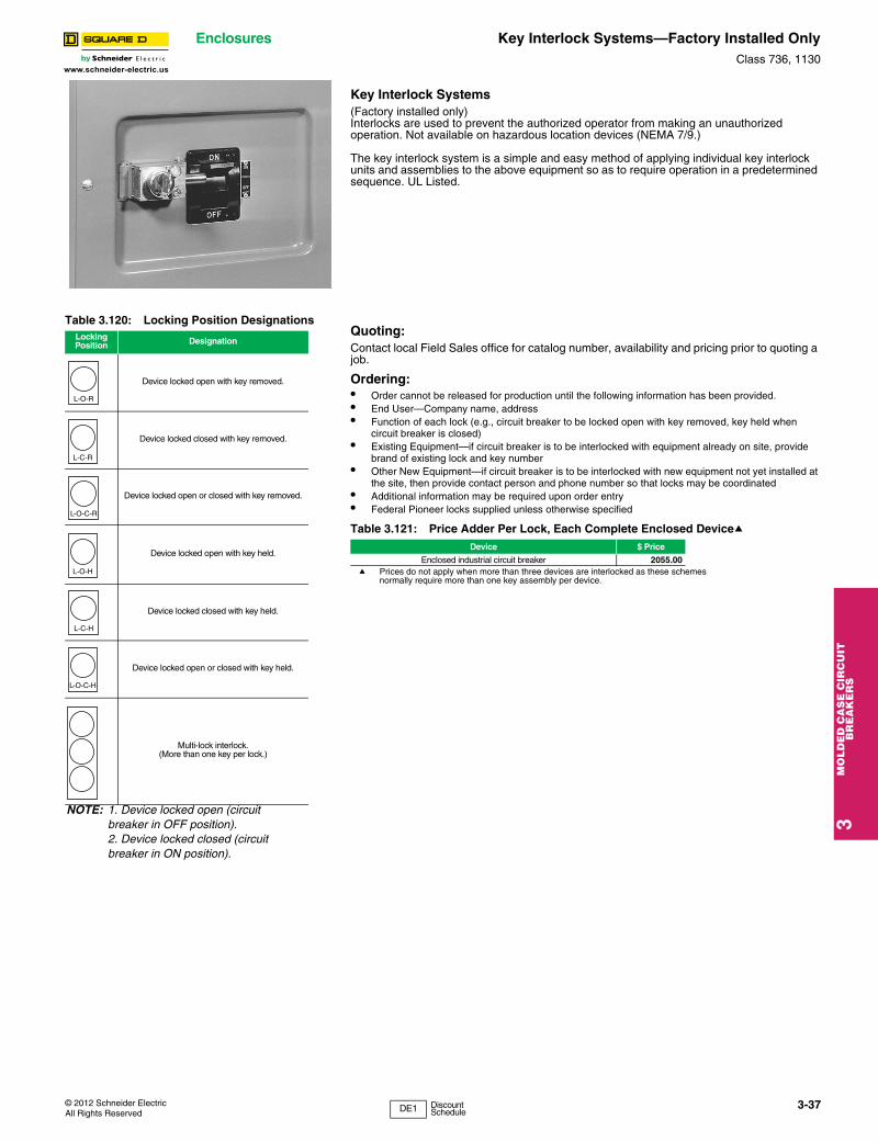
© 2012 Schneider ElectricAll Rights Reserved
Enclosures Key Interlock Systems—Factory Installed OnlyClass 736, 1130
3M
OL
DE
D C
AS
E C
IRC
UIT
B
RE
AK
ER
S
www.schneider-electric.us
Key Interlock Systems(Factory installed only)Interlocks are used to prevent the authorized operator from making an unauthorized operation. Not available on hazardous location devices (NEMA 7/9.)
The key interlock system is a simple and easy method of applying individual key interlock units and assemblies to the above equipment so as to require operation in a predetermined sequence. UL Listed.
Quoting:Contact local Field Sales office for catalog number, availability and pricing prior to quoting a job.
Ordering:• Order cannot be released for production until the following information has been provided.• End User—Company name, address• Function of each lock (e.g., circuit breaker to be locked open with key removed, key held when
circuit breaker is closed)• Existing Equipment—if circuit breaker is to be interlocked with equipment already on site, provide
brand of existing lock and key number• Other New Equipment—if circuit breaker is to be interlocked with new equipment not yet installed at
the site, then provide contact person and phone number so that locks may be coordinated• Additional information may be required upon order entry• Federal Pioneer locks supplied unless otherwise specified
a Prices do not apply when more than three devices are interlocked as these schemes normally require more than one key assembly per device.
Table 3.120: Locking Position DesignationsLocking Position Designation
Device locked open with key removed.
Device locked closed with key removed.
Device locked open or closed with key removed.
Device locked open with key held.
Device locked closed with key held.
Device locked open or closed with key held.
Multi-lock interlock.(More than one key per lock.)
NOTE: 1. Device locked open (circuit breaker in OFF position).2. Device locked closed (circuit breaker in ON position).
L-O-R
L-C-R
L-O-C-R
L-O-H
L-C-H
L-O-C-H
Table 3.121: Price Adder Per Lock, Each Complete Enclosed DeviceaDevice $ Price
Enclosed industrial circuit breaker 2055.00
3-37
DE1 Discount Schedule
3M
OLD
ED
CA
SE
CIR
CU
IT
BR
EA
KE
RS
Enclosures Special ApplicationsClass 610
www.schneider-electric.us
Sample Application—1To prevent two devices from being closed simultaneously.
Two devices are shown in Figure 1. In operation they are not closed at the same time. With the interlocks arranged as shown only one key is required in the interlocking system. Both devices are shown open, therefore, the key is free. To close any one device the key is inserted and turned in that particular lock, the key is held in this lock until the device is again locked open. This simple interlocking sequence lends itself to a multitude of applications. The procedure is the same for two devices, neither of which is to be opened at the same time.
Sample Application—2To prevent opening of switch A when circuit breaker B is closed.
Switch A and circuit breaker B are in closed position. Key A-1 is held in circuit breaker B interlock.1. Open circuit breaker.2. Turn key A-1 in L-O-R interlock on circuit breaker B to lock open. Key A-1 is
now free.3. Insert key A-1 in L-C-R interlock on switch A and turn to unlock.4. Open switch A. Key A-1 is now held. Reverse sequence to restore service.
Sample Application—3To prevent operation of switch A when circuit breaker B is closed. Permits reclosing of circuit breaker for servicing when switch is locked open.
Switch A and circuit breaker B are in closed position. Key A-1 is held in circuit breaker interlock.1. Open circuit breaker.2. Turn key A-1 in L-O-R interlock on circuit breaker B to lock open. Key A-1 is
now free.3. Insert key A-1 in L-O-C-R interlock on switch A and turn to unlock.4. Open switch A.5. Turn key A-1 in L-O-C-R interlock on switch A to lock open. Key A-1 is now
free.6. Return key A-1 to circuit breaker interlock and unlock for operation during
servicing period.
Reverse sequence to restore service.
Sample Application—4 (Main-Tie-Main)To prevent paralleling of lines A and B.—Two loads, fed from either source.
Circuit breaker A is closed to supply load M. Circuit breaker B is closed to supply load N. Tie-circuit breaker C is open. Keys A-1 are held in interlocks on both circuit breakers A and B. Tie-circuit breaker C cannot be closed unless either A or B is locked open.To transfer load N to circuit breaker A, proceed as follows:1. Open circuit breaker B.2. Turn key A-1 in L-O-R interlock on circuit breaker B to lock open. Key A-1 is
now free.3. Insert Key A-1 in L-O-R interlock on tie-circuit breaker C and turn to unlock.
Key A-1 is now held.4. Close tie-circuit breaker C.
Reverse sequence to restore service.Load M can be supplied through circuit breaker B in a similar manner.
. . . . . . . . Device normally open
. . . . . . . . Device normally closed
. . . . . . . . Direction of key transfer
. . . . . . . . Key interchange number
. . . . . . . . Key
Diagram Symbols
A-1 A-2 A-3
Figure 1
A-1
A 1L-O-R L-O-R
A B
A-1
Figure 2
A-1
L-C-R L-O-R
A
B
A 1
Figure 3
A-1
L-O-C-R L-O-R
A
B
A 1
Figure 4
L-O-R
C
L-O-R
A
A
NM
A 1
L-O-R
A 1
A-1
B
B
3-38 © 2012 Schneider ElectricAll Rights Reserved
Recommended