TablesDimension and tolerance symbols
Shaft and housing fitsNormal tolerances
Chamfer dimensionsRadial internal clearance
Axial internal clearanceReduction in radial internal clearanceFAG rolling bearing greases Arcanol –
chemical/physical dataGuidelines for use
4 MH 1 medias Schaeffler Technologies
Page
Tables
Dimension andtolerance symbols
................................................................................................. 5
Shaft and housing fits ................................................................................................. 9
Normal tolerances Normal tolerances for FAG radial bearings(excluding FAG tapered roller bearings)...................................... 22
Normal tolerances for FAG tapered roller bearingsin metric sizes ........................................................................... 24
Width tolerance to tolerance class Normal ............................. 24Width tolerance to tolerance class 6X .................................... 26Restricted tolerance class 5................................................... 27
Normal tolerances for FAG tapered roller bearingsto ANSI/ABMA ........................................................................... 29
Normal tolerances for axial bearings .......................................... 30
Chamfer dimensions Chamfer dimensions for radial bearings(excluding tapered roller bearings) ............................................ 33
Chamfer dimensions for tapered roller bearings ......................... 35Chamfer dimensions for tapered roller bearingsin metric sizes....................................................................... 36Chamfer dimensions for FAG tapered roller bearingsto ANSI/ABMA....................................................................... 37
Chamfer dimensions for axial bearings ...................................... 38
Radial internal clearance Radial internal clearance of FAG deep groove ball bearings......... 39
Radial internal clearance of FAG self-aligning ball bearings ........ 40
Radial internal clearance of FAG barrel roller bearings ................ 41
Radial internal clearance of FAG cylindrical roller bearings ......... 42
Radial internal clearance of FAG toroidal roller bearings ............. 46
Axial internal clearance Axial internal clearanceof double row FAG angular contact ball bearings ........................ 50
Axial internal clearance of FAG four point contact bearings ......... 51
Reductionin radial internal clearance
................................................................................................. 52
FAG rolling bearinggreases Arcanol –
Chemical/physical data
................................................................................................. 58
Guidelines for use Mounting and dismounting methods for rolling bearings ............ 60
Measurement record.................................................................. 62
Schaeffler Technologies MH 1 medias 5
Dimension and tolerance symbols
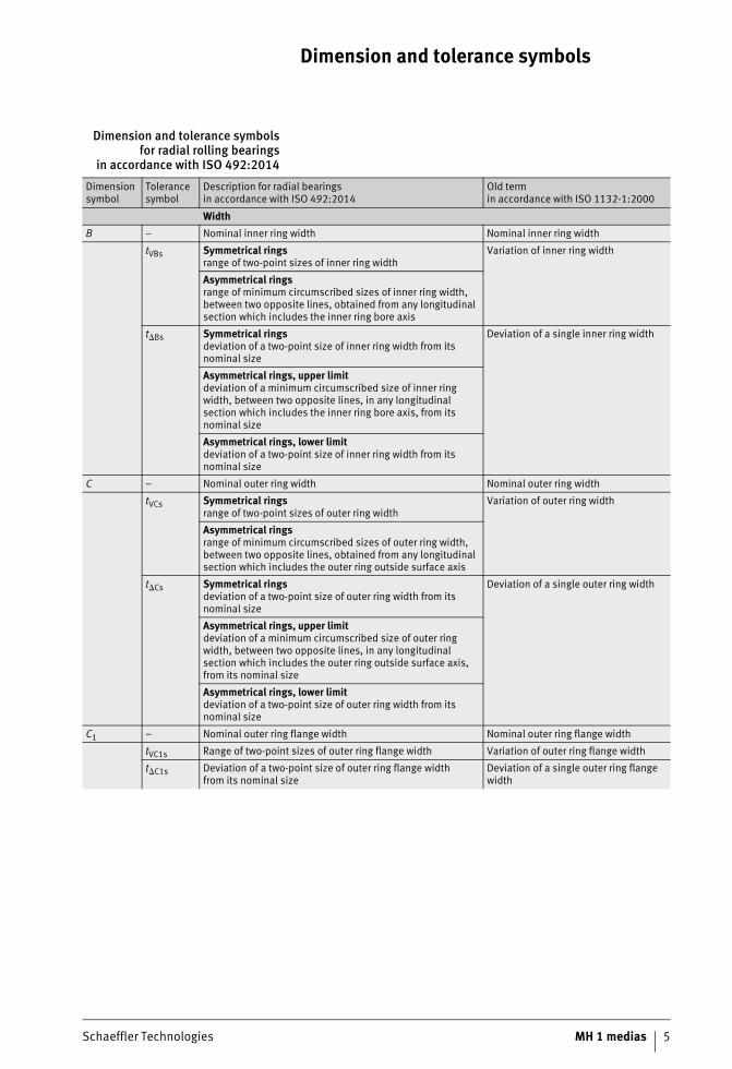
Dimension and tolerance symbolsfor radial rolling bearings
in accordance with ISO 492:2014
Dimension symbol
Tolerance symbol
Description for radial bearingsin accordance with ISO 492:2014
Old termin accordance with ISO 1132-1:2000
WidthB – Nominal inner ring width Nominal inner ring width
tVBs Symmetrical ringsrange of two-point sizes of inner ring width
Variation of inner ring width
Asymmetrical ringsrange of minimum circumscribed sizes of inner ring width, between two opposite lines, obtained from any longitudinal section which includes the inner ring bore axis
t�Bs Symmetrical ringsdeviation of a two-point size of inner ring width from its nominal size
Deviation of a single inner ring width
Asymmetrical rings, upper limitdeviation of a minimum circumscribed size of inner ring width, between two opposite lines, in any longitudinal section which includes the inner ring bore axis, from its nominal size
Asymmetrical rings, lower limitdeviation of a two-point size of inner ring width from its nominal size
C – Nominal outer ring width Nominal outer ring width
tVCs Symmetrical ringsrange of two-point sizes of outer ring width
Variation of outer ring width
Asymmetrical ringsrange of minimum circumscribed sizes of outer ring width, between two opposite lines, obtained from any longitudinal section which includes the outer ring outside surface axis
t�Cs Symmetrical ringsdeviation of a two-point size of outer ring width from its nominal size
Deviation of a single outer ring width
Asymmetrical rings, upper limitdeviation of a minimum circumscribed size of outer ring width, between two opposite lines, in any longitudinal section which includes the outer ring outside surface axis, from its nominal size
Asymmetrical rings, lower limitdeviation of a two-point size of outer ring width from its nominal size
C1 – Nominal outer ring flange width Nominal outer ring flange width
tVC1s Range of two-point sizes of outer ring flange width Variation of outer ring flange width
t�C1s Deviation of a two-point size of outer ring flange widthfrom its nominal size
Deviation of a single outer ring flange width

6 MH 1 medias Schaeffler Technologies
Dimension and tolerance symbols
Dimension and tolerance symbolsfor radial rolling bearings
in accordance with ISO 492:2014(continued)
Dimension symbol
Tolerance symbol
Description for radial bearingsin accordance with ISO 492:2014
Old termin accordance with ISO 1132-1:2000
Diameterd – Nominal bore diameter of a cylindrical bore or
at the theoretical small end of a tapered boreNominal bore diameter
tVdmp Range of mid-range sizes (out of two-point sizes)of bore diameter obtained from any cross-sectionof a cylindrical bore
Variation of mean bore diameter
t�dmp Cylindrical boredeviation of a mid-range size (out of two-point sizes)of bore diameter in any cross-section from its nominal size
Deviation of mean bore diameterin a single plane
Tapered boredeviation of a mid-range size (out of two-point sizes)of bore diameter at the theoretical small end from its nominal size
tVdsp Range of two-point sizes of bore diameter in any cross-section of a cylindrical or tapered bore
Variation of single bore diameterin a single plane
t�ds Deviation of a two-point size of bore diameterof a cylindrical bore from its nominal size
Deviation of a single bore diameter
d1 – Nominal diameter at the theoretical large endof a tapered bore
Diameter at the theoretical large endof a basically tapered bore
t�d1mp Deviation of a mid-range size (out of two-point sizes)of bore diameter at the theoretical large endof a tapered bore from its nominal size
Deviation of mean bore diameterin a single plane at the theoretical large end of a basically tapered bore
D – Nominal outside diameter Nominal outside diameter
tVDmp Range of mid-range sizes (out of two-point sizes)of outside diameter obtained from any cross-section
Variation of mean outside diameter
t�Dmp Deviation of a mid-range size (out of two-point sizes)of outside diameter in any cross-section from its nominal size
Deviation of mean outside diameterin a single plane
tVDsp Range of two-point sizes of outside diameter in any cross-section
Variation of outside diameterin a single plane
t�Ds Deviation of a two-point size of outside diameter from its nominal size
Deviation of a single outside diameter
D1 – Nominal outside diameter of outer ring flange Nominal outside diameter of outer ring flange
t�D1s Deviation of a two-point size of outside diameterof outer ring flange from its nominal size
Deviation of a single outside diameter of outer ring flange
Tapered boreSL – Taper slope is the difference between nominal diameters at
the theoretical large end and small end of a tapered bore (SL = d1 – d)
–
t�SL Deviation of taper slope of a tapered inner ring bore from its nominal size (�SL = �d1mp – �dmp)
–
� – Frustum angle of tapered inner ring bore (description based on ISO 1119)
–
Schaeffler Technologies MH 1 medias 7
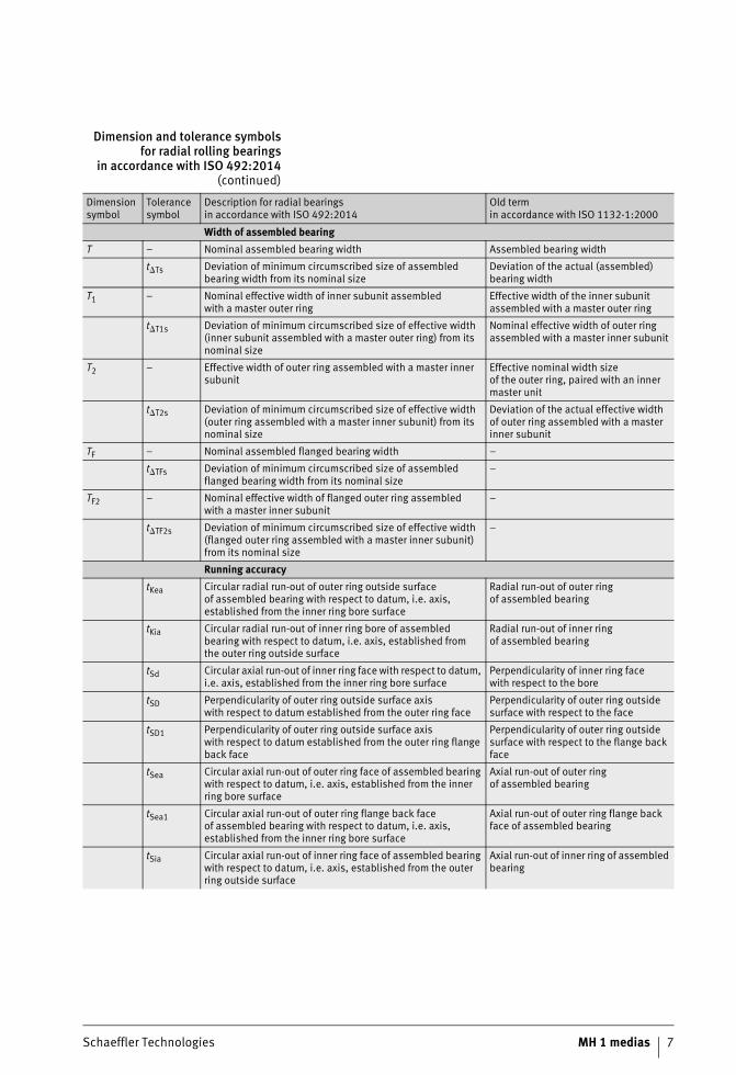
Dimension and tolerance symbolsfor radial rolling bearings
in accordance with ISO 492:2014(continued)
Dimension symbol
Tolerance symbol
Description for radial bearingsin accordance with ISO 492:2014
Old termin accordance with ISO 1132-1:2000
Width of assembled bearingT – Nominal assembled bearing width Assembled bearing width
t�Ts Deviation of minimum circumscribed size of assembled bearing width from its nominal size
Deviation of the actual (assembled) bearing width
T1 – Nominal effective width of inner subunit assembledwith a master outer ring
Effective width of the inner subunit assembled with a master outer ring
t�T1s Deviation of minimum circumscribed size of effective width (inner subunit assembled with a master outer ring) from its nominal size
Nominal effective width of outer ring assembled with a master inner subunit
T2 – Effective width of outer ring assembled with a master inner subunit
Effective nominal width sizeof the outer ring, paired with an inner master unit
t�T2s Deviation of minimum circumscribed size of effective width (outer ring assembled with a master inner subunit) from its nominal size
Deviation of the actual effective width of outer ring assembled with a master inner subunit
TF – Nominal assembled flanged bearing width –
t�TFs Deviation of minimum circumscribed size of assembled flanged bearing width from its nominal size
–
TF2 – Nominal effective width of flanged outer ring assembledwith a master inner subunit
–
t�TF2s Deviation of minimum circumscribed size of effective width (flanged outer ring assembled with a master inner subunit) from its nominal size
–
Running accuracytKea Circular radial run-out of outer ring outside surface
of assembled bearing with respect to datum, i.e. axis, established from the inner ring bore surface
Radial run-out of outer ringof assembled bearing
tKia Circular radial run-out of inner ring bore of assembled bearing with respect to datum, i.e. axis, established fromthe outer ring outside surface
Radial run-out of inner ringof assembled bearing
tSd Circular axial run-out of inner ring face with respect to datum, i.e. axis, established from the inner ring bore surface
Perpendicularity of inner ring facewith respect to the bore
tSD Perpendicularity of outer ring outside surface axiswith respect to datum established from the outer ring face
Perpendicularity of outer ring outside surface with respect to the face
tSD1 Perpendicularity of outer ring outside surface axiswith respect to datum established from the outer ring flange back face
Perpendicularity of outer ring outside surface with respect to the flange back face
tSea Circular axial run-out of outer ring face of assembled bearing with respect to datum, i.e. axis, established from the inner ring bore surface
Axial run-out of outer ringof assembled bearing
tSea1 Circular axial run-out of outer ring flange back faceof assembled bearing with respect to datum, i.e. axis, established from the inner ring bore surface
Axial run-out of outer ring flange back face of assembled bearing
tSia Circular axial run-out of inner ring face of assembled bearing with respect to datum, i.e. axis, established from the outer ring outside surface
Axial run-out of inner ring of assembled bearing
8 MH 1 medias Schaeffler Technologies
Dimension and tolerance symbols
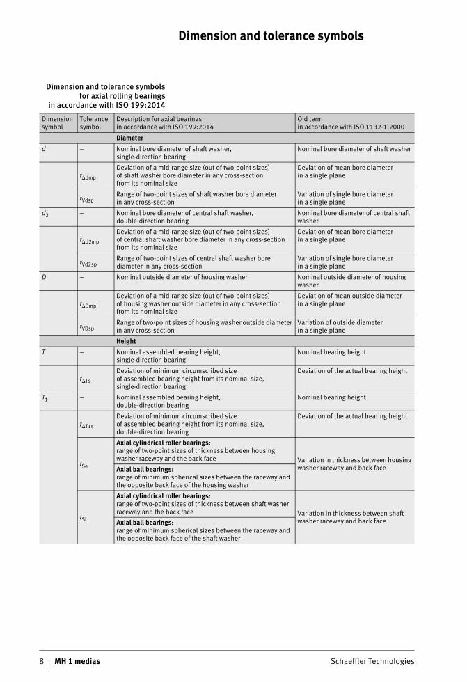
Dimension and tolerance symbolsfor axial rolling bearings
in accordance with ISO 199:2014
Dimension symbol
Tolerance symbol
Description for axial bearingsin accordance with ISO 199:2014
Old termin accordance with ISO 1132-1:2000
Diameterd – Nominal bore diameter of shaft washer,
single-direction bearingNominal bore diameter of shaft washer
t�dmp
Deviation of a mid-range size (out of two-point sizes)of shaft washer bore diameter in any cross-sectionfrom its nominal size
Deviation of mean bore diameterin a single plane
tVdspRange of two-point sizes of shaft washer bore diameterin any cross-section
Variation of single bore diameterin a single plane
d2 – Nominal bore diameter of central shaft washer, double-direction bearing
Nominal bore diameter of central shaft washer
t�d2mp
Deviation of a mid-range size (out of two-point sizes)of central shaft washer bore diameter in any cross-section from its nominal size
Deviation of mean bore diameterin a single plane
tVd2spRange of two-point sizes of central shaft washer bore diameter in any cross-section
Variation of single bore diameterin a single plane
D – Nominal outside diameter of housing washer Nominal outside diameter of housing washer
t�Dmp
Deviation of a mid-range size (out of two-point sizes)of housing washer outside diameter in any cross-section from its nominal size
Deviation of mean outside diameterin a single plane
tVDspRange of two-point sizes of housing washer outside diameter in any cross-section
Variation of outside diameterin a single plane
HeightT – Nominal assembled bearing height,
single-direction bearingNominal bearing height
t�Ts
Deviation of minimum circumscribed sizeof assembled bearing height from its nominal size, single-direction bearing
Deviation of the actual bearing height
T1 – Nominal assembled bearing height,double-direction bearing
Nominal bearing height
t�T1s
Deviation of minimum circumscribed sizeof assembled bearing height from its nominal size, double-direction bearing
Deviation of the actual bearing height
tSe
Axial cylindrical roller bearings:range of two-point sizes of thickness between housing washer raceway and the back face Variation in thickness between housing
washer raceway and back faceAxial ball bearings:range of minimum spherical sizes between the raceway and the opposite back face of the housing washer
tSi
Axial cylindrical roller bearings:range of two-point sizes of thickness between shaft washer raceway and the back face Variation in thickness between shaft
washer raceway and back faceAxial ball bearings:range of minimum spherical sizes between the raceway and the opposite back face of the shaft washer

9 MH 1 medias Schaeffler Technologies
Shaft and housing fits
Shaft and housing fits
10 MH 1 medias Schaeffler Technologies
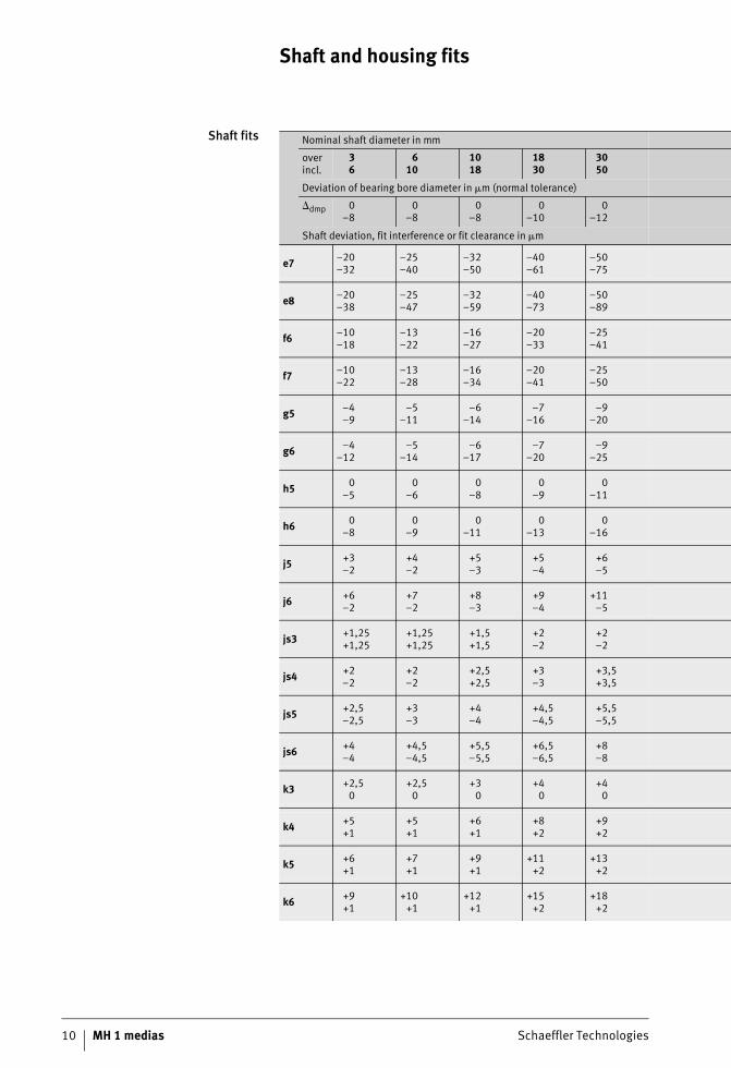
Shaft fits Nominal shaft diameter in mm
overincl.
36
610
1018
1830
3050
Deviation of bearing bore diameter in �m (normal tolerance)
�dmp 0–8
0–8
0–8
0–10
0–12
Shaft deviation, fit interference or fit clearance in �m
e7 –20–32
–25–40
–32–50
–40–61
–50–75
e8 –20–38
–25–47
–32–59
–40–73
–50–89
f6 –10–18
–13–22
–16–27
–20–33
–25–41
f7 –10–22
–13–28
–16–34
–20–41
–25–50
g5 –4–9
–5–11
–6–14
–7–16
–9–20
g6 –4–12
–5–14
–6–17
–7–20
–9–25
h5 0–5
0–6
0–8
0–9
0–11
h6 0–8
0–9
0–11
0–13
0–16
j5 +3–2
+4–2
+5–3
+5–4
+6–5
j6 +6–2
+7–2
+8–3
+9–4
+11–5
js3 +1,25+1,25
+1,25+1,25
+1,5+1,5
+2–2
+2–2
js4 +2–2
+2–2
+2,5+2,5
+3–3
+3,5+3,5
js5 +2,5–2,5
+3–3
+4–4
+4,5–4,5
+5,5–5,5
js6 +4–4
+4,5–4,5
+5,5–5,5
+6,5–6,5
+8–8
k3 +2,50
+2,50
+30
+40
+40
k4 +5+1
+5+1
+6+1
+8+2
+9+2
k5 +6+1
+7+1
+9+1
+11+2
+13+2
k6 +9+1
+10+1
+12+1
+15+2
+18+2
Schaeffler Technologies MH 1 medias 11
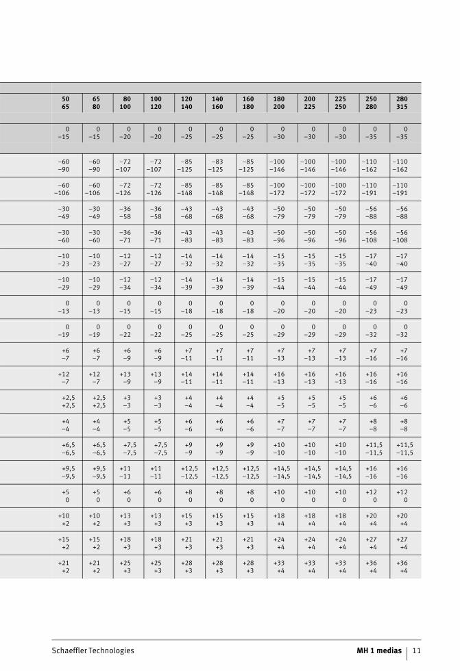
5065
6580
80100
100120
120140
140160
160180
180200
200225
225250
250280
280315
0–15
0–15
0–20
0–20
0–25
0–25
0–25
0–30
0–30
0–30
0–35
0–35
–60–90
–60–90
–72–107
–72–107
–85–125
–83–125
–85–125
–100–146
–100–146
–100–146
–110–162
–110–162
–60–106
–60–106
–72–126
–72–126
–85–148
–85–148
–85–148
–100–172
–100–172
–100–172
–110–191
–110–191
–30–49
–30–49
–36–58
–36–58
–43–68
–43–68
–43–68
–50–79
–50–79
–50–79
–56–88
–56–88
–30–60
–30–60
–36–71
–36–71
–43–83
–43–83
–43–83
–50–96
–50–96
–50–96
–56–108
–56–108
–10–23
–10–23
–12–27
–12–27
–14–32
–14–32
–14–32
–15–35
–15–35
–15–35
–17–40
–17–40
–10–29
–10–29
–12–34
–12–34
–14–39
–14–39
–14–39
–15–44
–15–44
–15–44
–17–49
–17–49
0–13
0–13
0–15
0–15
0–18
0–18
0–18
0–20
0–20
0–20
0–23
0–23
0–19
0–19
0–22
0–22
0–25
0–25
0–25
0–29
0–29
0–29
0–32
0–32
+6–7
+6–7
+6–9
+6–9
+7–11
+7–11
+7–11
+7–13
+7–13
+7–13
+7–16
+7–16
+12–7
+12–7
+13–9
+13–9
+14–11
+14–11
+14–11
+16–13
+16–13
+16–13
+16–16
+16–16
+2,5+2,5
+2,5+2,5
+3–3
+3–3
+4–4
+4–4
+4–4
+5–5
+5–5
+5–5
+6–6
+6–6
+4–4
+4–4
+5–5
+5–5
+6–6
+6–6
+6–6
+7–7
+7–7
+7–7
+8–8
+8–8
+6,5–6,5
+6,5–6,5
+7,5–7,5
+7,5–7,5
+9–9
+9–9
+9–9
+10–10
+10–10
+10–10
+11,5–11,5
+11,5–11,5
+9,5–9,5
+9,5–9,5
+11–11
+11–11
+12,5–12,5
+12,5–12,5
+12,5–12,5
+14,5–14,5
+14,5–14,5
+14,5–14,5
+16–16
+16–16
+50
+50
+60
+60
+80
+80
+80
+100
+100
+100
+120
+120
+10+2
+10+2
+13+3
+13+3
+15+3
+15+3
+15+3
+18+4
+18+4
+18+4
+20+4
+20+4
+15+2
+15+2
+18+3
+18+3
+21+3
+21+3
+21+3
+24+4
+24+4
+24+4
+27+4
+27+4
+21+2
+21+2
+25+3
+25+3
+28+3
+28+3
+28+3
+33+4
+33+4
+33+4
+36+4
+36+4
Shaft and housing fits
12 MH 1 medias Schaeffler Technologies
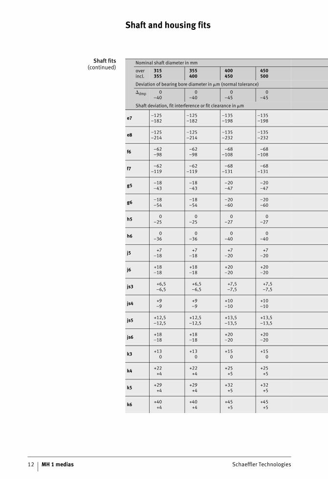
Shaft fits(continued)
Nominal shaft diameter in mm
overincl.
315355
355400
400450
450500
Deviation of bearing bore diameter in �m (normal tolerance)
�dmp 0–40
0–40
0–45
0–45
Shaft deviation, fit interference or fit clearance in �m
e7 –125–182
–125–182
–135–198
–135–198
e8 –125–214
–125–214
–135–232
–135–232
f6 –62–98
–62–98
–68–108
–68–108
f7 –62–119
–62–119
–68–131
–68–131
g5 –18–43
–18–43
–20–47
–20–47
g6 –18–54
–18–54
–20–60
–20–60
h5 0–25
0–25
0–27
0–27
h6 0–36
0–36
0–40
0–40
j5 +7–18
+7–18
+7–20
+7–20
j6 +18–18
+18–18
+20–20
+20–20
js3 +6,5–6,5
+6,5–6,5
+7,5–7,5
+7,5–7,5
js4 +9–9
+9–9
+10–10
+10–10
js5 +12,5–12,5
+12,5–12,5
+13,5–13,5
+13,5–13,5
js6 +18–18
+18–18
+20–20
+20–20
k3 +130
+130
+150
+150
k4 +22+4
+22+4
+25+5
+25+5
k5 +29+4
+29+4
+32+5
+32+5
k6 +40+4
+40+4
+45+5
+45+5
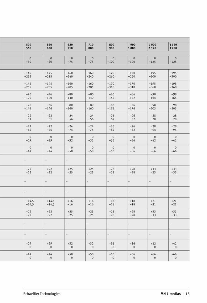
Schaeffler Technologies MH 1 medias 13
500560
560630
630710
710800
800900
9001 000
1 0001 120
1 1201 250
0–50
0–50
0–75
0–75
0–100
0–100
0–125
0–125
–145–215
–145–215
–160–240
–160–240
–170–260
–170–260
–195–300
–195–300
–145–255
–145–255
–160–285
–160–285
–170–310
–170–310
–195–360
–195–360
–76–120
–76–120
–80–130
–80–130
–86–142
–86–142
–98–164
–98–164
–76–146
–76–146
–80–160
–80–160
–86–176
–86–176
–98–203
–98–203
–22–51
–22–51
–24–56
–24–56
–26–62
–26–62
–28–70
–28–70
–22–66
–22–66
–24–74
–24–74
–26–82
–26–82
–28–94
–28–94
0–29
0–29
0–32
0–32
0–36
0–36
0–42
0–42
0–44
0–44
0–50
0–50
0–56
0–56
0–66
0–66
– – – – – – – –
+22–22
+22–22
+25–25
+25–25
+28–28
+28–28
+33–33
+33–33
– – – – – – – –
– – – – – – – –
+14,5–14,5
+14,5–14,5
+16–16
+16–16
+18–18
+18–18
+21–21
+21–21
+22–22
+22–22
+25–25
+25–25
+28–28
+28–28
+33–33
+33–33
– – – – – – – –
– – – – – – – –
+290
+290
+320
+320
+360
+360
+420
+420
+440
+440
+500
+500
+560
+560
+660
+660
Shaft and housing fits
14 MH 1 medias Schaeffler Technologies
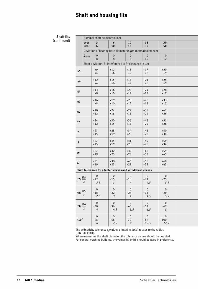
Shaft fits(continued)
The cylindricity tolerance t1(values printed in italic) relates to the radius(DIN ISO 1101).When measuring the shaft diameter, the tolerance values should be doubled.For general machine building, the values h7 or h8 should be used in preference.
Nominal shaft diameter in mm
overincl.
36
610
1018
1830
3050
Deviation of bearing bore diameter in �m (normal tolerance)
�dmp 0–8
0–8
0–8
0–10
0–12
Shaft deviation, fit interference or fit clearance in �m
m5 +9+4
+12+6
+15+7
+17+8
+20+9
m6 +12+4
+15+6
+18+7
+21+8
+25+9
n5 +13+8
+16+10
+20+12
+24+15
+28+17
n6 +16+8
+19+10
+23+12
+28+15
+33+17
p6 +20+12
+24+15
+29+18
+35+22
+42+26
p7 +24+12
+30+15
+36+18
+43+22
+51+26
r6 +23+15
+28+19
+34+23
+41+28
+50+34
r7 +27+15
+34+19
+41+23
+49+28
+59+34
s6 +27+19
+32+23
+39+28
+48+35
+59+43
s7 +31+19
+38+23
+46+28
+56+35
+68+43
Shaft tolerances for adapter sleeves and withdrawal sleeves
h7/0
–122,5
0–15
3
0–18
4
0–21
4,5
0–25
5,5
h8/0
–182,5
0–22
3
0–27
4
0–33
4,5
0–39
5,5
h9/0
–304
0–36
4,5
0–43
5,5
0–52
6,5
0–62
8
h10/0
–486
0–58
7,5
0–70
9
0–8410,5
0–100
12,5
IT52
IT52
IT62
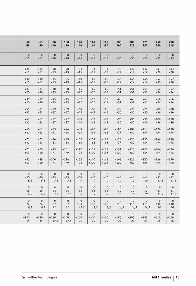
Schaeffler Technologies MH 1 medias 15
5065
6580
80100
100120
120140
140160
160180
180200
200225
225250
250280
280315
0–15
0–15
0–20
0–20
0–25
0–25
0–25
0–30
0–30
0–30
0–35
0–35
+24+11
+24+11
+28+13
+28+13
+33+15
+33+15
+33+15
+37+17
+37+17
+37+17
+43+20
+43+20
+30+11
+30+11
+35+13
+35+13
+40+15
+40+15
+40+15
+46+17
+46+17
+46+17
+52+20
+52+20
+33+20
+33+20
+38+23
+38+23
+45+27
+45+27
+45+27
+51+31
+51+31
+51+31
+57+34
+57+34
+39+20
+39+20
+45+23
+45+23
+52+27
+52+27
+52+27
+60+31
+60+31
+60+31
+66+34
+66+34
+51+32
+51+32
+59+37
+59+37
+68+43
+68+43
+68+43
+79+50
+79+50
+79+50
+88+56
+88+56
+62+32
+62+32
+72+37
+72+37
+83+43
+83+43
+83+43
+96+50
+96+50
+96+50
+108+56
+108+56
+60+41
+62+43
+73+51
+76+54
+88+63
+90+65
+93+68
+106+77
+109+80
+113+84
+126+94
+130+98
+71+41
+73+43
+86+51
+89+54
+103+63
+105+65
+108+68
+123+77
+126+80
+130+84
+146 +94
+150+98
+72+53
+78+59
+93+71
+101+79
+117+92
+125+100
+133+108
+151+122
+126+80
+130+84
+146 +94
+150+98
+83+53
+89+59
+106+71
+114+79
+132+92
+140+100
+148+108
+168+122
+126+80
+130+84
+146 +94
+150+98
0–30
6,5
0–30
6,5
0–35
7,5
0–35
7,5
0–40
9
0–40
9
0–40
9
0–4610
0–4610
0–4610
0–5211,5
0–5211,5
0–46
6,5
0–46
6,5
0–54
7,5
0–54
7,5
0–63
9
0–63
9
0–63
9
0–7210
0–7210
0–7210
0–8111,5
0–8111,5
0–74
9,5
0–74
9,5
0–8711
0–8711
0–100
12,5
0–100
12,5
0–100
12,5
0–115
14,5
0–115
14,5
0–115
14,5
0–130
16
0–130
16
0–120
15
0–120
15
0–140
17,5
0–140
17,5
0–160
20
0–160
20
0–160
20
0–185
23
0–185
23
0–185
23
0–210
26
0–210
26
Shaft and housing fits
16 MH 1 medias Schaeffler Technologies
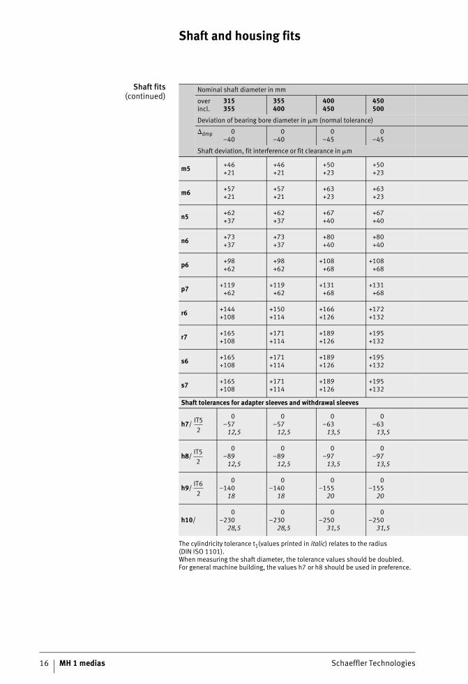
Shaft fits(continued)
The cylindricity tolerance t1(values printed in italic) relates to the radius(DIN ISO 1101).When measuring the shaft diameter, the tolerance values should be doubled.For general machine building, the values h7 or h8 should be used in preference.
Nominal shaft diameter in mm
overincl.
315355
355400
400450
450500
Deviation of bearing bore diameter in �m (normal tolerance)
�dmp 0–40
0–40
0–45
0–45
Shaft deviation, fit interference or fit clearance in �m
m5 +46+21
+46+21
+50+23
+50+23
m6 +57+21
+57+21
+63+23
+63+23
n5 +62+37
+62+37
+67+40
+67+40
n6 +73+37
+73+37
+80+40
+80+40
p6 +98+62
+98+62
+108+68
+108+68
p7 +119+62
+119+62
+131+68
+131+68
r6 +144+108
+150+114
+166+126
+172+132
r7 +165+108
+171+114
+189+126
+195+132
s6 +165+108
+171+114
+189+126
+195+132
s7 +165+108
+171+114
+189+126
+195+132
Shaft tolerances for adapter sleeves and withdrawal sleeves
h7/0
–5712,5
0–5712,5
0–6313,5
0–6313,5
h8/0
–8912,5
0–8912,5
0–9713,5
0–9713,5
h9/0
–14018
0–140
18
0–155
20
0–155
20
h10/0
–23028,5
0–230
28,5
0–250
31,5
0–250
31,5
IT52
IT52
IT62

Schaeffler Technologies MH 1 medias 17
500560
560630
630710
710800
800900
9001 000
1 0001 120
1 1201 250
0–50
0–50
0–75
0–75
0–100
0–100
0–125
0–125
+55+26
+55+26
+62+30
+62+30
+70+34
+70+34
+82+40
+82+40
+70+26
+70+26
+80+30
+80+30
+90+34
+90+34
+106+40
+106+40
+73+44
+73+44
+82+50
+82+50
+92+56
+92+56
+108+66
+108+66
+88+44
+88+44
+100+50
+100+50
+112+56
+112+56
+132+66
+132+66
+122+78
+122+78
+138+88
+138+88
+156+100
+156+100
+186+120
+186+120
+148+78
+148+78
+168+88
+168+88
+190+100
+190+100
+225+120
+225+120
+194+150
+199+155
+225+175
+235+185
+266+210
+276+220
+316+250
+326+260
+220+150
+225+155
+255+175
+265+185
+300+210
+310+220
+355+250
+365+260
+220+150
+225+155
+255+175
+265+185
+300+210
+310+220
+355+250
+365+260
+220+150
+225+155
+255+175
+265+185
+300+210
+310+220
+355+250
+365+260
0–7014,5
0–7014,5
0–8016
0–8016
0–9018
0–9018
0–105
21
0–105
21
0–110
14,5
0–110
14,5
0–125
16
0–125
16
0–140
18
0–140
18
0–165
21
0–165
21
0–175
22
0–175
22
0–200
25
0–200
25
0–230
28
0–230
28
0–260
33
0–260
33
0–280
35
0–280
35
0–320
40
0–320
40
0–360
45
0–360
45
0–420
52,5
0–420
52,5

Shaft and housing fits
18 MH 1 medias Schaeffler Technologies
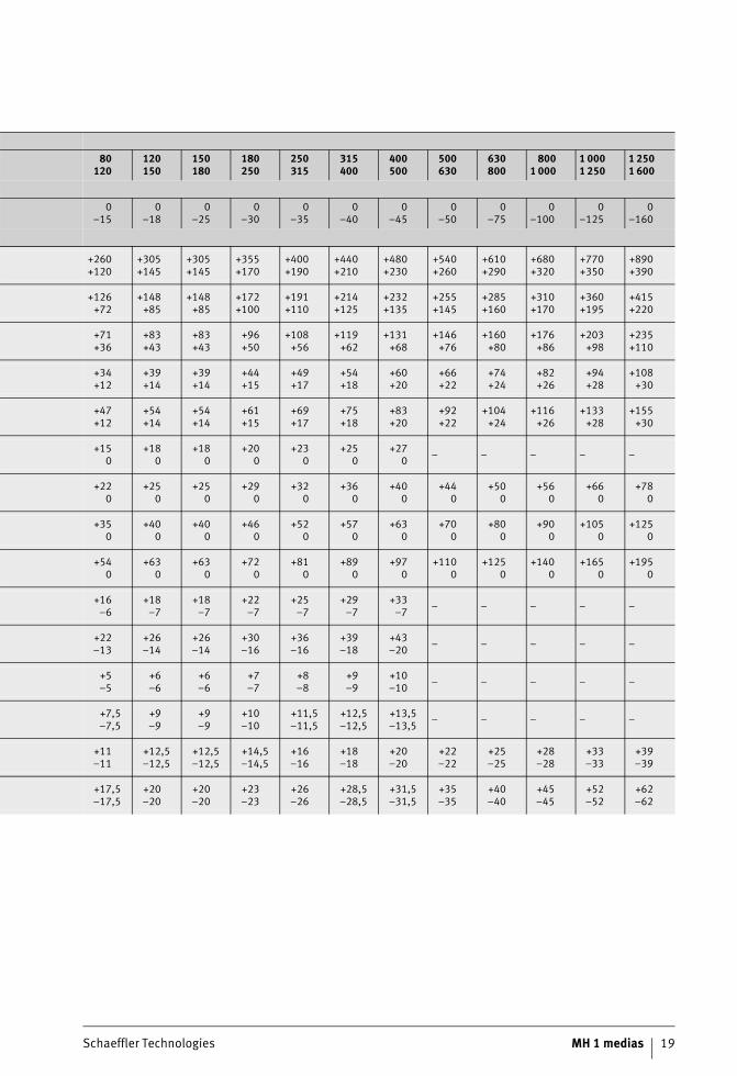
Housing fits Nominal housing bore diameter in mm
overincl.
610
1018
1830
3050
5080
Deviation of bearing outside diameter in �m (normal tolerance)
�Dmp 0–8
0–8
0–9
0–11
0–13
Housing deviation, fit interference or fit clearance in �m
D10 +98+40
+120+50
+149+65
+180+80
+220+100
E8 +47+25
+59+32
+73+40
+89+50
+106+60
F7 +28+13
+34+16
+41+20
+50+25
+60+30
G6 +14+5
+17+6
+20+7
+25+9
+29+10
G7 +20+5
+24+6
+28+7
+34+9
+40+10
H5 +60
+80
+90
+110
+130
H6 +90
+110
+130
+160
+190
H7 +150
+180
+210
+250
+300
H8 +220
+270
+330
+390
+460
J6 +5–4
+6–5
+8–5
+10–6
+13–6
J7 +8–7
+10–8
+12–9
+14–11
+18–12
JS4 +2–2
+2,5–2,5
+3–3
+3,5–3,5
+4–4
JS5 +3–3
+4–4
+4,5–4,5
+5,5–5,5
+6,5–6,5
JS6 +4,5–4,5
+5,5–5,5
+6,5–6,5
+8–8
+9,5–9,5
JS7 +7,5–7,5
+9–9
+10,5–10,5
+12,5–12,5
+15–15
Schaeffler Technologies MH 1 medias 19
80120
120150
150180
180250
250315
315400
400500
500630
630800
8001 000
1 0001 250
1 2501 600
0–15
0–18
0–25
0–30
0–35
0–40
0–45
0–50
0–75
0–100
0–125
0–160
+260+120
+305+145
+305+145
+355+170
+400+190
+440+210
+480+230
+540+260
+610+290
+680+320
+770+350
+890+390
+126+72
+148+85
+148+85
+172+100
+191+110
+214+125
+232+135
+255+145
+285+160
+310+170
+360+195
+415+220
+71+36
+83+43
+83+43
+96+50
+108+56
+119+62
+131+68
+146+76
+160+80
+176+86
+203+98
+235+110
+34+12
+39+14
+39+14
+44+15
+49+17
+54+18
+60+20
+66+22
+74+24
+82+26
+94+28
+108+30
+47+12
+54+14
+54+14
+61+15
+69+17
+75+18
+83+20
+92+22
+104+24
+116+26
+133+28
+155+30
+150
+180
+180
+200
+230
+250
+270 – – – – –
+220
+250
+250
+290
+320
+360
+400
+440
+500
+560
+660
+780
+350
+400
+400
+460
+520
+570
+630
+700
+800
+900
+1050
+1250
+540
+630
+630
+720
+810
+890
+970
+1100
+1250
+1400
+1650
+1950
+16–6
+18–7
+18–7
+22–7
+25–7
+29–7
+33–7 – – – – –
+22–13
+26–14
+26–14
+30–16
+36–16
+39–18
+43–20 – – – – –
+5–5
+6–6
+6–6
+7–7
+8–8
+9–9
+10–10 – – – – –
+7,5–7,5
+9–9
+9–9
+10–10
+11,5–11,5
+12,5–12,5
+13,5–13,5 – – – – –
+11–11
+12,5–12,5
+12,5–12,5
+14,5–14,5
+16–16
+18–18
+20–20
+22–22
+25–25
+28–28
+33–33
+39–39
+17,5–17,5
+20–20
+20–20
+23–23
+26–26
+28,5–28,5
+31,5–31,5
+35–35
+40–40
+45–45
+52–52
+62–62
Shaft and housing fits
20 MH 1 medias Schaeffler Technologies
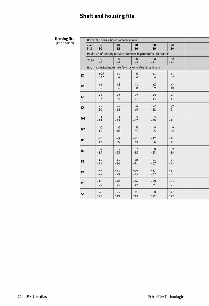
Housing fits(continued)
Nominal housing bore diameter in mm
overincl.
610
1018
1830
3050
5080
Deviation of bearing outside diameter in �m (normal tolerance)
�Dmp 0–8
0–8
0–9
0–11
0–13
Housing deviation, fit interference or fit clearance in �m
K4 +0,5–3,5
+1–4
0–6
+1–6
+1–7
K5 +1–5
+2–6
+1–8
+2–9
+3–10
K6 +2–7
+2–9
+2–11
+3–13
+4–15
K7 +5–10
+6–12
+6–15
+7–18
+9–21
M6 –3–12
–4–15
–4–17
–4–20
–5–24
M7 0–15
0–18
0–21
0–25
0–30
N6 –7–16
–9–20
–11–24
–12–28
–14–33
N7 –4–19
–5–23
–7–28
–8–33
–9–39
P6 –12–21
–15–26
–18–31
–21–37
–26–45
P7 –9–24
–11–29
–14–35
–17–42
–21–51
R6 –16–25
–20–31
–24–37
–29–45
–35–54
S7 –20–29
–25–36
–31–44
–38–54
–47–66
Schaeffler Technologies MH 1 medias 21
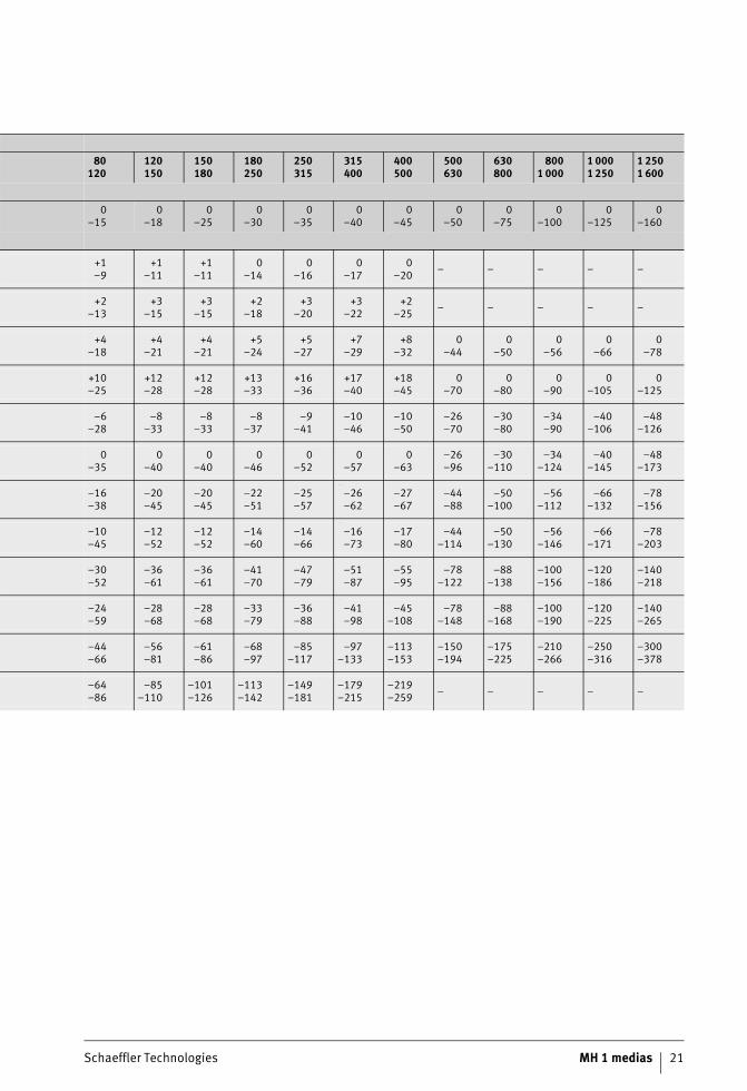
80120
120150
150180
180250
250315
315400
400500
500630
630800
8001 000
1 0001 250
1 2501 600
0–15
0–18
0–25
0–30
0–35
0–40
0–45
0–50
0–75
0–100
0–125
0–160
+1–9
+1–11
+1–11
0–14
0–16
0–17
0–20 – – – – –
+2–13
+3–15
+3–15
+2–18
+3–20
+3–22
+2–25 – – – – –
+4–18
+4–21
+4–21
+5–24
+5–27
+7–29
+8–32
0–44
0–50
0–56
0–66
0–78
+10–25
+12–28
+12–28
+13–33
+16–36
+17–40
+18–45
0–70
0–80
0–90
0–105
0–125
–6–28
–8–33
–8–33
–8–37
–9–41
–10–46
–10–50
–26–70
–30–80
–34–90
–40–106
–48–126
––0–35
0–40
0–40
0–46
0–52
0–57
0–63
–26–96
–30–110
–34–124
–40–145
–48–173
–––16–38
–20–45
–20–45
–22–51
–25–57
–26–62
–27–67
–44–88
–50–100
–56–112
–66–132
–78–156
–––10–45
–12–52
–12–52
–14–60
–14–66
–16–73
–17–80
–44–114
–50–130
–56–146
–66–171
–78–203
–––30–52
–36–61
–36–61
–41–70
–47–79
–51–87
–55–95
–78–122
–88–138
–100–156
–120–186
–140–218
–––24–59
–28–68
–28–68
–33–79
–36–88
–41–98
–45–108
–78–148
–88–168
–100–190
–120–225
–140–265
––44–66
–56–81
–61–86
–68–97
–85–117
–97–133
–113–153
–150–194
–175–225
–210–266
–250–316
–300–378
––64–86
–85–110
–101–126
–113–142
–149–181
–179–215
–219–259 – – – – –
22 MH 1 medias Schaeffler Technologies
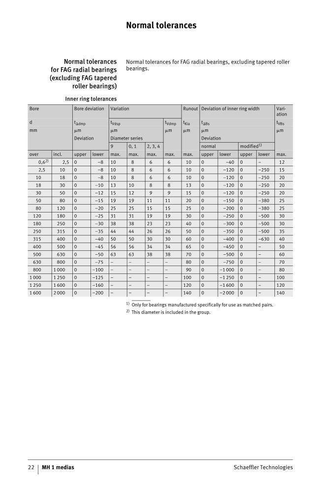
Normal tolerances
Normal tolerancesfor FAG radial bearings(excluding FAG tapered
roller bearings)
Normal tolerances for FAG radial bearings, excluding tapered roller bearings.
Inner ring tolerances
1) Only for bearings manufactured specifically for use as matched pairs.2) This diameter is included in the group.
Bore Bore deviation Variation Runout Deviation of inner ring width Vari-ation
d t�dmp tVdsp tVdmp tKia t�Bs tVBs
mm �m �m �m �m �m �m
Deviation Diameter series Deviation
9 0, 1 2, 3, 4 normal modified1)
over incl. upper lower max. max. max. max. max. upper lower upper lower max.
0,62) 2,5 0 –8 10 8 6 6 10 0 –40 0 – 12
2,5 10 0 –8 10 8 6 6 10 0 –120 0 –250 15
10 18 0 –8 10 8 6 6 10 0 –120 0 –250 20
18 30 0 –10 13 10 8 8 13 0 –120 0 –250 20
30 50 0 –12 15 12 9 9 15 0 –120 0 –250 20
50 80 0 –15 19 19 11 11 20 0 –150 0 –380 25
80 120 0 –20 25 25 15 15 25 0 –200 0 –380 25
120 180 0 –25 31 31 19 19 30 0 –250 0 –500 30
180 250 0 –30 38 38 23 23 40 0 –300 0 –500 30
250 315 0 –35 44 44 26 26 50 0 –350 0 –500 35
315 400 0 –40 50 50 30 30 60 0 –400 0 –630 40
400 500 0 –45 56 56 34 34 65 0 –450 0 – 50
500 630 0 –50 63 63 38 38 70 0 –500 0 – 60
630 800 0 –75 – – – – 80 0 –750 0 – 70
800 1 000 0 –100 – – – – 90 0 –1 000 0 – 80
1 000 1 250 0 –125 – – – – 100 0 –1 250 0 – 100
1 250 1 600 0 –160 – – – – 120 0 –1 600 0 – 120
1 600 2 000 0 –200 – – – – 140 0 –2 000 0 – 140
Schaeffler Technologies MH 1 medias 23
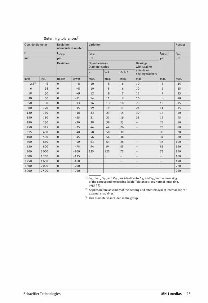
Outer ring tolerances1)
1) �Cs, �C1s, VCs and VC2s are identical to �Bs and VBs for the inner ringof the corresponding bearing (table Tolerance class Normal Inner ring, page 22).
2) Applies before assembly of the bearing and after removal of internal and/or external snap rings.
3) This diameter is included in the group.
Outside diameter Deviationof outside diameter
Variation Runout
D t�Dmp tVDsp tVDmp2) tKea
mm �m �m �m �m
Deviation Open bearingsDiameter series
Bearingswith sealing shields or sealing washers
9 0, 1 2, 3, 4
over incl. upper lower max. max. max. max. max. max.
2,53) 6 0 –8 10 8 6 10 6 15
6 18 0 –8 10 8 6 10 6 15
18 30 0 –9 12 9 7 12 7 15
30 50 0 –11 14 11 8 16 8 20
50 80 0 –13 16 13 10 20 10 25
80 120 0 –15 19 19 11 26 11 35
120 150 0 –18 23 23 14 30 14 40
150 180 0 –25 31 31 19 38 19 45
180 250 0 –30 38 38 23 – 23 50
250 315 0 –35 44 44 26 – 26 60
315 400 0 –40 50 50 30 – 30 70
400 500 0 –45 56 56 34 – 34 80
500 630 0 –50 63 63 38 – 38 100
630 800 0 –75 94 94 55 – 55 120
800 1 000 0 –100 125 125 75 – 75 140
1 000 1 250 0 –125 – – – – – 160
1 250 1 600 0 –160 – – – – – 190
1 600 2 000 0 –200 – – – – – 220
2 000 2 500 0 –250 – – – – – 250
24 MH 1 medias Schaeffler Technologies
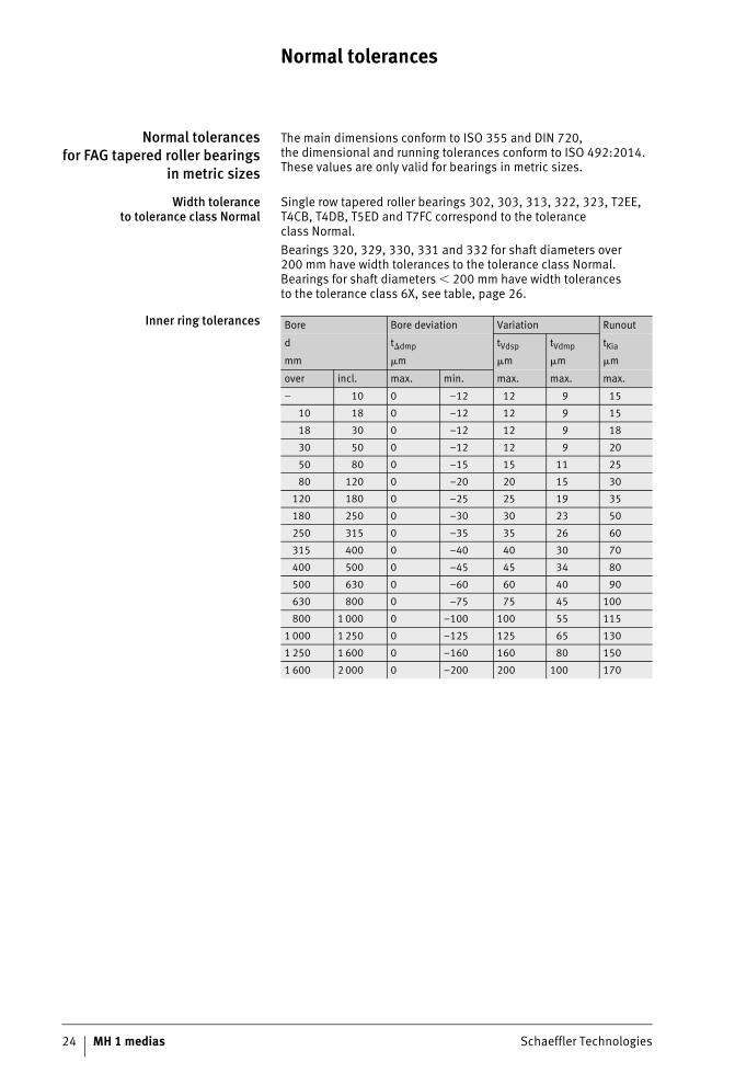
Normal tolerances
Normal tolerancesfor FAG tapered roller bearings
in metric sizes
The main dimensions conform to ISO 355 and DIN 720,the dimensional and running tolerances conform to ISO 492:2014. These values are only valid for bearings in metric sizes.
Width toleranceto tolerance class Normal
Single row tapered roller bearings 302, 303, 313, 322, 323, T2EE, T4CB, T4DB, T5ED and T7FC correspond to the tolerance class Normal.Bearings 320, 329, 330, 331 and 332 for shaft diameters over 200 mm have width tolerances to the tolerance class Normal. Bearings for shaft diameters � 200 mm have width tolerancesto the tolerance class 6X, see table, page 26.
Inner ring tolerances Bore Bore deviation Variation Runout
d t�dmp tVdsp tVdmp tKia
mm �m �m �m �m
over incl. max. min. max. max. max.
– 10 0 –12 12 9 15
10 18 0 –12 12 9 15
18 30 0 –12 12 9 18
30 50 0 –12 12 9 20
50 80 0 –15 15 11 25
80 120 0 –20 20 15 30
120 180 0 –25 25 19 35
180 250 0 –30 30 23 50
250 315 0 –35 35 26 60
315 400 0 –40 40 30 70
400 500 0 –45 45 34 80
500 630 0 –60 60 40 90
630 800 0 –75 75 45 100
800 1 000 0 –100 100 55 115
1 000 1 250 0 –125 125 65 130
1 250 1 600 0 –160 160 80 150
1 600 2 000 0 –200 200 100 170
Schaeffler Technologies MH 1 medias 25
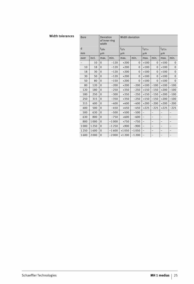
Width tolerances Bore Deviationof inner ring width
Width deviation
d t�Bs t�Ts t�T1s t�T2s
mm �m �m �m �m
over incl. max. min. max. min. max. min. max. min.
– 10 0 –120 +200 0 +100 0 +100 0
10 18 0 –120 +200 0 +100 0 +100 0
18 30 0 –120 +200 0 +100 0 +100 0
30 50 0 –120 +200 0 +100 0 +100 0
50 80 0 –150 +200 0 +100 0 +100 0
80 120 0 –200 +200 –200 +100 –100 +100 –100
120 180 0 –250 +350 –250 +150 –150 +200 –100
180 250 0 –300 +350 –250 +150 –150 +200 –100
250 315 0 –350 +350 –250 +150 –150 +200 –100
315 400 0 –400 +400 –400 +200 –200 +200 –200
400 500 0 –450 +450 –450 +225 –225 +225 –225
500 630 0 –500 +500 –500 – – – –
630 800 0 –750 +600 –600 – – – –
800 1 000 0 –1 000 +750 –750 – – – –
1 000 1 250 0 –1 250 +900 –900 – – – –
1 250 1 600 0 –1 600 +1 050 –1 050 – – – –
1 600 2 000 0 –2 000 +1 200 –1 200 – – – –
26 MH 1 medias Schaeffler Technologies
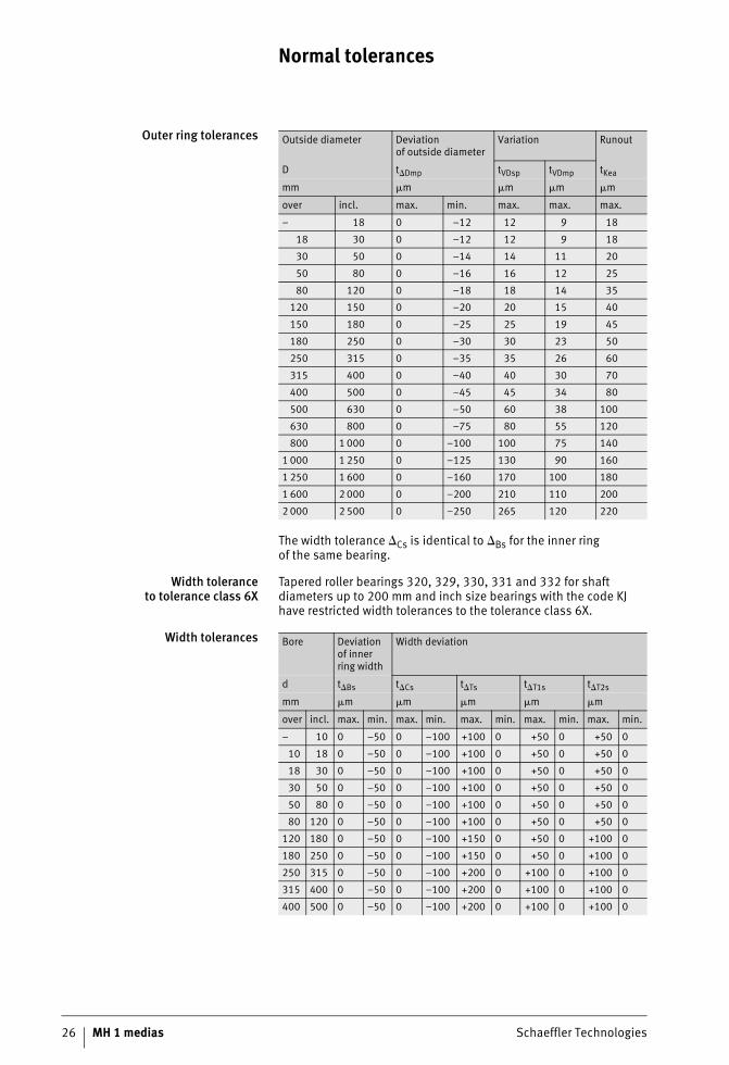
Normal tolerances
Outer ring tolerances
The width tolerance �Cs is identical to �Bs for the inner ringof the same bearing.
Width toleranceto tolerance class 6X
Tapered roller bearings 320, 329, 330, 331 and 332 for shaft diameters up to 200 mm and inch size bearings with the code KJ have restricted width tolerances to the tolerance class 6X.
Width tolerances
Outside diameter Deviationof outside diameter
Variation Runout
D t�Dmp tVDsp tVDmp tKea
mm �m �m �m �m
over incl. max. min. max. max. max.
– 18 0 –12 12 9 18
18 30 0 –12 12 9 18
30 50 0 –14 14 11 20
50 80 0 –16 16 12 25
80 120 0 –18 18 14 35
120 150 0 –20 20 15 40
150 180 0 –25 25 19 45
180 250 0 –30 30 23 50
250 315 0 –35 35 26 60
315 400 0 –40 40 30 70
400 500 0 –45 45 34 80
500 630 0 –50 60 38 100
630 800 0 –75 80 55 120
800 1 000 0 –100 100 75 140
1 000 1 250 0 –125 130 90 160
1 250 1 600 0 –160 170 100 180
1 600 2 000 0 –200 210 110 200
2 000 2 500 0 –250 265 120 220
Bore Deviation of inner ring width
Width deviation
d t�Bs t�Cs t�Ts t�T1s t�T2s
mm �m �m �m �m �m
over incl. max. min. max. min. max. min. max. min. max. min.
– 10 0 –50 0 –100 +100 0 +50 0 +50 0
10 18 0 –50 0 –100 +100 0 +50 0 +50 0
18 30 0 –50 0 –100 +100 0 +50 0 +50 0
30 50 0 –50 0 –100 +100 0 +50 0 +50 0
50 80 0 –50 0 –100 +100 0 +50 0 +50 0
80 120 0 –50 0 –100 +100 0 +50 0 +50 0
120 180 0 –50 0 –100 +150 0 +50 0 +100 0
180 250 0 –50 0 –100 +150 0 +50 0 +100 0
250 315 0 –50 0 –100 +200 0 +100 0 +100 0
315 400 0 –50 0 –100 +200 0 +100 0 +100 0
400 500 0 –50 0 –100 +200 0 +100 0 +100 0
Schaeffler Technologies MH 1 medias 27
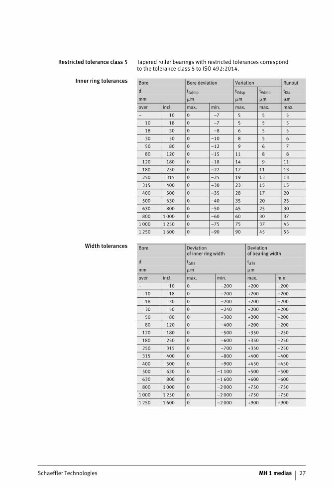
Restricted tolerance class 5 Tapered roller bearings with restricted tolerances correspondto the tolerance class 5 to ISO 492:2014.
Inner ring tolerances
Width tolerances
Bore Bore deviation Variation Runout
d t�dmp tVdsp tVdmp tKia
mm �m �m �m �m
over incl. max. min. max. max. max.
– 10 0 –7 5 5 5
10 18 0 –7 5 5 5
18 30 0 –8 6 5 5
30 50 0 –10 8 5 6
50 80 0 –12 9 6 7
80 120 0 –15 11 8 8
120 180 0 –18 14 9 11
180 250 0 –22 17 11 13
250 315 0 –25 19 13 13
315 400 0 –30 23 15 15
400 500 0 –35 28 17 20
500 630 0 –40 35 20 25
630 800 0 –50 45 25 30
800 1 000 0 –60 60 30 37
1 000 1 250 0 –75 75 37 45
1 250 1 600 0 –90 90 45 55
Bore Deviationof inner ring width
Deviationof bearing width
d t�Bs t�Ts
mm �m �m
over incl. max. min. max. min.
– 10 0 –200 +200 –200
10 18 0 –200 +200 –200
18 30 0 –200 +200 –200
30 50 0 –240 +200 –200
50 80 0 –300 +200 –200
80 120 0 –400 +200 –200
120 180 0 –500 +350 –250
180 250 0 –600 +350 –250
250 315 0 –700 +350 –250
315 400 0 –800 +400 –400
400 500 0 –900 +450 –450
500 630 0 –1 100 +500 –500
630 800 0 –1 600 +600 –600
800 1 000 0 –2 000 +750 –750
1 000 1 250 0 –2 000 +750 –750
1 250 1 600 0 –2 000 +900 –900
28 MH 1 medias Schaeffler Technologies
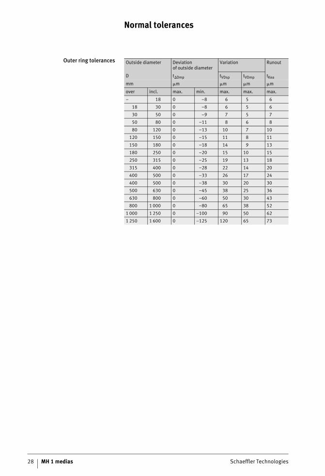
Normal tolerances
Outer ring tolerances Outside diameter Deviationof outside diameter
Variation Runout
D t�Dmp tVDsp tVDmp tKea
mm �m �m �m �m
over incl. max. min. max. max. max.
– 18 0 –8 6 5 6
18 30 0 –8 6 5 6
30 50 0 –9 7 5 7
50 80 0 –11 8 6 8
80 120 0 –13 10 7 10
120 150 0 –15 11 8 11
150 180 0 –18 14 9 13
180 250 0 –20 15 10 15
250 315 0 –25 19 13 18
315 400 0 –28 22 14 20
400 500 0 –33 26 17 24
400 500 0 –38 30 20 30
500 630 0 –45 38 25 36
630 800 0 –60 50 30 43
800 1 000 0 –80 65 38 52
1 000 1 250 0 –100 90 50 62
1 250 1 600 0 –125 120 65 73
Schaeffler Technologies MH 1 medias 29
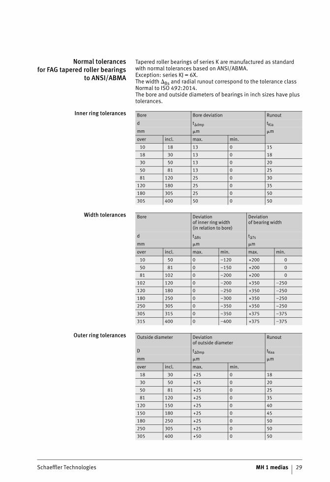
Normal tolerancesfor FAG tapered roller bearings
to ANSI/ABMA
Tapered roller bearings of series K are manufactured as standard with normal tolerances based on ANSI/ABMA.Exception: series KJ = 6X.The width �Bs and radial runout correspond to the tolerance class Normal to ISO 492:2014.The bore and outside diameters of bearings in inch sizes have plus tolerances.
Inner ring tolerances
Width tolerances
Outer ring tolerances
Bore Bore deviation Runout
d t�dmp tKia
mm �m �m
over incl. max. min.
10 18 13 0 15
18 30 13 0 18
30 50 13 0 20
50 81 13 0 25
81 120 25 0 30
120 180 25 0 35
180 305 25 0 50
305 400 50 0 50
Bore Deviationof inner ring width(in relation to bore)
Deviationof bearing width
d t�Bs t�Ts
mm �m �m
over incl. max. min. max. min.
10 50 0 –120 +200 0
50 81 0 –150 +200 0
81 102 0 –200 +200 0
102 120 0 –200 +350 –250
120 180 0 –250 +350 –250
180 250 0 –300 +350 –250
250 305 0 –350 +350 –250
305 315 0 –350 +375 –375
315 400 0 –400 +375 –375
Outside diameter Deviationof outside diameter
Runout
D t�Dmp tKea
mm �m �m
over incl. max. min.
18 30 +25 0 18
30 50 +25 0 20
50 81 +25 0 25
81 120 +25 0 35
120 150 +25 0 40
150 180 +25 0 45
180 250 +25 0 50
250 305 +25 0 50
305 400 +50 0 50
30 MH 1 medias Schaeffler Technologies
Normal tolerances
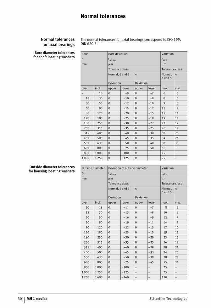
Normal tolerancesfor axial bearings
The normal tolerances for axial bearings correspond to ISO 199, DIN 620-3.
Bore diameter tolerancesfor shaft locating washers
Outside diameter tolerancesfor housing locating washers
Bore Bore deviation Variation
d t�dmp tVdp
mm �m �m
Tolerance class Tolerance class
Normal, 6 and 5 4 Normal, 6 and 5
4
Deviation Deviation
over incl. upper lower upper lower max. max.
– 18 0 –8 0 –7 6 5
18 30 0 –10 0 –8 8 6
30 50 0 –12 0 –10 9 8
50 80 0 –15 0 –12 11 9
80 120 0 –20 0 –15 15 11
120 180 0 –25 0 –18 19 14
180 250 0 –30 0 –22 23 17
250 315 0 –35 0 –25 26 19
315 400 0 –40 0 –30 30 23
400 500 0 –45 0 –35 34 26
500 630 0 –50 0 –40 38 30
630 800 0 –75 0 –50 56 –
800 1 000 0 –100 0 – 75 –
1 000 1 250 0 –125 0 – 95 –
Outside diameter Deviation of outside diameter Variation
D t�Dmp tVDp
mm �m �m
Tolerance class Tolerance class
Normal, 6 and 5 4 Normal, 6 and 5
4
Deviation Deviation
over incl. upper lower upper lower max. max.
10 18 0 –11 0 –7 8 5
18 30 0 –13 0 –8 10 6
30 50 0 –16 0 –9 12 7
50 80 0 –19 0 –11 14 8
80 120 0 –22 0 –13 17 10
120 180 0 –25 0 –15 19 11
180 250 0 –30 0 –20 23 15
250 315 0 –35 0 –25 26 19
315 400 0 –40 0 –28 30 21
400 500 0 –45 0 –33 34 25
500 630 0 –50 0 –38 38 29
630 800 0 –75 0 –45 55 34
800 1 000 0 –100 – – 75 –
1 000 1 250 0 –125 – – 75 –
1 250 1 600 0 –160 – – 120 –
Schaeffler Technologies MH 1 medias 31
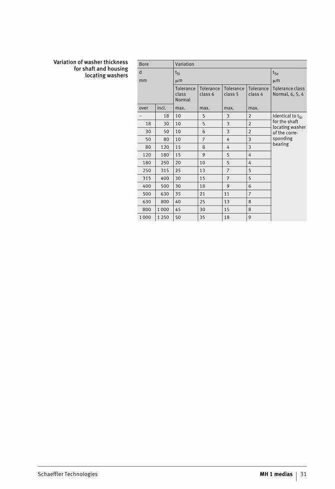
Variation of washer thicknessfor shaft and housing
locating washers
Bore Variation
d tSi tSe
mm �m �m
Tolerance class Normal
Tolerance class 6
Tolerance class 5
Tolerance class 4
Tolerance class Normal, 6, 5, 4
over incl. max. max. max. max.
– 18 10 5 3 2 Identical to tSi for the shaft locating washer of the corre-sponding bearing
18 30 10 5 3 2
30 50 10 6 3 2
50 80 10 7 4 3
80 120 15 8 4 3
120 180 15 9 5 4
180 250 20 10 5 4
250 315 25 13 7 5
315 400 30 15 7 5
400 500 30 18 9 6
500 630 35 21 11 7
630 800 40 25 13 8
800 1 000 45 30 15 8
1 000 1 250 50 35 18 9
32 MH 1 medias Schaeffler Technologies
Normal tolerances
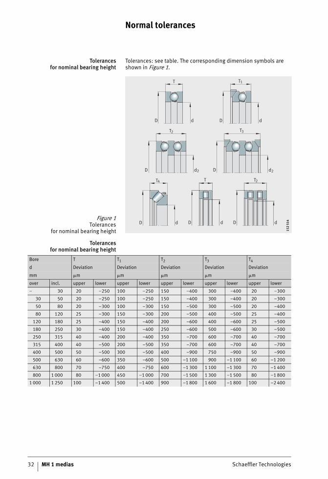
Tolerancesfor nominal bearing height
Tolerances: see table. The corresponding dimension symbols are shown in Figure 1.
Tolerancesfor nominal bearing height
Figure 1Tolerances
for nominal bearing height
D d
TT
D d
d2
T3
DD 2d
T2
dD
T1
D d
D d
T2
T
4
152
514
152
514
Bore T T1 T2 T3 T4
d Deviation Deviation Deviation Deviation Deviation
mm �m �m �m �m �m
over incl. upper lower upper lower upper lower upper lower upper lower
– 30 20 –250 100 –250 150 –400 300 –400 20 –300
30 50 20 –250 100 –250 150 –400 300 –400 20 –300
50 80 20 –300 100 –300 150 –500 300 –500 20 –400
80 120 25 –300 150 –300 200 –500 400 –500 25 –400
120 180 25 –400 150 –400 200 –600 400 –600 25 –500
180 250 30 –400 150 –400 250 –600 500 –600 30 –500
250 315 40 –400 200 –400 350 –700 600 –700 40 –700
315 400 40 –500 200 –500 350 –700 600 –700 40 –700
400 500 50 –500 300 –500 400 –900 750 –900 50 –900
500 630 60 –600 350 –600 500 –1 100 900 –1 100 60 –1 200
630 800 70 –750 400 –750 600 –1 300 1 100 –1 300 70 –1 400
800 1 000 80 –1 000 450 –1 000 700 –1 500 1 300 –1 500 80 –1 800
1 000 1 250 100 –1 400 500 –1 400 900 –1 800 1 600 –1 800 100 –2 400
Schaeffler Technologies MH 1 medias 33
Chamfer dimensions
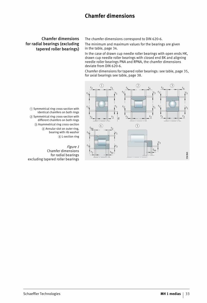
Chamfer dimensionsfor radial bearings (excluding
tapered roller bearings)
The chamfer dimensions correspond to DIN 620-6.The minimum and maximum values for the bearings are givenin the table, page 34.In the case of drawn cup needle roller bearings with open ends HK, drawn cup needle roller bearings with closed end BK and aligning needle roller bearings PNA and RPNA, the chamfer dimensions deviate from DIN 620-6.Chamfer dimensions for tapered roller bearings: see table, page 35, for axial bearings see table, page 38.
� Symmetrical ring cross-section withidentical chamfers on both rings
� Symmetrical ring cross-section withdifferent chamfers on both rings
� Asymmetrical ring cross-section� Annular slot on outer ring,
bearing with rib washer� L-section ring
Figure 1Chamfer dimensions
for radial bearingsexcluding tapered roller bearings
1 2 3
4 5
r2
r1 r1
r5 r1
r1 r3
r1r1 r1
r2
r1
r3 r3r1 r3
r1 r1
r2
r6a r2
r4 r4 r2 r4
r2r2 dr2
r2 r4a
r2 r2
r3
r4a
156
845
156
845
34 MH 1 medias Schaeffler Technologies
Chamfer dimensions
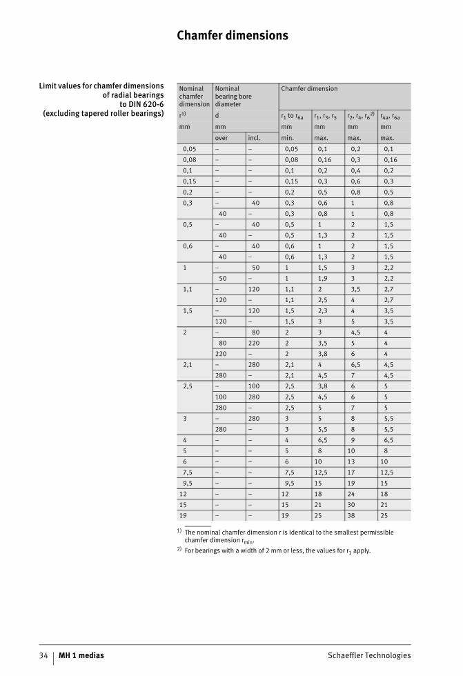
Limit values for chamfer dimensionsof radial bearings
to DIN 620-6(excluding tapered roller bearings)
1) The nominal chamfer dimension r is identical to the smallest permissible chamfer dimension rmin.
2) For bearings with a width of 2 mm or less, the values for r1 apply.
Nominal chamfer dimension
Nominalbearing bore diameter
Chamfer dimension
r1) d r1 to r6a r1, r3, r5 r2, r4, r62) r4a, r6a
mm mm mm mm mm mm
over incl. min. max. max. max.
0,05 – – 0,05 0,1 0,2 0,1
0,08 – – 0,08 0,16 0,3 0,16
0,1 – – 0,1 0,2 0,4 0,2
0,15 – – 0,15 0,3 0,6 0,3
0,2 – – 0,2 0,5 0,8 0,5
0,3 – 40 0,3 0,6 1 0,8
40 – 0,3 0,8 1 0,8
0,5 – 40 0,5 1 2 1,5
40 – 0,5 1,3 2 1,5
0,6 – 40 0,6 1 2 1,5
40 – 0,6 1,3 2 1,5
1 – 50 1 1,5 3 2,2
50 – 1 1,9 3 2,2
1,1 – 120 1,1 2 3,5 2,7
120 – 1,1 2,5 4 2,7
1,5 – 120 1,5 2,3 4 3,5
120 – 1,5 3 5 3,5
2 – 80 2 3 4,5 4
80 220 2 3,5 5 4
220 – 2 3,8 6 4
2,1 – 280 2,1 4 6,5 4,5
280 – 2,1 4,5 7 4,5
2,5 – 100 2,5 3,8 6 5
100 280 2,5 4,5 6 5
280 – 2,5 5 7 5
3 – 280 3 5 8 5,5
280 – 3 5,5 8 5,5
4 – – 4 6,5 9 6,5
5 – – 5 8 10 8
6 – – 6 10 13 10
7,5 – – 7,5 12,5 17 12,5
9,5 – – 9,5 15 19 15
12 – – 12 18 24 18
15 – – 15 21 30 21
19 – – 19 25 38 25
Schaeffler Technologies MH 1 medias 35
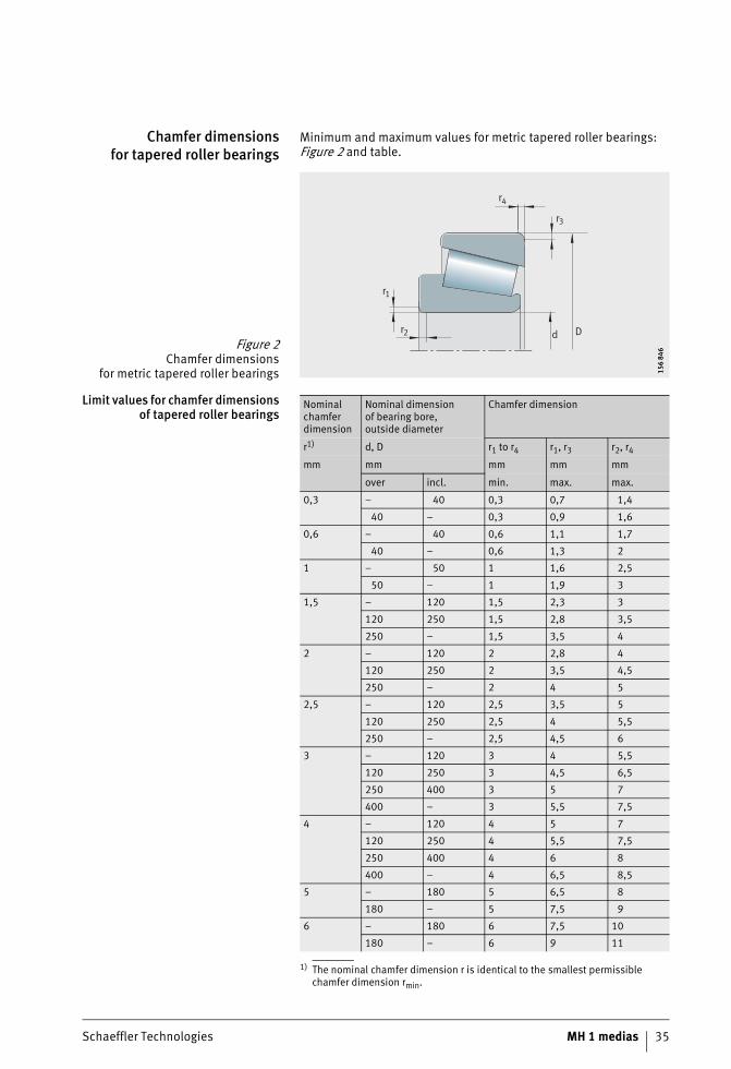
Chamfer dimensionsfor tapered roller bearings
Minimum and maximum values for metric tapered roller bearings: Figure 2 and table.
Limit values for chamfer dimensionsof tapered roller bearings
1) The nominal chamfer dimension r is identical to the smallest permissible chamfer dimension rmin.
Figure 2Chamfer dimensions
for metric tapered roller bearings
d D
r4
r3
r1
r2
156
846
156
846
Nominal chamfer dimension
Nominal dimensionof bearing bore,outside diameter
Chamfer dimension
r1) d, D r1 to r4 r1, r3 r2, r4
mm mm mm mm mm
over incl. min. max. max.
0,3 – 40 0,3 0,7 1,4
40 – 0,3 0,9 1,6
0,6 – 40 0,6 1,1 1,7
40 – 0,6 1,3 2
1 – 50 1 1,6 2,5
50 – 1 1,9 3
1,5 – 120 1,5 2,3 3
120 250 1,5 2,8 3,5
250 – 1,5 3,5 4
2 – 120 2 2,8 4
120 250 2 3,5 4,5
250 – 2 4 5
2,5 – 120 2,5 3,5 5
120 250 2,5 4 5,5
250 – 2,5 4,5 6
3 – 120 3 4 5,5
120 250 3 4,5 6,5
250 400 3 5 7
400 – 3 5,5 7,5
4 – 120 4 5 7
120 250 4 5,5 7,5
250 400 4 6 8
400 – 4 6,5 8,5
5 – 180 5 6,5 8
180 – 5 7,5 9
6 – 180 6 7,5 10
180 – 6 9 11
36 MH 1 medias Schaeffler Technologies
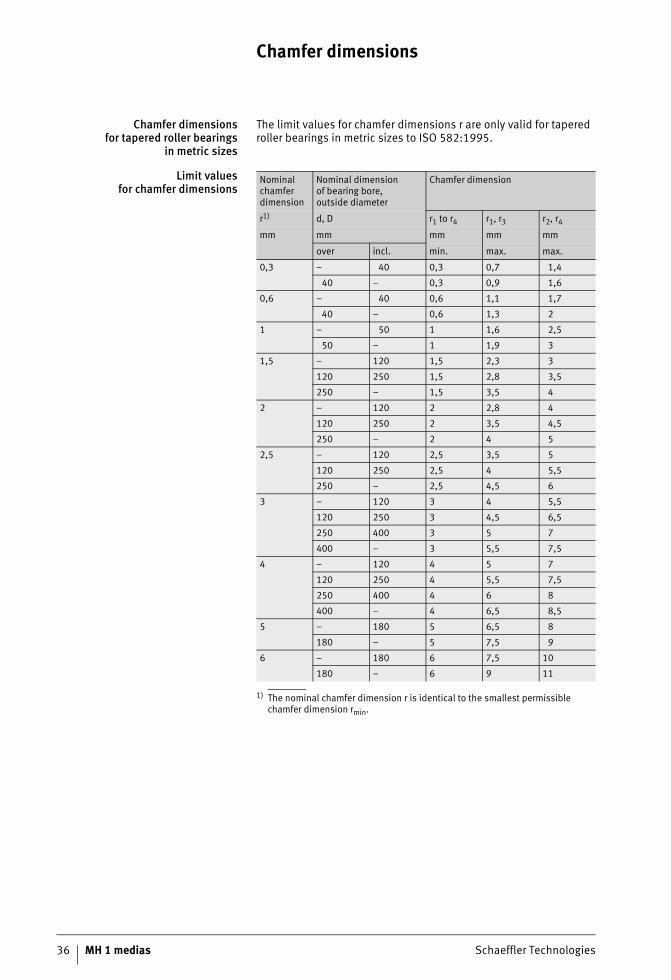
Chamfer dimensions
Chamfer dimensionsfor tapered roller bearings
in metric sizes
The limit values for chamfer dimensions r are only valid for tapered roller bearings in metric sizes to ISO 582:1995.
Limit valuesfor chamfer dimensions
1) The nominal chamfer dimension r is identical to the smallest permissible chamfer dimension rmin.
Nominal chamfer dimension
Nominal dimensionof bearing bore,outside diameter
Chamfer dimension
r1) d, D r1 to r4 r1, r3 r2, r4
mm mm mm mm mm
over incl. min. max. max.
0,3 – 40 0,3 0,7 1,4
40 – 0,3 0,9 1,6
0,6 – 40 0,6 1,1 1,7
40 – 0,6 1,3 2
1 – 50 1 1,6 2,5
50 – 1 1,9 3
1,5 – 120 1,5 2,3 3
120 250 1,5 2,8 3,5
250 – 1,5 3,5 4
2 – 120 2 2,8 4
120 250 2 3,5 4,5
250 – 2 4 5
2,5 – 120 2,5 3,5 5
120 250 2,5 4 5,5
250 – 2,5 4,5 6
3 – 120 3 4 5,5
120 250 3 4,5 6,5
250 400 3 5 7
400 – 3 5,5 7,5
4 – 120 4 5 7
120 250 4 5,5 7,5
250 400 4 6 8
400 – 4 6,5 8,5
5 – 180 5 6,5 8
180 – 5 7,5 9
6 – 180 6 7,5 10
180 – 6 9 11
Schaeffler Technologies MH 1 medias 37
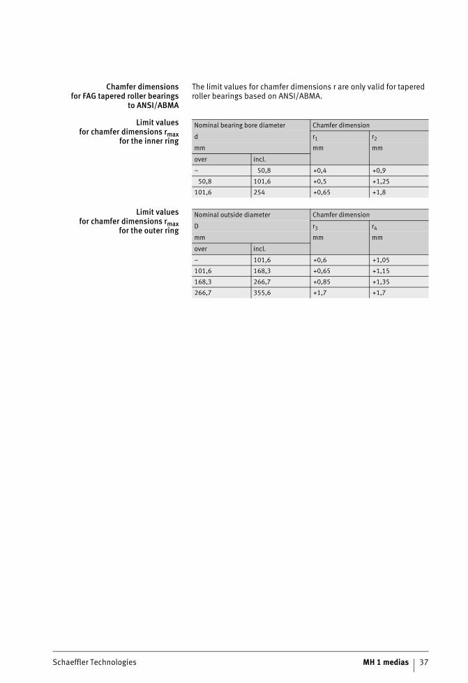
Chamfer dimensionsfor FAG tapered roller bearings
to ANSI/ABMA
The limit values for chamfer dimensions r are only valid for tapered roller bearings based on ANSI/ABMA.
Limit values for chamfer dimensions rmax
for the inner ring
Limit values for chamfer dimensions rmax
for the outer ring
Nominal bearing bore diameter Chamfer dimension
d r1 r2
mm mm mm
over incl.
– 50,8 +0,4 +0,9
50,8 101,6 +0,5 +1,25
101,6 254 +0,65 +1,8
Nominal outside diameter Chamfer dimension
D r3 r4
mm mm mm
over incl.
– 101,6 +0,6 +1,05
101,6 168,3 +0,65 +1,15
168,3 266,7 +0,85 +1,35
266,7 355,6 +1,7 +1,7
38 MH 1 medias Schaeffler Technologies
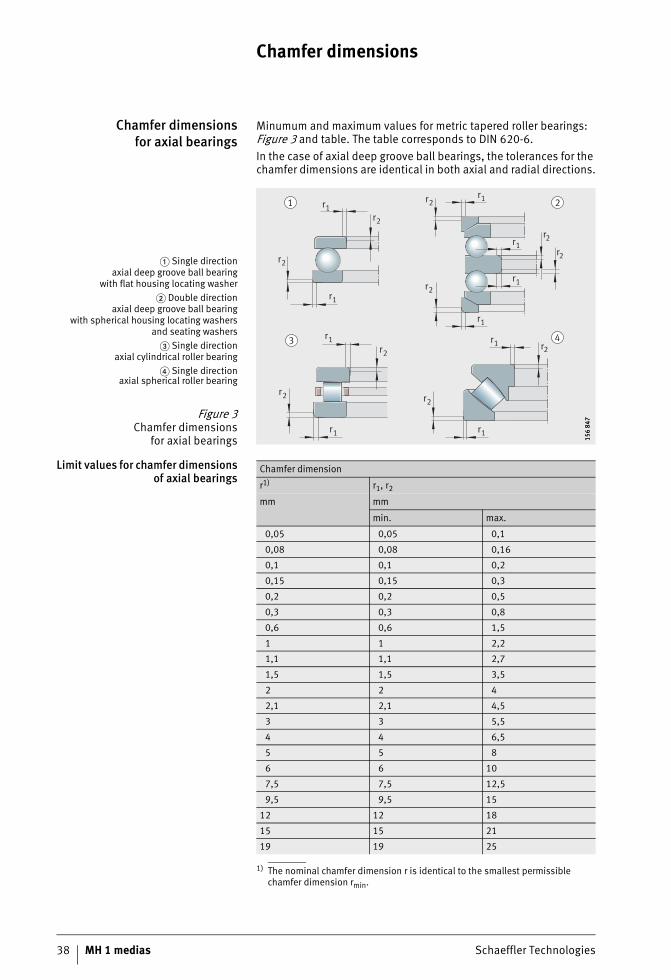
Chamfer dimensions
Chamfer dimensionsfor axial bearings
Minumum and maximum values for metric tapered roller bearings: Figure 3 and table. The table corresponds to DIN 620-6. In the case of axial deep groove ball bearings, the tolerances for the chamfer dimensions are identical in both axial and radial directions.
Limit values for chamfer dimensionsof axial bearings
1) The nominal chamfer dimension r is identical to the smallest permissible chamfer dimension rmin.
� Single directionaxial deep groove ball bearing
with flat housing locating washer� Double direction
axial deep groove ball bearingwith spherical housing locating washers
and seating washers� Single direction
axial cylindrical roller bearing� Single direction
axial spherical roller bearing
Figure 3Chamfer dimensions
for axial bearings
r1
r1
r1r1
r1
r1
r1
r1
r1
r1
r2
r2
r2r2
r2
r2
r2
r2
r2
r2 21
3 4
156
847
156
847
Chamfer dimension
r1) r1, r2
mm mm
min. max.
0,05 0,05 0,1
0,08 0,08 0,16
0,1 0,1 0,2
0,15 0,15 0,3
0,2 0,2 0,5
0,3 0,3 0,8
0,6 0,6 1,5
1 1 2,2
1,1 1,1 2,7
1,5 1,5 3,5
2 2 4
2,1 2,1 4,5
3 3 5,5
4 4 6,5
5 5 8
6 6 10
7,5 7,5 12,5
9,5 9,5 15
12 12 18
15 15 21
19 19 25
Schaeffler Technologies MH 1 medias 39
Radial internal clearance
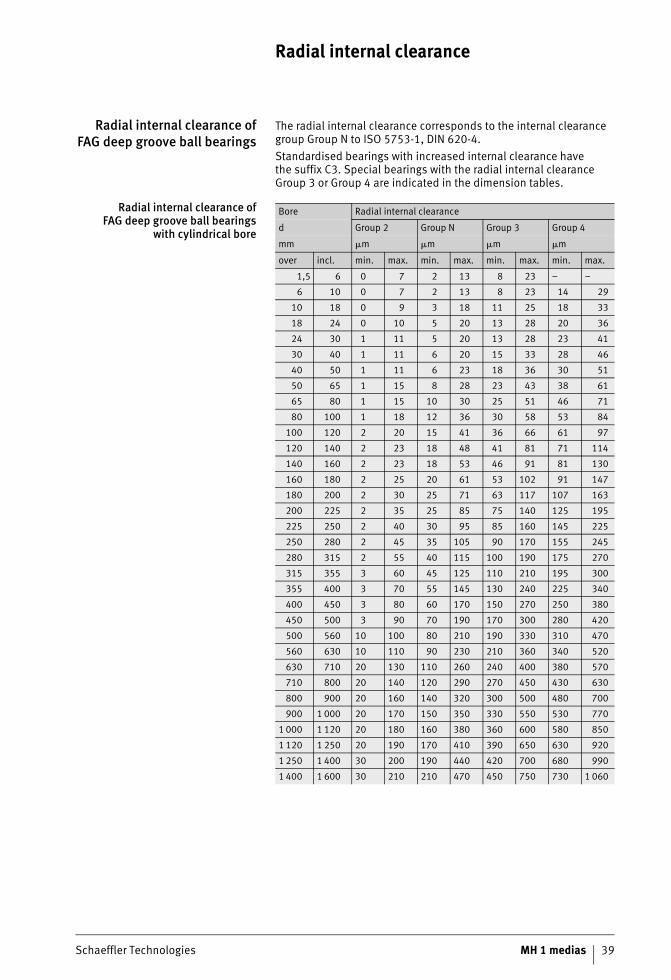
Radial internal clearance ofFAG deep groove ball bearings
The radial internal clearance corresponds to the internal clearance group Group N to ISO 5753-1, DIN 620-4.Standardised bearings with increased internal clearance havethe suffix C3. Special bearings with the radial internal clearance Group 3 or Group 4 are indicated in the dimension tables.
Radial internal clearance ofFAG deep groove ball bearings
with cylindrical bore
Bore Radial internal clearance
d Group 2 Group N Group 3 Group 4
mm �m �m �m �m
over incl. min. max. min. max. min. max. min. max.
1,5 6 0 7 2 13 8 23 – –
6 10 0 7 2 13 8 23 14 29
10 18 0 9 3 18 11 25 18 33
18 24 0 10 5 20 13 28 20 36
24 30 1 11 5 20 13 28 23 41
30 40 1 11 6 20 15 33 28 46
40 50 1 11 6 23 18 36 30 51
50 65 1 15 8 28 23 43 38 61
65 80 1 15 10 30 25 51 46 71
80 100 1 18 12 36 30 58 53 84
100 120 2 20 15 41 36 66 61 97
120 140 2 23 18 48 41 81 71 114
140 160 2 23 18 53 46 91 81 130
160 180 2 25 20 61 53 102 91 147
180 200 2 30 25 71 63 117 107 163
200 225 2 35 25 85 75 140 125 195
225 250 2 40 30 95 85 160 145 225
250 280 2 45 35 105 90 170 155 245
280 315 2 55 40 115 100 190 175 270
315 355 3 60 45 125 110 210 195 300
355 400 3 70 55 145 130 240 225 340
400 450 3 80 60 170 150 270 250 380
450 500 3 90 70 190 170 300 280 420
500 560 10 100 80 210 190 330 310 470
560 630 10 110 90 230 210 360 340 520
630 710 20 130 110 260 240 400 380 570
710 800 20 140 120 290 270 450 430 630
800 900 20 160 140 320 300 500 480 700
900 1 000 20 170 150 350 330 550 530 770
1 000 1 120 20 180 160 380 360 600 580 850
1 120 1 250 20 190 170 410 390 650 630 920
1 250 1 400 30 200 190 440 420 700 680 990
1 400 1 600 30 210 210 470 450 750 730 1 060
40 MH 1 medias Schaeffler Technologies
Radial internal clearance
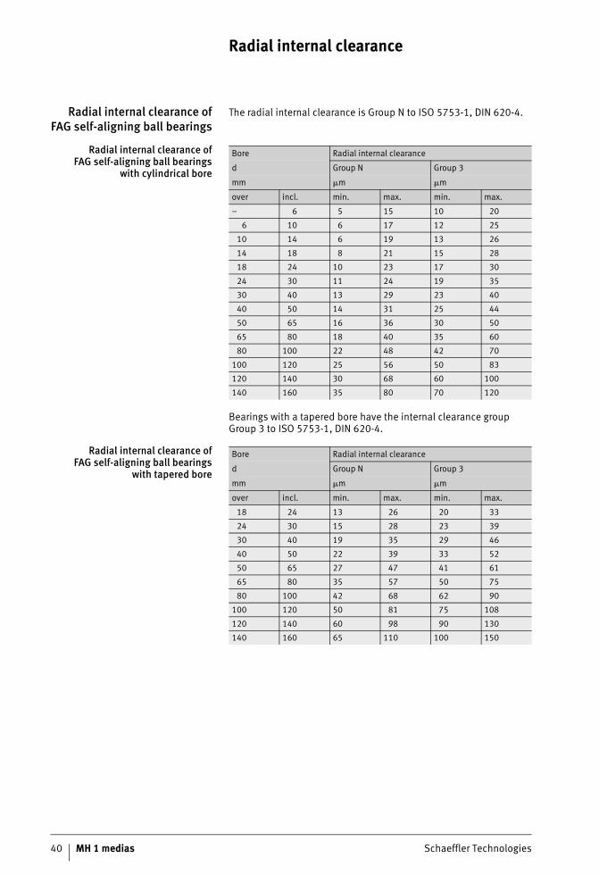
Radial internal clearance ofFAG self-aligning ball bearings
The radial internal clearance is Group N to ISO 5753-1, DIN 620-4.
Radial internal clearance ofFAG self-aligning ball bearings
with cylindrical bore
Bearings with a tapered bore have the internal clearance group Group 3 to ISO 5753-1, DIN 620-4.
Radial internal clearance ofFAG self-aligning ball bearings
with tapered bore
Bore Radial internal clearance
d Group N Group 3
mm �m �m
over incl. min. max. min. max.
– 6 5 15 10 20
6 10 6 17 12 25
10 14 6 19 13 26
14 18 8 21 15 28
18 24 10 23 17 30
24 30 11 24 19 35
30 40 13 29 23 40
40 50 14 31 25 44
50 65 16 36 30 50
65 80 18 40 35 60
80 100 22 48 42 70
100 120 25 56 50 83
120 140 30 68 60 100
140 160 35 80 70 120
Bore Radial internal clearance
d Group N Group 3
mm �m �m
over incl. min. max. min. max.
18 24 13 26 20 33
24 30 15 28 23 39
30 40 19 35 29 46
40 50 22 39 33 52
50 65 27 47 41 61
65 80 35 57 50 75
80 100 42 68 62 90
100 120 50 81 75 108
120 140 60 98 90 130
140 160 65 110 100 150
Schaeffler Technologies MH 1 medias 41
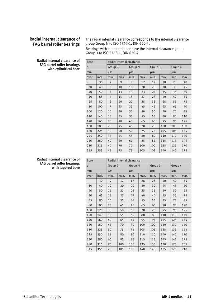
Radial internal clearance ofFAG barrel roller bearings
The radial internal clearance corresponds to the internal clearance group Group N to ISO 5753-1, DIN 620-4.Bearings with a tapered bore have the internal clearance group Group 3 to ISO 5753-1, DIN 620-4.
Radial internal clearance ofFAG barrel roller bearings
with cylindrical bore
Radial internal clearance ofFAG barrel roller bearings
with tapered bore
Bore Radial internal clearance
d Group 2 Group N Group 3 Group 4
mm �m �m �m �m
over incl. min. max. min. max. min. max. min. max.
– 30 2 9 9 17 17 28 28 40
30 40 3 10 10 20 20 30 30 45
40 50 3 13 13 23 23 35 35 50
50 65 4 15 15 27 27 40 40 55
65 80 5 20 20 35 35 55 55 75
80 100 7 25 25 45 45 65 65 90
100 120 10 30 30 50 50 70 70 95
120 140 15 35 35 55 55 80 80 110
140 160 20 40 40 65 65 95 95 125
160 180 25 45 45 70 70 100 100 130
180 225 30 50 50 75 75 105 105 135
225 250 35 55 55 80 80 110 110 140
250 280 40 60 60 85 85 115 115 145
280 315 40 70 70 100 100 135 135 170
315 355 45 75 75 105 105 140 140 175
Bore Radial internal clearance
d Group 2 Group N Group 3 Group 4
mm �m �m �m �m
over incl. min. max. min. max. min. max. min. max.
– 30 9 17 17 28 28 40 40 55
30 40 10 20 20 30 30 45 45 60
40 50 13 23 23 35 35 50 50 65
50 65 15 27 27 40 40 55 55 75
65 80 20 35 35 55 55 75 75 95
80 100 25 45 45 65 65 90 90 120
100 120 30 50 50 70 70 95 95 125
120 140 35 55 55 80 80 110 110 140
140 160 40 65 65 95 95 125 125 155
160 180 45 70 70 100 100 130 130 160
180 225 50 75 75 105 105 135 135 165
225 250 55 80 80 110 110 140 140 170
250 280 60 85 85 115 115 145 145 175
280 315 70 100 100 135 135 170 170 205
315 355 75 105 105 140 140 175 175 210
Radial internal clearance
42 MH 1 medias Schaeffler Technologies
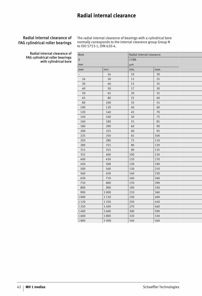
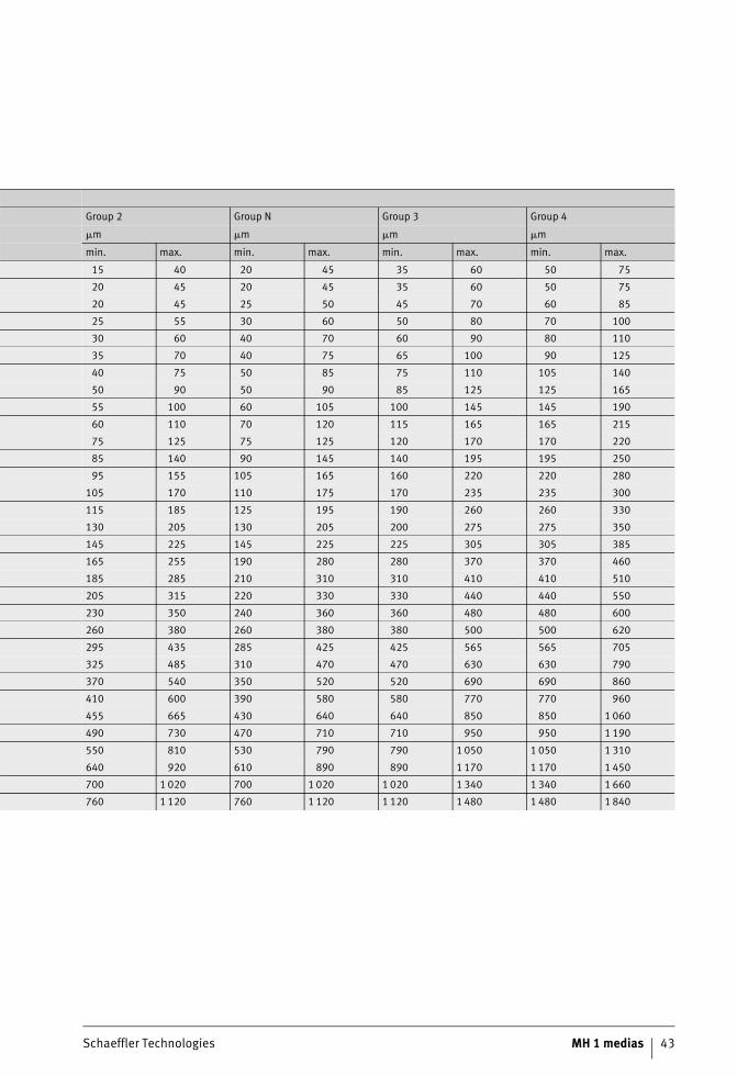
Radial internal clearance ofFAG cylindrical roller bearings
The radial internal clearance of bearings with a cylindrical borenormally corresponds to the internal clearance group Group Nto ISO 5753-1, DIN 620-4.
Radial internal clearance ofFAG cylindrical roller bearings
with cylindrical bore
Bore Radial internal clearance
d C1NA
mm �m
over incl. min. max.
– 24 10 20
24 30 15 25
30 40 15 25
40 50 17 30
50 65 20 35
65 80 25 40
80 100 35 55
100 120 40 60
120 140 45 70
140 160 50 75
160 180 55 85
180 200 60 90
200 225 60 95
225 250 65 100
250 280 75 110
280 315 80 120
315 355 90 135
355 400 100 150
400 450 110 170
450 500 120 190
500 560 130 210
560 630 140 230
630 710 160 260
710 800 170 290
800 900 190 330
900 1 000 210 360
1 000 1 120 230 400
1 120 1 250 250 440
1 250 1 400 270 460
1 400 1 600 300 500
1 600 1 800 320 530
1 800 2 000 340 560
Schaeffler Technologies MH 1 medias 43
Group 2 Group N Group 3 Group 4
�m �m �m �m
min. max. min. max. min. max. min. max.
15 40 20 45 35 60 50 75
20 45 20 45 35 60 50 75
20 45 25 50 45 70 60 85
25 55 30 60 50 80 70 100
30 60 40 70 60 90 80 110
35 70 40 75 65 100 90 125
40 75 50 85 75 110 105 140
50 90 50 90 85 125 125 165
55 100 60 105 100 145 145 190
60 110 70 120 115 165 165 215
75 125 75 125 120 170 170 220
85 140 90 145 140 195 195 250
95 155 105 165 160 220 220 280
105 170 110 175 170 235 235 300
115 185 125 195 190 260 260 330
130 205 130 205 200 275 275 350
145 225 145 225 225 305 305 385
165 255 190 280 280 370 370 460
185 285 210 310 310 410 410 510
205 315 220 330 330 440 440 550
230 350 240 360 360 480 480 600
260 380 260 380 380 500 500 620
295 435 285 425 425 565 565 705
325 485 310 470 470 630 630 790
370 540 350 520 520 690 690 860
410 600 390 580 580 770 770 960
455 665 430 640 640 850 850 1 060
490 730 470 710 710 950 950 1 190
550 810 530 790 790 1 050 1 050 1 310
640 920 610 890 890 1 170 1 170 1 450
700 1 020 700 1 020 1 020 1 340 1 340 1 660
760 1 120 760 1 120 1 120 1 480 1 480 1 840
Radial internal clearance
44 MH 1 medias Schaeffler Technologies
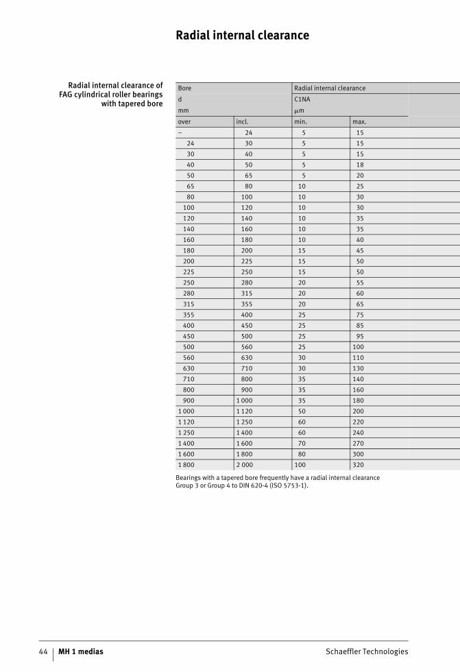
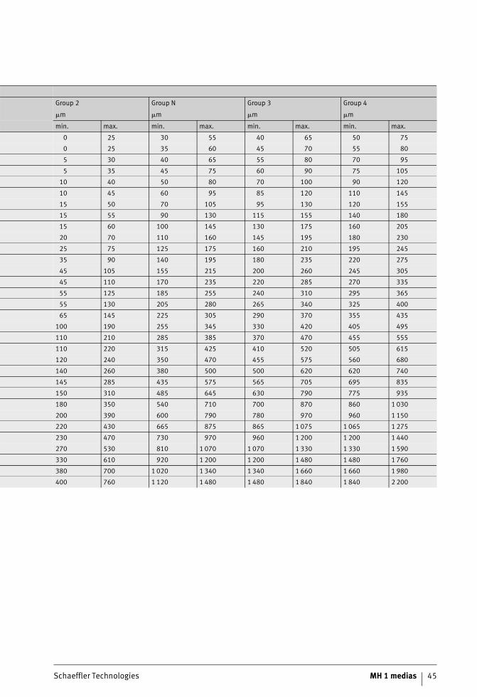
Radial internal clearance ofFAG cylindrical roller bearings
with tapered bore
Bearings with a tapered bore frequently have a radial internal clearanceGroup 3 or Group 4 to DIN 620-4 (ISO 5753-1).
Bore Radial internal clearance
d C1NA
mm �m
over incl. min. max.
– 24 5 15
24 30 5 15
30 40 5 15
40 50 5 18
50 65 5 20
65 80 10 25
80 100 10 30
100 120 10 30
120 140 10 35
140 160 10 35
160 180 10 40
180 200 15 45
200 225 15 50
225 250 15 50
250 280 20 55
280 315 20 60
315 355 20 65
355 400 25 75
400 450 25 85
450 500 25 95
500 560 25 100
560 630 30 110
630 710 30 130
710 800 35 140
800 900 35 160
900 1 000 35 180
1 000 1 120 50 200
1 120 1 250 60 220
1 250 1 400 60 240
1 400 1 600 70 270
1 600 1 800 80 300
1 800 2 000 100 320
Schaeffler Technologies MH 1 medias 45
Group 2 Group N Group 3 Group 4
�m �m �m �m
min. max. min. max. min. max. min. max.
0 25 30 55 40 65 50 75
0 25 35 60 45 70 55 80
5 30 40 65 55 80 70 95
5 35 45 75 60 90 75 105
10 40 50 80 70 100 90 120
10 45 60 95 85 120 110 145
15 50 70 105 95 130 120 155
15 55 90 130 115 155 140 180
15 60 100 145 130 175 160 205
20 70 110 160 145 195 180 230
25 75 125 175 160 210 195 245
35 90 140 195 180 235 220 275
45 105 155 215 200 260 245 305
45 110 170 235 220 285 270 335
55 125 185 255 240 310 295 365
55 130 205 280 265 340 325 400
65 145 225 305 290 370 355 435
100 190 255 345 330 420 405 495
110 210 285 385 370 470 455 555
110 220 315 425 410 520 505 615
120 240 350 470 455 575 560 680
140 260 380 500 500 620 620 740
145 285 435 575 565 705 695 835
150 310 485 645 630 790 775 935
180 350 540 710 700 870 860 1 030
200 390 600 790 780 970 960 1 150
220 430 665 875 865 1 075 1 065 1 275
230 470 730 970 960 1 200 1 200 1 440
270 530 810 1 070 1 070 1 330 1 330 1 590
330 610 920 1 200 1 200 1 480 1 480 1 760
380 700 1 020 1 340 1 340 1 660 1 660 1 980
400 760 1 120 1 480 1 480 1 840 1 840 2 200
Radial internal clearance
46 MH 1 medias Schaeffler Technologies
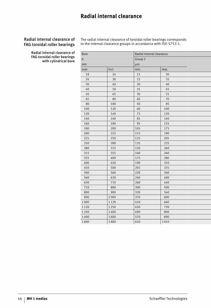
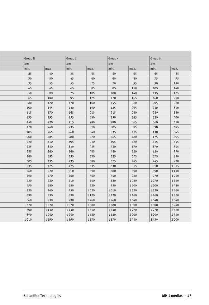
Radial internal clearance ofFAG toroidal roller bearings
The radial internal clearance of toroidal roller bearings correspondsto the internal clearance groups in accordance with ISO 5753-1.
Radial internal clearance ofFAG toroidal roller bearings
with cylindrical bore
Bore Radial internal clearance
d Group 2
mm �m
over incl. min. max.
18 24 15 30
24 30 15 35
30 40 20 40
40 50 25 45
50 65 30 55
65 80 40 70
80 100 50 85
100 120 60 100
120 140 75 120
140 160 85 140
160 180 95 155
180 200 105 175
200 225 115 190
225 250 125 205
250 280 135 225
280 315 150 240
315 355 160 260
355 400 175 280
400 450 190 310
450 500 205 335
500 560 220 360
560 630 240 400
630 710 260 440
710 800 300 500
800 900 320 540
900 1 000 370 600
1 000 1 120 410 660
1 120 1 250 450 720
1 250 1 400 490 800
1 400 1 600 570 890
1 600 1 800 650 1 010
Schaeffler Technologies MH 1 medias 47
Group N Group 3 Group 4 Group 5
�m �m �m �m
min. max. min. max. min. max. min. max.
25 40 35 55 50 65 65 85
30 50 45 60 60 80 75 95
35 55 55 75 70 95 90 120
45 65 65 85 85 110 105 140
50 80 75 105 100 140 135 175
65 100 95 125 120 165 160 210
80 120 120 160 155 210 205 260
100 145 140 190 185 245 240 310
115 170 165 215 215 280 280 350
135 195 195 250 250 325 320 400
150 220 215 280 280 365 360 450
170 240 235 310 305 395 390 495
185 265 260 340 335 435 430 545
200 285 280 370 365 480 475 605
220 310 305 410 405 520 515 655
235 330 330 435 430 570 570 715
255 360 360 485 480 620 620 790
280 395 395 530 525 675 675 850
305 435 435 580 575 745 745 930
335 475 475 635 630 815 810 1 015
360 520 510 690 680 890 890 1 110
390 570 560 760 750 980 970 1 220
430 620 610 840 830 1 080 1 070 1 340
490 680 680 920 920 1 200 1 200 1 480
530 760 750 1 020 1 010 1 330 1 320 1 660
590 830 830 1 120 1 120 1 460 1 460 1 830
660 930 930 1 260 1 260 1 640 1 640 2 040
720 1 020 1 020 1 380 1 380 1 800 1 800 2 240
800 1 130 1 130 1 510 1 540 1 970 1 970 2 460
890 1 250 1 250 1 680 1 680 2 200 2 200 2 740
1 010 1 390 1 390 1 870 1 870 2 430 2 430 3 000
Radial internal clearance
48 MH 1 medias Schaeffler Technologies
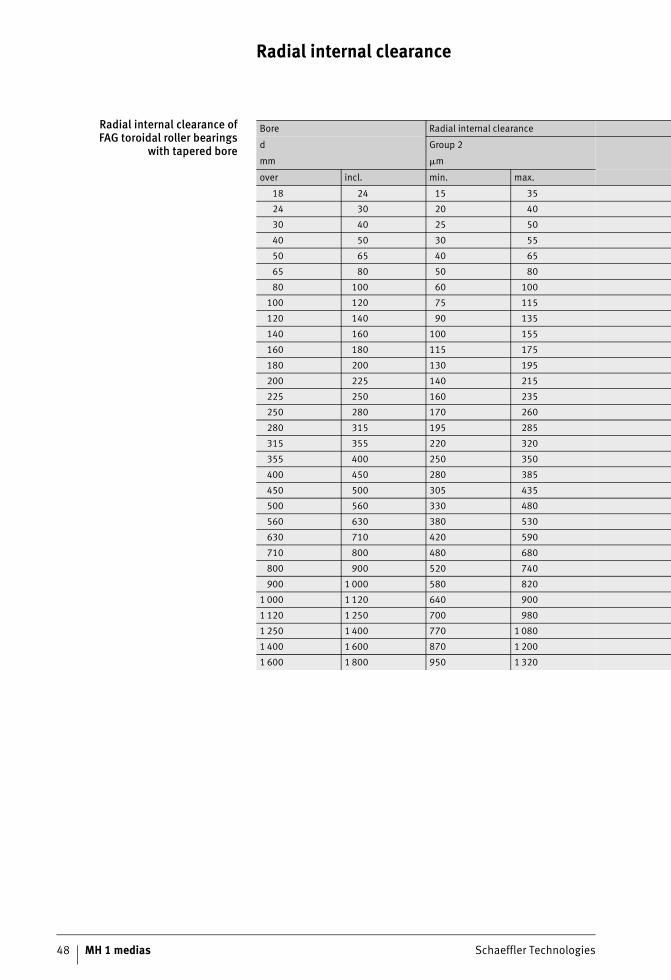
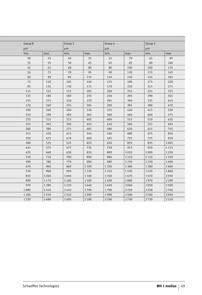
Radial internal clearance ofFAG toroidal roller bearings
with tapered bore
Bore Radial internal clearance
d Group 2
mm �m
over incl. min. max.
18 24 15 35
24 30 20 40
30 40 25 50
40 50 30 55
50 65 40 65
65 80 50 80
80 100 60 100
100 120 75 115
120 140 90 135
140 160 100 155
160 180 115 175
180 200 130 195
200 225 140 215
225 250 160 235
250 280 170 260
280 315 195 285
315 355 220 320
355 400 250 350
400 450 280 385
450 500 305 435
500 560 330 480
560 630 380 530
630 710 420 590
710 800 480 680
800 900 520 740
900 1 000 580 820
1 000 1 120 640 900
1 120 1 250 700 980
1 250 1 400 770 1 080
1 400 1 600 870 1 200
1 600 1 800 950 1 320
Schaeffler Technologies MH 1 medias 49
Group N Group 3 Group 4 Group 5
�m �m �m �m
min. max. min. max. min. max. min. max.
30 45 40 55 55 70 65 85
35 55 50 65 65 85 80 100
45 65 60 80 80 100 100 125
50 75 70 95 90 120 115 145
60 90 85 115 110 150 145 185
75 110 105 140 135 180 175 220
95 135 130 175 170 220 215 275
115 155 155 205 200 255 255 325
135 180 180 235 230 295 290 365
155 215 210 270 265 340 335 415
170 240 235 305 300 385 380 470
190 260 260 330 325 420 415 520
210 290 285 365 360 460 460 575
235 315 315 405 400 515 510 635
255 345 340 445 440 560 555 695
280 380 375 485 480 620 615 765
315 420 415 545 540 680 675 850
350 475 470 600 595 755 755 920
380 525 525 655 650 835 835 1 005
435 575 575 735 730 915 910 1 115
470 640 630 810 800 1 010 1 000 1 230
530 710 700 890 880 1 110 1 110 1 350
590 780 770 990 980 1 230 1 230 1 490
670 860 860 1 100 1 100 1 380 1 380 1 660
730 960 950 1 220 1 210 1 530 1 520 1 860
810 1 040 1 040 1 340 1 340 1 670 1 670 2 050
890 1 170 1 160 1 500 1 490 1 880 1 870 2 280
970 1 280 1 270 1 640 1 630 2 060 2 050 2 500
1 080 1 410 1 410 1 790 1 780 2 250 2 250 2 740
1 200 1 550 1 550 1 990 1 990 2 500 2 500 3 050
1 320 1 690 1 690 2 180 2 180 2 730 2 730 3 310
50 MH 1 medias Schaeffler Technologies
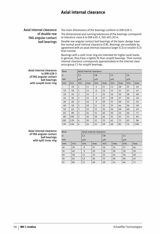
Axial internal clearance
Axial internal clearanceof double row
FAG angular contactball bearings
The main dimensions of the bearings conform to DIN 628-3.The dimensional and running tolerances of the bearings correspond to tolerance class 6 to DIN 620-2, ISO 492:2014.Double row angular contact ball bearings of the basic design have the normal axial internal clearance (CN). Bearings are available by agreement with an axial internal clearance larger (C3) or smaller (C2) than normal.Bearings with a split inner ring are intended for higher axial loads.In general, they have a tighter fit than unsplit bearings. Their normal internal clearance corresponds approximately to the internal clear-ance group C3 for unsplit bearings.
Axial internal clearanceto DIN 628-3
of FAG angular contactball bearings
with unsplit inner ring
Axial internal clearanceof FAG angular contact
ball bearingswith split inner ring
Bore Axial internal clearance
d C2 CN C3 C4
mm �m �m �m �m
over incl. min. max. min. max. min. max. min. max.
– 10 1 11 5 21 12 28 25 45
10 18 1 12 6 23 13 31 27 47
18 24 2 14 7 25 16 34 28 48
24 30 2 15 8 27 18 37 30 50
30 40 2 16 9 29 21 40 33 54
40 50 2 18 11 33 23 44 36 58
50 65 3 22 13 36 26 48 40 63
65 80 3 24 15 40 30 54 46 71
80 100 3 26 18 46 35 63 55 83
100 120 4 30 22 53 42 73 65 96
120 140 4 34 25 59 48 82 74 108
Bore Axial internal clearance
d C2 CN C3
mm �m �m �m
over incl. min. max. min. max. min. max.
24 30 8 27 16 35 27 46
30 40 9 29 18 38 30 50
40 50 11 33 22 44 36 58
50 65 13 36 25 48 40 63
65 80 15 40 29 54 46 71
Schaeffler Technologies MH 1 medias 51
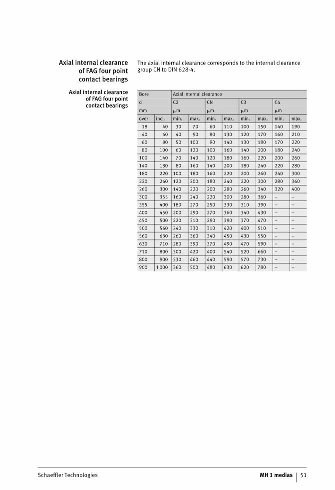
Axial internal clearanceof FAG four pointcontact bearings
The axial internal clearance corresponds to the internal clearance group CN to DIN 628-4.
Axial internal clearanceof FAG four pointcontact bearings
Bore Axial internal clearance
d C2 CN C3 C4
mm �m �m �m �m
over incl. min. max. min. max. min. max. min. max.
18 40 30 70 60 110 100 150 140 190
40 60 40 90 80 130 120 170 160 210
60 80 50 100 90 140 130 180 170 220
80 100 60 120 100 160 140 200 180 240
100 140 70 140 120 180 160 220 200 260
140 180 80 160 140 200 180 240 220 280
180 220 100 180 160 220 200 260 240 300
220 260 120 200 180 240 220 300 280 360
260 300 140 220 200 280 260 340 320 400
300 355 160 240 220 300 280 360 – –
355 400 180 270 250 330 310 390 – –
400 450 200 290 270 360 340 430 – –
450 500 220 310 290 390 370 470 – –
500 560 240 330 310 420 400 510 – –
560 630 260 360 340 450 430 550 – –
630 710 280 390 370 490 470 590 – –
710 800 300 420 400 540 520 660 – –
800 900 330 460 440 590 570 730 – –
900 1 000 360 500 480 630 620 780 – –
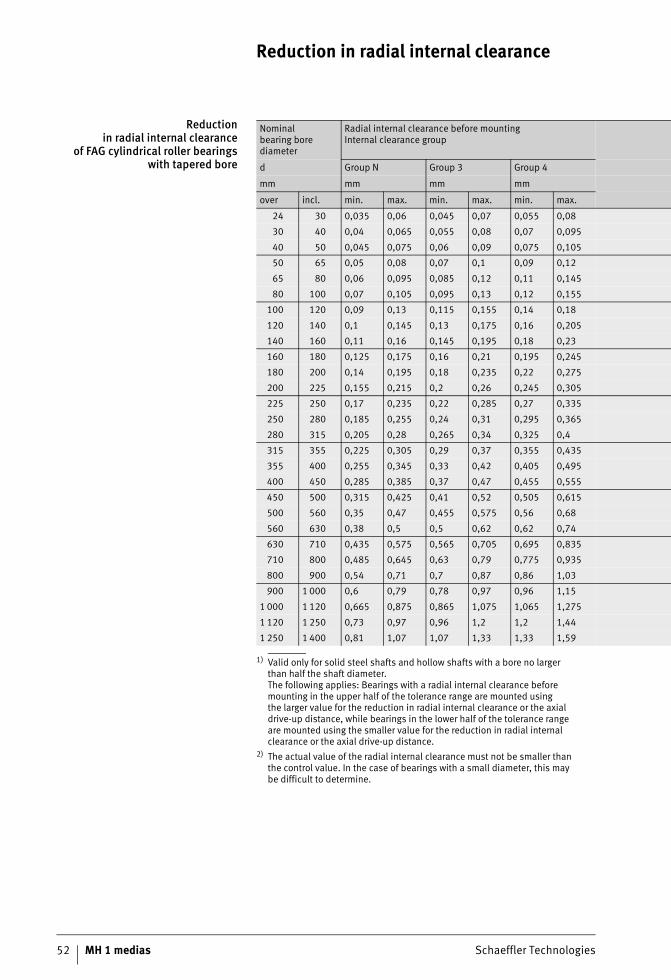
52 MH 1 medias Schaeffler Technologies
Reduction in radial internal clearance
Reductionin radial internal clearance
of FAG cylindrical roller bearingswith tapered bore
1) Valid only for solid steel shafts and hollow shafts with a bore no largerthan half the shaft diameter.The following applies: Bearings with a radial internal clearance beforemounting in the upper half of the tolerance range are mounted usingthe larger value for the reduction in radial internal clearance or the axialdrive-up distance, while bearings in the lower half of the tolerance rangeare mounted using the smaller value for the reduction in radial internalclearance or the axial drive-up distance.
2) The actual value of the radial internal clearance must not be smaller thanthe control value. In the case of bearings with a small diameter, this maybe difficult to determine.
Nominalbearing bore diameter
Radial internal clearance before mountingInternal clearance group
d Group N Group 3 Group 4
mm mm mm mm
over incl. min. max. min. max. min. max.
24 30 0,035 0,06 0,045 0,07 0,055 0,08
30 40 0,04 0,065 0,055 0,08 0,07 0,095
40 50 0,045 0,075 0,06 0,09 0,075 0,105
50 65 0,05 0,08 0,07 0,1 0,09 0,12
65 80 0,06 0,095 0,085 0,12 0,11 0,145
80 100 0,07 0,105 0,095 0,13 0,12 0,155
100 120 0,09 0,13 0,115 0,155 0,14 0,18
120 140 0,1 0,145 0,13 0,175 0,16 0,205
140 160 0,11 0,16 0,145 0,195 0,18 0,23
160 180 0,125 0,175 0,16 0,21 0,195 0,245
180 200 0,14 0,195 0,18 0,235 0,22 0,275
200 225 0,155 0,215 0,2 0,26 0,245 0,305
225 250 0,17 0,235 0,22 0,285 0,27 0,335
250 280 0,185 0,255 0,24 0,31 0,295 0,365
280 315 0,205 0,28 0,265 0,34 0,325 0,4
315 355 0,225 0,305 0,29 0,37 0,355 0,435
355 400 0,255 0,345 0,33 0,42 0,405 0,495
400 450 0,285 0,385 0,37 0,47 0,455 0,555
450 500 0,315 0,425 0,41 0,52 0,505 0,615
500 560 0,35 0,47 0,455 0,575 0,56 0,68
560 630 0,38 0,5 0,5 0,62 0,62 0,74
630 710 0,435 0,575 0,565 0,705 0,695 0,835
710 800 0,485 0,645 0,63 0,79 0,775 0,935
800 900 0,54 0,71 0,7 0,87 0,86 1,03
900 1 000 0,6 0,79 0,78 0,97 0,96 1,15
1 000 1 120 0,665 0,875 0,865 1,075 1,065 1,275
1 120 1 250 0,73 0,97 0,96 1,2 1,2 1,44
1 250 1 400 0,81 1,07 1,07 1,33 1,33 1,59

Schaeffler Technologies MH 1 medias 53
Reductionin radial internal clearance1)
Drive-up distance on taper 1:121) Control value for radial internal clearance after mounting2)
Shaft Sleeve Group N Group 3 Group 4
mm mm mm mm mm mm
min. max. min. max. min. max. min. min. min.
0,015 0,02 0,3 0,35 0,3 0,4 0,02 0,025 0,035
0,02 0,025 0,35 0,4 0,35 0,45 0,02 0,025 0,04
0,025 0,03 0,4 0,45 0,45 0,5 0,02 0,03 0,045
0,03 0,035 0,45 0,55 0,5 0,65 0,02 0,035 0,05
0,035 0,04 0,55 0,6 0,65 0,7 0,025 0,04 0,07
0,04 0,045 0,6 0,7 0,65 0,8 0,03 0,05 0,075
0,045 0,055 0,7 0,85 0,8 0,95 0,045 0,065 0,085
0,055 0,065 0,85 1 0,95 1,1 0,045 0,07 0,095
0,06 0,075 0,9 1,2 1,1 1,3 0,05 0,075 0,105
0,065 0,085 1 1,3 1,3 1,5 0,06 0,08 0,11
0,075 0,095 1,2 1,5 1,4 1,7 0,065 0,09 0,125
0,085 0,105 1,3 1,6 1,6 1,8 0,07 0,1 0,14
0,095 0,115 1,5 1,8 1,7 2 0,075 0,105 0,155
0,105 0,125 1,6 2 1,9 2,3 0,08 0,125 0,17
0,115 0,14 1,8 2,2 2,2 2,4 0,09 0,13 0,185
0,13 0,16 2 2,5 2,5 2,7 0,095 0,14 0,195
0,14 0,17 2,2 2,6 2,6 2,9 0,115 0,165 0,235
0,15 0,185 2,3 2,8 2,8 3,1 0,135 0,19 0,27
0,16 0,195 2,5 3 3,1 3,4 0,155 0,215 0,31
0,17 0,215 2,7 3,4 3,5 3,8 0,18 0,24 0,345
0,185 0,24 2,9 3,7 3,6 4,2 0,195 0,26 0,38
0,2 0,26 3,1 4,1 3,9 4,7 0,235 0,305 0,435
0,22 0,28 3,4 4,4 4,3 5,3 0,26 0,35 0,495
0,24 0,31 3,7 4,8 4,8 5,5 0,3 0,39 0,55
0,26 0,34 4,1 5,3 5,2 6,2 0,34 0,44 0,62
0,28 0,37 4,4 5,8 5,7 7 0,385 0,5 0,7
0,31 0,41 4,8 6,4 6,3 7,6 0,42 0,55 0,79
0,34 0,45 5,3 7 0,3 8,3 0,47 0,62 0,85
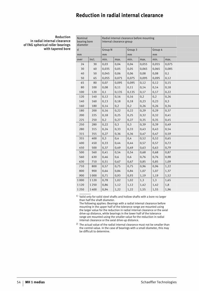
Reduction in radial internal clearance
54 MH 1 medias Schaeffler Technologies
Reductionin radial internal clearance
of FAG spherical roller bearingswith tapered bore
1) Valid only for solid steel shafts and hollow shafts with a bore no largerthan half the shaft diameter.The following applies: Bearings with a radial internal clearance beforemounting in the upper half of the tolerance range are mounted usingthe larger value for the reduction in radial internal clearance or the axialdrive-up distance, while bearings in the lower half of the tolerancerange are mounted using the smaller value for the reduction in radialinternal clearance or the axial drive-up distance.
2) The actual value of the radial internal clearance must not be smaller thanthe control value. In the case of bearings with a small diameter, this maybe difficult to determine.
Nominalbearing bore diameter
Radial internal clearance before mountingInternal clearance group
d Group N Group 3 Group 4
mm mm mm mm
over incl. min. max. min. max. min. max.
24 30 0,03 0,04 0,04 0,055 0,055 0,075
30 40 0,035 0,05 0,05 0,065 0,065 0,085
40 50 0,045 0,06 0,06 0,08 0,08 0,1
50 65 0,055 0,075 0,075 0,095 0,095 0,12
65 80 0,07 0,095 0,095 0,12 0,12 0,15
80 100 0,08 0,11 0,11 0,14 0,14 0,18
100 120 0,1 0,135 0,135 0,17 0,17 0,22
120 140 0,12 0,16 0,16 0,2 0,2 0,26
140 160 0,13 0,18 0,18 0,23 0,23 0,3
160 180 0,14 0,2 0,2 0,26 0,26 0,34
180 200 0,16 0,22 0,22 0,29 0,29 0,37
200 225 0,18 0,25 0,25 0,32 0,32 0,41
225 250 0,2 0,27 0,27 0,35 0,35 0,45
250 280 0,22 0,3 0,3 0,39 0,39 0,49
280 315 0,24 0,33 0,33 0,43 0,43 0,54
315 355 0,27 0,36 0,36 0,47 0,47 0,59
355 400 0,3 0,4 0,4 0,52 0,52 0,65
400 450 0,33 0,44 0,44 0,57 0,57 0,72
450 500 0,37 0,49 0,49 0,63 0,63 0,79
500 560 0,41 0,54 0,54 0,68 0,68 0,87
560 630 0,46 0,6 0,6 0,76 0,76 0,98
630 710 0,51 0,67 0,67 0,85 0,85 1,09
710 800 0,57 0,75 0,75 0,96 0,96 1,22
800 900 0,64 0,84 0,84 1,07 1,07 1,37
900 1 000 0,71 0,93 0,93 1,19 1,19 1,52
1 000 1 120 0,78 1,02 1,02 1,3 1,3 1,65
1 120 1 250 0,86 1,12 1,12 1,42 1,42 1,8
1 250 1 400 0,94 1,22 1,22 1,55 1,55 1,96

Schaeffler Technologies MH 1 medias 55
Reductionin radial internal clearance1)
Drive-up distance on taper 1:121) Drive-up distance on taper 1:301) Control valuefor radial internal clearance after mounting2)
Shaft Sleeve Shaft Sleeve Group N Group 3 Group 4
mm mm mm mm mm mm mm mm
min. max. min. max. min. max. min. max. min. max. min. min. min.
0,015 0,02 0,3 0,35 0,3 0,4 – – – – 0,015 0,02 0,035
0,02 0,025 0,35 0,4 0,35 0,45 – – – – 0,015 0,025 0,04
0,025 0,03 0,4 0,45 0,45 0,5 – – – – 0,02 0,03 0,05
0,03 0,04 0,45 0,6 0,5 0,7 – – – – 0,025 0,035 0,055
0,04 0,05 0,6 0,75 0,7 0,85 – – – – 0,025 0,04 0,07
0,045 0,06 0,7 0,9 0,75 1 1,7 2,2 1,8 2,4 0,035 0,05 0,08
0,05 0,07 0,7 1,1 0,8 1,2 1,9 2,7 2 2,8 0,05 0,065 0,1
0,065 0,09 1,1 1,4 1,2 1,5 2,7 3,5 2,8 3,6 0,055 0,08 0,11
0,075 0,1 1,2 1,6 1,3 1,7 3 4 3,1 4,2 0,055 0,09 0,13
0,08 0,11 1,3 1,7 1,4 1,9 3,2 4,2 3,3 4,6 0,06 0,1 0,15
0,09 0,13 1,4 2 1,5 2,2 3,5 4,5 3,6 5 0,07 0,1 0,16
0,1 0,14 1,6 2,2 1,7 2,4 4 5,5 4,2 5,7 0,08 0,12 0,18
0,11 0,15 1,7 2,4 1,8 2,6 4,2 6 4,6 6,2 0,09 0,13 0,2
0,12 0,17 1,9 2,6 2 2,9 4,7 6,7 4,8 6,9 0,1 0,14 0,22
0,13 0,19 2 3 2,2 3,2 5 7,5 5,2 7,7 0,11 0,15 0,24
0,15 0,21 2,4 3,4 2,6 3,6 6 8,2 6,2 8,4 0,12 0,17 0,26
0,17 0,23 2,6 3,6 2,9 3,9 6,5 9 5,8 9,2 0,13 0,19 0,29
0,2 0,26 3,1 4,1 3,4 4,4 7,7 10 8 10,4 0,13 0,2 0,31
0,21 0,28 3,3 4,4 3,6 4,8 8,2 11 8,4 11,2 0,16 0,23 0,35
0,24 0,32 3,7 5 4,1 5,4 9,2 12,5 9,6 12,8 0,17 0,25 0,36
0,26 0,35 4 5,4 4,4 5,9 10 13,5 10,4 14 0,2 0,29 0,41
0,3 0,4 4,6 6,2 5,1 6,8 11,5 15,5 12 16 0,21 0,31 0,45
0,34 0,45 5,3 7 5,8 7,6 13,3 17,5 13,6 18 0,23 0,35 0,51
0,37 0,5 5,7 7,8 6,3 8,5 14,3 19,5 14,8 20 0,27 0,39 0,57
0,41 0,55 6,3 8,5 7 9,4 15,8 21 16,4 22 0,3 0,43 0,64
0,45 0,6 6,8 9 7,6 10,2 17 23 18 24 0,32 0,48 0,7
0,49 0,65 7,4 9,8 8,3 11 18,5 25 19,6 26 0,34 0,54 0,77
0,55 0,72 8,3 10,8 9,3 12,1 21 27 22,2 28,3 0,36 0,59 0,84
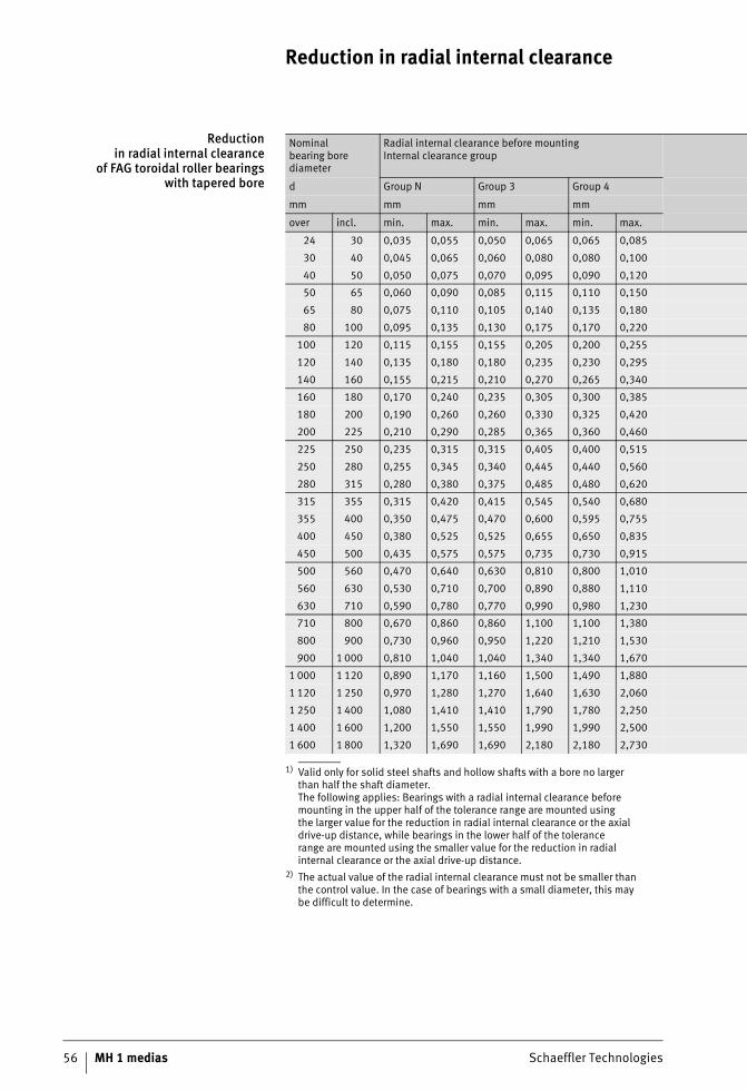
Reduction in radial internal clearance
56 MH 1 medias Schaeffler Technologies
Reductionin radial internal clearance
of FAG toroidal roller bearingswith tapered bore
1) Valid only for solid steel shafts and hollow shafts with a bore no largerthan half the shaft diameter.The following applies: Bearings with a radial internal clearance beforemounting in the upper half of the tolerance range are mounted usingthe larger value for the reduction in radial internal clearance or the axialdrive-up distance, while bearings in the lower half of the tolerancerange are mounted using the smaller value for the reduction in radialinternal clearance or the axial drive-up distance.
2) The actual value of the radial internal clearance must not be smaller thanthe control value. In the case of bearings with a small diameter, this maybe difficult to determine.
Nominalbearing bore diameter
Radial internal clearance before mountingInternal clearance group
d Group N Group 3 Group 4
mm mm mm mm
over incl. min. max. min. max. min. max.
24 30 0,035 0,055 0,050 0,065 0,065 0,085
30 40 0,045 0,065 0,060 0,080 0,080 0,100
40 50 0,050 0,075 0,070 0,095 0,090 0,120
50 65 0,060 0,090 0,085 0,115 0,110 0,150
65 80 0,075 0,110 0,105 0,140 0,135 0,180
80 100 0,095 0,135 0,130 0,175 0,170 0,220
100 120 0,115 0,155 0,155 0,205 0,200 0,255
120 140 0,135 0,180 0,180 0,235 0,230 0,295
140 160 0,155 0,215 0,210 0,270 0,265 0,340
160 180 0,170 0,240 0,235 0,305 0,300 0,385
180 200 0,190 0,260 0,260 0,330 0,325 0,420
200 225 0,210 0,290 0,285 0,365 0,360 0,460
225 250 0,235 0,315 0,315 0,405 0,400 0,515
250 280 0,255 0,345 0,340 0,445 0,440 0,560
280 315 0,280 0,380 0,375 0,485 0,480 0,620
315 355 0,315 0,420 0,415 0,545 0,540 0,680
355 400 0,350 0,475 0,470 0,600 0,595 0,755
400 450 0,380 0,525 0,525 0,655 0,650 0,835
450 500 0,435 0,575 0,575 0,735 0,730 0,915
500 560 0,470 0,640 0,630 0,810 0,800 1,010
560 630 0,530 0,710 0,700 0,890 0,880 1,110
630 710 0,590 0,780 0,770 0,990 0,980 1,230
710 800 0,670 0,860 0,860 1,100 1,100 1,380
800 900 0,730 0,960 0,950 1,220 1,210 1,530
900 1 000 0,810 1,040 1,040 1,340 1,340 1,670
1 000 1 120 0,890 1,170 1,160 1,500 1,490 1,880
1 120 1 250 0,970 1,280 1,270 1,640 1,630 2,060
1 250 1 400 1,080 1,410 1,410 1,790 1,780 2,250
1 400 1 600 1,200 1,550 1,550 1,990 1,990 2,500
1 600 1 800 1,320 1,690 1,690 2,180 2,180 2,730
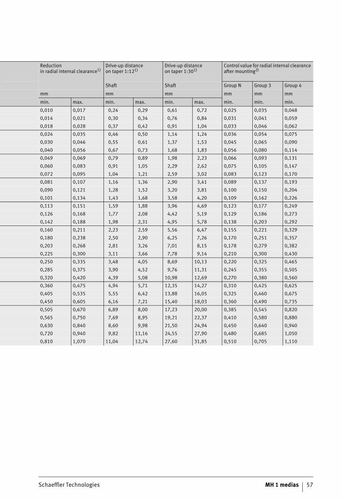
Schaeffler Technologies MH 1 medias 57
Reductionin radial internal clearance1)
Drive-up distanceon taper 1:121)
Drive-up distanceon taper 1:301)
Control value for radial internal clearance after mounting2)
Shaft Shaft Group N Group 3 Group 4
mm mm mm mm mm mm
min. max. min. max. min. max. min. min. min.
0,010 0,017 0,24 0,29 0,61 0,72 0,025 0,035 0,048
0,014 0,021 0,30 0,34 0,76 0,84 0,031 0,041 0,059
0,018 0,028 0,37 0,42 0,91 1,04 0,033 0,046 0,062
0,024 0,035 0,46 0,50 1,14 1,24 0,036 0,054 0,075
0,030 0,046 0,55 0,61 1,37 1,53 0,045 0,065 0,090
0,040 0,056 0,67 0,73 1,68 1,83 0,056 0,080 0,114
0,049 0,069 0,79 0,89 1,98 2,23 0,066 0,093 0,131
0,060 0,083 0,91 1,05 2,29 2,62 0,075 0,105 0,147
0,072 0,095 1,04 1,21 2,59 3,02 0,083 0,123 0,170
0,081 0,107 1,16 1,36 2,90 3,41 0,089 0,137 0,193
0,090 0,121 1,28 1,52 3,20 3,81 0,100 0,150 0,204
0,101 0,134 1,43 1,68 3,58 4,20 0,109 0,162 0,226
0,113 0,151 1,59 1,88 3,96 4,69 0,123 0,177 0,249
0,126 0,168 1,77 2,08 4,42 5,19 0,129 0,186 0,273
0,142 0,188 1,98 2,31 4,95 5,78 0,138 0,203 0,292
0,160 0,211 2,23 2,59 5,56 6,47 0,155 0,221 0,329
0,180 0,238 2,50 2,90 6,25 7,26 0,170 0,251 0,357
0,203 0,268 2,81 3,26 7,01 8,15 0,178 0,279 0,382
0,225 0,300 3,11 3,66 7,78 9,14 0,210 0,300 0,430
0,250 0,335 3,48 4,05 8,69 10,13 0,220 0,325 0,465
0,285 0,375 3,90 4,52 9,76 11,31 0,245 0,355 0,505
0,320 0,420 4,39 5,08 10,98 12,69 0,270 0,380 0,560
0,360 0,475 4,94 5,71 12,35 14,27 0,310 0,425 0,625
0,405 0,535 5,55 6,42 13,88 16,05 0,325 0,460 0,675
0,450 0,605 6,16 7,21 15,40 18,03 0,360 0,490 0,735
0,505 0,670 6,89 8,00 17,23 20,00 0,385 0,545 0,820
0,565 0,750 7,69 8,95 19,21 22,37 0,410 0,580 0,880
0,630 0,840 8,60 9,98 21,50 24,94 0,450 0,640 0,940
0,720 0,940 9,82 11,16 24,55 27,90 0,480 0,685 1,050
0,810 1,070 11,04 12,74 27,60 31,85 0,510 0,705 1,110
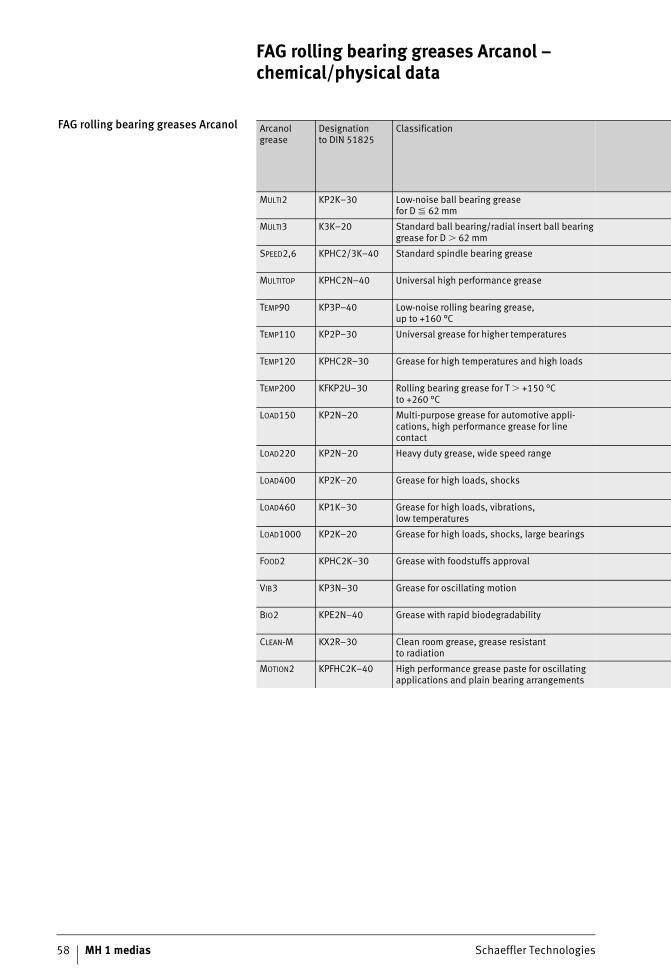
58 MH 1 medias Schaeffler Technologies
FAG rolling bearing greases Arcanol – chemical/physical data
FAG rolling bearing greases Arcanol Arcanol grease
Designationto DIN 51825
Classification
MULTI2 KP2K–30 Low-noise ball bearing greasefor D � 62 mm
MULTI3 K3K–20 Standard ball bearing/radial insert ball bearing grease for D � 62 mm
SPEED2,6 KPHC2/3K–40 Standard spindle bearing grease
MULTITOP KPHC2N–40 Universal high performance grease
TEMP90 KP3P–40 Low-noise rolling bearing grease,up to +160 °C
TEMP110 KP2P–30 Universal grease for higher temperatures
TEMP120 KPHC2R–30 Grease for high temperatures and high loads
TEMP200 KFKP2U–30 Rolling bearing grease for T � +150 °C to +260 °C
LOAD150 KP2N–20 Multi-purpose grease for automotive appli-cations, high performance grease for line contact
LOAD220 KP2N–20 Heavy duty grease, wide speed range
LOAD400 KP2K–20 Grease for high loads, shocks
LOAD460 KP1K–30 Grease for high loads, vibrations,low temperatures
LOAD1000 KP2K–20 Grease for high loads, shocks, large bearings
FOOD2 KPHC2K–30 Grease with foodstuffs approval
VIB3 KP3N–30 Grease for oscillating motion
BIO2 KPE2N–40 Grease with rapid biodegradability
CLEAN-M KX2R–30 Clean room grease, grease resistantto radiation
MOTION2 KPFHC2K–40 High performance grease paste for oscillating applications and plain bearing arrangements
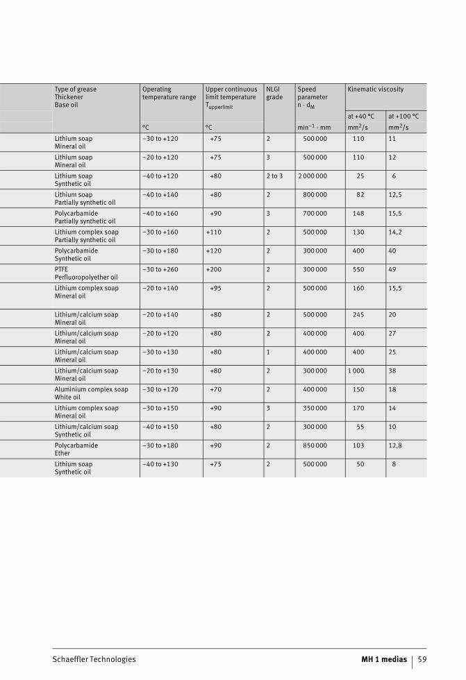
Schaeffler Technologies MH 1 medias 59
Type of greaseThickenerBase oil
Operating temperature range
Upper continuous limit temperatureTupperlimit
NLGI grade
Speed parametern · dM
Kinematic viscosity
at +40 °C at +100 °C
°C °C min–1 · mm mm2/s mm2/s
Lithium soapMineral oil
–30 to +120 +75 2 500 000 110 11
Lithium soapMineral oil
–20 to +120 +75 3 500 000 110 12
Lithium soapSynthetic oil
–40 to +120 +80 2 to 3 2 000 000 25 6
Lithium soapPartially synthetic oil
–40 to +140 +80 2 800 000 82 12,5
PolycarbamidePartially synthetic oil
–40 to +160 +90 3 700 000 148 15,5
Lithium complex soapPartially synthetic oil
–30 to +160 +110 2 500 000 130 14,2
PolycarbamideSynthetic oil
–30 to +180 +120 2 300 000 400 40
PTFEPerfluoropolyether oil
–30 to +260 +200 2 300 000 550 49
Lithium complex soapMineral oil
–20 to +140 +95 2 500 000 160 15,5
Lithium/calcium soapMineral oil
–20 to +140 +80 2 500 000 245 20
Lithium/calcium soapMineral oil
–20 to +120 +80 2 400 000 400 27
Lithium/calcium soapMineral oil
–30 to +130 +80 1 400 000 400 25
Lithium/calcium soapMineral oil
–20 to +130 +80 2 300 000 1 000 38
Aluminium complex soapWhite oil
–30 to +120 +70 2 400 000 150 18
Lithium complex soapMineral oil
–30 to +150 +90 3 350 000 170 14
Lithium/calcium soapSynthetic oil
–40 to +150 +80 2 300 000 55 10
PolycarbamideEther
–30 to +180 +90 2 850 000 103 12,8
Lithium soapSynthetic oil
–40 to +130 +75 2 500 000 50 8
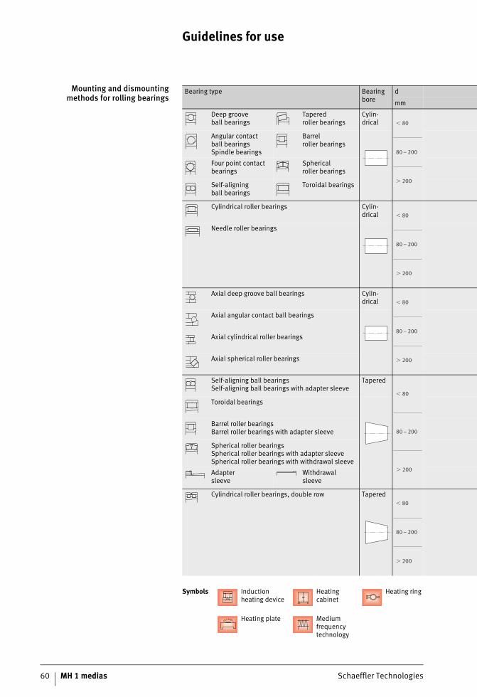
60 MH 1 medias Schaeffler Technologies
Guidelines for use
Mounting and dismountingmethods for rolling bearings
Bearing type Bearing bore
d
mm
Deep grooveball bearings
Taperedroller bearings
Cylin-drical
Angular contactball bearingsSpindle bearings
Barrelroller bearings
Four point contact bearings
Sphericalroller bearings
Self-aligningball bearings
Toroidal bearings
Cylindrical roller bearings Cylin-drical
Needle roller bearings
Axial deep groove ball bearings Cylin-drical
Axial angular contact ball bearings
Axial cylindrical roller bearings
Axial spherical roller bearings
Self-aligning ball bearingsSelf-aligning ball bearings with adapter sleeve
Tapered
Toroidal bearings
Barrel roller bearingsBarrel roller bearings with adapter sleeve
Spherical roller bearingsSpherical roller bearings with adapter sleeveSpherical roller bearings with withdrawal sleeve
Adaptersleeve
Withdrawalsleeve
Cylindrical roller bearings, double row Tapered
Symbols Induction heating device
Heating cabinet
Heating ring
Heating plate Medium frequency technology
� 80
80 – 200
� 200
� 80
80 – 200
� 200
� 80
80 – 200
� 200
� 80
80 – 200
� 200
� 80
80 – 200
� 200
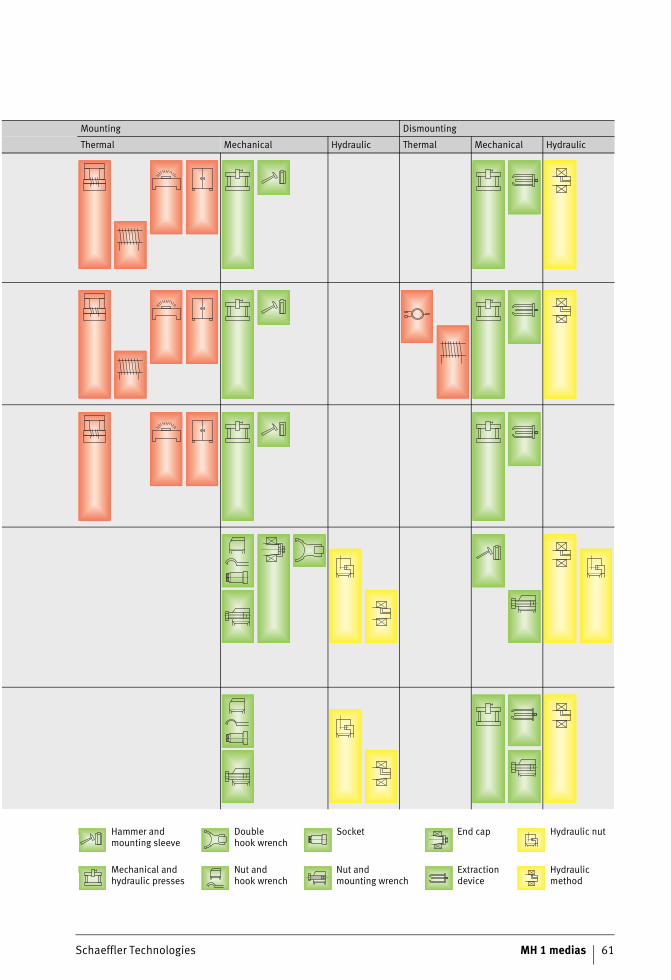
Schaeffler Technologies MH 1 medias 61
Mounting Dismounting
Thermal Mechanical Hydraulic Thermal Mechanical Hydraulic
Hammer and mounting sleeve
Doublehook wrench
Socket End cap Hydraulic nut
Mechanical and hydraulic presses
Nut andhook wrench
Nut andmounting wrench
Extraction device
Hydraulic method
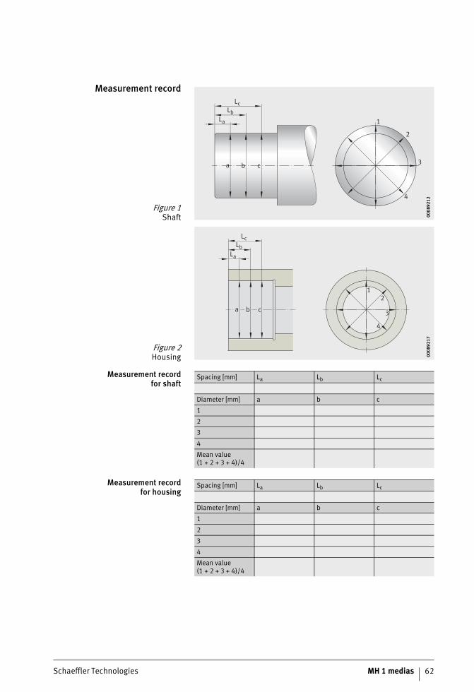
Schaeffler Technologies MH 1 medias 62
Measurement record
Measurement recordfor shaft
Measurement recordfor housing
Figure 1Shaft
a b c
1
2
3
4
La
Lb
Lc
0008
9212
0008
9212
Figure 2Housing
La
Lb
Lc
a b c
12
3
4
0008
9217
0008
9217
Spacing [mm] La Lb Lc
Diameter [mm] a b c
1
2
3
4
Mean value (1 + 2 + 3 + 4)/4
Spacing [mm] La Lb Lc
Diameter [mm] a b c
1
2
3
4
Mean value (1 + 2 + 3 + 4)/4

64 MH 1 medias Schaeffler Technologies
Further information
Further information This PDF file is part of “medias” (medias.schaeffler.de). Please also take note of all other information provided there (Internet pages, PDF files), where this information is applicable to your task.?

Schaeffler TechnologiesAG & Co. KG
Industriestraße 1–391074 HerzogenaurachGermanyInternet www.schaeffler.de/enE-mail [email protected]
In Germany:Phone 0180 5003872Fax 0180 5003873
From other countries:Phone +49 9132 82-0Fax +49 9132 82-4950
Schaeffler TechnologiesAG & Co. KG
Georg-Schäfer-Straße 3097421 SchweinfurtGermanyInternet www.schaeffler.de/enE-mail [email protected]
In Germany:Phone 0180 5003872Fax 0180 5003873
From other countries:Phone +49 9721 91-0Fax +49 9721 91-3435
Every care has been taken to ensure the
correctness of the information contained
in this publication but no liability can
be accepted for any errors or omissions.
We reserve the right to make technical
changes.
© Schaeffler Technologies AG & Co. KG
Issued: 2017, September
This publication or parts thereof may not
be reproduced without our permission.
MH 1 GB-DMH
1 m
edia
s /
GB-
D /
pub
lishe
d 20
1603
31 /
cre
ated
201
7092
7 /
Recommended


![Modeling of Piston Ring-Cylinder Bore-Piston 2015-01-1724 ...kharazm1/assets/piston.pdf · configurations' impact on oil consumption and blowby [16]. However, the ring-cylinder bore](https://img.pdfslide.net/doc/110x75/5b5bd7487f8b9a68368b7e3f/modeling-of-piston-ring-cylinder-bore-piston-2015-01-1724-kharazm1assets-.jpg)