Storage Tank Design as per
IS 803 / API 650

Storage Tank ClassificationStorage Tank Classification A storage tank is a construction or a container, A storage tank is a construction or a container,
usually holding liquid's, sometimes for gases.usually holding liquid's, sometimes for gases. According to NFPA (National Fire Protection According to NFPA (National Fire Protection
Association), atmospheric storage tanks are Association), atmospheric storage tanks are defined as those tanks that are designed to defined as those tanks that are designed to operate at pressure between atmospheric operate at pressure between atmospheric pressure and 6.9 Kpa gage, as measured at the pressure and 6.9 Kpa gage, as measured at the top of the tank.top of the tank.
Such tanks are builds in two basic design – the Such tanks are builds in two basic design – the fixed roof design & External floating roof design.fixed roof design & External floating roof design.
Storage Tank Classification Storage Tank Classification (Contd.)(Contd.)
Fixed roof design:Fixed roof design:Fixed-roof tanksFixed-roof tanks consist of a cylindrical shell with a permanently welded consist of a cylindrical shell with a permanently welded roof that can be flat, conical or dome-shaped. Such Tanks are used to store roof that can be flat, conical or dome-shaped. Such Tanks are used to store materials with a true vapor pressure of less than 10.3 KPa absolute.materials with a true vapor pressure of less than 10.3 KPa absolute.
External-Floating Roof Design.External-Floating Roof Design.
In floating-roof storage tanks, the roof is made to rest on the stored liquid In floating-roof storage tanks, the roof is made to rest on the stored liquid and is free to move with the level of the liquid. These tanks reduce and is free to move with the level of the liquid. These tanks reduce evaporation losses and control breathing losses while filling. They are evaporation losses and control breathing losses while filling. They are preferred for storage of petroleum products with a true vapor pressure of preferred for storage of petroleum products with a true vapor pressure of 10.3 to 76.5 KPa absolute.10.3 to 76.5 KPa absolute.
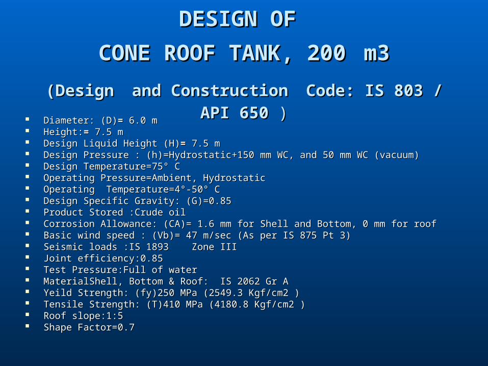
DESIGN OF DESIGN OF
CONE ROOF TANK, 200CONE ROOF TANK, 200 m3m3
(Design(Design and Constructionand Construction Code: IS 803 / API 650Code: IS 803 / API 650 ) ) Diameter: (D)Diameter: (D)= = 6.0 m6.0 m Height:Height:= = 7.5 m7.5 m Design Liquid Height (H)Design Liquid Height (H)= = 7.5 m7.5 m Design Pressure : (h)=Hydrostatic+150 mm WC, and 50 mm WC (vacuum)Design Pressure : (h)=Hydrostatic+150 mm WC, and 50 mm WC (vacuum) Design Temperature=75° CDesign Temperature=75° C Operating Pressure=Ambient, HydrostaticOperating Pressure=Ambient, Hydrostatic Operating Temperature=4°-50° COperating Temperature=4°-50° C Design Specific Gravity: (G)=0.85Design Specific Gravity: (G)=0.85 Product Stored :Crude oilProduct Stored :Crude oil Corrosion Allowance: (CA)= 1.6 mm for Shell and Bottom, 0 mm for roof Corrosion Allowance: (CA)= 1.6 mm for Shell and Bottom, 0 mm for roof Basic wind speed : (Vb)= 47 m/sec (As per IS 875 Pt 3)Basic wind speed : (Vb)= 47 m/sec (As per IS 875 Pt 3) Seismic loads :IS 1893 Zone IIISeismic loads :IS 1893 Zone III Joint efficiency:0.85Joint efficiency:0.85 Test Pressure:Full of waterTest Pressure:Full of water MaterialShell, Bottom & Roof: IS 2062 Gr AMaterialShell, Bottom & Roof: IS 2062 Gr A Yeild Strength: (fy)250 MPa (2549.3 Kgf/cm2 )Yeild Strength: (fy)250 MPa (2549.3 Kgf/cm2 ) Tensile Strength: (T)410 MPa (4180.8 Kgf/cm2 )Tensile Strength: (T)410 MPa (4180.8 Kgf/cm2 ) Roof slope:1:5Roof slope:1:5 Shape Factor=0.7Shape Factor=0.7

Drawing of Storage TankDrawing of Storage Tank
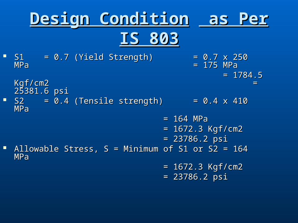
Design ConditionDesign Condition as Per IS 803 as Per IS 803
S1S1 = 0.7 (Yield Strength) = 0.7 (Yield Strength) = 0.7 x 250 MPa = 0.7 x 250 MPa = 175 MPa= 175 MPa
= 1784.5 Kgf/cm2 = 1784.5 Kgf/cm2 = 25381.6 psi = 25381.6 psi
S2S2 = 0.4 (Tensile strength) = 0.4 (Tensile strength) = 0.4 x 410 MPa= 0.4 x 410 MPa
= 164 MPa= 164 MPa= 1672.3 Kgf/cm2= 1672.3 Kgf/cm2= 23786.2 psi= 23786.2 psi
Allowable Stress, S = Minimum of S1 or S2 = 164 MPaAllowable Stress, S = Minimum of S1 or S2 = 164 MPa= 1672.3 Kgf/cm2= 1672.3 Kgf/cm2= 23786.2 psi = 23786.2 psi
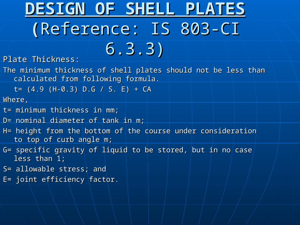
DESIGN OF SHELL PLATESDESIGN OF SHELL PLATES ((Reference: IS 803-CI 6.3.3)Reference: IS 803-CI 6.3.3)
Plate Thickness:Plate Thickness:The minimum thickness of shell plates should not be less than The minimum thickness of shell plates should not be less than
calculated from following formula.calculated from following formula.
t= (4.9 (H-0.3) D.G / S. E) + CAt= (4.9 (H-0.3) D.G / S. E) + CA
Where,Where,
t= minimum thickness in mm;t= minimum thickness in mm;
D= nominal diameter of tank in m;D= nominal diameter of tank in m;
H= height from the bottom of the course under consideration to top H= height from the bottom of the course under consideration to top of curb angle m;of curb angle m;
G= specific gravity of liquid to be stored, but in no case less than 1;G= specific gravity of liquid to be stored, but in no case less than 1;
S= allowable stress; andS= allowable stress; and
E= joint efficiency factor. E= joint efficiency factor.

DESIGN OF SHELL PLATES(contd.)DESIGN OF SHELL PLATES(contd.)
1st Shell Course from bottom1st Shell Course from bottom t1t1 = = ((4.9 (H-0.3) D.G / S. E4.9 (H-0.3) D.G / S. E)) + CA + CA
= (4.9 (7.5-0.3) 6 x 0.85 / (164). (0.85)) + 1.6= (4.9 (7.5-0.3) 6 x 0.85 / (164). (0.85)) + 1.6= 2.89 mm= 2.89 mm
Provide 8 mm thick for 1500 mm height for bottom first Provide 8 mm thick for 1500 mm height for bottom first shell course.shell course.
2nd Shell Course from bottom2nd Shell Course from bottomH = 7.5-1.5 = 6.00 m H = 7.5-1.5 = 6.00 m t2t2 = (4.9 (H-0.3) D.G / S. E) + CA= (4.9 (H-0.3) D.G / S. E) + CA
= (4.9 (6.00-0.3) 6 x 0.85 / (164). = (4.9 (6.00-0.3) 6 x 0.85 / (164). (0.85)) + 1.6(0.85)) + 1.6= 2.62 mm= 2.62 mm
Provide 6 mm thick for 1500 mm height for bottom 2nd Provide 6 mm thick for 1500 mm height for bottom 2nd shell course.shell course.

DESIGN OF SHELL PLATES(contd.)DESIGN OF SHELL PLATES(contd.)
3rd Shell course3rd Shell course H H = 7.5-3 = 4.5 m= 7.5-3 = 4.5 m t3 = t3 = ((4.9 (4.9 (H-0.3) D.G / S. EH-0.3) D.G / S. E)) + CA + CA
= (4.9 (4.5-0.3) 6 x 0.85 / (164). (0.85)) + 1.6= (4.9 (4.5-0.3) 6 x 0.85 / (164). (0.85)) + 1.6 = 2.35 mm= 2.35 mm
Provide 6 mm thick for 1500 mm height for 3rd shell Provide 6 mm thick for 1500 mm height for 3rd shell course.course.
4th Shell course4th Shell courseH H = 7.5-4.5 = 3.0 m= 7.5-4.5 = 3.0 mt4t4 = = ((4.9 (H-0.3) D.G / S. E4.9 (H-0.3) D.G / S. E)) + CA + CA
= (4.9 (3.0-0.3) 6 x 0.85 / (164). (0.85)) + 1.6= (4.9 (3.0-0.3) 6 x 0.85 / (164). (0.85)) + 1.6= 2.22 mm= 2.22 mm
Provide 6 mm thick for 1500 mm height for 4th shellProvide 6 mm thick for 1500 mm height for 4th shell course.course.
DESIGN OF SHELL PLATES(contd.)DESIGN OF SHELL PLATES(contd.)
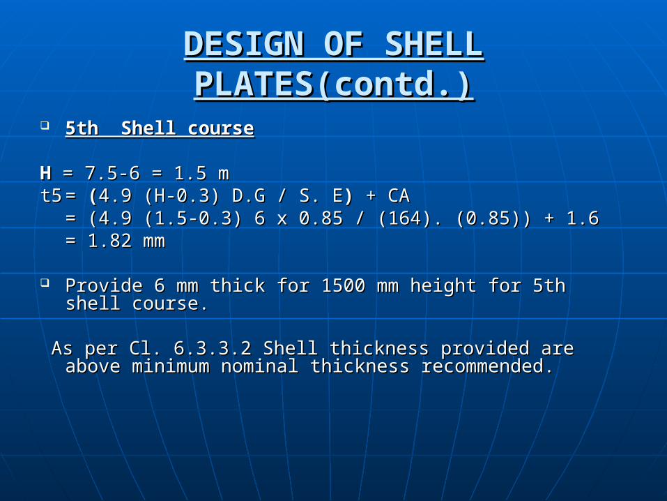
5th Shell course5th Shell course H H = 7.5-6 = 1.5 m= 7.5-6 = 1.5 mt5t5 = = ((4.9 (H-0.3) D.G / S. E4.9 (H-0.3) D.G / S. E)) + CA + CA
= (4.9 (1.5-0.3) 6 x 0.85 / (164). (0.85)) + 1.6= (4.9 (1.5-0.3) 6 x 0.85 / (164). (0.85)) + 1.6= 1.82 mm= 1.82 mm
Provide 6 mm thick for 1500 mm height for 5th shell Provide 6 mm thick for 1500 mm height for 5th shell course.course.
As per Cl. 6.3.3.2 Shell thickness provided are above As per Cl. 6.3.3.2 Shell thickness provided are above minimum nominal thickness recommended.minimum nominal thickness recommended.
DESIGN OF SHELL PLATES(contd.)DESIGN OF SHELL PLATES(contd.)
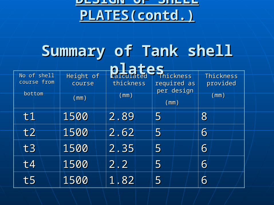
Summary of Tank shell platesSummary of Tank shell platesNo of shell No of shell
course from course from
bottombottom
Height of Height of coursecourse
(mm)(mm)
Calculated Calculated thickness thickness
(mm)(mm)
Thickness Thickness required as required as per design per design
(mm)(mm)
Thickness Thickness provided provided
(mm)(mm)
t1t1 15001500 2.892.89 55 88
t2t2 15001500 2.622.62 55 66
t3t3 15001500 2.352.35 55 66
t4t4 15001500 2.22.2 55 66
t5t5 15001500 1.821.82 55 66
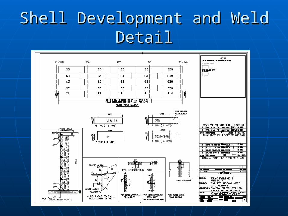
Shell Development and Weld DetailShell Development and Weld Detail
Bottom plate thickness:Bottom plate thickness:
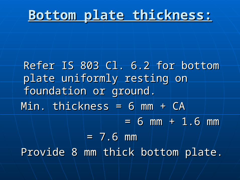
Refer IS 803 Cl. 6.2 for bottom plate Refer IS 803 Cl. 6.2 for bottom plate uniformly resting on foundation or uniformly resting on foundation or ground.ground.
Min. thickness = 6 mm + CAMin. thickness = 6 mm + CA
= 6 mm + 1.6 mm= 6 mm + 1.6 mm
= 7.6 mm= 7.6 mm
Provide 8 mm thick bottom plate.Provide 8 mm thick bottom plate.
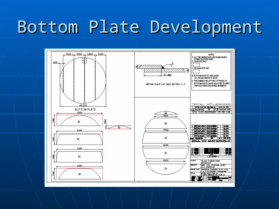
Bottom Plate DevelopmentBottom Plate Development

Self Supporting ConicalSelf Supporting Conical Roof Curb angleRoof Curb angle::
As per IS 803 CI: 6.3.6.2, minimum size of top curb angle As per IS 803 CI: 6.3.6.2, minimum size of top curb angle required is 65 x 65 x 6 mm.required is 65 x 65 x 6 mm.
Provide top curb angle of 75 X 75 X 10 mm all round the Provide top curb angle of 75 X 75 X 10 mm all round the tank.tank.
Area of Curb angle, Ac provided = 14.02 cmArea of Curb angle, Ac provided = 14.02 cm22
Area of Curb angle, Ac required = (PD2/117500 tan G) – Area of Curb angle, Ac required = (PD2/117500 tan G) – 0.1Ws.ts - 0.1Wr.tr0.1Ws.ts - 0.1Wr.tr
Where P is upward pressure on tank roof (allowing for roof Where P is upward pressure on tank roof (allowing for roof self weight) in N/m2.self weight) in N/m2.
Internal Pressure of Tank, Pi = 150 mm WC = 1500 N/m2Internal Pressure of Tank, Pi = 150 mm WC = 1500 N/m2 Weight of Roof Plate = 1130 kgWeight of Roof Plate = 1130 kg Weight of rafter (ISWB 150) with Accessories = 450 kgWeight of rafter (ISWB 150) with Accessories = 450 kg Weight of rafter (ISWB 150) with Accessories = 450 kgWeight of rafter (ISWB 150) with Accessories = 450 kg
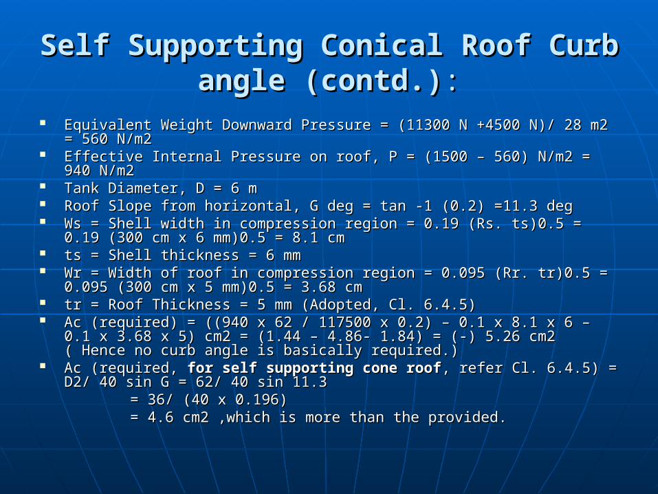
Self Supporting ConicalSelf Supporting Conical Roof Curb angle Roof Curb angle (contd.)(contd.)::
Equivalent Weight Downward Pressure = (11300 N +4500 N)/ 28 m2 = 560 Equivalent Weight Downward Pressure = (11300 N +4500 N)/ 28 m2 = 560 N/m2N/m2
Effective Internal Pressure on roof, P = (1500 – 560) N/m2 = 940 N/m2Effective Internal Pressure on roof, P = (1500 – 560) N/m2 = 940 N/m2 Tank Diameter, D = 6 mTank Diameter, D = 6 m Roof Slope from horizontal, G deg = tan -1 (0.2) =11.3 degRoof Slope from horizontal, G deg = tan -1 (0.2) =11.3 deg Ws = Shell width in compression region = 0.19 (Rs. ts)0.5 = 0.19 (300 cm Ws = Shell width in compression region = 0.19 (Rs. ts)0.5 = 0.19 (300 cm
x 6 mm)0.5 = 8.1 cmx 6 mm)0.5 = 8.1 cm ts = Shell thickness = 6 mmts = Shell thickness = 6 mm Wr = Width of roof in compression region = 0.095 (Rr. tr)0.5 = 0.095 (300 Wr = Width of roof in compression region = 0.095 (Rr. tr)0.5 = 0.095 (300
cm x 5 mm)0.5 = 3.68 cmcm x 5 mm)0.5 = 3.68 cm tr = Roof Thickness = 5 mm (Adopted, Cl. 6.4.5)tr = Roof Thickness = 5 mm (Adopted, Cl. 6.4.5) Ac (required) = ((940 x 62 / 117500 x 0.2) – 0.1 x 8.1 x 6 – 0.1 x 3.68 x 5) Ac (required) = ((940 x 62 / 117500 x 0.2) – 0.1 x 8.1 x 6 – 0.1 x 3.68 x 5)
cm2 = (1.44 – 4.86- 1.84) = (-) 5.26 cm2 ( Hence no curb angle is cm2 = (1.44 – 4.86- 1.84) = (-) 5.26 cm2 ( Hence no curb angle is basically required.)basically required.)
Ac (required, Ac (required, for self supporting cone rooffor self supporting cone roof, refer Cl. 6.4.5) = D2/ 40 sin , refer Cl. 6.4.5) = D2/ 40 sin G = 62/ 40 sin 11.3 G = 62/ 40 sin 11.3
= 36/ (40 x 0.196) = 36/ (40 x 0.196) = 4.6 cm2 ,which is more than the provided.= 4.6 cm2 ,which is more than the provided.
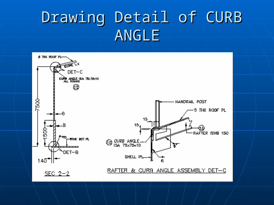
Drawing Detail of CURB ANGLEDrawing Detail of CURB ANGLE
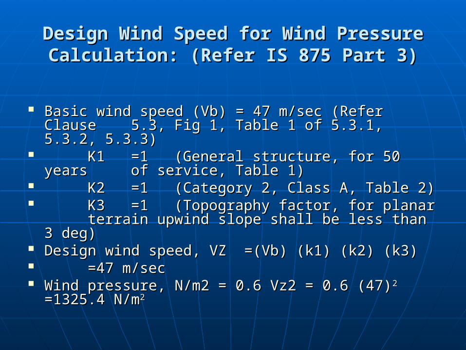
Design Wind Speed for Wind Pressure Design Wind Speed for Wind Pressure Calculation: (Refer IS 875 Part 3)Calculation: (Refer IS 875 Part 3)
Basic wind speed (Vb) = 47 m/sec (Refer Clause Basic wind speed (Vb) = 47 m/sec (Refer Clause 5.3, Fig 1, Table 1 of 5.3.1, 5.3.2, 5.3.3)5.3, Fig 1, Table 1 of 5.3.1, 5.3.2, 5.3.3)
K1K1 =1=1 (General structure, for 50 years (General structure, for 50 years of service, Table 1)of service, Table 1)
K2K2 =1=1 (Category 2, Class A, Table 2)(Category 2, Class A, Table 2) K3K3 =1=1 (Topography factor, for planar (Topography factor, for planar
terrain upwind slope shall be less than 3 deg)terrain upwind slope shall be less than 3 deg) Design wind speed, VZ =(Vb) (k1) (k2) (k3)Design wind speed, VZ =(Vb) (k1) (k2) (k3) =47 m/sec=47 m/sec Wind pressure, N/m2 = 0.6 Vz2 = 0.6 (47)Wind pressure, N/m2 = 0.6 Vz2 = 0.6 (47)22
=1325.4 N/m=1325.4 N/m22
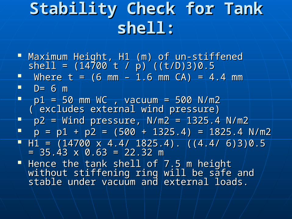
Stability Check for Tank shell:Stability Check for Tank shell:
Maximum Height, H1 (m) of un-stiffened shell = Maximum Height, H1 (m) of un-stiffened shell = (14700 t / p) ((t/D)3)0.5(14700 t / p) ((t/D)3)0.5
Where t = (6 mm – 1.6 mm CA) = 4.4 mmWhere t = (6 mm – 1.6 mm CA) = 4.4 mm D= 6 m D= 6 m p1 = 50 mm WC , vacuum = 500 N/m2 p1 = 50 mm WC , vacuum = 500 N/m2
( excludes external wind pressure) ( excludes external wind pressure) p2 = Wind pressure, N/m2 = 1325.4 N/m2p2 = Wind pressure, N/m2 = 1325.4 N/m2 p = p1 + p2 = (500 + 1325.4) = 1825.4 N/m2 p = p1 + p2 = (500 + 1325.4) = 1825.4 N/m2 H1 = (14700 x 4.4/ 1825.4). ((4.4/ 6)3)0.5 = H1 = (14700 x 4.4/ 1825.4). ((4.4/ 6)3)0.5 =
35.43 x 0.63 = 22.32 m35.43 x 0.63 = 22.32 m Hence the tank shell of 7.5 m height without Hence the tank shell of 7.5 m height without
stiffening ring will be safe and stable under stiffening ring will be safe and stable under vacuum and external loads.vacuum and external loads.
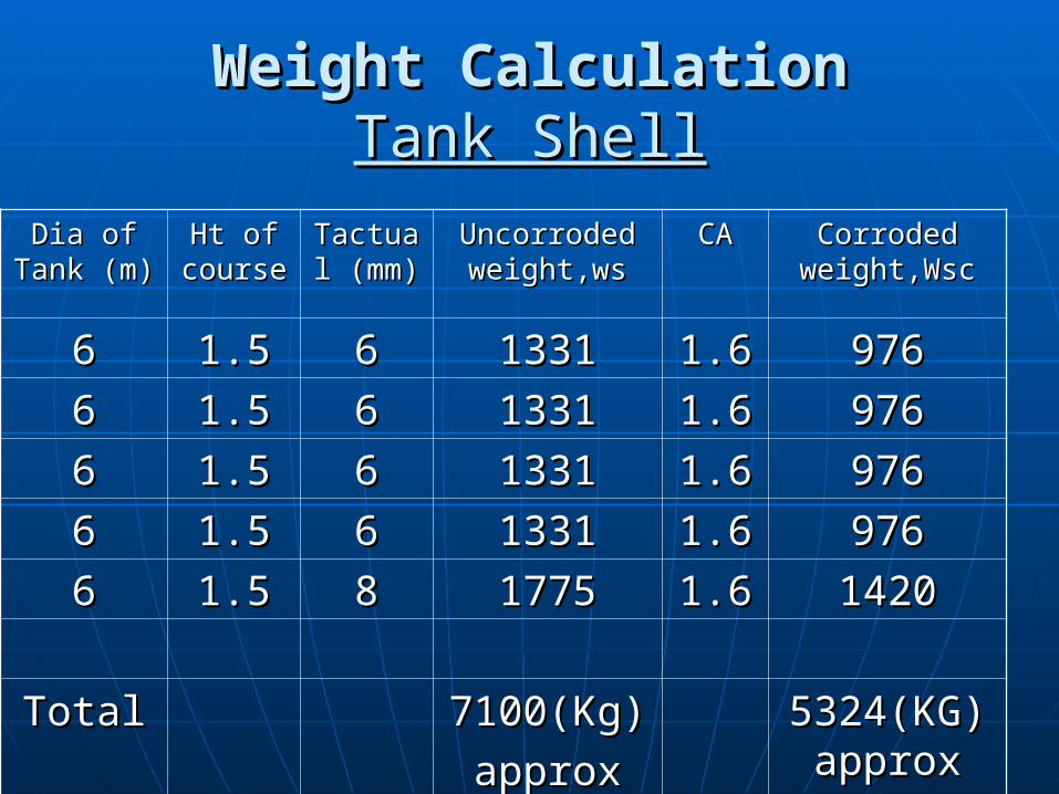
Weight CalculationWeight Calculation Tank ShellTank Shell
Dia of Dia of Tank (m)Tank (m)
Ht of Ht of coursecourse
Tactual Tactual (mm)(mm)
Uncorroded Uncorroded weight,wsweight,ws
CACA Corroded Corroded weight,Wscweight,Wsc
66 1.51.5 66 13311331 1.61.6 976976
66 1.51.5 66 13311331 1.61.6 976976
66 1.51.5 66 13311331 1.61.6 976976
66 1.51.5 66 13311331 1.61.6 976976
66 1.51.5 88 17751775 1.61.6 14201420
TotalTotal 7100(Kg)7100(Kg)
approxapprox5324(KG)5324(KG)approxapprox
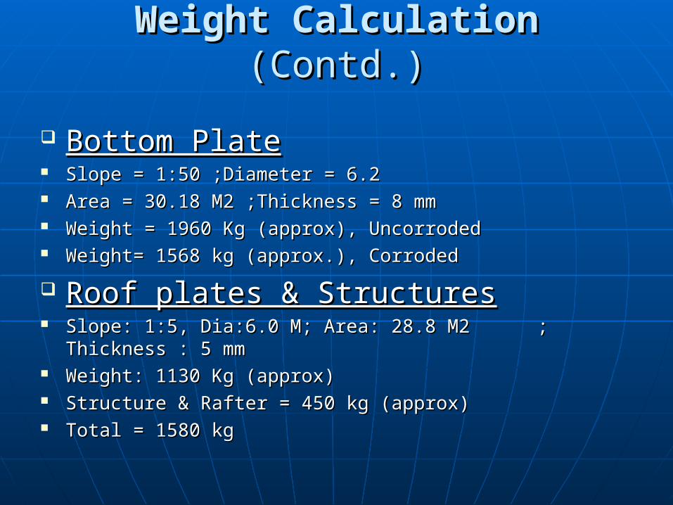
Weight CalculationWeight Calculation (Contd.) (Contd.)
Bottom PlateBottom Plate Slope = 1:50 ;Diameter = 6.2 Slope = 1:50 ;Diameter = 6.2 Area = 30.18 M2 ;Thickness = 8 mmArea = 30.18 M2 ;Thickness = 8 mm Weight = 1960 Kg (approx), UncorrodedWeight = 1960 Kg (approx), Uncorroded Weight= 1568 kg (approx.), CorrodedWeight= 1568 kg (approx.), Corroded
Roof plates & StructuresRoof plates & Structures Slope: 1:5,Slope: 1:5, Dia:6.0 M; Area: 28.8 M2 Dia:6.0 M; Area: 28.8 M2 ; Thickness : 5 ; Thickness : 5
mmmm Weight: 1130 Kg (approx)Weight: 1130 Kg (approx) Structure & Rafter = 450 kg (approx)Structure & Rafter = 450 kg (approx) Total = 1580 kgTotal = 1580 kg
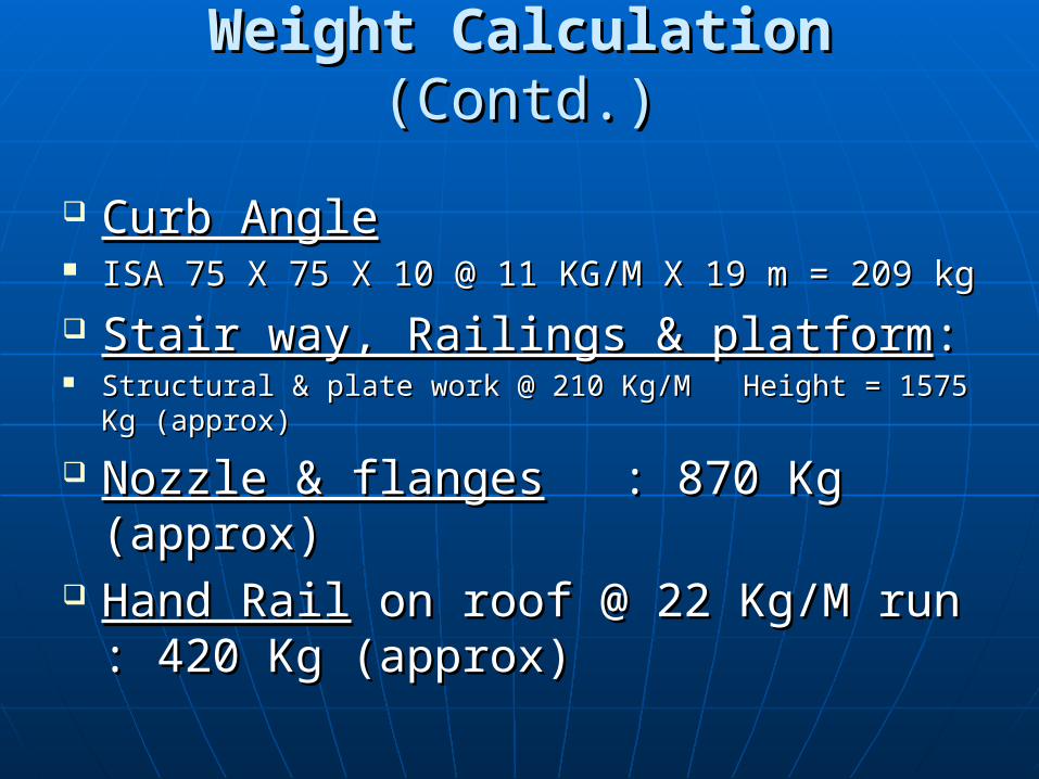
Weight CalculationWeight Calculation (Contd.) (Contd.)
Curb AngleCurb Angle ISA 75 X 75 X 10 @ 11 KG/M X 19 m = 209 kgISA 75 X 75 X 10 @ 11 KG/M X 19 m = 209 kg
Stair way, Railings & platformStair way, Railings & platform:: Structural & plate work @ 210 Kg/M Height = 1575 Kg Structural & plate work @ 210 Kg/M Height = 1575 Kg
(approx)(approx)
Nozzle & flangesNozzle & flanges : 870 Kg (approx): 870 Kg (approx) Hand RailHand Rail on roof @ 22 Kg/M run : on roof @ 22 Kg/M run :
420 Kg (approx)420 Kg (approx)
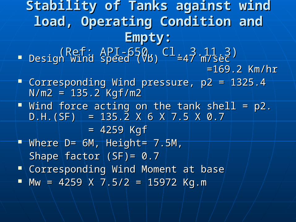
Stability of Tanks against wind load, Stability of Tanks against wind load, Operating Condition and Empty:Operating Condition and Empty:
(Ref: API-650, Cl. 3.11.3)(Ref: API-650, Cl. 3.11.3) Design wind speed (Vb) Design wind speed (Vb) =47 m/sec =47 m/sec
=169.2 Km/hr=169.2 Km/hr Corresponding Wind pressure, p2 = 1325.4 N/m2 Corresponding Wind pressure, p2 = 1325.4 N/m2
= 135.2 Kgf/m2 = 135.2 Kgf/m2 Wind force acting on the tank shell = p2. D.H.(SF)Wind force acting on the tank shell = p2. D.H.(SF)
= 135.2 X 6 X 7.5 X 0.7= 135.2 X 6 X 7.5 X 0.7= 4259 Kgf= 4259 Kgf
Where D= 6M, Height= 7.5M, Where D= 6M, Height= 7.5M, Shape factor (SF)= 0.7Shape factor (SF)= 0.7
Corresponding Wind Moment at baseCorresponding Wind Moment at base Mw = 4259 X 7.5/2 = 15972 Kg.m Mw = 4259 X 7.5/2 = 15972 Kg.m

Roof DevelopmentRoof Development
APPVD.
DATEDRN.CHK'D.
0
N.T.S.
SCALEN K Roy
SACHINMSJ
13-06-07SHEET:
DRAWING NO:
1 OF 1
SUBMISSION FOR APPROVAL13-06-07 SDJ
0
REV.
MSJ
NOTES
CCPL/1084-T2-GGS I SOBHASAN-005
2. The dimensions of the cut pieces of roofplate can be adjusted to meet the site febricationrequirements.
DETAILS OF JOINT NO 3.
DETAILS OF JOINT NO 2.
DETAILS OF JOINT NO 1.
B1
B2
ROOF DEVELOPMENT
1. All the dimensions are in mm unless otherwisespecified.

Stability of Tanks against wind load, Stability of Tanks against wind load, Operating Condition and Empty (Contd.):Operating Condition and Empty (Contd.):
(Ref: API-650, Cl. 3.11.3)(Ref: API-650, Cl. 3.11.3) Weight of the Corroded tank to resist the Moment Weight of the Corroded tank to resist the Moment
(empty condition):(empty condition):
Shell:Shell: 5324 Kg (approx)5324 Kg (approx) Stairway & platform:Stairway & platform: 1575 Kg (approx)1575 Kg (approx) Nozzle:Nozzle: 870 Kg (approx)870 Kg (approx) Roof plate:Roof plate: 1130 Kg (approx)1130 Kg (approx) Roof structure:Roof structure: 450 Kg (approx)450 Kg (approx) Wind girder:Wind girder: - Kg (approx), Not Required- Kg (approx), Not Required Curb girder:Curb girder: 209 Kg (approx)209 Kg (approx) Hand rail on roof:Hand rail on roof: 420 Kg (approx)420 Kg (approx) Bottom Plate:Bottom Plate: 1568 Kg (approx) 1568 Kg (approx) Total:Total: 11546 Kg (approx)11546 Kg (approx)
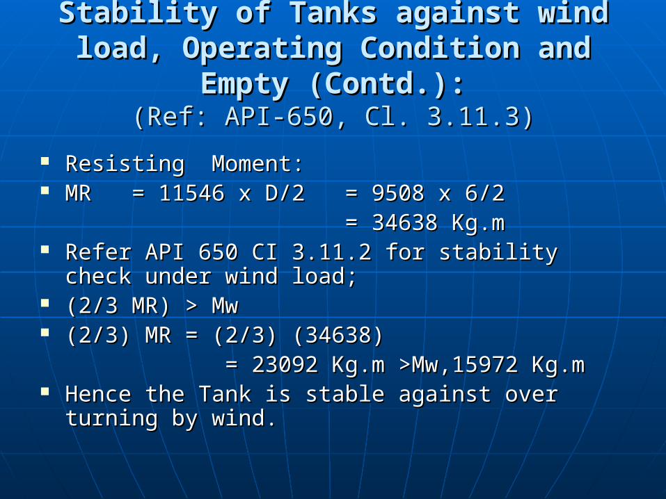
Stability of Tanks against wind load, Stability of Tanks against wind load, Operating Condition and Empty (Contd.):Operating Condition and Empty (Contd.):
(Ref: API-650, Cl. 3.11.3)(Ref: API-650, Cl. 3.11.3)
Resisting Moment:Resisting Moment: MRMR = 11546 x D/2= 11546 x D/2 = 9508 x 6/2 = 9508 x 6/2
= 34638 Kg.m= 34638 Kg.m Refer API 650 CI 3.11.2 for stability check under Refer API 650 CI 3.11.2 for stability check under
wind load;wind load; (2/3 MR) > Mw(2/3 MR) > Mw (2/3) MR = (2/3) (34638)(2/3) MR = (2/3) (34638)
= 23092 Kg.m >Mw,15972 Kg.m= 23092 Kg.m >Mw,15972 Kg.m Hence the Tank is stable against over turning by Hence the Tank is stable against over turning by
wind.wind.
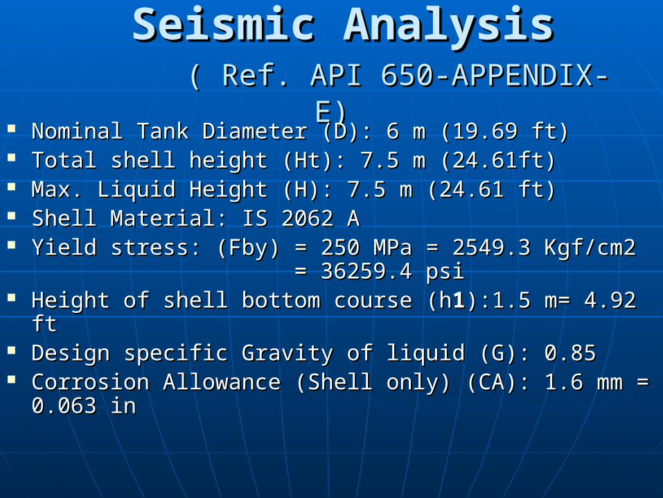
Seismic AnalysisSeismic Analysis ( Ref. API 650-APPENDIX- E)( Ref. API 650-APPENDIX- E)
Nominal Tank Diameter (D): 6 m (19.69 ft)Nominal Tank Diameter (D): 6 m (19.69 ft) Total shell height (Ht): 7.5 m (24.61ft)Total shell height (Ht): 7.5 m (24.61ft) Max. Liquid Height (H): 7.5 m (24.61 ft)Max. Liquid Height (H): 7.5 m (24.61 ft) Shell Material: IS 2062 AShell Material: IS 2062 A Yield stress: (Fby) = 250 MPa = 2549.3 Kgf/cm2 Yield stress: (Fby) = 250 MPa = 2549.3 Kgf/cm2
= 36259.4 psi = 36259.4 psi Height of shell bottom course (hHeight of shell bottom course (h11):1.5 m= 4.92 ft):1.5 m= 4.92 ft Design specific Gravity of liquid (G): 0.85Design specific Gravity of liquid (G): 0.85 Corrosion Allowance (Shell only) (CA): 1.6 mm = 0.063 Corrosion Allowance (Shell only) (CA): 1.6 mm = 0.063
inin
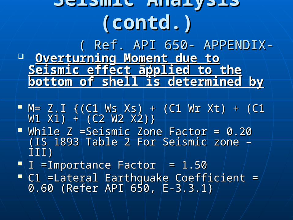
Seismic Analysis (contd.)Seismic Analysis (contd.) ( Ref. API 650- APPENDIX- E)( Ref. API 650- APPENDIX- E)
Overturning Moment due to Overturning Moment due to Seismic effect applied to the Seismic effect applied to the bottom of shell is determined bybottom of shell is determined by
M= Z.I {(C1 Ws Xs) + (C1 Wr Xt) + (C1 W1 M= Z.I {(C1 Ws Xs) + (C1 Wr Xt) + (C1 W1 X1) + (C2 W2 X2)}X1) + (C2 W2 X2)}
While Z =Seismic Zone Factor = 0.20 (IS While Z =Seismic Zone Factor = 0.20 (IS 1893 Table 2 For Seismic zone – III)1893 Table 2 For Seismic zone – III)
I =Importance Factor = 1.50 I =Importance Factor = 1.50 C1 =Lateral Earthquake Coefficient = 0.60 C1 =Lateral Earthquake Coefficient = 0.60
(Refer API 650, E-3.3.1)(Refer API 650, E-3.3.1)
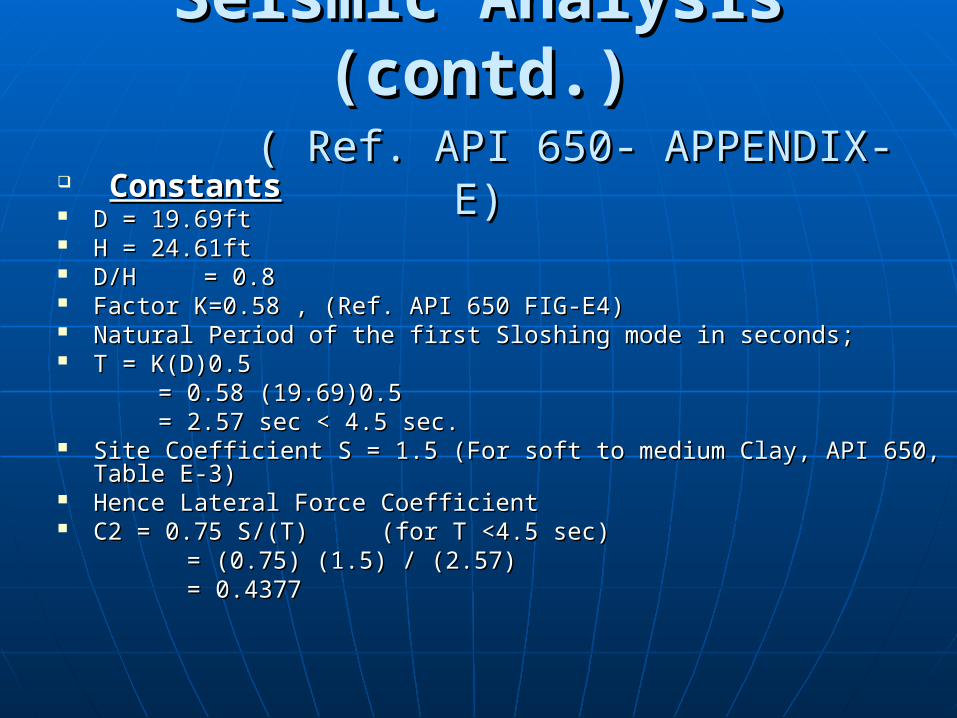
Seismic Analysis (contd.)Seismic Analysis (contd.) ( Ref. API 650- APPENDIX- E)( Ref. API 650- APPENDIX- E)
ConstantsConstants D = 19.69ftD = 19.69ft H = 24.61ftH = 24.61ft D/HD/H = 0.8 = 0.8 Factor K=0.58 , (Ref. API 650 FIG-E4)Factor K=0.58 , (Ref. API 650 FIG-E4) Natural Period of the first Sloshing mode in seconds;Natural Period of the first Sloshing mode in seconds; T = K(D)0.5T = K(D)0.5 = 0.58 (19.69)0.5= 0.58 (19.69)0.5 = 2.57 sec < 4.5 sec.= 2.57 sec < 4.5 sec. Site Coefficient S = 1.5 (For soft to medium Clay, API 650, Table E-3)Site Coefficient S = 1.5 (For soft to medium Clay, API 650, Table E-3) Hence Lateral Force CoefficientHence Lateral Force Coefficient C2 = 0.75 S/(T)C2 = 0.75 S/(T) (for T <4.5 sec)(for T <4.5 sec) = (0.75) (1.5) / (2.57)= (0.75) (1.5) / (2.57) = 0.4377= 0.4377

Seismic Analysis (cont)Seismic Analysis (cont) (Ref. API 650-APPENDIX-E)(Ref. API 650-APPENDIX-E)
WTWT = Total Weight of tank content= Total Weight of tank content= 200 m3 Crude Oil = 200x1000x (0.85)= 170,000 kg= 200 m3 Crude Oil = 200x1000x (0.85)= 170,000 kg= 374786 lbs= 374786 lbs
H H = Max Design liquid level (height)= Max Design liquid level (height) = 24.61 ft = 24.61 ft Refer FIG E 2 – API 650;Refer FIG E 2 – API 650; For D/H value of 0.8, Effective Masses are;For D/H value of 0.8, Effective Masses are; W1/WT= 0.82; W1= 0.82 WT = (0.82) (374786) = 307325 lbsW1/WT= 0.82; W1= 0.82 WT = (0.82) (374786) = 307325 lbs W2/WT= 0.22; W2= 0.22 WT = (0.22) (374786) = 82453 lbsW2/WT= 0.22; W2= 0.22 WT = (0.22) (374786) = 82453 lbs Refer FIG E 3 – API 650;Refer FIG E 3 – API 650; For D/H value of 0.8, Cancroids of seismic forces are;For D/H value of 0.8, Cancroids of seismic forces are; X1/H = 0.42; X1= (H) (0.42) = (24.61) (0.42) = 10.34 ft.X1/H = 0.42; X1= (H) (0.42) = (24.61) (0.42) = 10.34 ft. X2/H = 0.75; X2= (H) (0.75) = (24.61) (0.75) = 18.46 ft.X2/H = 0.75; X2= (H) (0.75) = (24.61) (0.75) = 18.46 ft. Ws Ws = Total weight of Tank shell (un-corroded) = Total weight of Tank shell (un-corroded)
= 7100 kg= 15653 lbs= 7100 kg= 15653 lbs
Seismic Analysis (cont)Seismic Analysis (cont) (Ref. API 650-APPENDIX-E)(Ref. API 650-APPENDIX-E)
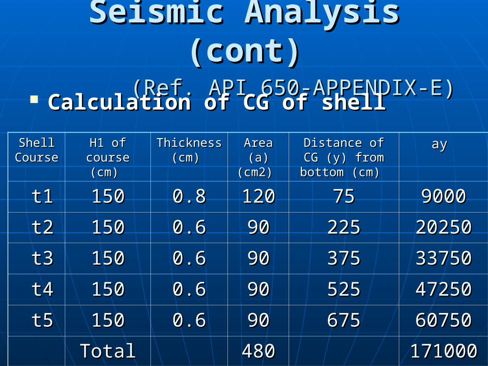
Calculation of CG of shellCalculation of CG of shell
Shell Shell Course Course
H1 of H1 of course (cm) course (cm)
Thickness Thickness (cm) (cm)
Area (a) Area (a) (cm2) (cm2)
Distance of CG Distance of CG (y) from bottom (y) from bottom
(cm) (cm)
ay ay
t1t1 150150 0.80.8 120120 7575 90009000
t2t2 150150 0.60.6 9090 225225 2025020250
t3t3 150150 0.60.6 9090 375375 3375033750
t4t4 150150 0.60.6 9090 525525 4725047250
t5t5 150150 0.60.6 9090 675675 6075060750
TotalTotal 480480 171000171000
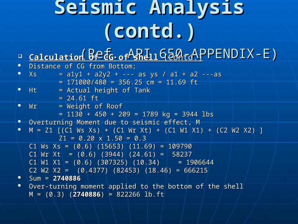
Seismic Analysis (contd.)Seismic Analysis (contd.) (Ref. API 650-APPENDIX-E)(Ref. API 650-APPENDIX-E)
Calculation of CG of shellCalculation of CG of shell (Contd.) (Contd.) Distance of CG from Bottom;Distance of CG from Bottom; XsXs = a1y1 + a2y2 + --- as ys / a1 + a2 ---as= a1y1 + a2y2 + --- as ys / a1 + a2 ---as
= 171000/480 = 356.25 cm = 11.69 ft= 171000/480 = 356.25 cm = 11.69 ft HtHt = Actual height of Tank= Actual height of Tank
= 24.61 ft= 24.61 ft WrWr = Weight of Roof= Weight of Roof
= 1130 + 450 + 209 = 1789 kg = 3944 lbs= 1130 + 450 + 209 = 1789 kg = 3944 lbs Overturning Moment due to seismic effect, MOverturning Moment due to seismic effect, M M = Z1 [(C1 Ws Xs) + (C1 Wr Xt) + (C1 W1 X1) + (C2 W2 X2) ]M = Z1 [(C1 Ws Xs) + (C1 Wr Xt) + (C1 W1 X1) + (C2 W2 X2) ]
Z1 = 0.20 x 1.50 = 0.3Z1 = 0.20 x 1.50 = 0.3C1 Ws Xs = (0.6) (15653) (11.69) = 109790C1 Ws Xs = (0.6) (15653) (11.69) = 109790C1 Wr Xt = (0.6) (3944) (24.61) = 58237C1 Wr Xt = (0.6) (3944) (24.61) = 58237C1 W1 X1 = (0.6) (307325) (10.34)C1 W1 X1 = (0.6) (307325) (10.34) = 1906644= 1906644C2 W2 X2 = (0.4377) (82453) (18.46) = 666215 C2 W2 X2 = (0.4377) (82453) (18.46) = 666215
Sum = Sum = 27408862740886 Over-turning moment applied to the bottom of the shellOver-turning moment applied to the bottom of the shell
M = (0.3) (M = (0.3) (27408862740886) = 822266 lb.ft) = 822266 lb.ft
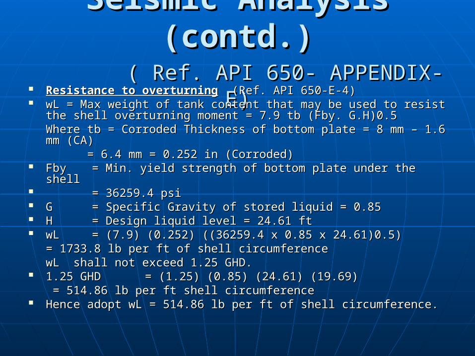
Seismic Analysis (contd.)Seismic Analysis (contd.) ( Ref. API 650- APPENDIX- E)( Ref. API 650- APPENDIX- E)
Resistance to overturningResistance to overturning (Ref. API 650-E-4)(Ref. API 650-E-4) wL = Max weight of tank content that may be used to resist the wL = Max weight of tank content that may be used to resist the
shell overturning moment = 7.9 tb (Fby. G.H)0.5shell overturning moment = 7.9 tb (Fby. G.H)0.5Where tb = Corroded Thickness of bottom plate = 8 mm – 1.6 mm Where tb = Corroded Thickness of bottom plate = 8 mm – 1.6 mm (CA)(CA)
= 6.4 mm = 0.252 in (Corroded)= 6.4 mm = 0.252 in (Corroded) Fby Fby = Min. yield strength of bottom plate under the shell= Min. yield strength of bottom plate under the shell = 36259.4 psi= 36259.4 psi G G = Specific Gravity of stored liquid = 0.85= Specific Gravity of stored liquid = 0.85 H H = Design liquid level = 24.61 ft= Design liquid level = 24.61 ft wL wL = (7.9) (0.252) ((36259.4 x 0.85 x 24.61)0.5)= (7.9) (0.252) ((36259.4 x 0.85 x 24.61)0.5)
= 1733.8 lb per ft of shell circumference = 1733.8 lb per ft of shell circumference wL shall not exceed 1.25 GHD.wL shall not exceed 1.25 GHD.
1.25 GHD1.25 GHD = (1.25) (0.85) (24.61) (19.69) = (1.25) (0.85) (24.61) (19.69) = 514.86 lb per ft shell circumference = 514.86 lb per ft shell circumference
Hence adopt wL = 514.86 lb per ft of shell circumference.Hence adopt wL = 514.86 lb per ft of shell circumference.
Seismic Analysis (contd.)Seismic Analysis (contd.) ( Ref. API 650- APPENDIX- E)( Ref. API 650- APPENDIX- E)
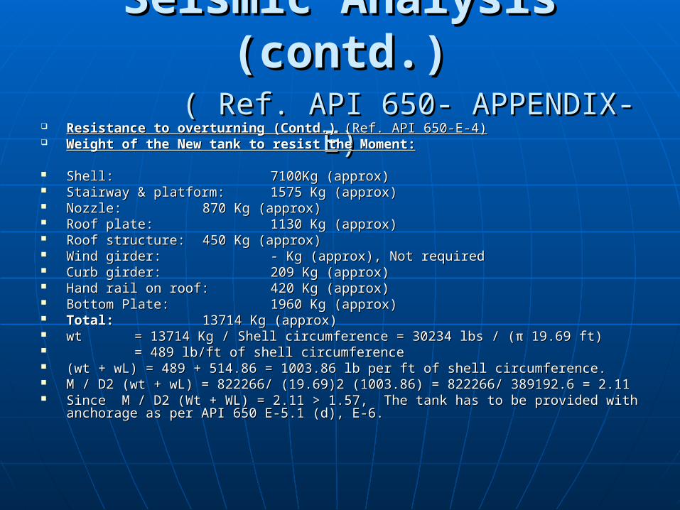
Resistance to overturning (Contd.) Resistance to overturning (Contd.) (Ref. API 650-E-4)(Ref. API 650-E-4) Weight of the New tank to resist the Moment:Weight of the New tank to resist the Moment:
Shell:Shell: 7100Kg (approx)7100Kg (approx) Stairway & platform:Stairway & platform: 1575 Kg (approx)1575 Kg (approx) Nozzle:Nozzle: 870 Kg (approx)870 Kg (approx) Roof plate:Roof plate: 1130 Kg (approx)1130 Kg (approx) Roof structure:Roof structure: 450 Kg (approx)450 Kg (approx) Wind girder:Wind girder: - Kg (approx), Not required- Kg (approx), Not required Curb girder:Curb girder: 209 Kg (approx)209 Kg (approx) Hand rail on roof:Hand rail on roof: 420 Kg (approx) 420 Kg (approx) Bottom Plate:Bottom Plate: 1960 Kg (approx) 1960 Kg (approx) Total:Total: 13714 Kg (approx)13714 Kg (approx) wt wt = 13714 Kg / Shell circumference = 30234 lbs / (π 19.69 ft)= 13714 Kg / Shell circumference = 30234 lbs / (π 19.69 ft) = 489 lb/ft of shell circumference= 489 lb/ft of shell circumference (wt + wL) = 489 + 514.86 = 1003.86 lb per ft of shell circumference.(wt + wL) = 489 + 514.86 = 1003.86 lb per ft of shell circumference. M / D2 (wt + wL) = 822266/ (19.69)2 (1003.86) = 822266/ 389192.6 = 2.11M / D2 (wt + wL) = 822266/ (19.69)2 (1003.86) = 822266/ 389192.6 = 2.11 Since M / D2 (Wt + WL) = 2.11 > 1.57, The tank has to be provided with anchorage Since M / D2 (Wt + WL) = 2.11 > 1.57, The tank has to be provided with anchorage
as per API 650 E-5.1 (d), E-6.as per API 650 E-5.1 (d), E-6.
Seismic Analysis (contd.)Seismic Analysis (contd.) ( Ref. API 650- APPENDIX- E)( Ref. API 650- APPENDIX- E)
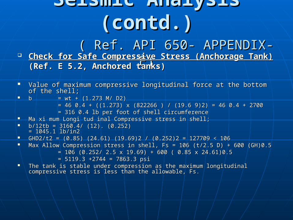
Check for Safe Compressive Stress (Anchorage Tank)Check for Safe Compressive Stress (Anchorage Tank)(Ref. E 5.2, Anchored tanks)(Ref. E 5.2, Anchored tanks)
Value of maximum compressive longitudinal force at the bottom of the Value of maximum compressive longitudinal force at the bottom of the shell;shell;
b b = wt + (1.273 M/ D2)= wt + (1.273 M/ D2)= 46 0.4 + ((1.273) x (822266 ) / (19.6 9)2) = 46 0.4 + 2700= 46 0.4 + ((1.273) x (822266 ) / (19.6 9)2) = 46 0.4 + 2700= 316 0.4 lb per foot of shell circumference= 316 0.4 lb per foot of shell circumference
Ma xi mum Longi tud inal Compressive stress in shell;Ma xi mum Longi tud inal Compressive stress in shell; b/12tb = 3160.4/ (12). (0.252)b/12tb = 3160.4/ (12). (0.252) = 1045.1 = 1045.1
lb/in2lb/in2 GHD2/t2 = (0.85) (24.61) (19.69)2 / (0.252)2 = 127709 < 106GHD2/t2 = (0.85) (24.61) (19.69)2 / (0.252)2 = 127709 < 106 Max Allow Compression stress in shell, Fs = 106 (t/2.5 D) + 600 (GH)0.5Max Allow Compression stress in shell, Fs = 106 (t/2.5 D) + 600 (GH)0.5
= 106 (0.252/ 2.5 x 19.69) + 600 ( 0.85 x 24.61)0.5= 106 (0.252/ 2.5 x 19.69) + 600 ( 0.85 x 24.61)0.5= 5119.3 +2744 = 7863.3 psi= 5119.3 +2744 = 7863.3 psi
The tank is stable under compression as the maximum longitudinal compressive The tank is stable under compression as the maximum longitudinal compressive stress is less than the allowable, Fs.stress is less than the allowable, Fs.
Seismic Analysis (cont)Seismic Analysis (cont) ( Ref. API 650- APPENDIX- E)( Ref. API 650- APPENDIX- E)
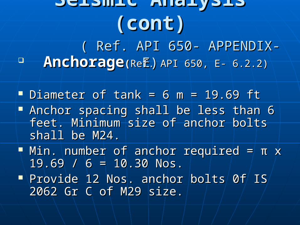
AnchorageAnchorage((Ref. API 650, E- 6.2.2)Ref. API 650, E- 6.2.2)
Diameter of tank = 6 m = 19.69 ftDiameter of tank = 6 m = 19.69 ft Anchor spacing shall be less than 6 feet. Anchor spacing shall be less than 6 feet.
Minimum size of anchor bolts shall be M24.Minimum size of anchor bolts shall be M24. Min. number of anchor required = π x Min. number of anchor required = π x
19.69 / 6 = 10.30 Nos.19.69 / 6 = 10.30 Nos. Provide 12 Nos. anchor bolts 0f IS 2062 Gr Provide 12 Nos. anchor bolts 0f IS 2062 Gr
C of M29 size.C of M29 size.
Recommended