Team 518 i
2021
Jackson Dixon;Ethan Hale;Joseph Ledo-Massey;Max Sirianni;John Storms
FAMU-FSU College of Engineering 2525 Pottsdamer St. Tallahassee, FL. 32310
Team 518: Light-Weight UAV
4/13/2021
Team 518 ii
2021
Abstract
The purpose of our project is to reduce the weight of a drone, resulting in a longer flight
time. Drones provide aerial surveillance and data collection at a fraction of the cost of ordinary
aircraft. They have various applications, both in military and civilian settings. In the military
domain, drones gather intelligence. For civilian use, the farming and agricultural industries use
drones to survey land, count livestock, and check water conditions.
Considering the necessity and function of each part's purpose helped reduce the weight of
the drone. We questioned the job of each part and tried to find other ways to combine them.
Changing a single piece impacts other parts of the drone. Reducing the weight means the drone
needs less power to fly at the same rate as before. Using a lighter battery that provides a more
precise amount of power, results in even more weight savings.
We are applying three weight reducing techniques to the Believer 1960mm aerial
surveying drone. We are reducing the weight of the battery and motors, replacing parts with 3D
printed pieces, and improving the weight of the propellers. Decreasing the weight of the battery
and motors is done by replacing the original parts with lighter versions. The 3D printed pieces
are made of a lightweight filament. Propellers made of carbon fiber are lighter and stronger than
those made of plastic. We aim to have a flight time over one hour. Another part of this project is
developing a tool to measure the effectiveness of the light-weighting techniques used. This tool
can be applied to other projects with weight cutting goals. Looking at the energy consumed by
the drone, after the weight savings, shows the effectiveness of the work performed.
Keywords: UAV, Weight Reduction, Drone, 3D Printing

Team 518 iii
2021
Disclaimer
No disclaimer was needed for this project.

Team 518 iv
2021
Acknowledgement
Team 518 would like to thank our project sponsor, Northrop Grumman, and our point of
contact, Jennifer Tecson, for all of their help. Jennifer provided great insights and helpful
criticism during our project. Without her, we would not have been nearly as successful as we
were. Through our meetings with Jennifer, we also learned what working in industry is like and
how certain tasks are done at Northrop Grumman.
Team 518 would also like to thank Dr. Lance Cooley and Dr. Shayne McConomy for all
of their advice and support during the project. Without them, the project may have taken a
different path, but their guidance helped shape our project and meet our goals.
Team 518 would like to thank the FAMU-FSU College of Engineering and the
Innovation Hub for all of the materials and resources available to us during the building and
testing phase of the project. We were able to validate our methods and create a successful project
utilizing the resources available.

Team 518 v
2021
Table of Contents
Abstract .......................................................................................................................... ii
Disclaimer ..................................................................................................................... iii
Acknowledgement ......................................................................................................... iv
List of Tables................................................................................................................ vii
List of Figures ............................................................................................................. viii
Notation ..........................................................................................................................x
Chapter One: EML 4551C ...............................................................................................1
1.1 Project Scope......................................................................................................1
1.2 Customer Needs .....................................................................................................3
1.3 Functional Decomposition .....................................................................................5
1.4 Target Summary ....................................................................................................8
1.5 Concept Generation ............................................................................................. 11
Concept 1............................................................................................................... 13
Concept 2............................................................................................................... 13
Concept 3............................................................................................................... 13
Concept 4............................................................................................................... 13
Concept 5............................................................................................................... 14
Concept 6............................................................................................................... 14
Team 518 vi
2021
Concept 7............................................................................................................... 14
Concept 8............................................................................................................... 14
1.6 Concept Selection ................................................................................................ 14
1.8 Spring Project Plan .............................................................................................. 26
Chapter Two: EML 4552C ............................................................................................ 27
2.1 Restated Project Definition and Scope.................................................................. 27
2.2 Results & Discussion ........................................................................................... 29
2.3 Conclusion ........................................................................................................... 42
2.4 Future Work......................................................................................................... 44
2.5 References ........................................................................................................... 45
Appendices .................................................................................................................... 46
Appendix A: Code of Conduct ....................................................................................... 47
Appendix B: Functional Decomposition ........................................................................ 51
Appendix C: Target Catalog .......................................................................................... 53
Appendix D: Operation Manual ..................................................................................... 54
Appendix E: Engineering Drawings ............................................................................... 70
Appendix F: Risk Assessment ....................................................................................... 77
Team 518 vii
2021
List of Tables
Table 1 Customer Needs ..................................................................................................3
Table 2 Critical Targets and Metrics ...............................................................................9
Table 3 House of Quality ............................................................................................... 16
Table 4 Pugh Chart Iteration One ................................................................................. 18
Table 5 Pugh Chart Iteration 2 ...................................................................................... 19
Table 6 Pugh Chart Iteration Three ............................................................................... 20
Table 7 Matrix Criteria.................................................................................................. 21
Table 8 Matrix Criteria Weight ...................................................................................... 22
Table 9 Criteria Consistency Check ............................................................................... 23
Table 10 Criteria Bias Check ......................................................................................... 24
Table 11 Final Rating Matrix ........................................................................................ 24
Table 12 Alternative Weight of Concepts ....................................................................... 25
Table 13 Propeller Characteristics ................................................................................ 32
Table 14 Original Thrust Data from Manufacturer ........................................................ 34
Table 15 Thrust Data from Original Motor Test ............................................................ 34
Table 16 Thrust Data from New Motor Test ................................................................... 35
Table 17 Future energy Savings ..................................................................................... 41
Table 18 Major Functions Cross Reference Table ......................................................... 51
Table 19 Major Functions and Subfunctions Cross Reference Table .............................. 51
Table 20 Targets and Metrics for UAV Functions .......................................................... 53
Table 21 3D Printer Settings ......................................................................................... 63

Team 518 viii
2021
List of Figures
Figure 1 Functional Decomposition .................................................................................6
Figure 2 Spring Project Plan ......................................................................................... 26
Figure 3 Believer 1960................................................................................................... 29
Figure 4 Turnigy and Lumenier Batteries ....................................................................... 30
Figure 5 iFlight XING x2814 880kv Motor..................................................................... 31
Figure 6 Quanum Carbon Fiber Propellers ................................................................... 33
Figure 7 Wing Connecting Parts .................................................................................... 36
Figure 8 Creo Model of Wing Connecting Parts............................................................. 36
Figure 9 LW-PLA Strength Test ..................................................................................... 37
Figure 10 Final Design of Wing/Empennage Connecting Pieces .................................... 37
Figure 11 Forces Acting on UAV ................................................................................... 38
Figure 12 Highway Fuel Economy Test Velocity Profile ................................................ 39
Figure 13 Modified Velocity Profile ............................................................................... 40
Figure 14 Energy Consumption of the UAV ................................................................... 41
Figure 15 Complete Assembly of the Believer- Front ..................................................... 43
Figure 16 Complete Assembly of the Believer- Rear ....................................................... 44
Figure 17 Wiring Diagram 1 .......................................................................................... 57
Figure 18 Power Control Board Wiring ......................................................................... 58
Figure 19 Flight Controller Wiring ................................................................................ 59
Figure 20 Power Leads .................................................................................................. 60

Team 518 ix
2021
Figure 21 Battery Eliminator Circuit ............................................................................. 61
Figure 22 Regulating Cover ........................................................................................... 62
Figure 23 Latching Hook ............................................................................................... 62
Figure 24 Wing Connecting Part Design ........................................................................ 62
Figure 25 GPS Module/Safety Switch ............................................................................ 66
Figure 26: Believer 1960 Top View ................................................................................ 67
Figure 27: Believer 1960 Side View ............................................................................... 68
Figure 28: Servo Motor Installing Base Top ................................................................... 70
Figure 29: Servo Motor Installing Base.......................................................................... 71
Figure 30: Latching Hook (Female) ............................................................................... 72
Figure 31: Empennage Connecting Part (male) ............................................................. 72
Figure 32: Empennage Connecting Part (female) ........................................................... 73
Figure 33: Wing Connecting Part (male) ....................................................................... 73
Figure 34: Latching Hook (male) ................................................................................... 74
Figure 35: Motor Installing Base ................................................................................... 75
Figure 36: Wing Connecting Part (female) ..................................................................... 75
Figure 37: Rear Empennage Connecter ......................................................................... 76

Team 518 x
2021
Notation
UAV Unmanned Aerial Vehicle
FL Force of Lift
FD Force of Drag
T Thrust
FG Force of Gravity
m Mass
a Acceleration
g Acceleration due to Gravity
V Velocity
E Energy
A Area
PLA Polylactic Acid
LW-PLA Light Weight Polylactic Acid
�̇� Mass Flow Rate
ρ Density
CL Coefficient of Lift
CD Coefficient of Drag

Team 518 1
2021
Chapter One: EML 4551C
1.1 Project Scope
Project Description:
The objective of this project is to develop a lightweight UAV to directly increase
the flight time while maintaining surveillance capabilities. Multiple light-weighting processes
will be used to complete this task.
Key Goals:
The key goals of this project are what the team aims to accomplish by the end of
the project:
• Increase the flight time of the UAV.
• Keep the UAV lightweight compared to market ready UAV’s.
• Develop the UAV with multiple light-weighting techniques.
• The UAV can be easily transported and operated.
• The UAV will have quality surveillance recordings.
Markets:
The markets for this project are those that the lightweight UAV can be used in. These
markets include primary and secondary markets. The lightweight UAV is mainly designed to be
used in the primary markets, but the members of the secondary markets also have an interest in
the product. The primary market of this project are farmers and members of the agricultural
community. Secondary markets for this project include the US Military, infrastructure
companies, hobbyists, land surveyors, and teaching facilities.
Team 518 2
2021
Assumptions:
• The UAV will be operated in Earth’s atmosphere.
• The flight conditions are typical of the climates in the United States.
• The UAV is remotely controlled.
• The UAV is category 1, as defined by the DoD.
o A category 1 UAV has a maximum gross takeoff weight within 0-20lbs, normal
operating altitude less than 1,200ft AGL (above ground level), and an airspeed
less than 100 knots.
• The UAV will be flown in clear airspace.
• The UAV will follow all state and federal laws.
Stakeholders:
The stake holders for this project are those that are directly influenced by the work done
to develop the lightweight UAV. These parties have invested resources or control of the outcome
of the lightweight UAV. For this project, the stakeholders are:
• Northrop Grumman
• Dr. Shayne McConomy
• Dr. Lance Cooley
• Senior Design Team 518
Team 518 3
2021
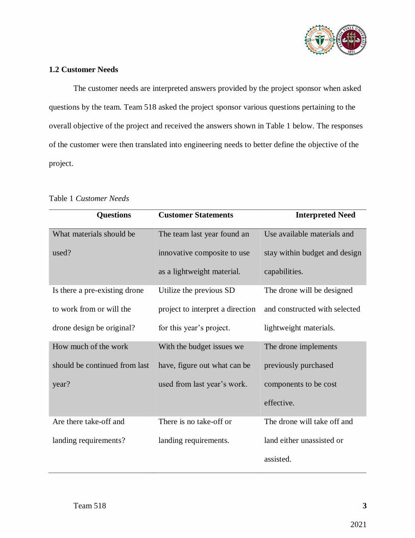
1.2 Customer Needs
The customer needs are interpreted answers provided by the project sponsor when asked
questions by the team. Team 518 asked the project sponsor various questions pertaining to the
overall objective of the project and received the answers shown in Table 1 below. The responses
of the customer were then translated into engineering needs to better define the objective of the
project.
Table 1 Customer Needs
Questions Customer Statements Interpreted Need
What materials should be
used?
The team last year found an
innovative composite to use
as a lightweight material.
Use available materials and
stay within budget and design
capabilities.
Is there a pre-existing drone
to work from or will the
drone design be original?
Utilize the previous SD
project to interpret a direction
for this year’s project.
The drone will be designed
and constructed with selected
lightweight materials.
How much of the work
should be continued from last
year?
With the budget issues we
have, figure out what can be
used from last year’s work.
The drone implements
previously purchased
components to be cost
effective.
Are there take-off and
landing requirements?
There is no take-off or
landing requirements.
The drone will take off and
land either unassisted or
assisted.
Team 518 4
2021
Quadcopter or fixed wing
drone?
Look at the work of last year.
A quad rotor is harder to
control.
The UAV will be of the fixed
wing style.
What kind of payload is
expected to be a part of the
UAV?
Payload can be for
surveillance or data collection
purposes.
The UAV will have a
payload.
Can the components be
outsourced, or will the
components need to be self-
created?
Decide a payload size/range.
Unnecessary to create
sensors.
The drone will use
outsourced components.
What is the size requirement
for the UAV?
Look at existing design from
last year.
The drone is smaller than
double the reference drone.
What is the weight restriction
of the UAV?
Look at the work of last year
but light-weighting can come
in forms of efficiency.
The drone will be a category
1 UAV.
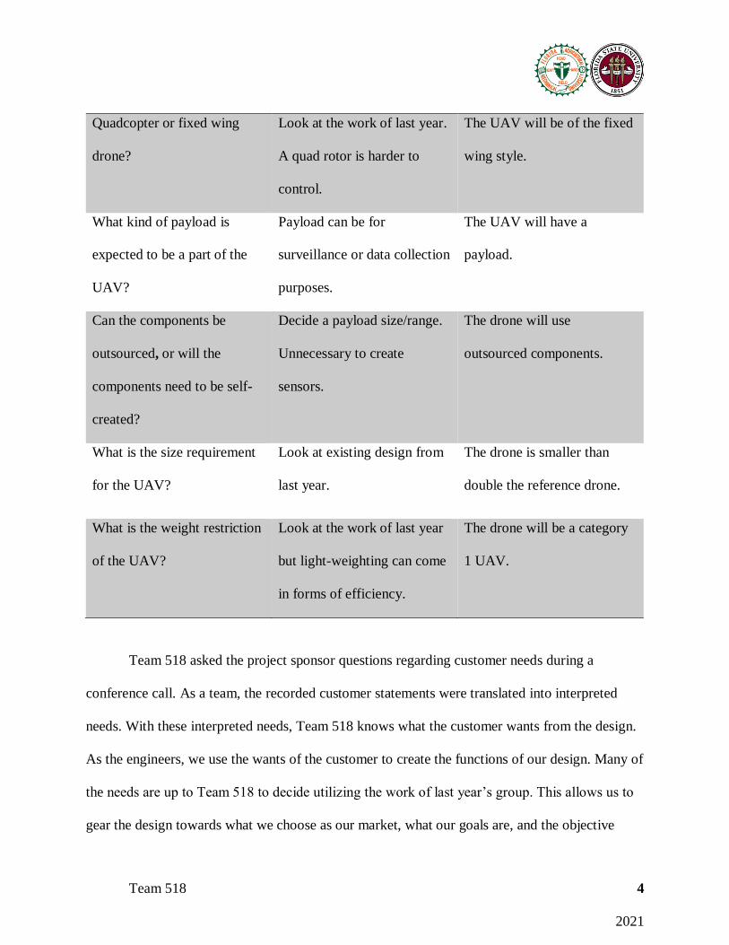
Team 518 asked the project sponsor questions regarding customer needs during a
conference call. As a team, the recorded customer statements were translated into interpreted
needs. With these interpreted needs, Team 518 knows what the customer wants from the design.
As the engineers, we use the wants of the customer to create the functions of our design. Many of
the needs are up to Team 518 to decide utilizing the work of last year’s group. This allows us to
gear the design towards what we choose as our market, what our goals are, and the objective
Team 518 5
2021
created. One area that will have future implications on our design is the unestablished budget.
Team 518 will be developing a lightweight UAV with the purpose of increasing the flight time
and having an incorporated payload.
1.3 Functional Decomposition
The functional decomposition allows the overall project system to be broken down into
smaller functions and subsystems. The functional decomposition portrays the actions the
project’s systems must fulfill. Figure 1, below, is the functional decomposition for the
lightweight UAV of this project. This functional decomposition was developed through
discussions with the project sponsor, Northrop Grumman, and by referencing the work of the
previous group.

Team 518 6
2021
Figure 1 Functional Decomposition
The five main functions of the lightweight UAV are communication, flight, power,
surveillance, and structure. As a team, we discussed what was necessary to make the UAV fly
properly and perform proper surveillance. Each one of these major functions is broken down into
subfunctions. The subfunctions are what is needed for the major functions to perform properly.
For the communication function to succeed, the UAV must receive commands from the user as
well as send video feed back to the user. Another aspect of the communication function is that
the UAV must provide feedback about its flight status to the user. For the flight function to
succeed, the UAV must accelerate, decelerate, and adjust roll, pitch, and yaw. These are the
dynamics that go into making a plane, or in this case a UAV, fly. The power function succeeds
when there is power to the flight control and payload subsystems. Without power to the flight

Team 518 7
2021
controls (motors, actuators, receivers) the plane won’t move. Also, there must be power to the
payload for the payload to function correctly. The surveillance function needs to record video as
well as orient the payload in a direction to be successful and complete the project objective of
providing surveillance. The structure function is needed to support the weight of the UAV,
generate lift to get the UAV off the ground, store all the hardware involved in making the UAV
work, and allow the payload to attach to the UAV. All these functions and sub-functions are
what allows the lightweight UAV to perform and meet the project objective.
Priorities of Main Functions:
Structure- This function is placed in first because the craft must be able to support itself
in flight as well as during takeoff and landing. If the UAV doesn’t support its own weight, and
the structural system fails, there will be no UAV to fly. Looking at table 2, all the other functions
rely on the structure function.
Power- The power function is ranked second on or list of functions. Without adequate
power the UAV is unable to move, and unable to achieve flight. Also, the power is necessary for
the communication and surveillance functions to work. Power is critical because it supports the
other main systems throughout the UAV.
Flight- Flight is necessary to get airborne. Due to the UAV’s default flight setting, it is
neither dependent on communication nor surveillance. If the drone is unable to fly, the Team’s
mission will fail, no matter how well the rest of the UAV is designed.
Communication- The communication function ranks fourth in our priorities list. The
communication function relies on the power system because it needs power before it can work.
The drone relies on the communication between the user and flight controller on the UAV in

Team 518 8
2021
order to relay how the drone needs to maneuver during flight. Also, the drone will need to be
flying before it can communicate the desired feedback data to the user.
Surveillance- Surveillance is the last function to receive priority because it is dependent
on all the other functions being accomplished. The first objective of this project is to achieve an
increased flight time using light-weighting techniques, then provide surveillance. The drone can
still fly without the surveillance aspect working.
1.4 Target Summary
Targets and metrics are used to establish the certain values the functions and needs of the
design must meet. These define the goals the product will be compared to in order to validate the
work done to create the project. Each function has a metric, what is used to validate the function,
as well as a target, the specific value of the metric. Metrics are the length used to measure an
object, determining the volume of container, or using a thermometer to measure the temperature.
The targets that match these measuring techniques would be establishing the length as 12 inches,
calculating the volume to be 3 cubic-meters, or saying the temperature is 100° Fahrenheit. For
our project, we developed targets and metrics for each function. These can be seen in Appendix
B. These targets and metrics were developed using data on the Believer 1960 mapping UAV,
further research on UAVs, and basic physics concepts. The technical data for the Believer 1960
was used to generate most of the targets in the overall targets and metrics table in Appendix B.
However, the data listed for the Believer 1960 was very limited. We had to manipulate the data
to create certain targets to match the metrics. Since our primary market is the farming and
agricultural industry, we used data based on farm sizes in Florida to acquire some targets.

Team 518 9
2021
In order to test and validate our product and to establish whether our targets were met,
many tools will be used. The biggest tool will be a computer and software we can acquire. We
will use the computer to manipulate designs, change the material the design is constructed of,
and validate targets for functions like the support function. This tool allows us to analyze stress
points in our designs too. Another tool we will have to use is a stopwatch. This may be used to
time the running endurance of components like battery and motors under certain loads. A third
tool we may need to validate our design is a multimeter. A multimeter will be used to analyze
currents drawn by electric components as well as voltage differences in the electrical system.
In order to help further define the project objective, certain targets and metrics were
chosen as critical. These critical targets and metrics are essential for the customer needs to be
met as well as the project objective. Table 4. below highlights these critical targets and metrics.
Table 2 Critical Targets and Metrics
Functions Metrics Targets
Bolster Weight Support moment due to wing 1.128N/m
Generate Lift
Airfoil produces greater lift
force than gross weight
54 Newtons
Couple Payload Mass of Payload supported 600g
Endurance Overall Flight Time 60 mins
Bolstering the weight is considered a critical target because for the UAV to fly correctly
it needs to be able to support all the components inside the UAV. Without the UAV being able to
hold the wings, battery, electrical components, and other hardware, the UAV will not be
Team 518 10
2021
structurally sound. This will ultimately lead to us not hitting our objective. Supporting the wings
is the weight that is mainly hanging off the plane. The moment calculated due to the wing,
assumed that the weight was all the way at the tip of one wing. One wing’s weight is .11736kg
and has a length of 980mm. Converting .11736kg to 1.1513 newtons and converting 980mm to
.98m. The moment was taken just by multiplying 1.1513 by .98m to get 1.128N/m.
Generating lift is a critical element of any flying vehicle. The target of greater or equal to
54 Newtons for lift was determined by calculating the required lift the UAV must generate in
order to achieve flight (Believer 1960mm, n.d.). To takeoff the lifting force must be greater than
the weight of the UAV and to maintain altitude above the ground the lifting force must be equal
to weight of the UAV. To test our target for generating lift the profile of the UAV along with the
estimated airspeed of the UAV will be used to calculate the aerodynamic properties of the UAV
to include lift.
By enabling the drone to transport a camera or some other device, it transforms from a
cool toy to a highly valuable piece of equipment for many industries. The target of 600g was
obtained by researching cameras designed to be used in small drones (UAV Cameras, n.d.). This
mass range satisfies the need to compromise high quality camera capabilities and light weight
with the price of the camera. Many cameras that fall within this mass range can take quality
video footage and will not overload the drone. They also satisfy our budget by not being the most
expensive. By constraining within these three specifications, we will be able to choose the
appropriate camera to aid our overall goal. To test the UAV’s ability to carry the payload,
analyses on the affects the payload has on the center of gravity will be performed. If the payload
moves the center of gravity too much, causing instability in the UAV, then a different payload

Team 518 11
2021
will need to be selected. These calculations can be performed by formulating simple moment
equations.
The primary driving force behind the objective of light-weighting a UAV is to increase
the flight time. This is not a function of our system but is critical to meeting our objective. The
metric that will be used to validate the flight time, or endurance, of the UAV will be time. The
target that is paired with this metric is to increase the flight time to be greater than or equal to 60
mins. Flight time is a quality of a UAV that is influenced by many factors, the speed the UAV is
operated at, the battery charge, etc. To obtain this target, we investigated the listed flight times of
multiple drones. The typical flight time of a Quadrotor drone is shy of 30 minutes (Wales, 2020).
Some advanced fixed wing mapping drones can operate in the air for over an hour, nearly 90
minutes (Why Fly A Fixed-Wing Drone, 2019). So, having the endurance of our UAV being at
least 60 minutes will allow our UAV to outperform quadrotor drones that are extremely popular
and be competitive with other fixed wing drones. To validate whether this target is met, tests will
be performed to investigate the battery life while electrical components of the UAV are run.
Once a physical prototype is developed, timing the actual flight time of the UAV in the air can
also be used to validate this target. If the UAV operates for 1 hour or longer, the UAV has met its
endurance target. If this target is not met, design changes will be made to the UAV to ensure it is
met while maintaining the lightweight project objective.
1.5 Concept Generation
In order to develop the best product and meet our objective, the team underwent a
concept generation session. In this session, multiple concept generation techniques were used.
Team 518 12
2021
Our goal is to lightweight the Believer 1960mm, a commercially available mapping UAV, and
through brainstorming and other methods, we developed concepts to successfully do so.
To develop many of the concepts, the team took a biomimicry approach to
brainstorming. This is when you think of your project in a way that relates to nature. What in
nature represents aspects or a solution to your problem? For us, we looked at birds. Some birds
can fly long periods of time since they have large wingspans that generate lift as they glide in the
air. However, in general, birds have very light weight bones. If we can develop a structure
similar to the bone structure of birds, that would help us reach our objective greatly.
Another approach we took to develop concepts was the anti-problem approach. This style
of brainstorming is when the team thinks of the opposite of the problem. For us, that would be
looking at making the UAV heavier. What can we do to make the UAV heavier? Well, a big
heavy aspect of the UAV is the battery and electrical system. So, from there, we reverse the
question and focus back to our goal of light weighting. We can develop a lighter UAV by
reducing the weight of the battery and electrical system.
A third approach Team 518 took to generate concepts was to take an approach similar to
a morphological chart. We took our systems and analyzed the current components that exist in
the UAV. We have an electrical system, made of batteries, controllers, and receivers. We have a
flight system, made of motors to drive the plane through the air and control the ailerons. We
have a support system that holds the plane together. And we have a payload system made of a
camera to capture the necessary data. Analyzing these subsystems individually, we can look at
how to light weight each one and then combine these to get an overall reduction in weight. One
example of light weighting the flight system is by improving the propellor design. Also,
Team 518 13
2021
analyzing the support structure, using a more efficient rib structure may allow us to reduce the
weight of the supports while maintaining the needed strength.
After brainstorming, we had 100 concepts listed. As a team, we were able to narrow these
down to a total of eight concepts. Five of these concepts are medium fidelity concepts and three
of them are high fidelity concepts. The medium fidelity concepts are listed in the table below:
Concept 1.
Regenerative Power Source: Utilizing a battery that charges as the device flies can
eliminate the need for a large battery. This may extend the flight time and light weight the UAV
Concept 2.
Generative Design: Utilizing generative design programs in CAD programs we can create
optimally designed parts for the UAV. Generative design eliminate waste material by taking in
parameters set by the designer. It would reduce the weight of parts but retain the structural
qualities.
Concept 3.
Honeycomb Structures: Using honeycomb shaped structures can help reduce the weight
of solid parts. By making parts hollow and keeping rigidity, the UAV would be lighter but retain
the needed structural qualities.
Concept 4.
Electrical Components Used as Support: This concept implies that the wiring of the
electrical system would also have a structural purpose. By having a single component serve two
purposes, the needed strength of other components is less, and the weight of the UAV is reduced.

Team 518 14
2021
Concept 5.
Complete Wing Design: This idea assumes that redesigning the fuselage and wings of the
UAV to resemble the B-2 Stealth Bomber can help reduce the weight of the UAV. By
eliminating the long fuselage, the weight can be reduced, and the entire body of the UAV now
creates lift, instead of the wings and tail alone.
Concept 6.
LW-PLA Constructed Parts: Recreating parts of the UAV using additive manufacturing
can help reduce the weight of the UAV. LW-PLA is a new 3D printing filament that expands
when printing at certain temperatures making it extremely lightweight.
Concept 7.
Lighter Electrical Components: The electrical components of the UAV are the heaviest
parts. Implementing smaller batteries and motors will help light-weight the UAV. If the weight is
reduced, the UAV won’t need as much power and a smaller battery will be needed.
Concept 8.
Improve Propeller Construction: Propellers made of a lighter material save weight from
the overall UAV. Also, with less rotating mass, the lighter propellers don’t need as much energy
to turn and help meet the project objective.
1.6 Concept Selection
Once the concepts were generated, the next step was to select the best concept to meet
our objective. To do so, the team narrowed down the medium fidelity concepts, based on
feasibility and predicted best results, to just two. These were then combined with the three high
fidelity concepts to be analyzed and selected as the best concept. The analysis techniques used to

Team 518 15
2021
select the best concept were a House of Quality, iterations of Pugh charts, and an Analytical
Hierarchy Process (AHP) examination. Each of these analysis techniques analyzes how well the
concepts meet the project objective. The end goal is to use these techniques to find the concept
that best accomplishes the project objective.

Team 518 16
2021
Table 3 House of Quality
House of Quality Engineering Characteristics
Improve Direction
Units Kg Sec m m g N n/a m/s m m deg
Customer Requirements
Import
ance
Wei
ght
Fac
tor
Over
all
Wei
ght
Endura
nce
Win
gsp
an
Len
gth
Pay
load
Wei
ght
Win
g r
igid
ity
Mat
eria
l D
ura
bil
ity
Vel
oci
ty C
ontr
ol
Alt
itud
e
Sig
nal
Ran
ge
Pay
load
Co
ntr
ol
UAV constructed of
lightweight materials 7 9 7 5 7 7 7 3 3 1 1
UAV implements
previously purchased
components
3 1 5 1 3
UAV takes off and
lands assisted or
unassisted
1 3 5 7 1
The UAV is of the fixed
wing style 3 3 9 9 1 9 3 5 3
The UAV has a payload 6 5 5 3 9 1 5 1 1 7
The UAV uses
outsourced components 1 9 3 3
The UAV is smaller
than double the
reference drone
3 7 1 3 1 1 1
The UAV is category 1 4 7 7 3 9
Raw Score 905 154 109 71 73 106 85 54 82 79 22 70
Relative Weight % 17.02 12.04 7.85 8.07 11.71 9.39 5.97 9.06 8.73 2.43 7.73
Rank Order 1 2 8 7 3 4 10 5 6 11 9
Team 518 17
2021
The purpose of the House of Quality is to determine the top engineering characteristic by
comparing them to customer requirements. The House of Quality contains 11 engineering
characteristics as well as customer requirements. These customer requirements were given
importance factors based on the binary pairwise comparison table found in appendix D. The 11
engineering characteristics were individually compared to each customer requirement and given
a score depending on how much that customer requirement affects each engineering
characteristic. The scoring system has 1 being the lowest score and 9 being the highest possible
score for each engineering characteristic. We chose the top five engineering characteristics to
move forward with in the concept analysis because they best define the project objective. After
each individual score was marked down, the scores for the columns were determined by taking
the individual score, multiplying it by the importance factor, and finally summing it all up at the
end. From our House of Quality our engineering characteristics were ranked in order of
importance as follows: overall weight, endurance, payload weight, wing rigidity, and velocity
control.
The Pugh Charts below were used to identify the concepts that would be most beneficial
in helping us achieve our goal of light weighting a UAV. Pugh Charts compare multiple concept
ideas to a known datum based on criteria in the left most column. The criteria consist of the
engineering characteristics that were ranked in the House of Quality. A concept is rated (+) if it
would meet a criterion better than the datum could. A (-) if the concept would not do better, and
an S if it would produce about the same result. The concept with the worst score is eliminated as
a viable idea.
Team 518 18
2021
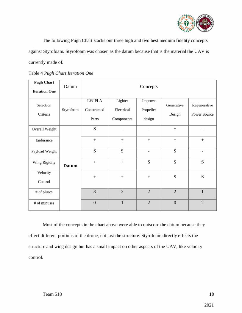
The following Pugh Chart stacks our three high and two best medium fidelity concepts
against Styrofoam. Styrofoam was chosen as the datum because that is the material the UAV is
currently made of.
Table 4 Pugh Chart Iteration One
Pugh Chart
Iteration One
Datum Concepts
Selection
Criteria
Styrofoam
LW-PLA
Constructed
Parts
Lighter
Electrical
Components
Improve
Propeller
design
Generative
Design
Regenerative
Power Source
Overall Weight
Datum
S - - + -
Endurance + + + + +
Payload Weight S S - S -
Wing Rigidity + + S S S
Velocity
Control
+ + + S S
# of pluses 3 3 2 2 1
# of minuses 0 1 2 0 2
Most of the concepts in the chart above were able to outscore the datum because they
effect different portions of the drone, not just the structure. Styrofoam directly effects the
structure and wing design but has a small impact on other aspects of the UAV, like velocity
control.

Team 518 19
2021
Another Pugh Chart was made using the “Improve Propeller Design” concept as the
datum. This datum was chosen because in comparison to Styrofoam, in the chart above, it did not
create any noticeable change.
Table 5 Pugh Chart Iteration 2
Pugh Chart
Iteration Two
Datum Concepts
Selection
Criteria
Improve Propeller
Design
LW-PLA
constructed
parts
Lighter Electrical
Components
Generative
Design
Regenerative
Power Source
Overall Weight
Datum
- - + -
Endurance + S + +
Payload Weight S S S -
Wing Rigidity + S S S
Velocity
Control
- + S -
# of pluses 2 1 2 1
# of minuses 2 1 0 3
The results of this Pugh Chart reveal that once again “Regenerative Power Source” will
not be the best concept to apply to reach our end goal. It also shows that the “Generative Design”
concept will aid our project or, at the very least, it will not hinder it. With the results of this chart,
the “Regenerative Power Source” concept can be eliminated as a possible technic for light
weighting the UAV.

Team 518 20
2021
The last Pugh Chart consists of the remaining concepts, with the “Lighter Electrical
Components” concept being used as the datum. By comparing our concepts to each other in this
manner, it can be determined which concepts are best to pursue further based on side-by-side
comparison.
Table 6 Pugh Chart Iteration Three
Pugh Chart
Iteration Three
Datum Concepts
Selection Criteria
Lighter Electrical
Components
LW-PLA
Constructed Parts
Improve Propeller
Design
Generative Design
Overall Weight
Datum
+ + +
Endurance S S S
Payload Weight - S S
Wing Rigidity + S S
Velocity Control + - -
# of pluses 3 1 1
# of minuses 1 1 1
The datum chosen this time was harder to overcome in the different categories. The
electrical components are such an intricate part of a drone that it influences many other
functions. The “LW-PLA Constructed Parts” has consistently scored well in the Pugh Charts, as
well as the “Improved Propeller Design”, “Generative Design”, and “Lighter Electrical
Components”. These are all concepts that warrant further scrutiny in order to obtain the best
results possible. However, as discussed prior, parts designed using generative design can be hard

Team 518 21
2021
to manufacture as the design technique is more advanced than available manufacturing
techniques. As a group, we decided to eliminate that concept for that reason as it also does not
significantly differentiate itself from the datums it was compared to.
Looking closer at the Pugh charts, the design concepts that performed the best throughout
each iteration were the “LW-PLA Constructed Parts” and “Lighter Electrical Components”
concepts. Moving forward in the concept selection process, these are our top two candidates.
AHP
The Analytical Hierarchy Process is performed to select the best concept by performing
comparisons between the engineering characteristics and the top concepts. This also checks for
bias in the concept selection process. To begin, the top 5 engineering characteristics were put
into a matrix where they were compared and given a score based on which characteristic is more
important in meeting the project objective. This is seen below in Table 11.
Table 7 Matrix Criteria
Matrix [c]
Overall
Weight
Endurance
Payload
Weight
Wing
Rigidity
Velocity
Control
Overall
Weight
1.000 1.000 0.333 0.200 0.200
Endurance 1.000 1.000 0.333 0.200 0.143
Payload
Weight
3.000 3.000 1.000 0.333 0.200

Team 518 22
2021
Wing
Rigidity
5.000 5.000 3.000 1.000 1.000
Velocity
Control
5.000 7.000 5.000 1.000 1.000
Sum 15.000 17.000 9.666 2.733 2.543
Once the matrix was solved above, it was then normalized by dividing the weighted value
in each box by the sum of that column. This action was performed to make the data more usable
and compute the Criteria Weight of each engineering characteristic. This is seen below in Table
10.
Table 8 Matrix Criteria Weight
Normalized Matrix [norm c]
Overall
Weight
Endurance
Payload
Weight
Wing
Rigidity
Velocity
Control
Criteria
Weight
{W}
Overall
Weight
0.067 0.059 0.034 0.073 0.079 0.06
Endurance 0.067 0.059 0.034 0.073 0.056 0.06
Payload
Weight
0.200 0.176 0.103 0.122 0.079 0.14
Wing
Rigidity
0.333 0.294 0.310 0.366 0.393 0.34

Team 518 23
2021
Velocity
Control
0.333 0.412 0.517 0.366 0.393 0.40
Sum 1.00 1.00 1.00 1.00 1.00
The following table calculates the Consistency Vector for each engineering characteristic
using the Criteria Weight from Table 10. Matrix multiplication between the Criteria Weights and
the Criteria Matrix is used to compute the Weighted Sum Vector for each characteristic. That is
then used to get the Consistency Vector. These values are noted below in Table 11.
Table 9 Criteria Consistency Check
Criteria Consistency Check
{Ws}=[C]{W}
Weighted Sum Vector
{W}
Criteria Weights
{Ws}/{W}
Consistency Vector
0.31 0.06 5.24
0.29 0.06 4.86
0.69 0.14 4.95
1.76 0.34 5.18
2.16 0.40 5.40
Using the table above to calculate the Average Consistency, the Consistency Index and
the Consistency Ratio could be tabulated in Table 12 below. This shows that our decisions made
in the Analytic Hierarchy Process do not show bias toward any engineering characteristics since
the Consistency Ratio is less than 0.1. This means that going forward, we can use the data from
that chart to help us select a concept without worrying about skewed results.
Team 518 24
2021
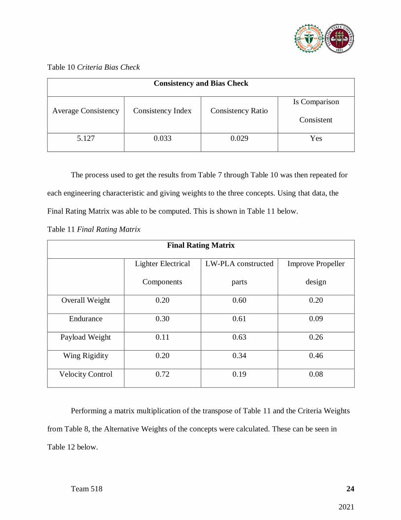
Table 10 Criteria Bias Check
Consistency and Bias Check
Average Consistency Consistency Index Consistency Ratio
Is Comparison
Consistent
5.127 0.033 0.029 Yes
The process used to get the results from Table 7 through Table 10 was then repeated for
each engineering characteristic and giving weights to the three concepts. Using that data, the
Final Rating Matrix was able to be computed. This is shown in Table 11 below.
Table 11 Final Rating Matrix
Final Rating Matrix
Lighter Electrical
Components
LW-PLA constructed
parts
Improve Propeller
design
Overall Weight 0.20 0.60 0.20
Endurance 0.30 0.61 0.09
Payload Weight 0.11 0.63 0.26
Wing Rigidity 0.20 0.34 0.46
Velocity Control 0.72 0.19 0.08
Performing a matrix multiplication of the transpose of Table 11 and the Criteria Weights
from Table 8, the Alternative Weights of the concepts were calculated. These can be seen in
Table 12 below.

Team 518 25
2021
Table 12 Alternative Weight of Concepts
Alternative Weight of Concepts
Concepts Alternative
Lighter Electrical components 0.401
LW-PLA Constructed parts 0.352
Improve Propeller design 0.242
The alternative values are determined using the Final Rating Matrix in Table 11 and the
Criteria Weights in the second column of Table 9. The alternative values reveal the ranking of
the concepts compared to one another. The highest-ranking concept from table 12 is the Lighter
Electrical Components concept with a .401 ranking. From our Pugh charts, the top two concepts
were consistently LW-PLA constructed parts and Lighter Electrical Components. This
conclusion matches the conclusion from the Pugh charts. The top two concepts from the
iterations of the Pugh charts were the top two concepts in Table 12. Therefore, the Lighter
Electrical Components concept is the best concept to meet the project objective.
Selected Concept
Out of all the concepts generated by Team 518 to best meet our project objective, the best
concept is to introduce lighter electrical components to the existing UAV. Introducing a smaller,
lighter battery and motor can help reduce the weight of the UAV. Using the tools to select the
concepts, this was found to be the best concept to lightweight the UAV, increasing the flight
time, and providing surveillance data. However, the light weighting process is very iterative.
Changing one piece of the design can allow you to reduce the weight in other areas outside of
what you directly improved. When we improve the electrical components of the Believer 1960,

Team 518 26
2021
reducing the weight, we then will not need to have as strong of a support structure for those
parts. That allows for weight to be reduced in the support structure. This kind of process and
analysis can be applied to many of the UAV’s systems.
1.8 Spring Project Plan
The figure below shows the project plan for the spring semester.
Figure 2 Spring Project Plan
Utilizing a Gantt chart, we were able to create a plan to complete our project for the
spring semester. The blue boxes are project tasks, the red boxes are design review presentations,
and the green boxes are meetings with sponsors and advisors. This plan is to keep us on track
and ensure the project is completed by Engineering Design Day at the end of the spring semester.

Team 518 27
2021
Chapter Two: EML 4552C
2.1 Restated Project Definition and Scope
Project Description:
The objective of this project is to use multiple light-weighting techniques to
reduce the overall weight of a UAV and increase the flight time.
Key Goals:
The key goals of this project are objectives the team intends to meet to
accomplish the overall objective. These goals include keeping the UAV lightweight compared to
market ready UAV’s, ensuring the UAV can be easily transported and operated, and the UAV
will provide quality surveillance recordings. These goals can be influenced by and tailored to
meet the primary and secondary markets of the product.
Markets:
The markets for this project are those that the lightweight UAV can be used in. These markets
include primary and secondary markets. The lightweight UAV is mainly designed to be used in
the primary markets, but the members of the secondary markets also have an interest in the
product too. The primary market of this project are farmers and members of the agricultural
community. Secondary markets for this project include the US Military, infrastructure
companies, hobbyists, land surveyors, and teaching facilities.
Assumptions:
For the project, assumptions are made based on the objective. The assumptions
allow the designers to meet the objective while not having to designate some parameters. The
Team 518 28
2021
assumptions will not need to be investigated or verified by the team, as they are assumed to be
correct and understood. The assumptions made by the team are listed below.
• The UAV will be operated in Earth’s atmosphere.
• The flight conditions are typical of the climates in the United States.
• The UAV is remotely controlled.
• The UAV is category 1, as defined by the Department of Defense.
o A category 1 UAV has a maximum gross takeoff weight within 0-20lbs, normal
operating altitude less than 1,200ft AGL (above ground level), and an airspeed
less than 100 knots.
• The UAV will be flown in clear airspace.
• The UAV will follow all state and federal laws.
• The UAV will be flown in a limited space around other equipment, buildings, and power
lines.
• The UAV will be used by non-professionals.
• The UAV will remain in the line of sight of the user.
Stake Holders:
The stake holders for this project are those that are directly influenced by the work done
to develop the lightweight UAV. These parties have invested resources, interests, or control of
the outcome of the lightweight UAV. For this project, the stakeholders are:
• Northrop Grumman
• Dr. Shayne McConomy
• Dr. Lance Cooley
Team 518 29
2021
• Senior Design Team 518
• Florida Department of Agriculture
• Keith Dixon (Florida farmer/possible customer)
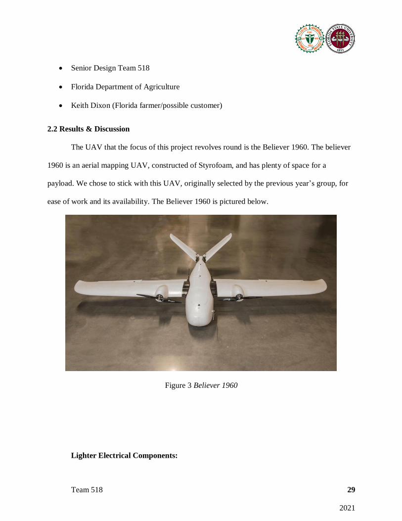
2.2 Results & Discussion
The UAV that the focus of this project revolves round is the Believer 1960. The believer
1960 is an aerial mapping UAV, constructed of Styrofoam, and has plenty of space for a
payload. We chose to stick with this UAV, originally selected by the previous year’s group, for
ease of work and its availability. The Believer 1960 is pictured below.
Figure 3 Believer 1960
Lighter Electrical Components:

Team 518 30
2021
From the 2019-2020 Team 518 that originally started this project, we inherited two
batteries. The batteries that we worked with were the Turnigy 20,000mAh 14.8v battery and the
Lumenier 22,000mAh 14.8v battery. The two batteries are pictured below.
Figure 4 Turnigy and Lumenier Batteries
The Believer came with a manual that recommended parts to implement to fly the UAV. The
manual recommends the Turnigy battery be used due to its large capacity and voltage rating. The
Lumenier battery was the battery selected previously as the lighter battery to replace the Turnigy
battery due to it being lighter. The Turnigy battery weighed 1729 grams while the Lumenier
battery weighed 1702 grams. This resulted in 27 grams of weight savings and a greater flight
time due to the 2000mAh extra capacity. One thing to note about the batteries is the difference in
their size and weight from the manufacturer compared to what we recorded. The Turnigy battery
was actually smaller and weighed less than what the manufacturer said. The Lumenier battery
was bigger and weighed more than what its manufacturer reported. If the manufacturers data was
correct, the implementation of the Lumenier battery would have a far greater impact on the

Team 518 31
2021
weight savings. At first, we noted the Lumenier battery would reduce the weight of the UAV by
175 grams. That is a large difference from the actual 27 grams it saved.
The second part of the electrical system that was analyzed to be replaced by lighter
components was the motors. The motors that were recommended for the Believer were the
SunnySky X2814 900kv motors. These motors weighed 110 grams each but are suited for large
drone applications like the believer. Through research we decided to replace these motors with
the iFlight XING X2814 880kv motors.
Figure 5 iFlight XING x2814 880kv Motor
These motors rotate at nearly the same speed, are also suited for large drone applications, and
weigh just 91 grams per motor. Utilizing these motors, we were able to save 38 grams. All in all,
switching to lighter electrical components reduced the weight of the Believer 1960 by 65 grams.
Improved Propeller Construction:
Team 518 32
2021
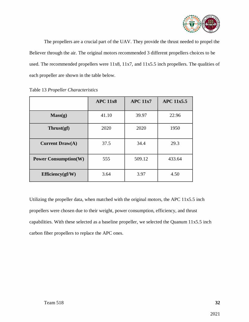
The propellers are a crucial part of the UAV. They provide the thrust needed to propel the
Believer through the air. The original motors recommended 3 different propellers choices to be
used. The recommended propellers were 11x8, 11x7, and 11x5.5 inch propellers. The qualities of
each propeller are shown in the table below.
Table 13 Propeller Characteristics
APC 11x8 APC 11x7 APC 11x5.5
Mass(g) 41.10 39.97 22.96
Thrust(gf) 2020 2020 1950
Current Draw(A) 37.5 34.4 29.3
Power Consumption(W) 555 509.12 433.64
Efficiency(gf/W) 3.64 3.97 4.50
Utilizing the propeller data, when matched with the original motors, the APC 11x5.5 inch
propellers were chosen due to their weight, power consumption, efficiency, and thrust
capabilities. With these selected as a baseline propeller, we selected the Quanum 11x5.5 inch
carbon fiber propellers to replace the APC ones.
Team 518 33
2021
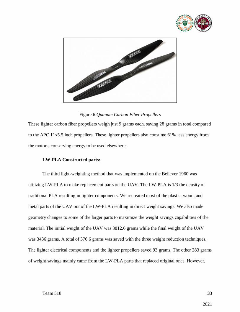
Figure 6 Quanum Carbon Fiber Propellers
These lighter carbon fiber propellers weigh just 9 grams each, saving 28 grams in total compared
to the APC 11x5.5 inch propellers. These lighter propellers also consume 61% less energy from
the motors, conserving energy to be used elsewhere.
LW-PLA Constructed parts:
The third light-weighting method that was implemented on the Believer 1960 was
utilizing LW-PLA to make replacement parts on the UAV. The LW-PLA is 1/3 the density of
traditional PLA resulting in lighter components. We recreated most of the plastic, wood, and
metal parts of the UAV out of the LW-PLA resulting in direct weight savings. We also made
geometry changes to some of the larger parts to maximize the weight savings capabilities of the
material. The initial weight of the UAV was 3812.6 grams while the final weight of the UAV
was 3436 grams. A total of 376.6 grams was saved with the three weight reduction techniques.
The lighter electrical components and the lighter propellers saved 93 grams. The other 283 grams
of weight savings mainly came from the LW-PLA parts that replaced original ones. However,
Team 518 34
2021
optimizing the amount of glue applied and the length of wires in the electrical system is a part of
that 283 grams.
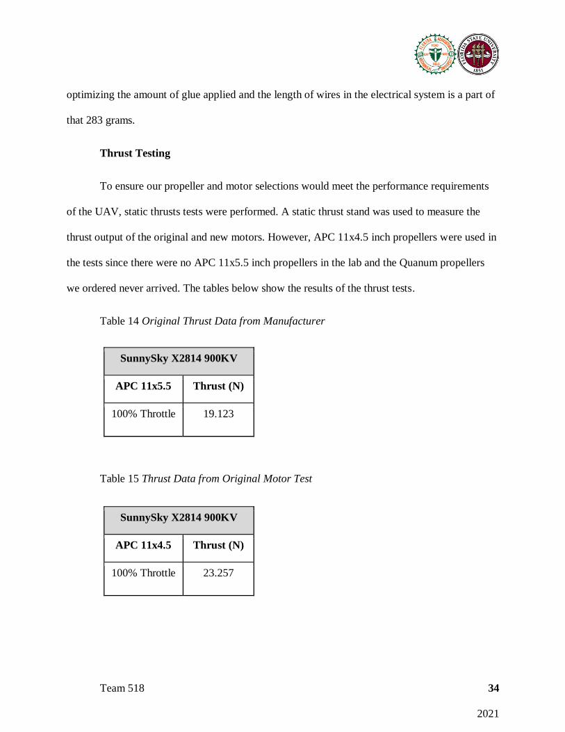
Thrust Testing
To ensure our propeller and motor selections would meet the performance requirements
of the UAV, static thrusts tests were performed. A static thrust stand was used to measure the
thrust output of the original and new motors. However, APC 11x4.5 inch propellers were used in
the tests since there were no APC 11x5.5 inch propellers in the lab and the Quanum propellers
we ordered never arrived. The tables below show the results of the thrust tests.
Table 14 Original Thrust Data from Manufacturer
SunnySky X2814 900KV
APC 11x5.5 Thrust (N)
100% Throttle 19.123
Table 15 Thrust Data from Original Motor Test
SunnySky X2814 900KV
APC 11x4.5 Thrust (N)
100% Throttle 23.257

Team 518 35
2021
Table 16 Thrust Data from New Motor Test
iFlight XING 2814 880KV
APC 11x4.5 Thrust (N)
100% Throttle 19.735
The thrust tests proved that the new motors would work on the Believer 1960.
Even though they produce slightly less thrust than shown in the original motor test, the test
performed on the new motors showed that they supply more force than what is stated by the
original motor manufacturer. The 11x5.5 inch carbon fiber propellers never arrived to be tested
but with a more aggressive pitch than the propellers used in testing, they would provide a greater
amount of thrust and be suitable for this application.
LW-PLA Part Testing
Stated previously, the geometry of most of the parts that were replaced by LW-PLA
constructed ones was never changed. However, the geometry of the wing and empennage
connecting pieces were changed. The original wing connecting pieces are pictured below.
Team 518 36
2021
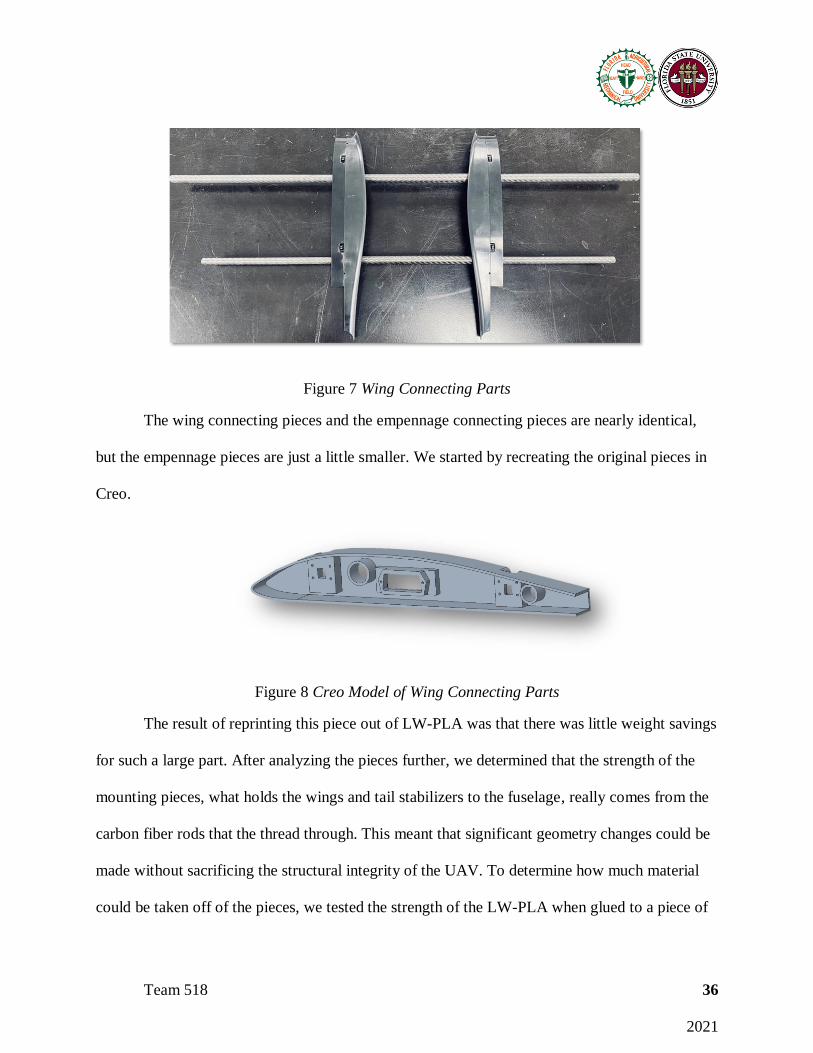
Figure 7 Wing Connecting Parts
The wing connecting pieces and the empennage connecting pieces are nearly identical,
but the empennage pieces are just a little smaller. We started by recreating the original pieces in
Creo.
Figure 8 Creo Model of Wing Connecting Parts
The result of reprinting this piece out of LW-PLA was that there was little weight savings
for such a large part. After analyzing the pieces further, we determined that the strength of the
mounting pieces, what holds the wings and tail stabilizers to the fuselage, really comes from the
carbon fiber rods that the thread through. This meant that significant geometry changes could be
made without sacrificing the structural integrity of the UAV. To determine how much material
could be taken off of the pieces, we tested the strength of the LW-PLA when glued to a piece of
Team 518 37
2021
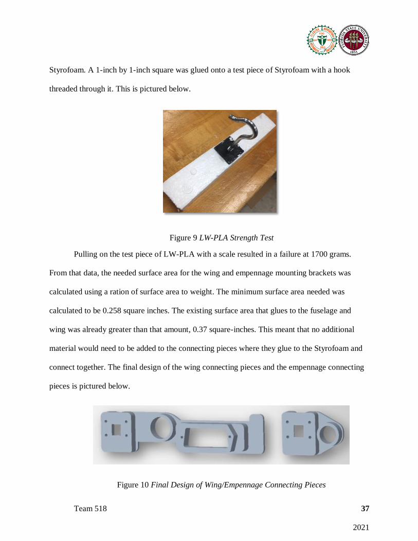
Styrofoam. A 1-inch by 1-inch square was glued onto a test piece of Styrofoam with a hook
threaded through it. This is pictured below.
Figure 9 LW-PLA Strength Test
Pulling on the test piece of LW-PLA with a scale resulted in a failure at 1700 grams.
From that data, the needed surface area for the wing and empennage mounting brackets was
calculated using a ration of surface area to weight. The minimum surface area needed was
calculated to be 0.258 square inches. The existing surface area that glues to the fuselage and
wing was already greater than that amount, 0.37 square-inches. This meant that no additional
material would need to be added to the connecting pieces where they glue to the Styrofoam and
connect together. The final design of the wing connecting pieces and the empennage connecting
pieces is pictured below.
Figure 10 Final Design of Wing/Empennage Connecting Pieces

Team 518 38
2021
The new design retains the holes for the carbon fiber rods to maintain strength, the hole
for the wiring harnesses to connect, and the locations of the hooks that snap the two sides
together. The drastic geometry change had a significant impact on the weight savings.
Energy Analysis
The energy consumed by the UAV before and after the weight savings was analyzed. The
first part of this process was to analyze the force that act on the UAV. The force of lift, the force
of drag, the force of thrust, and the force of gravity all act on the UAV as it flies. These are
pictured below.
Figure 11 Forces Acting on UAV
The forces are used to analyze the energy consumed by the UAV. The energy can be calculated
by taking the integral of the force times the velocity over time.
𝐸 = ∫ 𝐹𝑣 𝑑𝑡
Team 518 39
2021
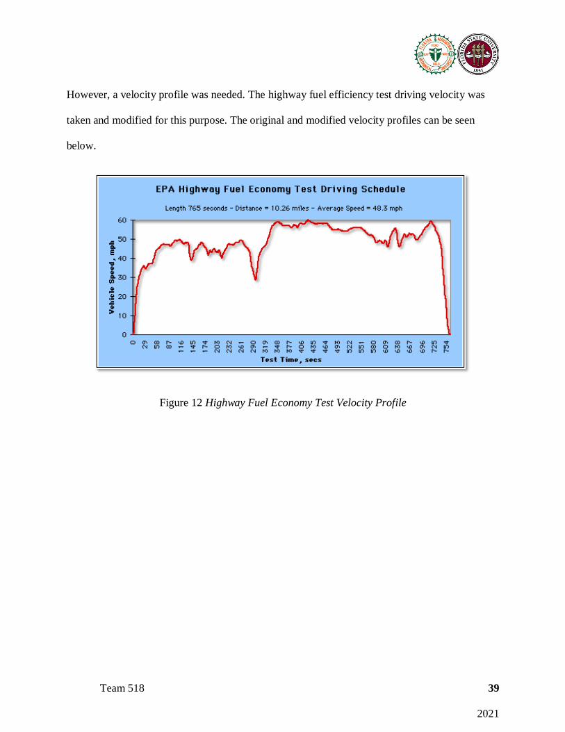
However, a velocity profile was needed. The highway fuel efficiency test driving velocity was
taken and modified for this purpose. The original and modified velocity profiles can be seen
below.
Figure 12 Highway Fuel Economy Test Velocity Profile

Team 518 40
2021
Figure 13 Modified Velocity Profile
Using this velocity profile and the forces acting on the UAV, a Simulink model was created to
analyze the energy consumption. The figure below shows the energy consumption of the UAV
over time.

Team 518 41
2021
Figure 14 Energy Consumption of the UAV
The yellow line is the energy consumed by the UAV based on the original weight. After the
376.6 grams of weight savings was applied, the red line was plotted. The red line shows the
energy consumed after the weight reduction techniques were implemented resulted in an energy
decrease. The weight loss resulted in an energy consumption decrease of 10%.
After the change in weight was manipulated, a sensitivity analysis was done to see where
future energy savings could come from. The theoretical changes and the amount of energy they
save are shown in the table below.
Table 17 Future energy Savings

Team 518 42
2021
Design Changes Energy savings
800g weight savings 20%
1900g weight savings 49%
Improve CL/CD ratio to 14 0.3%
Increase CL to 1.5 0.49%
Increase CL to 2(double) 1.85%
Decrease CD to .06 0.03%
Decrease CD to 0.04(half) 0.03%
Increasing the weight reduction to 800 grams and then 1900 grams shows how much
weight plays a role in energy savings. Also, it is important to note that there is almost a 1 to 1
ration of weight savings percentage to energy savings percentage. The 376.6 grams we removed
from the UAV was nearly 10 percent and the energy consumption decrease due that was also 10
percent. When the coefficients of lift and drag were theoretically changed, they had a much
smaller impact on the energy consumption.
2.3 Conclusion
The light weighting process is very difficult. As engineers, we ran into problems that we
did not expect. Some methods of weight reduction were better than expected and some did not
work as well as we had hoped. Through completing this project, we learned the effects of weight
Team 518 43
2021
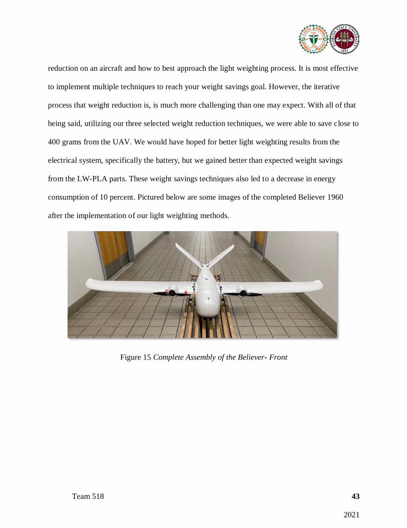
reduction on an aircraft and how to best approach the light weighting process. It is most effective
to implement multiple techniques to reach your weight savings goal. However, the iterative
process that weight reduction is, is much more challenging than one may expect. With all of that
being said, utilizing our three selected weight reduction techniques, we were able to save close to
400 grams from the UAV. We would have hoped for better light weighting results from the
electrical system, specifically the battery, but we gained better than expected weight savings
from the LW-PLA parts. These weight savings techniques also led to a decrease in energy
consumption of 10 percent. Pictured below are some images of the completed Believer 1960
after the implementation of our light weighting methods.
Figure 15 Complete Assembly of the Believer- Front
Team 518 44
2021
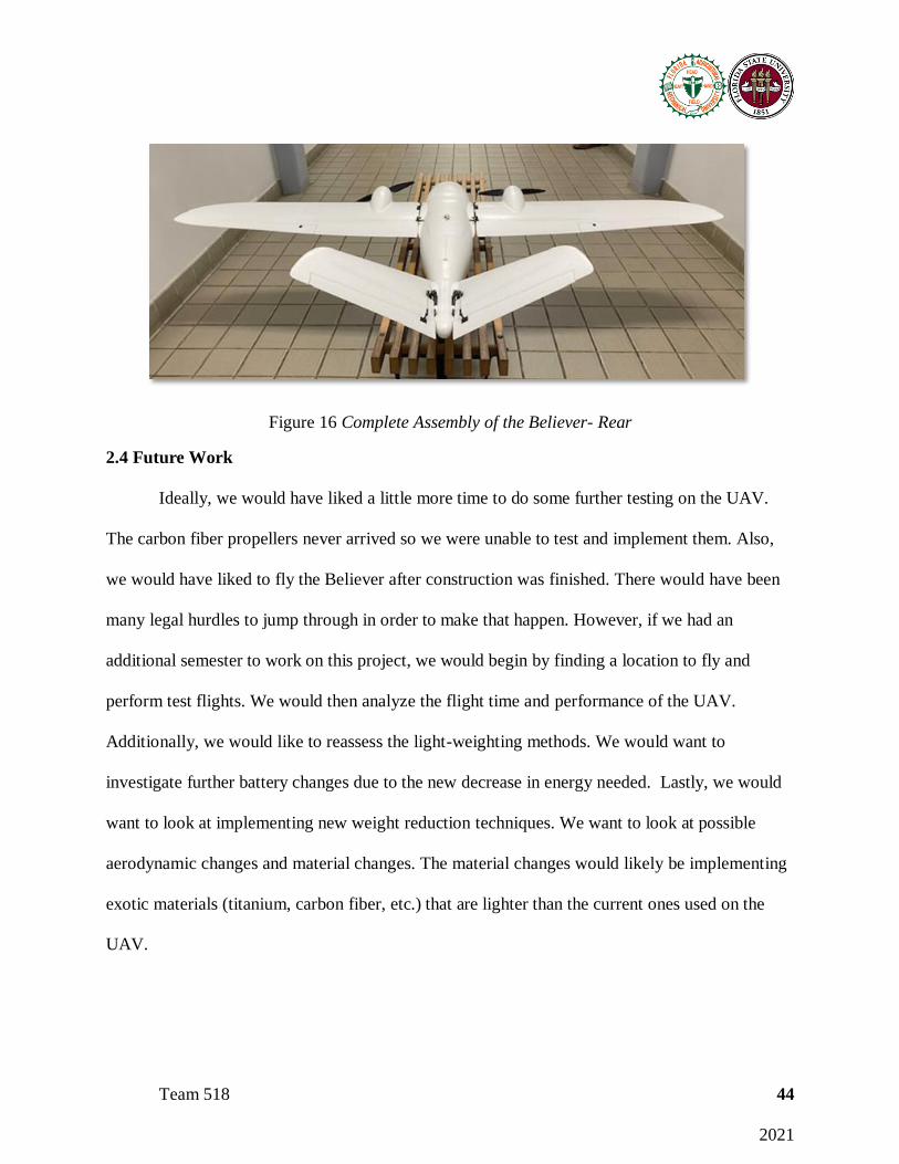
Figure 16 Complete Assembly of the Believer- Rear
2.4 Future Work
Ideally, we would have liked a little more time to do some further testing on the UAV.
The carbon fiber propellers never arrived so we were unable to test and implement them. Also,
we would have liked to fly the Believer after construction was finished. There would have been
many legal hurdles to jump through in order to make that happen. However, if we had an
additional semester to work on this project, we would begin by finding a location to fly and
perform test flights. We would then analyze the flight time and performance of the UAV.
Additionally, we would like to reassess the light-weighting methods. We would want to
investigate further battery changes due to the new decrease in energy needed. Lastly, we would
want to look at implementing new weight reduction techniques. We want to look at possible
aerodynamic changes and material changes. The material changes would likely be implementing
exotic materials (titanium, carbon fiber, etc.) that are lighter than the current ones used on the
UAV.
Team 518 45
2021
2.5 References
Classification of the Unmanned Aerial Systems. (n.d.). Retrieved September 25, 2020, from
https://www.e-education.psu.edu/geog892/node/5
Believer 1960mm Aerial Survey Aircraft - Kit. (n.d.). Retrieved October 27, 2020, from
https://www.getfpv.com/believer-1960mm-aerial-survey-aircraft-
kit.html?afid=aVlOV0hBdmd6THc9
Wales, M. (2020, October 20). Top 10 Drones with Longest Flight Time for 2020. Retrieved
October 27, 2020, from https://filmora.wondershare.com/drones/drones-with-longest-
flight-time.html
Why Fly A Fixed-Wing Drone? Reduce Time On-Site Reason 1 (INFOGRAPHIC). (2019, July
03). Retrieved October 27, 2020, from https://www.sensefly.com/2019/06/14/fixed-wing-
drone-benefit-reduce-time/
UAV Cameras: Suppliers of Cameras for UAV, Drones, UGV & Robotics. (n.d.). Retrieved
October 27, 2020, from
https://www.unmannedsystemstechnology.com/category/supplier-directory/cameras-
imaging-systems/cameras/

Team 518 46
2021
Appendices

Team 518 47
2021
Appendix A: Code of Conduct
Mission Statement
The mission of team 518 is to provide an innovative solution for Northrop Grumman that
is both cost effective and sustainable. Team 518 strives to not only meet but exceed the standards
set forth by our customer.
Team Member Roles
Ethan Hale: Manufacturing and Systems Engineer
The role of the manufacturing engineer is to ensure a high-quality product is created. The
product is ensured to meet design requirements and be operational. Part of the role as the
manufacturing engineer is also to create and integrate the many systems (mechanical and
electrical) of the product. The manufacturing engineer also strives to complete the product in the
most cost-effective manner.
John Storms: Test Engineer
Responsible for warranting high quality of the product through extensive testing and data
collection from numerous scenarios through digital/real-world simulations. Team collaboration is
essential in communicating the necessary changes to make through found errors/flaws and create
testing plans.
Maxwell Sirianni: Flight Dynamics Engineer
The role of the flight dynamics engineer is that they are responsible for the dynamics
behind the performance and control of the vehicle during flight. This role also includes
determining the necessary forces needed to keep the vehicle stable in flight, while also relaying
important information and equations to design and software engineers.
Joseph Ledo-Massey: Design Engineer, Project Manager
Team 518 48
2021
The role of the design engineer is to create new designs based on research performed by
the team and other sources. Working in parallel with all team members, the design engineer
utilizes CAD to conceptualize an innovative product that meets all the requirements put forth by
the customer. The project manager is responsible for managing the schedule, budget, and
progress of the project.
Jackson Dixon: Supply Chain Engineer
As the supply chain engineer, it will be my responsibility to assist the other members in
completing their assigned tasks by researching current products and materials available on the
market. This will include contacting the appropriate providers or representatives to get the
supplies and parts needed. Also, making sure the needed supplies will arrive on time or finding
an adequate substitute.
Role Statement:
As for duties that are not specifically assigned to an individual, the team will discuss and
agree who is to perform those duties. These discussions will take place during the daily team
meetings and each team members workload will be taken into consideration. The duties may
require knowledge beyond an individual’s current experience, but proper research is to be done
to ensure the quality of the product is maintained.
Communication
The team will communicate virtually through platforms such as Zoom, email, texting,
calling, Base Camp and GroupMe. During each meeting, notes will be taken to ensure a record
of work is established. It is expected of all team members to respond to calls, texts messages, and
emails in a timely manner (24-hours).
Dress Code

Team 518 49
2021
The dress code will be shirt and tie when presenting a formal presentation. Shirt and tie
must have the colorway of blue, white, black, grey, or neutral color. When talking to the
Northrop Grumman sponsor and our academic advisor, collared shirts and khakis are to be worn.
Attendance Policy
Team members must attend all team, sponsor, and advisor meetings, except for a planned
absence that has been communicated to all other team members. A 24-hour notice of absence is
required, and each team member is expected to show up at least 5 minutes early to every
meeting. Excused absences include, but are not limited to, what is listed in the EML 4551c
syllabus. Attendance will be recorded in the meeting notes of every gathering. If any issues arise
regarding attendance, they will be first discussed within the group. If attendance issues continue
to persist then they will be brought to the attention of Dr. McConomy.
Statement of Understanding
By signing this document, the members of team 518 agree to all the above statements and
will abide by the code of conduct set forth by the group for the remainder of the project.
Name Signature Date
Ethan Hale Ethan Hale 9/3/2020
Max Sirianni Max Sirianni 9/3/2020
John Storms John Storms 9/3/2020
Joseph Ledo-Massey Joseph Ledo-Massey 9/3/2020
Jackson Dixon Jackson Dixon 9/3/2020

Team 518 50
2021

Team 518 51
2021
Appendix B: Functional Decomposition
Table 18 Major Functions Cross Reference Table
Communication Flight Power Surveillance Structure
Communication x x x x x
Flight x x x x
Power x x x x x
Surveillance x x x x
Structure x x x x x
Table 19 Major Functions and Subfunctions Cross Reference Table
Communication Flight Power Surveillance Structure
Receive
Commands
x x x x
Flight Feedback x x x
Send Video Feed x x
Accelerate x x x x
Decelerate x x x x
Adjust Roll, Pitch,
& Yaw
x x x x
Power Flight
Controls
x x x x
Power Payload x x x x

Team 518 52
2021
Record Visual
Data
x x x
Orient Payload x x x x
Bolster Weight x x
Generate Lift x x
Store Hardware x
Couple Payload x x x

Team 518 53
2021
Appendix C: Target Catalog
Table 20 Targets and Metrics for UAV Functions
Functions Metrics Targets
Receive commands Range 1400 meters
Flight Feedback Range 1400 meters
Send Video Bandwidth
10 Mbps for HD feed
at 25 FPS
Accelerate
Accelerate from
cruising speed
2 m/s2
Decelerate
Decelerate from
cruising speed
2 m/s2
Adjust Roll, Pitch, &
Yaw
Control Ailerons,
Elevators, & Rudders
90° range of motion
Power Flight Controls
Voltage supplied by
battery
12.0 V
Power Payload
Voltage supplied by
battery
12.0 V
Record Visual Data Video Quality 2.1 Megapixels
Orient Payload
Fixed Position
Perpendicular to ground
within:
2°

Team 518 54
2021
Bolster Weight
Support moment due
to wing
1.128N/m
Generate Lift
Airfoil produces
greater lift force than gross
weight
54 Newtons
Store Hardware Volume 0.001964m3
Couple payload
Mass of payload
supported
600g
Endurance Overall Flight Time 60 mins
Transported Easily
Disassembled
Dimensions:
(L x W x H)
1100mm x 2000mm
x 200mm
Battery Capacity 22,000 mAh
Start of mission Take off force 9 Newtons
Cruising Speed Constant Velocity 20 m/s2
Appendix D: Operation Manual
The purpose of this project was to implement weight reduction techniques to reduce
the weight of a fixed-wing drone and increase the flight time. To do so, our team chose to utilize
three light-weighting techniques to meet the objective. The drone we chose to use was the
Believer 1960mm. This is an aerial mapping drone, suited for our market. It can be used for

Team 518 55
2021
surveying fields, counting cattle, and checking crop conditions. The large fuselage allows for a
camera or other payload to be used.
The first way we chose to reduce the weight was to use lighter electrical components. The
heaviest electrical component is the battery, so we began there. Using a lighter battery, we were
able to save weight and extend the flight time as the new battery had a greater electrical capacity.
After the battery, we expanded the weight reduction of the electrical system by analyzing the
motors. Implementing lighter motors, with similar speeds helped us cut weight and stay within
the recommended flight specifications.
The second way we chose to reduce the weight was to recreate parts of the UAV with
LW-PLA, which is a lightweight 3D printing filament. The heat that the filament is printed with
causes the filament to expand, reducing its density. Utilizing a less dense material means parts of
the same size weigh less. Along with this, we made geometric changes where applicable in order
to reduce the weight of the pieces even more.
The third way we chose to reduce the weight of the drone was to implement lighter
propellers. For the new propellers, we chose to utilize carbon fiber propellers. The material
change allowed us to cut the weight of the propellers in half compared to the original.
Utilizing these three techniques, we successfully reduced the weight of the Believer
1960mm drone and increased the flight time. The following details how to assemble, operate,
and fix the drone. This resource will help you operate and repair the drone if needed.
Power system
The electrical system was the first component of the drone that was analyzed. To light
weight this part of the drone, we started with the battery. The original battery was a Turnigy
20,000mAh, 4-cell, 14.8V, and 12-24C battery. We replaced it with a Lumenier 22,000mAh, 4-

Team 518 56
2021
cell, 14.8V, 12-24C battery. If the battery were to go bad, you would need to replace it with a
high mAh capacity, 4-cell, and 14.8V battery so that the system would operate at the same
specifications. This battery saved nearly 30 grams from UAV while extending its capacity by ten
percent.
If the battery were to die or run low on power, you will need to charge the battery using
the LiPo battery charger in the lab. The charger will need to be set at the correct voltage settings.
To reach full charge, the battery will need to remain on the charger for a couple of hours.
Motors
The DC motors recommended by the Believer handbook are the SunnySky X2814
900KV motors. We replaced these with the iFlight XING X2814 880KV motors. These motors
are the only source of propulsion for the drone, so they are essential. If the motors were to break,
you would need to replace them with a motor that is in the 880-1000KV range. Staying close to
the recommended motor specs ensure the motors supply enough thrust and can turn the large
propellers required for this aircraft. If you wish to have higher KV motors (higher RPM), then
additional weight will need to be taken out and the propeller size will need to decrease.
Propellers
The propellers for this UAV are 11x5.5-inch Quanum carbon fiber propellers. Using
these propellers saved weight and energy, leading to a greater flight time. Other propellers that
can be used are 11x8, 11x7, 11x5.5, and 11x4.5-inch APC propellers. In order to test the thrust
generated and to see if the new motors we selected would be suitable, we had to test with APC
11x4.5-inch propellers since the carbon fiber ones did not arrive in time. However, these
propellers proved to provide enough thrust and still saved weight from the APC 11x5.5-inch
propellers.

Team 518 57
2021
The larger pitch propellers were not selected since they consumed more energy and
weighed more while providing just slightly greater thrust. The thrust increase was not worth the
weight increase.
Wiring
The wiring is one of the more complex parts of the drone. The wiring diagram below
does a good job simplifying the many connections needed. Please refer to this diagram for any
wiring needs.
Figure 17 Wiring Diagram 1
This diagram shows how the electrical components are plugged into the power control
board, the battery, and the flight controller. If anything becomes unplugged, this can be referred
to. A single motor is shown in the diagram but the other one gets wired the exact same. Please
see the pictures below for any additional help.

Team 518 58
2021
Figure 18 Power Control Board Wiring
The thick black and red wires on the top left and right corners of the power control board
are the positive and negative terminals of the speed controllers and connect to the motors. The
first four pins on the left side show two of the servo motors plugged in. There are two empty
spots between them for the other two servo motors to go into. The first two pins are for the
servos in the wings that control the roll and the second two are for the servos in the tail that
control pitch and yaw. The two plugs at the top of the board are for power 1 and power 2 that
have corresponding slots on the PixHawk flight controller.

Team 518 59
2021
Figure 19 Flight Controller Wiring
This figure shows how the connections are managed on the PixHawk flight controller.
The top two are the two power connections that connect to the top of the power board. The wires
in the middle connect to the receiver for the controller and an air speed sensor. The thick black
wire on the right is the connection to the GPS module of the flight controller. Lastly the wire at
the bottom left connects to the PWM on the power control board.
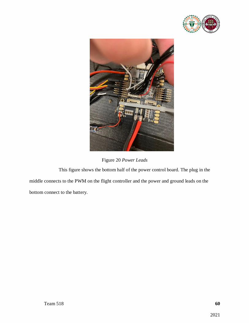
Team 518 60
2021
Figure 20 Power Leads
This figure shows the bottom half of the power control board. The plug in the
middle connects to the PWM on the flight controller and the power and ground leads on the
bottom connect to the battery.
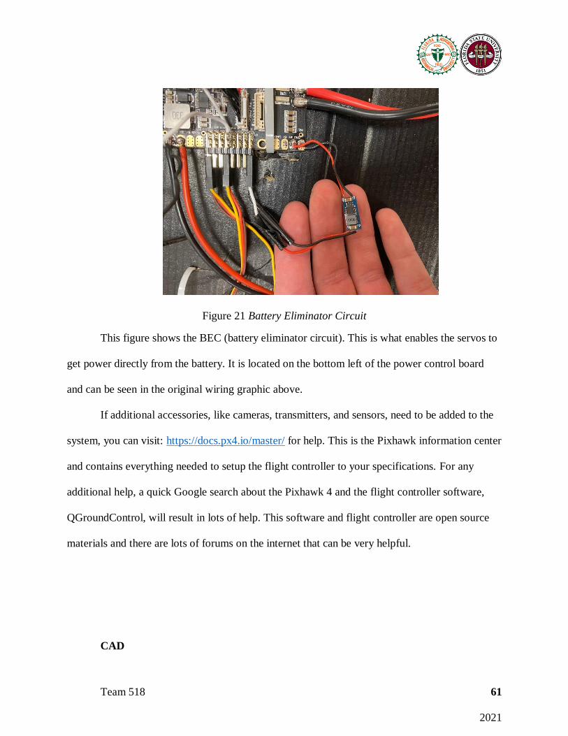
Team 518 61
2021
Figure 21 Battery Eliminator Circuit
This figure shows the BEC (battery eliminator circuit). This is what enables the servos to
get power directly from the battery. It is located on the bottom left of the power control board
and can be seen in the original wiring graphic above.
If additional accessories, like cameras, transmitters, and sensors, need to be added to the
system, you can visit: https://docs.px4.io/master/ for help. This is the Pixhawk information center
and contains everything needed to setup the flight controller to your specifications. For any
additional help, a quick Google search about the Pixhawk 4 and the flight controller software,
QGroundControl, will result in lots of help. This software and flight controller are open source
materials and there are lots of forums on the internet that can be very helpful.
CAD

Team 518 62
2021
The following CAD images are examples of the parts that were recreated using LW-PLA.
If any of the printed parts break, the original parts that came with the Believer can be referenced
to replace them.
Figure 22 Regulating Cover
Figure 23 Latching Hook
Some parts were completely redesigned to make as light as possible. These consisted of
the motor installing base, battery fixing board, servo installing bases and covers, empennage
connecting brackets, and wing connecting brackets. These parts are largely based on the original
parts and can be duplicated if examined while using the original as a reference. The wing and
empennage connecting brackets are nearly identical, just differ in size. The figure shows the
original and the new geometry of the wing connecting bracket.
Figure 24 Wing Connecting Part Design

Team 518 63
2021
If any parts CAD files are needed to replace broken parts, do not hesitate to contact
Joseph Ledo-Massey or Jackson Dixon.
3D Printer Settings
The following table shows the 3D printer settings we used to recreate the various
pieces of the drone. These settings are essential to replicating the pieces identically. We used the
Innovation Hub on FSU’s main campus for all of our 3D printing needs. Due to the kind of
material LW-PLA is, the repeatability across different kinds of 3D printers is limited. If you use
the Dremel 3D45 printer at the innovation hub and the settings below, the parts should be
identical to what is currently on the drone.
Table 21 3D Printer Settings
Print Settings
Nozzle Temperature 240 C
Flow Rate 50%
Layer Thickness 0.2 mm
Shell Thickness 0.8 mm
Infill 0%
Print Speed 40 mm/s
Part Cooling 0%
Drone Parts
There are many places to get the necessary parts to fly, improve, or repair the drone. The
listed websites below are sources for other batteries, motors, propellers, and many other parts:
https://www.getfpv.com , https://hobbyking.com/en_us

Team 518 64
2021
One tricky part of the Believer 1960 is the assembly of it. The drone comes with a
manual with performance specifications and a parts list. However, the manual does not give
assembly instructions or details. In order to assemble the drone, we referenced an online forum.
The link below is an assembly thread written by a user named Arxangel:
https://arxangelrc.blogspot.com/2017/11/believer-1960mm-professional-mapping-fpv-
platform-best-designed-aerial-platform.html
As a hobbyist, he goes in depth about the assembly of his Believer drone. One thing to
note about his assembly is that parts like the motors, servos, propellers, and batteries that are
bought separately from the Believer are different from what is recommended by the
manufacturer. If you combine this assembly thread with the manual supplied with the believer,
the drone can be assembled. The parts we changed were the motors, batteries, and propellers
from the recommended components. We used the Lumenier 22,000mAh 4s 14.8v battery, the
iFlight XING X2814 880KV motors, and 11x5.5-inch Quanum carbon fiber propellers. The rest
of the pieces were either recommended to purchase in the manual, came with the Believer, or
were reprinted out of LW-PLA using the CAD files above. The next links below provides
additional names of the Believer parts and sources to replace them.
Believer Recommended Parts, Large Parts, Small Parts
The new parts can be used to assemble the drone with the supplied parts. The hardware
from the new motors is used to attach them to their mounts on the drone but you will need to use
the x-mount that came with the old motors. Since we were in possession of the old motors, we
were able to do so. The propellers mount the motors utilizing the spacers that come with them as
well as the nut that came with the motor. For the battery, we sourced double sided tape to secure
it to the battery mounting plate. Velcro could have been used as well. For all of the plastic pieces
Team 518 65
2021
and the pieces that we created with the LW-PLA material, we used the glue that was provided
with the Believer to secure them into their respective places. Using the online thread, we were
able to successfully assemble the drone.
To safely and properly operate the Believer 1960mm, the operators should become
familiar with all aspects of the drone and proper flying procedures. It is recommended that
someone with drone operating experience fly this drone. It should be flown in an open area with
no obstructions like trees, buildings, or powerlines. Be sure to notify appropriate local
municipalities, and school personnel of your activities and location. Some areas, specifically the
college of engineering, are too close to the airport to operate the UAV at. Always be aware of
your surroundings and where people are around you. Before flying, double check that the wings
and empennages are securely mounted to the fuselage and that the latching hooks are locked in
place. Then inspect the motor assembly and propellers before starting them to make sure they are
properly assembled. Also check that the servo motors are mounted properly to the ailerons and
that they work properly. The operation of the Believer 1960mm drone begins with plugging in
and securing the battery. For the motor and control functions to be initialized, the user must first
turn off the safety switch located on the PixHawk 4 flight controller (see figure below). The LED
indicator on the flight controller will illuminate and an audible sound will indicate that the safety
has been turned on or off.

Team 518 66
2021
Figure 25 GPS Module/Safety Switch
Then the user must then prepare the Flysky FS-i6X RC Transmitter for use. The remote
controller (transmitter) should already be synced with the flight controller in the UAV. The
initialization process was done using the QGround Control flight software. The final step in
preparing the transmitter for proper use is to arm the controller. This is done by moving the left
analog stick (throttle stick) to the bottom right position for two seconds. A constant, audible
sound will be produced by the flight controller indicating that the transmitter is synced, and the
drone is armed. The RC transmitter is now ready for use. It is crucial that all users and
participants know when the system is being armed as the propellers may spin rapidly, for a
couple of seconds, after the system is armed. It is important to make sure the throttle stick is in
the lowered position to stop the propellers from spinning further until the drone is ready to take
off.
Start the motors to check that they are working properly and that the remote control is
properly synced. During operation, be aware of the vulnerable areas of the drone. The major
areas to monitor on the Believer are the wing connecting parts, empennage connecting parts,
aileron assemblies, motor and propeller mounts, and the antenna. These areas will experience
multiple stresses acting on them throughout the flight and will vary as the drone moves through
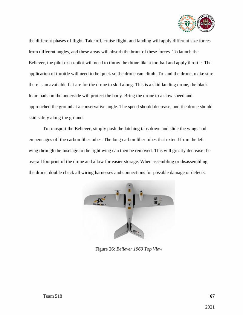
Team 518 67
2021
the different phases of flight. Take off, cruise flight, and landing will apply different size forces
from different angles, and these areas will absorb the brunt of these forces. To launch the
Believer, the pilot or co-pilot will need to throw the drone like a football and apply throttle. The
application of throttle will need to be quick so the drone can climb. To land the drone, make sure
there is an available flat are for the drone to skid along. This is a skid landing drone, the black
foam pads on the underside will protect the body. Bring the drone to a slow speed and
approached the ground at a conservative angle. The speed should decrease, and the drone should
skid safely along the ground.
To transport the Believer, simply push the latching tabs down and slide the wings and
empennages off the carbon fiber tubes. The long carbon fiber tubes that extend from the left
wing through the fuselage to the right wing can then be removed. This will greatly decrease the
overall footprint of the drone and allow for easier storage. When assembling or disassembling
the drone, double check all wiring harnesses and connections for possible damage or defects.
Figure 26: Believer 1960 Top View

Team 518 68
2021
Figure 27: Believer 1960 Side View
Listed are suggested solutions to possible issues that may arise throughout the project. If
more issues arise, please visit the Senior Design web page, and don’t hesitate to reach out to
Team 518 with more questions.
• 3-D printer must be calibrated for specific filament being used. For the LW-PLA
filament, refer to ColorFabb’s recommendation for calibrating 3D printer. Small
adjustments to the calibrated print settings may be required to optimize print quality of
full-scale parts.
• Utilize resources at Innovation Hub for 3-D printing assistance, be aware 3-D printing is
much more complex than might be anticipated.
• Failed 3-D prints occur due to a variety of factors, some associated with the printer itself
and others linked to the GCode submitted to the printers. Consult the FabLab tech at the
Innovation Hub to determine the best course of action for trouble shooting.
• If shipping delays are experienced, as should be expected, tests can still be conducted
with available parts to validate designs and testing methods.
• QGround Control can have a hard time getting a GPS lock. Make sure the flight
controller is in an open area, preferably one with good cell reception. If you are inside the
college of engineering, the flight controller will have a hard time getting a GPS lock.

Team 518 69
2021
• Sometimes you will need to reset the PixHawk flight controller in QGround Control. To
do so, you will need to keep the flight controller plugged in to the computer with the USB
cable and position the drone in the various positions shown in the screen. This resets the
orientation of the flight controller.
• If you are having trouble arming the drone, getting it ready to fly, make sure the safety
switches are turned off. The first safety switch on the PixHawk controller will need to be
pressed and then the throttle input stick on the controller will need to be pressed down
and to the right to arm the system. If the drone is not flown within 10 seconds of being
armed, the arming sequence will need to be performed again. A built-in safety
mechanism is used to prevent injury.
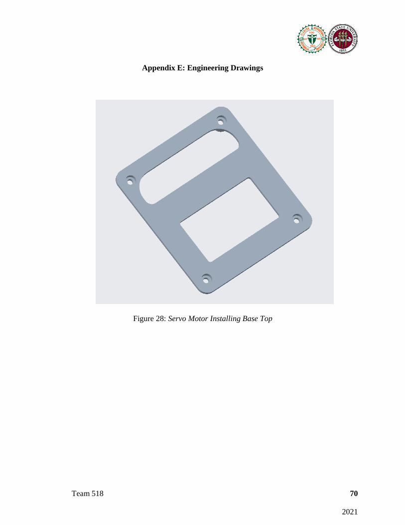
Team 518 70
2021
Appendix E: Engineering Drawings
Figure 28: Servo Motor Installing Base Top

Team 518 71
2021
Figure 29: Servo Motor Installing Base
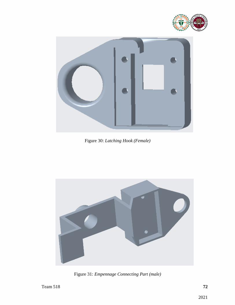
Team 518 72
2021
Figure 30: Latching Hook (Female)
Figure 31: Empennage Connecting Part (male)

Team 518 73
2021
Figure 32: Empennage Connecting Part (female)
Figure 33: Wing Connecting Part (male)
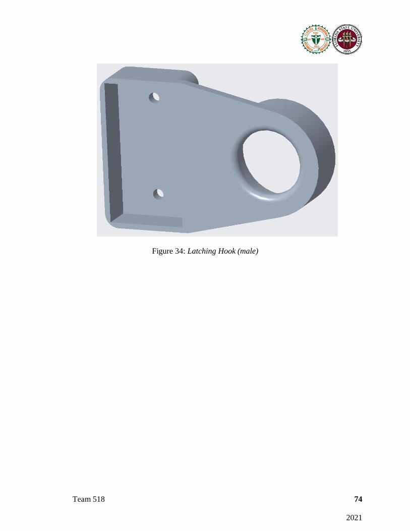
Team 518 74
2021
Figure 34: Latching Hook (male)
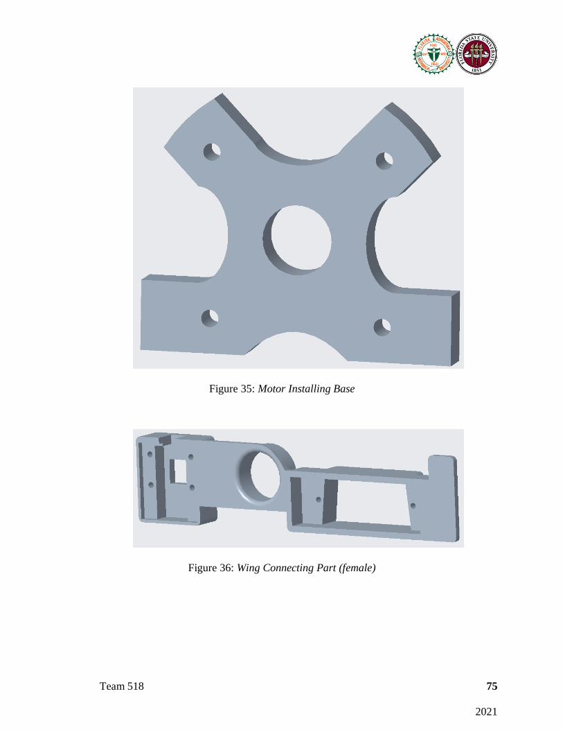
Team 518 75
2021
Figure 35: Motor Installing Base
Figure 36: Wing Connecting Part (female)
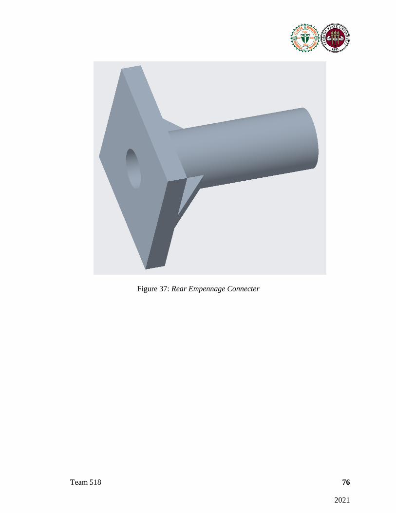
Team 518 76
2021
Figure 37: Rear Empennage Connecter

Team 518 77 2021
Appendix F: Risk Assessment
FAMU-FSU College of Engineering
Project Hazard Assessment Policy and Procedures
INTRODUCTION
University laboratories are not without safety hazards. Those circumstances or conditions that might go wrong must be predicted, and reasonable control
methods must be determined to prevent incident and injury. The FAMU-FSU College of Engineering is committed to achieving and maintaining safety
in all levels of work activities.
PROJECT HAZARD ASSESSMENT POLICY
Principal investigator (PI)/instructor are responsible and accountable for safety in the research and teaching laboratory. Prior to starting an experiment,
laboratory workers must conduct a project hazard assessment (PHA) to identify health, environmental and property hazards, and the proper control
methods to eliminate, reduce or control those hazards. PI/instructor must review, approve, and sign the written PHA and provide the identified hazard
control measures. PI/instructor continually monitor projects to ensure proper controls and safety measures are available, implemented, and followed.
PI/instructor are required to reevaluate a project anytime there is a change in scope or scale of a project and at least annually after the initial review.
PROJECT HAZARD ASSESSMENT PROCEDURES
It is FAMU-FSU College of Engineering policy to implement followings:
1. Laboratory workers (i.e. graduate students, undergraduate students, postdoctoral, volunteers, etc.) performing a research in FAMU-FSU
College of Engineering are required to conduct PHA prior to commencement of an experiment or any project change in order to identify
existing or potential hazards and to determine proper measures to control those hazards.
2. PI/instructor must review, approve, and sign the written PHA.
3. PI/instructor must ensure all the control methods identified in PHA are available and implemented in the laboratory.
4. In the event laboratory personnel are not following the safety precautions, PI/instructor must take firm actions (e.g. stop the work, set a
meeting to discuss potential hazards and consequences, ask personnel to review the safety rules, etc.) to clarify the safety expectations.
5. PI/instructor must document all the incidents/accidents happened in the laboratory along with the PHA document to ensure that PHA is
reviewed/modified to prevent reoccurrence. In the event of PHA modification a revision number should be given to the PHA, so project
members know the latest PHA revision they should follow.

Team 518 78 2021
6. PI/instructor must ensure that those findings in PHA are communicated with other students working in the same laboratory (affected users).
7. PI/instructor must ensure that approved methods and precautions are being followed by :
a. Performing periodic laboratory visits to prevent the development of unsafe practice.
b. Quick reviewing of the safety rules and precautions in the laboratory members meetings.
c. Assigning a safety representative to assist in implementing the expectations.
d. Etc.
8. A copy of this PHA must be kept in a binder inside the laboratory or PI/instructor’s office (if experiment steps are confidential).
Project Hazard Assessment Worksheet
PI/instructor: Dr. Shayne McConomy Phone #: (850) 410-6624 Dept.: ME Start Date: Revision number:
Project: Location(s): COE A212 Senior Design Lab
Team member(s): Ethan Hale, Max Sirianni, John Storms, Joseph Ledo-Masey, Jackson
Dixon
Phone #:
(904) 860-4712
Email:
Experiment Steps
Location
Person
assigned
Identify hazards
or potential
failure points
Control method PPE
List proper method
of hazardous waste
disposal, if any.
Residual
Risk
Specific rules
based on the
residual risk
Disassemble UAV and organize
parts
COE
A212 Senior
Design
Lab
Ethan
Hale, Max
Sirianni
-Using sharp
tools to open
boxes, remove packaging.
-Electrical
hazards when examining
electrical
components
-Appropriate
space provided
for user -Eye protection
provided
Long
pants,
closed toe
shoes,
eye protectio
n
N/A
HAZARD:
3
CONSEQ: Minor
Batteries
disconnected
before any work is
performed. Residual:
Low Med
Implement light weighting
techniques in the UAV
Ethan
Hale,
-Hot 3D
printers,
-Signs
implemented
Long
pants,
N/A HAZARD:
3
Always check
if 3D printers

Team 518 79 2021
COE
A212
Senior Design
Lab
Max
Sirianni,
John Storms,
Joseph
Ledo-Masey,
Jackson
Dixon
filament, and
pieces
-Electrical
hazards when connecting
systems
noting 3D
printer in use,
-Eye protection provided
-Appropriate
amount of workspace
sectioned off
closed
toe
shoes, eye
protectio
n, heat resistant
gloves
CONSEQ:
Minor
are on.
Batteries
disconnected when
connecting
electrical systems
Residual:
Low Med
Testing Electrical system
improvements
COE
A212
Senior Design
Lab
John
Storms,
Joseph Ledo-
Masey,
Jackson
Dixon
-Electrical
hazards when
connecting systems
-Heat dissipated
from electrical
systems -Spinning
motors at high
speeds
-One person
operating
system at a time.
-Teammates
monitor for
failures -Eye protection
provided
-Appropriate amount of
workspace
sectioned off
Long
pants,
closed toe
shoes,
eye
protection
N/A HAZARD:
3
CONSEQ: Moderate
Batteries
disconnected
before any work is
performed. Residual:
Medium
Reassembly of UAV and systems
COE
A212
Senior Design
Lab
Ethan
Hale,
Max Sirianni,
John
Storms,
Joseph Ledo-
Masey,
Jackson Dixon
-Electrical
hazards when
connecting systems
-Pinching due to
connecting
components
-Eye protection
provided
-Appropriate amount of
workspace
sectioned off
Long
pants,
closed toe
shoes,
eye
protection
N/A HAZARD:
3
CONSEQ: Minor
Batteries
disconnected
before any work is
performed. Residual:
Low Med

Team 518 80 2021
Principal investigator(s)/ instructor PHA: I have reviewed and approved the PHA worksheet.
Name Signature Date Name Signature Date __________________________________
____________________ ____________ __________________________________
____________________ ____________
Team members: I certify that I have reviewed the PHA worksheet, am aware of the hazards, and will ensure the control measures are followed.
Name Signature Date Name Signature Date
________Ethan Hale_________
____Ethan Hale____ ___11/29__ _______ John Storms_______ ____ John Storms____ ___11/29__
_____Joseph Ledo-Massey _ Joseph Ledo-Massey _ ___11/29__
_______Jackson Dixon______
____Jackson Dixon___
___11/29__
_____ Max Sirianni_______ _____Max Sirianni____ ___11/29__

Team 518 81
2021
Project Hazard Control- For Projects with Medium and Higher
Risks Name of Project: Light weight UAV Date of submission: 12/4/2020
Team member Phone number e-mail
Ethan Hale (904) 860-4712 [email protected]
Max Sirianni (630) 418-8002 [email protected]
John Storms (706) 701-0616 [email protected]
Joseph Ledo-Masey (850) 294-9937 [email protected]
Jackson Dixon (850) 902-0452 [email protected]
Faculty mentor Phone number e-mail
Dr. Shayne McConomy (850) 410-6624 [email protected]
Rewrite the project steps to include all safety measures taken for each step or combination of steps.
Be specific (don’t just state “be careful”).
Disassemble UAV and organize parts:
This step of the experiment includes opening all the packages the items were shipped in, organizing the
materials, and noting what has arrived and what has not. During this step in the project, batteries may be
handled so it is important to ensure they are not in use. Sharp objects used to open packages may be handled
at this point, so it is important wear safety glasses, long pants, and closed toe shoes. Blades should be
pointed away from yourself and your teammates. When not in use, make sure all blades are covered by
correct casing/enclosure. It is also important to only use cutting tools in the way they are intended to be
used.
Implement light weighting techniques in the UAV:
This step of the experiment involves the main procedures that will be used in the experiment to complete our
objective. To implement light weighting techniques in the UAV, we will be handling hot 3-D printers, hot
filaments, and hot printed pieces of the UAV. In addition to hot 3-D printing materials there is also the
electrical hazards when connecting systems together. In order to keep ourselves protected during this stage
of the project we will need to first place signs noting that 3-D printers are in use. Then we will need to
provide an appropriate amount of workspace sectioned off, so nobody needs to get close and accidently
hurts themselves. In addition to these spacing procedures, long pants, closed toe shoes, eye protection, and
heat resistant gloves should be always worn when operating the 3-D printers. When connecting the electrical
systems all the same clothing and Personal protective equipment should be worn. In order to keep everyone
safe only one person should be connecting electrical systems at a time. In addition to one person operating
Team 518 82
2021
on the electrical systems at a time, teammates should be watching whoever is working on the electrical
system monitoring for any failures or hazards.
Testing Electrical system improvements:
This step includes testing all the electrical components that make up the UAV. The electrical components
include the power source, flight controls, communications, and surveillance. To ensure this step is
performed in a safe manner the operator will verify all electrical connections are correct and all moving
parts are clear from obstructions before connecting the power source and performing the test.
Reassembly of UAV and systems:
This step consists of reassembling the UAV after all of the systems have been tested. Safety precautions will
be taken to minimize potential risks during this step. These precautions include wearing appropriate clothing
(closed toe shoes, pants, long sleeve shirt, gloves, and eye protection), following standard guidelines for
handling various tools/objects, and aware of your surroundings.
Thinking about the accidents that have occurred or that you have identified as a risk, describe
emergency response procedures to use.
All personnel using or near the laboratory equipment will follow standard safety procedures and will wear
appropriate Personal Protective Equipment. Closed toe shoes, long pants, or skirts which fully cover the legs
are required at all times when in the lab. OSHA's eye and face protection standard, 29 CFR 1910.133,
requires the use of eye and face protection when personnel are exposed to eye or face hazards such as flying
objects or other hazardous materials.
Cut or Impalement:
For shallow cuts and pricks, ensure no foreign debris is in wound. Wash wound thoroughly using soap and
water to remove any debris. Apply bandage and check to see that bleeding is not profuse.
For deep cuts or impalement, notify others immediately and turn off all involved equipment. If impaled, do
not remove item. Apply clean bandage around area to mitigate bleeding from wound and contact emergency
services and wait for their arrival.
Eye Irritation:
In the case of debris contacting eyes, turn off equipment and notify others in case of impaired vision. Go to
sink or eye wash station and attempt to flush eyes with water for a few minutes. If metal debris is in eye,
contact emergency services to remove object and treat injuries.
Electrical Shock:

Team 518 83
2021
If electrical shock occurs, turn off source of shock and notify others. Check for burn at contact point and
clean area with soap and water. Apply burn ointment and bandage if low degree of burn. If burn appears to
be high degree contact emergency services.
List emergency response contact information:
• Call 911 for injuries, fires, or other emergency situations.
• Call your department representative to report a facility concern or to report and incident.
Name Phone number Faculty or other COE emergency
contact Phone number
Cory Stanley (850) 566-4472 Dr. Shayne McConomy (850) 410-6624
Dr. Lance Cooley (850) 645-7485
Safety review signatures:
Team member Date Faculty mentor Date
Ethan Hale 11/30/20 Dr. Lance Cooley 11/30/20
Max Sirianni 11/30/20
John Storms 11/30/20
Joseph Ledo-Masey 11/30/20
Jackson Dixon 11/30/20
Report all accidents and near misses to the faculty mentor.
Recommended