In-Vehicle TestingIncreasing demand from upcoming legislationsand development trends
AVL Instrumentation & Test Systems
AVL Particulate and On-Board Emission Forum 2013
Carlos CarocaAVL Italia

NEW - M.O.V.E Mobile Testing PlatformNEW - M.O.V.E Mobile Testing Platform

WHY IN-VEHICLE TESTING?

MARKET DRIVERS
Reduction of CO2 Emission
Fuel Economy
Compliance to Emission Standards
Branding (Driving Comfort / Fun)
Profitability / Economic Sucess
Electrification

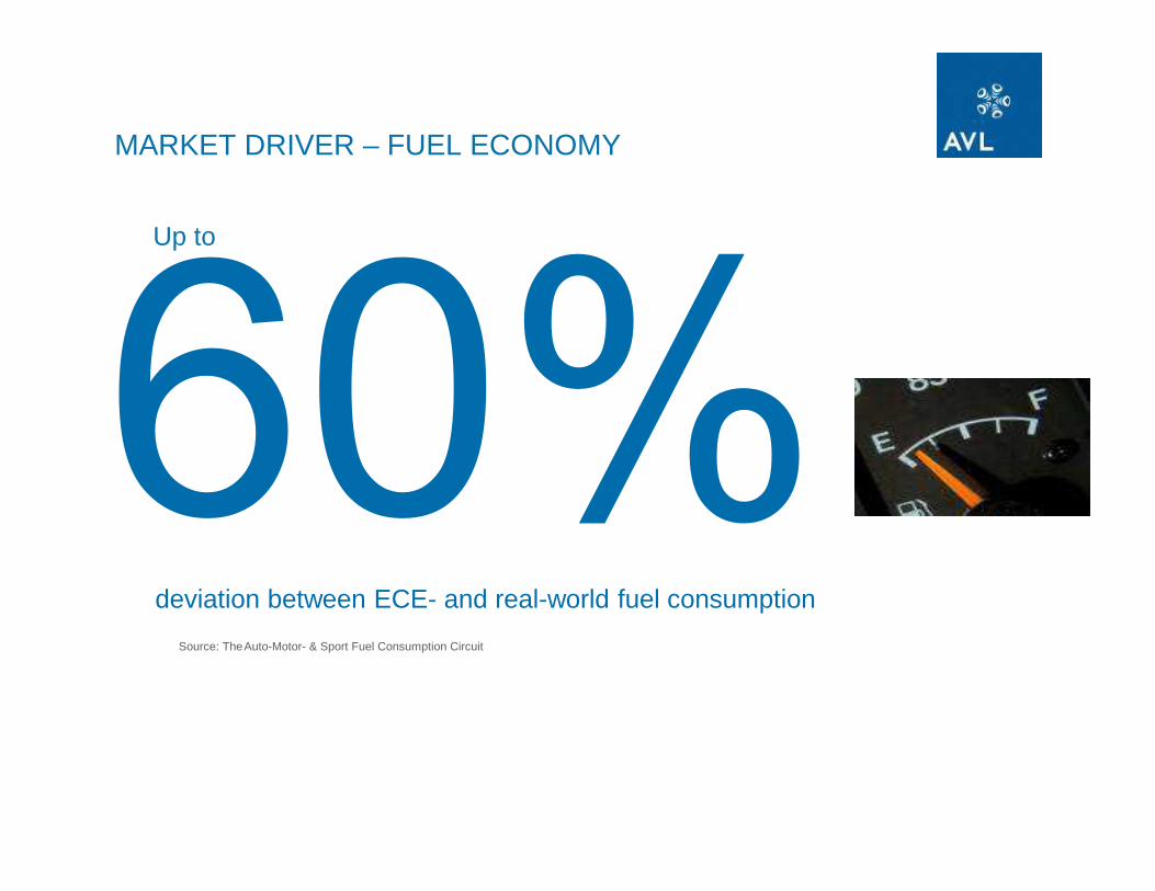
MARKET DRIVER – FUEL ECONOMY
deviation between ECE- and real-world fuel consumption
Up to
Source: TheAuto-Motor- & Sport Fuel Consumption Circuit

IMPORTANCE OF IN-VEHICLE TESTING
of development work is done on the road
Approximately
Source : AVL customer survey
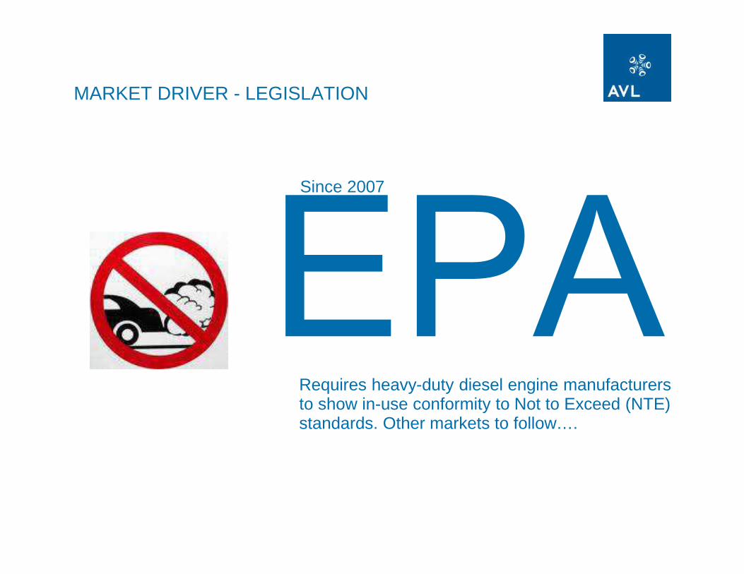
MARKET DRIVER - LEGISLATION
Requires heavy-duty diesel engine manufacturers to show in-use conformity to Not to Exceed (NTE) standards. Other markets to follow….
Since 2007

EMISSION TRENDS Further reduction of emissions
• Conventional test bed type certification test
• Unknown and random test cycle
• Can be repeated for development purpose
• Testing under real vehicle customer operation conditions with portable measurement systems
• Snap shot type of test• Can not be repeated for
development purpose, but can be repeated on test bed (Seamless integration required between portable- and test bed systems.)
Off-Cycle Emissions
In-Serviceconformity
Euro-VI Heavy Duty Test cycle
AVL M.O.V.E Test systems
Typically in Off-Cycle and In-Service testing the normal test bed limitsmust not be exceeded by more than 50%.

2007 2008 2009 2010 2011 2012 2013
Gaseous
PM
Gaseous
PM
Gaseous/ PM/Soot
Research programPilot programReview & finalization
Implementation/ transition phase
Fully in force? Planed
In-Use Legislation World Wide Roadmap
?
RDE “kicked off” 29.9.11
2014 2015 2016 2017Review
??
?
RDE 1. Step(monitoring)
interim rules
?
RDE 2. Step(limit)
PEMS Test @ TA

6+EU
EURO 6+ Real Driving Emissions (RDE)
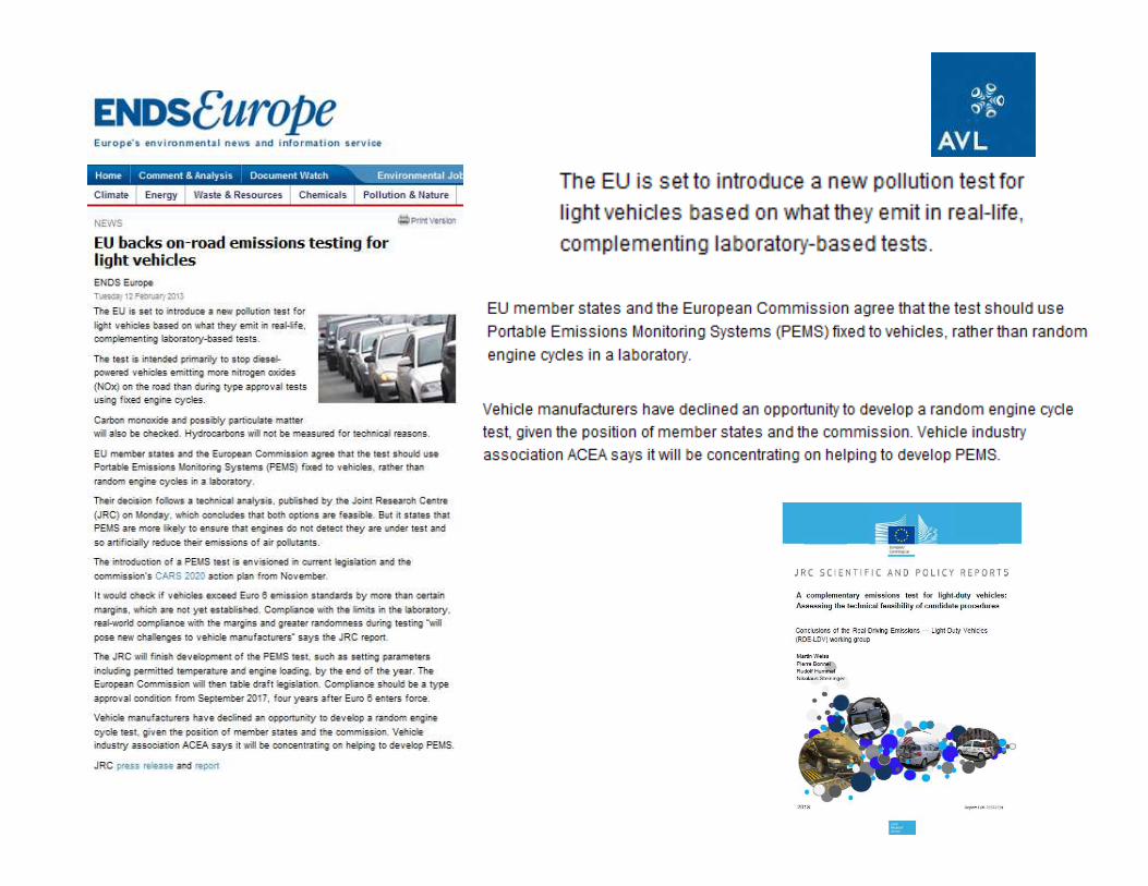

Test Procedures:� PEMS testing is defined from European Community & Member States as method for
type approval and service conformity (ISC)� random cycle (RC) method is put on ice as not all real driving conditions can be
reproduced by the RC (road grade, curves, rain, altitude, temperature etc.) � Altitude up to 1500m added� Exact procdure will be defined by joint test programm led by JRC within 2013
Measurement Targets� NOx (main target for Diesel)� CO� Particulate Number (if possible by PEMS)* (main target for GDI)� HC (optional)
RoadmapASAP Test boundaries to be definedBeg 2013 Start Fleet Tests in Europe by JRC
Includes Diesel, Gasoline & Hybrid Cars2013 Testmethode readyBeg 2014 OEM need to oficially provide test results (wihtout limits) - STEP 12017 Testing fully in force with limits - STEP 2
* PN PEMS programm is started to identify possible portable particulate counting systemApril 2013. AVL is part of it.
Light Duty - Road Map RDE ProjectStakeholder Workshop 2012.12.18
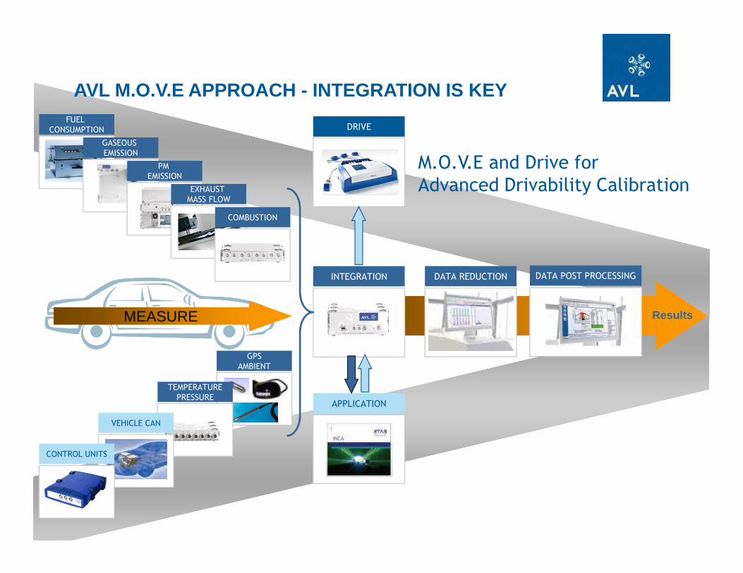
IN-VEHICLE TESTING

FUEL
CONSUMPTION
AVL M.O.V.E APPROACH - INTEGRATION IS KEY
Results
GASEOUS
EMISSION
INTEGRATION
APPLICATION
PM
EMISSION
EXHAUST
MASS FLOW
GPS
AMBIENT
TEMPERATURE
PRESSURE
MEASURE
VEHICLE CAN
CONTROL UNITS
COMBUSTION
DATA POST PROCESSINGDATA REDUCTION
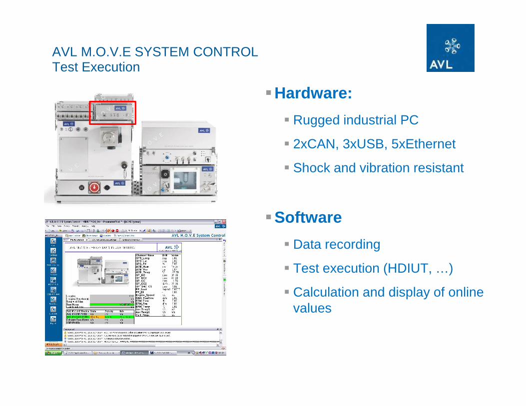
AVL M.O.V.E SYSTEM CONTROLTest Execution
�Hardware:
� Rugged industrial PC
� 2xCAN, 3xUSB, 5xEthernet
� Shock and vibration resistant
�Software
� Data recording
� Test execution (HDIUT, …)
� Calculation and display of online values

M.O.V.E System ControlLegislative Testing – HDIUT – Overview
� Test-Sequence
� Step 1:Test Preparation
� operate devices
� control device states
� use DUIs
� Step 2: Pre Test Checks
� Leak Check
� Zero + Span Adjust
� Step 3: Main Test Execution
� Cyclic Zero
� Step 4: Post Test Checks
� Zero + Span Check
� Step 5: Data Evaluation
� Save/Load/Display/Export Data
� Step 6: Post-Process Data (using Concerto + PEMS Post Processing)
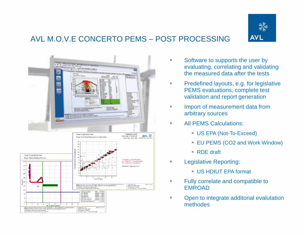
AVL M.O.V.E CONCERTO PEMS – POST PROCESSING
� Software to supports the user by evaluating, correlating and validating the measured data after the tests
� Predefined layouts, e.g. for legislative PEMS evaluations, complete test validation and report generation
� Import of measurement data from arbitrary sources
� All PEMS Calculations:
� US EPA (Not-To-Exceed)
� EU PEMS (CO2 and Work Window)
� RDE draft
� Legislative Reporting:
� US HDIUT EPA format
� Fully correlate and compatible to EMROAD
� Open to integrate additonal evalutationmethodes
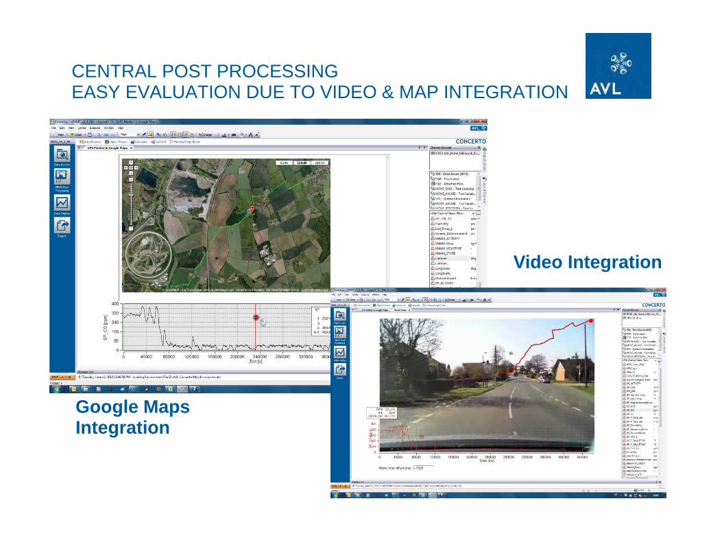
CENTRAL POST PROCESSINGEASY EVALUATION DUE TO VIDEO & MAP INTEGRATION
Video Integration
Google MapsIntegration

LIVE / DiscussionLIVE / Discussion

AVL M.O.V.E PM PEMS

� Filter holder for 47mm particulate filters
� Constant dilution
� Option: Proportional dilution NEW! (Q4/2013)
� Dilution air conditioning
� TE cooler, water trap/ condensate pump, active carbon and HEPA filter
� Temperature conditioning (heated compartments with ventilation):
� Filter compartment
� MFDs, dilution cell, heated line
� Filter overloading protection (bypass, soot mass monitoring)
� Easy access to the particulate and the other filters during regular maintenance
� Full set of diagnosis feature e. g. relative calibration of the MFC against the CFOs
AVL M.O.V.E PM PEMSGravimetric Filter Module
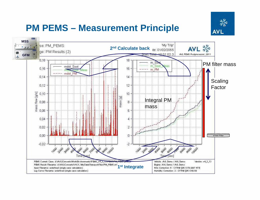
PM PEMS – Measurement Principle
Temperature Correction
PM filter mass
Integral PM mass
1st Integrate
Scaling Factor
47mm Filter
2nd Calculate back
MSS
GFM

Correlation of MSS/GFB with Mobile CVS
y = 1.0097x - 0.3504
0
10
20
30
40
50
60
70
80
0.00 10.00 20.00 30.00 40.00 50.00 60.00 70.00 80.00
MEL CVS PM [mg/hp-h]
AV
L S
oot [
mg/
hp-h
]
PM-new Linear (PM-new)
AV
L P
M P
EM
S
Correlation of PM PEMS with Mobile CVS
AVL M.O.V.E PM PEMSCORRELATION RESULTS

WE GOT THE US EPA APPROVAL
On 17 Feb 2010 EPA announced to the EMA that measurements with the AVL PM PEMS (MSS + Gravimetric Measurement) system would be accepted for in-use certification. On 19.10 the U.S. EPA finally issued a “Notice of a lternate system approval”
Reasons:
� Mature Product
� Small Measurement Allowance
� Good on Environmental Tests
� Passed Validation Tests
� Near Perfect Correlation to CVS

� Dual filter holder for 47mm particulate filters (measurement and back-up filter) NEW!
� Dust protected filter cassette NEW!
� 1.5m Heated line extension (4.5m max. length) NEW!
� Dual power: either 230/110V or 24V NEW!
� Option: Proportional dilution NEW! (Q4/2013)
AVL M.O.V.E PM PEMSLatest Product Updates

AVL PM PEMS 494 Specs
Operating temperature 5 to 45°C
Storage temperature -40 to +70°C
Ambient rel. humidity Corr. max. humidity of 95% at 25°CDimensions appr. 19"*9.5HU*540mm (w*h*d)
Weight appr. 45 kg
Warm-up time at 20°C ambient temperature <<0.5 hrs
Power Demand < 400W (after warm-up, with 2m heated line), 24VDC or 120/230VAC (depending on version)
Exhaust inlet pressure tolerance:-50 mbar to + 50 mbar (for higher pressures an optional available high pressure reduction module is required)
Data logging frequency 1 Hz standard,5 Hz for selected values
Interfaces Analog (0 -10V, 4 Out/ 2 In), Digital I/O, TCP/IP
Dilution ratio up to a DR of 12
Sample flow over filter Default: 5 slpm,
Filter holder 47mm, Geometry acc. 1065 (measurement + backup filter)
Soot measuring range 0,001 – 300 mg/m3 (at DR of 6) up to 600mg/m3 (at DR of 12)
Soot detection limit ~ 5 µg/m³
rise time of soot signal ≤ 1 sec
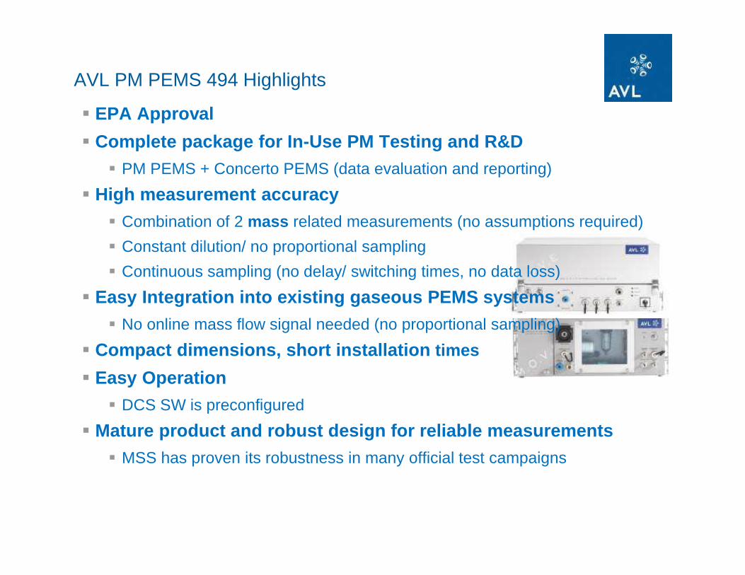
AVL PM PEMS 494 Highlights
� EPA Approval
� Complete package for In-Use PM Testing and R&D� PM PEMS + Concerto PEMS (data evaluation and reporting)
� High measurement accuracy� Combination of 2 mass related measurements (no assumptions required)
� Constant dilution/ no proportional sampling
� Continuous sampling (no delay/ switching times, no data loss)
� Easy Integration into existing gaseous PEMS systems� No online mass flow signal needed (no proportional sampling)
� Compact dimensions, short installation times
� Easy Operation� DCS SW is preconfigured
� Mature product and robust design for reliable measu rements� MSS has proven its robustness in many official test campaigns

HDIUT EXAMPLES – TRUCK

HDIUT EXAMPLES – OFF ROAD

HDIUT EXAMPLES – OFF ROAD
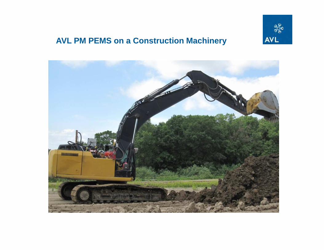
AVL PM PEMS on a Construction Machinery

AVL M.O.V.E GASEOUS EMISSION MEASUREMENT

AVL M.O.V.E GAS PEMS – Highlights
High Accuracy & Long Term Stability� “test cell grade” analyzers optimized for mobile use
(HFID, NDUV, NDIR)� analyzers are kept in temperature controlled enclosures� high measurement accuracy AND low drift for accurate measurements during long test durations
Robust against Temperature & Vibrations
� extended operating temperature range (-30°C to 45°C )
� dedicated heating circuit for condensate removal
� Internal and external damping provisions
Reduced Operating Costs and Easy Handling� NDUV sensor for parallel measurement of NO and NO2
� avoids need for ozonizer / converter� special provisions for minimized loss of NO2� internal calibration with gas filled cuvettes
� only FID fuel is needed as operating gas
� scheduled start-up procedure available
� short warm-up time
� hibernate mode

AVL Gas-PEMS - Climate Concept
tempered component
component with temporary cooling requirement
component with temperature stabilization
component with temperature stabilization
heater/cooler
inlet air fan with variable flow rate
component cooling fan with variable air flow rate (temperature depending)
outlet air fan with variable flow rate
flow restrictor
air conditioning compartment temperature sensor
ambient temperature depending conditioning air throttling
component cooling fan with defined air flow
internal heater
T-sensor
T-sensor
T-sensor
inlet and outlet air filter
AIR CONDITIONING COMPARTMENT
15.05.2013
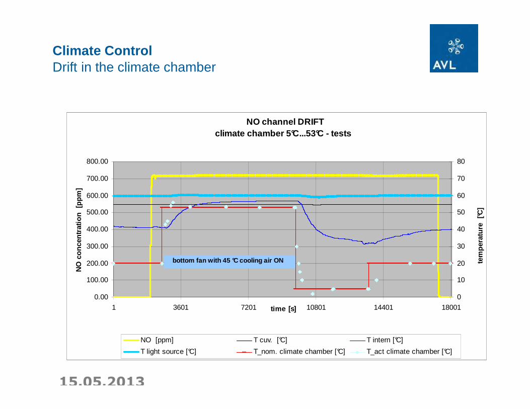
Climate ControlDrift in the climate chamber
NO channel DRIFT climate chamber 5°C...53°C - tests
0.00
100.00
200.00
300.00
400.00
500.00
600.00
700.00
800.00
1 3601 7201 10801 14401 18001time [s]
NO
con
cent
ratio
n [p
pm]
0
10
20
30
40
50
60
70
80
tem
pera
ture
[°C
]
NO [ppm] T cuv. [°C] T intern [°C]
T light source [°C] T_nom. climate chamber [°C] T_act climate chamber [°C]
bottom fan with 45 °C cooling air ON

AVL GAS PEMS System Overview
2 stage TE cooler to minimize NO2 losses and for ensuring H 2O removal for CO/CO 2 Measurement (~ 25°C inlet T NDUV/ ~ inlet T NDIR ~ 5°C )

AVL GAS PEMS Analyzer Specifications
Range Display Resolution
Accuracy Span Range Span Drift Zero Drift
CO 0 ppm …49999ppm
1 ppm 0 - 1000 ppm: +/- 30 ppm abs.1000 ppm - 10 vol%: +/- 3% rel.
0.1 vol% -8.2 vol%
≤ 20 ppm abs. / 8h or 2 % rel. / 8h
20 ppm / 8hrs.
CO2 0 - 20% 0.01 vol% 0 - 10 vol%: +/-0.2 vol% abs.10 - 16 vol%: +/- 2% rel.16 - 20 vol%: +/- 5% rel.
2 vol% - 20 vol% ≤ 0.1% abs / 8 hrs. abs. or 2% rel. / 8 hrs. rel.
0.1% / 8 hrs. abs.
NO 0 - 5000 ppm 0.1 ppm 0 - 400 ppm: +/- 10 ppm abs.400 - 5000 ppm: +/- 2.5 % rel.
500 ppm…5000 ppm
≤ 1% rel. / week 2 ppm abs. / 8 hrs.
NO2 0 - 2500 ppm 0.1 ppm 0 - 400 ppm: +/- 10 ppm abs.400 - 2500 ppm: +/- 2.5 % rel.
250 ppm…2500 ppm
≤ 1% rel. / week 2 ppm abs. / 8 hrs.
THC 0 – 30000 ppm C1
0.1 ppmC1 0 - 250 ppmC1: +/- 5 ppmC1 250 - 30000 ppm C1: +/- 2%
300 ppm…30000 ppm
≤ 1 % rel / 8 hrs < 1,5 ppmC1 abs. / 8 hrs
O2 0 – 25% 0,1 vol% ± 1 vol% of full scale at const. temperature and pressure
- -

AVL M.O.V.E GAS PEMS – Performance Verifications
Maintenance Testing
Linarization
required monthly (US EPA) or every 3 months (EU ISC)
… done manually at the moment
Request single bottles (up to 8): FID fuel, CO, CO2, C3H8, NO, NO2, N2, Synthetic Air (SL)
& Gas Devider Gas Bottle Requirements:
Linearization Gas Recommendation (based on AVL GAS-PEMS measuring ranges)
Calibration Gas recommendation Calibraion Gas Gas Quantiy for one typ.
low high Analysis Accuracy calibration linearization
C3H8 balance purified Synthetic Air [ppm] 9000 9800 1% 5l 30l
NO balance purified Nitrogen [ppm] 4500 4900 1% 5l 30l
NO2 balance purified Synthetic Air [ppm] 2250 2450 1% 10l 40l
CO balance purified Nitrogen [ppm] 45000 49000 1% 5l 30l
CO2 balance purified Nitrogen [vol%] 18 19,6 1% 5l 30l
additional required ZERO Gas: Synthetic Air and purified Nitrogen
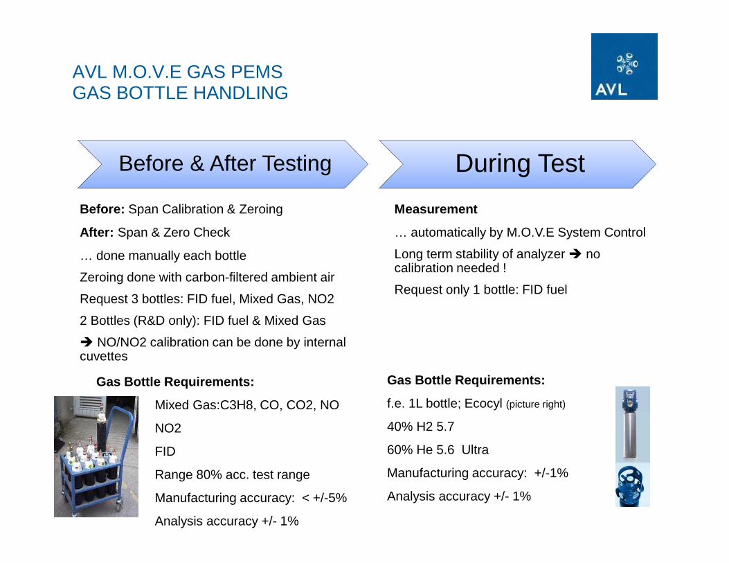
AVL M.O.V.E GAS PEMS GAS BOTTLE HANDLING
Before & After Testing During Test
Before: Span Calibration & Zeroing
After: Span & Zero Check
… done manually each bottle
Zeroing done with carbon-filtered ambient air
Request 3 bottles: FID fuel, Mixed Gas, NO2
2 Bottles (R&D only): FID fuel & Mixed Gas
� NO/NO2 calibration can be done by internalcuvettes
Gas Bottle Requirements:
Mixed Gas:C3H8, CO, CO2, NO
NO2
FID
Range 80% acc. test range
Manufacturing accuracy: < +/-5%
Analysis accuracy +/- 1%
Measurement
… automatically by M.O.V.E System Control
Long term stability of analyzer � nocalibration needed !
Request only 1 bottle: FID fuel
Gas Bottle Requirements:
f.e. 1L bottle; Ecocyl (picture right)
40% H2 5.7
60% He 5.6 Ultra
Manufacturing accuracy: +/-1%
Analysis accuracy +/- 1%

AVL M.O.V.E Mounting Solution heavy-duty and off-road

Batteries 2 x 12V
180-250VMains /
Generator
Charger24V/100A
E-Box:•Distribution•Fuses•Emergency-Stop
Emergency Stop
PM PEMS
GAS PEMS
System Control
StatusPanel
EFM
AVL M.O.V.E Power Supply


• Status Display to inform about state of charge / system status• E-Stop as additional safety measure in case of emergency• Supports any kind of Battieres (24VDC) or Generator Types (90-250VAC)
Power Supply
E-Box is the „heart“ of the power supply

Charger24V / 100A
230 V (180-250V)Grid Power / Generator
Main SwitchBattery
Batteries 2 x 12V115Ah
Shunt / Fuses / Distribution
Main SwitchCharger
Fuse 300A
PM
PE
MS
K
MA
mob
ile
Sys
tem
C.
Indi
Mic
ro
2 x 75mm² 2 x 75mm²
2 x 50mm²
3 x 2,5mm²
~= ==
In-Vehicle Power Supply im M.O.V.E Car (Seat Alhamb ra)

EXAMPLE BATTERIES – PASSENGER CAR

EXAMPLE GENERATOR – PASSENGER CAR
90- 250 V Grid Power
or Generator

EXAMPLE GENERATOR – HEAVY DUTY

HDIUT EXAMPLES – OFF ROAD

M.O.V.E Reference Projects
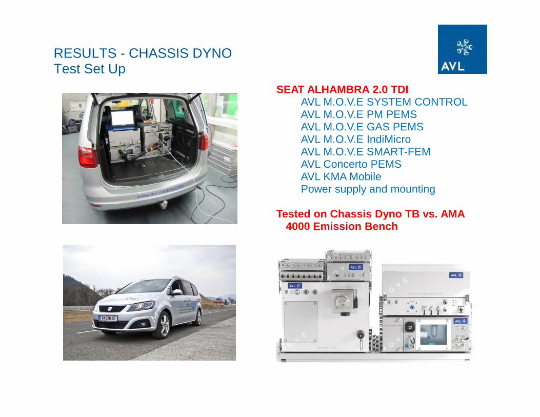
RESULTS - CHASSIS DYNOTest Set Up
SEAT ALHAMBRA 2.0 TDIAVL M.O.V.E SYSTEM CONTROLAVL M.O.V.E PM PEMSAVL M.O.V.E GAS PEMSAVL M.O.V.E IndiMicroAVL M.O.V.E SMART-FEMAVL Concerto PEMSAVL KMA MobilePower supply and mounting
Tested on Chassis Dyno TB vs. AMA 4000 Emission Bench
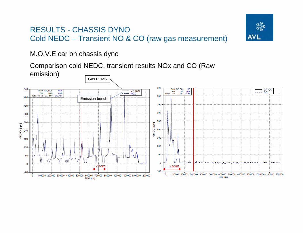
ZoomZoom
M.O.V.E car on chassis dyno
Comparison cold NEDC, transient results NOx and CO (Raw emission)
Gas PEMS
Emission bench
RESULTS - CHASSIS DYNOCold NEDC – Transient NO & CO (raw gas measurement)

ZoomZoom
M.O.V.E car on chassis dyno
Comparison cold NEDC, transient results NOx and CO (Raw emission)
RESULTS - CHASSIS DYNOCold NEDC – Transient NOx & CO (raw gas measurement)
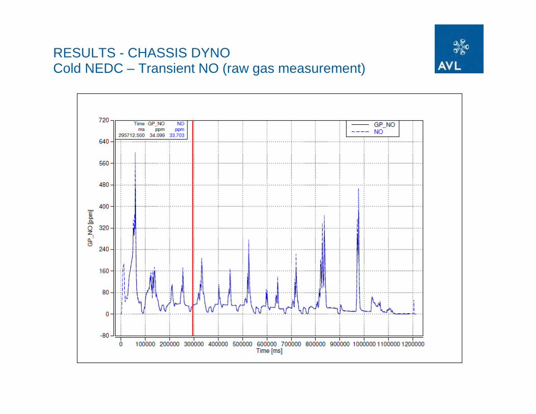
RESULTS - CHASSIS DYNOCold NEDC – Transient NO (raw gas measurement)

RESULTS - CHASSIS DYNOCold NEDC – Transient NO2 (raw gas measurement)
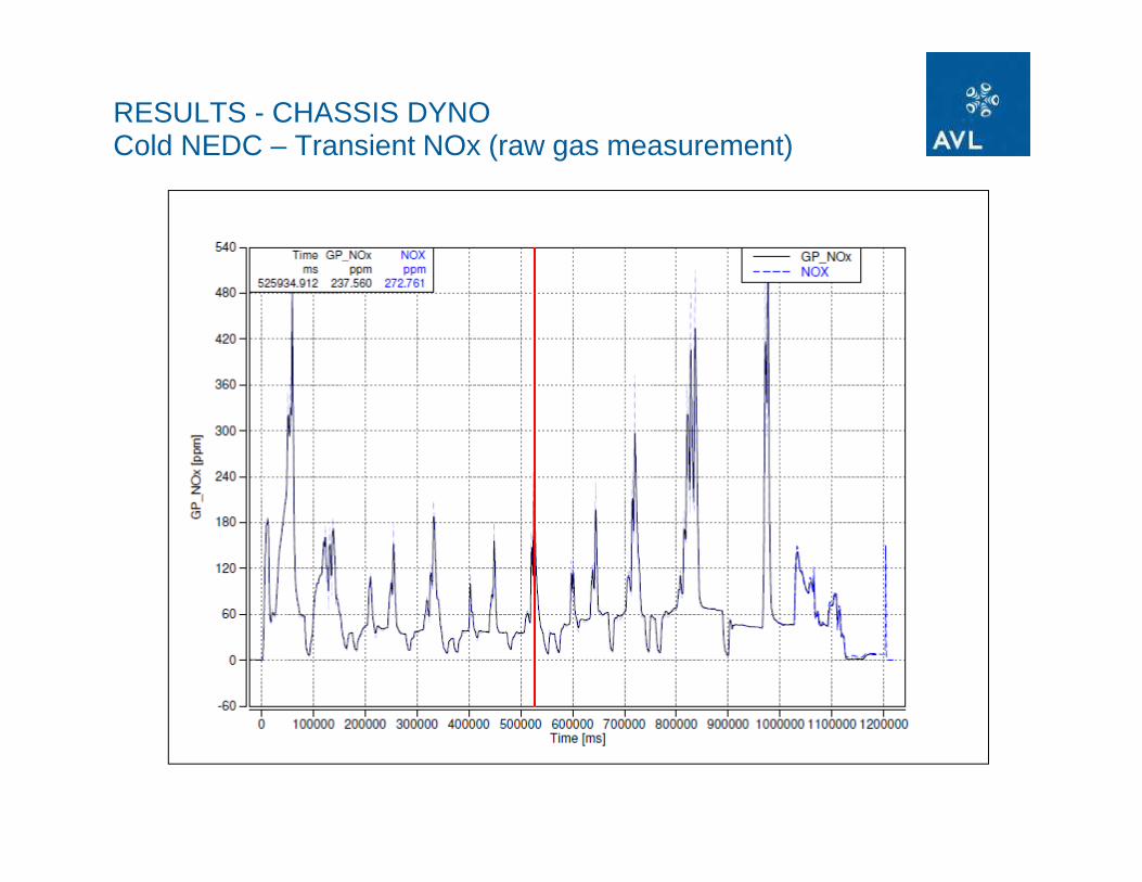
RESULTS - CHASSIS DYNOCold NEDC – Transient NOx (raw gas measurement)
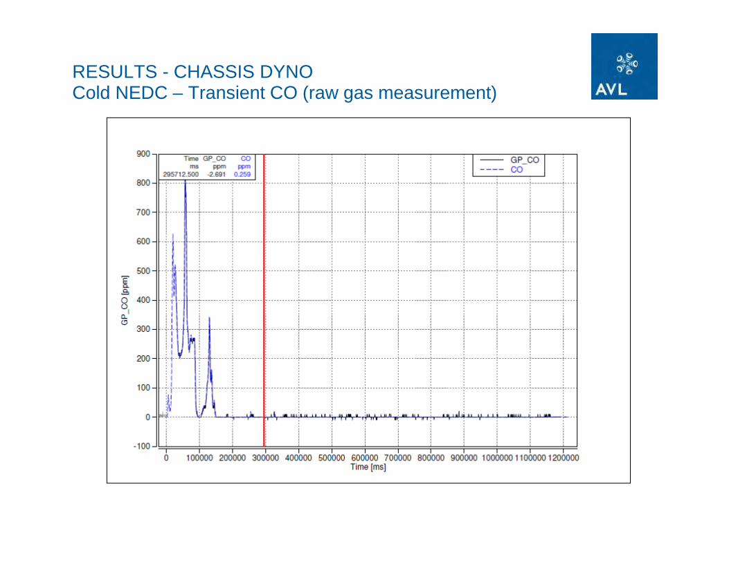
RESULTS - CHASSIS DYNOCold NEDC – Transient CO (raw gas measurement)
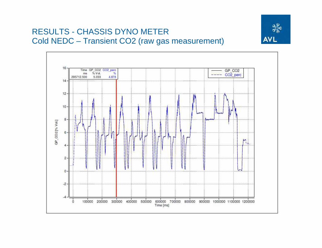
RESULTS - CHASSIS DYNO METERCold NEDC – Transient CO2 (raw gas measurement)
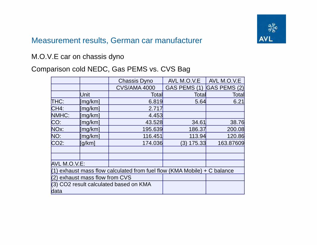
Chassis Dyno AVL M.O.V.E AVL M.O.V.ECVS/AMA 4000 GAS PEMS (1) GAS PEMS (2)
Unit Total Total TotalTHC: [mg/km] 6.819 5.64 6.21CH4: [mg/km] 2.717NMHC: [mg/km] 4.453CO: [mg/km] 43.528 34.61 38.76NOx: [mg/km] 195.639 186.37 200.08NO: [mg/km] 116.451 113.94 120.86CO2: [g/km] 174.036 (3) 175.33 163.87609
AVL M.O.V.E: (1) exhaust mass flow calculated from fuel flow (KMA Mobile) + C balance(2) exhaust mass flow from CVS(3) CO2 result calculated based on KMA data
Measurement results, German car manufacturer
M.O.V.E car on chassis dyno
Comparison cold NEDC, Gas PEMS vs. CVS Bag

� Test:
� Bag with constant concentration of gas components as input for Gas PEMS
� 2 rounds on shake test route with 20 km/h (moderate to severe shocks)
� Curve driving
� How does this effect measurement robustness???
� Results:
� Total system without problems
� Gas PEMS – NO concentration: Effects of vibration (in the range of few ppm)
Measurement results, German car manufacturer
M.O.V.E Car on shake testing route

OFF-ROAD TestingTractor Fendt
• PM PEMS • Gas PEMS
Setup consisting of
• System Control• Sensors EFM
• Generator• Battery pack
• E-Box• Rugged cases

OFF-ROAD Testing
Test: Plowing (Full Load)
Test: Towing 13t Trailer (Partial & Full Load)

OFF-ROAD TestingResults Cutting
MARKET DRIVER – FUEL ECONOMY
deviation between ECE- and real-world fuel consumption
Up to
Source: TheAuto-Motor- & Sport Fuel Consumption Circuit

Mobile Fuel Consumption Measurement User Requirements
In-Vehicle Fuel consumption Measurement
• Momentary flow rate and total consumption measurement
• Display to driver as well as data logging
• High accuracy and reproducibility under real road condition
• Easy handling and installation
• No influence on vehicle / engine performance
• Compatibility with all vehicles and fuels

Data Logging
Fuel Consumption Measurement
Wheel Speed Measurement
Track / Speed Measurement
DataAnalysisApplications:
Benchmark
Fuel Economy Verification
Reliability / Complaint
Mileage Accumulation
etc.
In-Vehicle Fuel Consumption Measurement Stand-Alone Customer Requirement

Data LoggingFuel
Consumption Measurement
Wheel Speed Measurement
Track / Speed Measurement
Data Analysis
In-Vehicle Fuel Consumption Measurement Stand-Alone System Solution
GPS sensor• USB interface • GPS-sensor supplier
Garmin• 12V supply required
Optical reflection sensor• Analog output • Sensor supplier tbd• 12V supply required
KMA Mobile ����M.O.V.E Fuel• Analog output• Alternative:
frequency output
• 12V supply required
MOVE System Control SW BASIC • Functionality
reduced to basic data logging
• Hardlock protected• USB interfaces• 12V power supply
M.O.V.E System Control xTension Box• USB interface• Analog inputs• 12V power supply
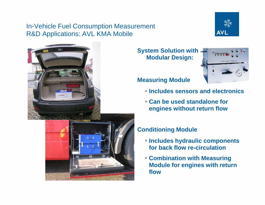
In-Vehicle Fuel Consumption Measurement R&D Applications: AVL KMA Mobile
System Solution withModular Design:
Measuring Module
� Includes sensors and electronics
� Can be used standalone for engines without return flow
Conditioning Module
� Includes hydraulic components for back flow re-circulation
� Combination with Measuring Module for engines with return flow

In-Vehicle Fuel Consumption Measurement Mileage Accumulation: AVL PLU116H
Sensor Solution for Customer Integration:
PLU116H Fuel Flow Sensor
� Includes sensors and electronics
� Can be used standalone for engines without return flow
Self-Installation Kit
� Includes hydraulic components for back flow re-circulation
� Combination with PLU116H Flow Meter for engines with return flow
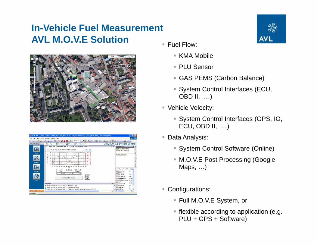
In-Vehicle Fuel Measurement AVL M.O.V.E Solution
� Fuel Flow:
� KMA Mobile
� PLU Sensor
� GAS PEMS (Carbon Balance)
� System Control Interfaces (ECU, OBD II, …)
� Vehicle Velocity:
� System Control Interfaces (GPS, IO, ECU, OBD II, …)
� Data Analysis:
� System Control Software (Online)
� M.O.V.E Post Processing (Google Maps, …)
� Configurations:
� Full M.O.V.E System, or
� flexible according to application (e.g. PLU + GPS + Software)

M.O.V.E Fuel Measurement Online & Trip Results
� Online Display of:
� GPS Position
� GPS Altitude
� Velocity
� actual l/100km
� actual mpg
� km/miles driven
� Trip results:
� km/miles driven
� total fuel (l or g) used
� average l/100km
� average mpg

AVL M.O.V.E Data LoggerIntegrative Mobile Vehicle Evaluation
INTEGRATION IS KEY
� quick extension to your on board
fuel system
� provides online result by l/km
� extends your usability
� extendable to further applications
like Emission (PEMS) testing
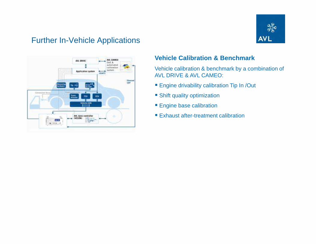
Further In-Vehicle Applications
Vehicle Calibration & Benchmark
Vehicle calibration & benchmark by a combination of AVL DRIVE & AVL CAMEO:
� Engine drivability calibration Tip In /Out
� Shift quality optimization
� Engine base calibration
� Exhaust after-treatment calibration
FUEL
CONSUMPTION
AVL M.O.V.E APPROACH - INTEGRATION IS KEY
Results
GASEOUS
EMISSION
INTEGRATION
APPLICATION
PM
EMISSION
EXHAUST
MASS FLOW
GPS
AMBIENT
TEMPERATURE
PRESSURE
MEASURE
VEHICLE CAN
CONTROL UNITS
COMBUSTION
DATA POST PROCESSINGDATA REDUCTION
DRIVE
M.O.V.E and Drive for
Advanced Drivability Calibration

Integration ofEmissions,
Fuel Consumption, Indicating and
Drive is available!
AVL M.O.V.E & DRIVE Application

Further In-Vehicle Applications
AVL Real Life Testing or Road to Lab to Math
Recorded vehicle data are transferred from the road (“real life”) to the test bed and to simulation
� Unified testing throughout the entire development process
� Achieve best results for maneuver-based testing
� Verify and improve the quality of simulation
Vehicle Calibration & Benchmark
Vehicle calibration & benchmark by a combination of AVL DRIVE & AVL CAMEO:
� Engine drivability calibration Tip In /Out
� Shift quality optimization
� Engine base calibration
� Exhaust after-treatment calibration

Real-Life-Measurements at the Test Bed
Test Bed
real maneuvers
real measurementssimulated reality
Exact repeatability of maneuvers
AVL InMotion AVL M.O.V.E

Target of AVL Real Life Testing: Consistency
Data:
� Measurement principles
� Device parameterization
� Data format
Methodologies:
� Test
� Simulation
� Integration of Real Life data into Simulation
Simulation
Road
Test Bed
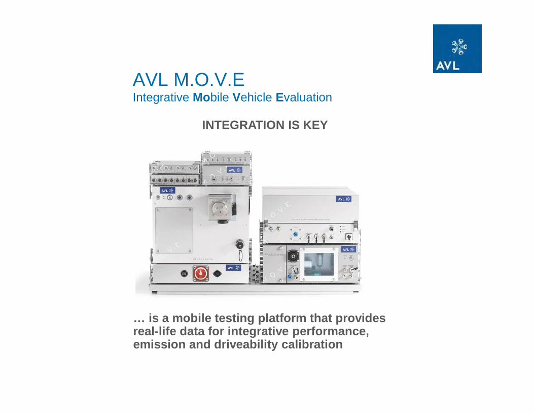
AVL M.O.V.E Integrative Mobile Vehicle Evaluation
… is a mobile testing platform that provides real-life data for integrative performance, emission and driveability calibration
INTEGRATION IS KEY

Exhaust Flow DeterminationThe US EPA has defined the following 3 Methods:
Method 1: "direct measurement fo exhaust flow using a flow meter"DEVICE Channels Required RemarkECU NONEKMA MOBILE NONEEFM Exhaust Volume Flow
Exhaust TemperatureExhaust Pressure
Method 3: Option 1: calculate exhaust flow using fuel flow from ECUDEVICE Channels Required RemarkECU Engine Fuel RateKMA MOBILE NONEGAS PEMS CO2
CO negligible contribution for typical diesel engine
THC negligible contribution for typical diesel engine
Method 3: Option 2: calculate exhaust flow using fuel flow from KMA MobileDEVICE Channels Required RemarkECU NONEKMA MOBILE Engine Fuel RateGAS PEMS CO2
CO negligible contribution for typical diesel engine
THC negligible contribution for typical diesel engine
Method 2: Combination of Method 1+3

Boost Pressure
Barometric Pressure
Engine Speed
Engine Torque
Percent Friction Torque
Percent Actual Torque
Engine Load
Fuel Rate
Vehicle Veloctiy/Speed
Intake Manifold Temperature
Engine Air Inlet Pressure
Oil Pressure
Oil Temperature
Throttle Position
Recommended