Coordination and protection of busbar distributionLow voltage expert guides n° 1
Technical collection

������������� ��������������������
�����������

�
Content
Busbar distribution system 3�.�. Performance criteria of a LV Busbar distribution 3�.2. Functions 6
Level A: transmission and distribution with a small quantity of tap points 6Level B: distribution with a large quantity of tap points 6Level C : the final distribution 7
�.3. IEC 60439.2 standard 8�.4. BBT protection 9
Overload protection 9Short-circuit protection by circuit breaker ��Circuit breaker/busbar trunking coordination ��
�.5. Busbar distribution coordination �4�.6. Summarizing busbar distribution characteristics �4
The Schneider Electic busbar distribution System 152.�. BBT/circuit breaker coordination �8
Protection of a transmission or distribution BBT downstream from the Main Switchboard (MSB) �8Protection of an BBT by an NSX400N limiting circuit breaker �8
2.2. Exclusive features of the Schneider Electric system: enhanced busbar distribution coordination 202.3. Final distribution 2�2.4. Advantages of the Schneider Electric system 22
BBT protection 22Tap off boxes 22Final distribution 23
2.5. Advantages and exclusive features of the Schneider Electric system 23Comprehensive coordination choice guide tables 23Standard performance circuit breakers for all Isc y 70 kA 23Optimization of the tap off box offer 23Summarizing table 24

2

3
Busbar distribution
Design and production of a busbar distribution installation for industrial and commercial buildings must meet 3 main requirements: progressive upgradeability of the installation, simplicity and dependability. Busbar distribution ensures these requirements are fully met.
1.1. Performance criteria of a LV Busbar distribution
Three performance criteria for a busbar distribution installation:
upgradeabilitysimplicitydependability
bbb
1. Progressive upgradeability of the installation“Flexibility” and “Adaptability” have become the key words in all commercial and industrial activities which need to quickly adapt to the market in order to:
meet their customers’ needs,cope with rapid changes and fluctuations in demand.
These performance criteria are expressed in terms of:quantity of goods to be produced or of services to be provided....continually decreasing manufacturing lead time,quality: the level of quality of the products and associated services must be
equivalent whatever the decisive parameters (short lead time, large quantity to be produced,...).
This implies permanent adaptation of production means as production rates are stepped up after initial commissioning, and the process is completed by new machines.
Busbar distribution, with its highly flexible design, fully covers these requirements.
2. Simplicity of the busbar distributionEasy to design: the study is feasible regardless of energy distribution and load
layout. Choice of equipment is predetermined and optimized.Easy to install thanks to the factory-built concept.
3. DependabilityDependable electrical distribution is optimized as a means of guaranteeing:
safety of persons and equipmentcontinuity of service (choice of grounding system, implementation of
discrimination techniques, breaking not required when making changes to the installation....)
reliability (reliable switchgear, factory-mounted subassemblies...)easy maintenance (simple, rapid modifications).
Dependability also guarantees an economic operating solution.
Busbar distribution fully meets these criteria.
bb
bbb
b
b
bb
bb

4
Busbar distribution
Distribution is divided up into 3 separate levels between the transformer and the final applications:
level A: Transmission and distribution with a small quantity of tap points,
level B: Distribution with a large quantity of tap points
level C: the final distribution.
Busbar Trunking (BBT) distribution fully covers the requirements of each level by providing:
functions that are often specific in nature;
a high degree of operating reliability in compliance with the IEC 439-2 standard.
b
b
b
b
b
In large sites Buildings in excess of 5 000 m²
The following diagrams represent standard installations which cover most cases encountered in practice.
DB
�253
36
y 400 A
y 160 A15 to 25 kAy 400 A
i 800 A
y 40 Ay 5 to10 kA
y 40/63 A y 10 to 16 kA
y 25 A(40 A)
Isc 10 to15 kA
y 400 A
100 to 250 A
MMM
Isc 20 to 50 kA
Isc 10 to 40 kA
20 to 70 kA
Isc 20 to 70 kA
Isc 30 to 80 kA
with a smallquantity oftap points
T1 transmission
MSB
workshop 2 supplyworkwhop 1supply
1000 to 5000 A
TØ transmission
large manufacturing processindustry
manufacturing process moving tool(maintenance, servicing)
lighting
automationenclosure
use
automationenclosure
socketenclosure lighting
NB. right next to the machine orbuilt into the machine
hall 1supply
hall 2supply
hall 3supply
bay 2supply
distributionwith a largequantity of tappoints bay 1
supply
5
Busbar distribution
In medium-sized and small sites Buildings smaller than 5 000 m²
DB
�253
37 Level ATransmission and distribution with a small quantity of tap points.Note : does not concern “medium-sized and small sites“.
400 A
30 mA
warehouse storage
10 kA
ID63 s60 A
PC
100 to 250 A
25 to 40 A
M
< 63 A
lighting
homogeneous load,offices
final distribution purpose of building
10 to 15 kA
10 to 15 kA
y 5 kA
15 kA
Level BDistribution with a large quantity of tap points.
Level CEnergy utilisation.

6
Busbar distribution
1.2. Functions
BBT in transmission and distribution with a small quantity of tap points
High current ratings from 1000 A to 5000 A
High short-circuit withstand up to 150 kA
Technological continuityFlexibility
BBT in Distribution with a large quantity of tap points:
numerous tap off socketsbox positioning flexibilitysafe, easy handling
Final distribution:on-load opening (emergency breaking)local disconnection.
b
b
bb
bbb
bb
Level A: transmission and distribution with a small quantity of tap points
RequirementsThis level corresponds to Transformer/Main Switchboard (MSB) supply and main distribution downstream from the Main Switchboard (MSB).The requirements of this level as far as performance criteria are concerned (see p. 3) are summarized in the table below:
Performance criteria Requirement Comments
Upgradeability b b modifications at this level of the installation although rare are important; new layouts do not affect main distribution
Simplicity b b b Power is available at all points of the installation as from the design stage.Implementation simplified by the factory-built BBT concept.
Dependabilitycontinuity of service b b b b Distribution is entirely placed
downstream. Maintenance is performed with power on.
safetyb b b Safety of persons must be guaranteed.Maintenance is rare and is carried out by qualified staff. A high degree of reliability in the event of an electrical fault is required.
b minor requirement b b average requirement b b b major requirement
Busbar Trunking (BBT) with a small quantity of tap points for transmission and distributionThe T0 busbar trunkings convey energy from the MV/LV transformer directly to the Main Switchboard (MSB). The T� busbar trunkings, downstream from the Main Switchboard (MSB), convey and distribute energy to BBTs with a large quantity of tap points which supply the various workshops. Use transmission and distribution BBTs with a small quantity of tap points ensures a simple, suitable solution:
the characteristics of the transmission BBTs authorize current ratings ranging from �000 A to 5000 A and short-circuit withstand levels up to �50 kA.
use of a flexible link to level B BBTs ensures technological continuity and flexibility of the installation.
BBTs have a small quantity of tap points, as the number of feeders to be supplied (workshops, halls) is small.
tap off boxes are of the power on fixed or withdrawable type.
b
b
b
b
Level B: distribution with a large quantity of tap points
RequirementsTwo types of loads must be supplied downstream from the distribution BBTs:
workshops and large machines (automation cubicle). In this case the short-circuit and current levels may still be high (20 to 70 kA respectively and up to 800 A) (see large sites on page 4).
bays and small machines (switchboard, automation enclosure, lighting circuit...). Short-circuit and power levels are lower, �0 to 40 kA respectively and up to 400 A.
b
b
7
Busbar distribution
Performance criteria are summarized in the table below.
Performance criteria Requirement Comments
Upgradeability b b b Major modifications are possible. The tap off points (loads) evolve physically and electrically, thus calling for: – distribution with high density tap off sockets, – upgradeability without interrruption of service continuity.
Simplicity b b b On design and installation.It must be possible to place the tap off boxes anywhere on the busbar trunking whatever the Isc level.
Dependabilitycontinuity of serviceb b b b Modifications are made without
breaking.The tap off boxes can be connected and disconnected with power on.
safetyb b b b Modifications made with power on must be �00% safe:– direct contact protection– polarization for proper installation of the tap off boxes– performances of the tap off box equipped with its circuit breaker automatically compatible with the Isc at the considered point.
b minor requirement b b average requirement b b b major requirement
Busbar Trunking (BBT) with a large quantity of tap points for distributionBBT distribution meets the operator’s needs:
a large quantity of tap off sockets�00% safe connection of tap off boxes with power onboxes can be placed anywhere on the BBTeasy, fully safe disassembling/reassembling/addition of tap off boxesprotection device placed near to the user, thereby ensuring easy handling.
Busbar Trunkings comply with the IEC 439-2 standard (see page 9) which guarantees their quality and reliability whatever changes are made to the installation.
bbbbb
Level C : the final distribution
RequirementsDownstream final distribution is often linked to the load. The performance criteria requirements are:
Performance criteria Requirement Comments
Upgradeability b b b The BBT tap off boxes must be standard. Protection devices must have a wide setting range.Simplicity b b
Dependabilitycontinuity of service b b b b
It is vital that protection of the load(s) in the automation cubicle be fully coordinated with the upstream protection devices.
safetyb b b b Of persons and equipment.
b minor requirement b b average requirement b b b major requirement

8
Busbar distribution
The final distributionIt must meet a number of characteristics in order to ensure system performance, in particular as concerns continuity of service and safety. On-load opening, necessary for emergency breaking, and disconnection are requirements to be built into the enclosure incoming switch. Moreover, the control and protection switchgear are easily accessible to the user, thus making them easy to handle.
DB
�253
38
connectingcable
BBT
tap offcircuit breaker
isolatingswitch
industrialcontrolcircuit breaker
automationcubicle
DB
�253
39
connectingcable
BBT
tap offcircuit breaker
isolatingswitch
final distributioncircuit breaker
final distributionenclosure
1.3. IEC 60439.2 standardIEC 60439-1
LV switchgear assemblies
IEC 60439-2
Second part : specific busbar trunking rules.
General
Area of application: busbar trunkings for power and lighting distribution.
Factory quality
Manufacturer’s guarantee characterizing the product.
Product quality and dependability guaranteed by a series of factory tests.
This standard concerns LV switchgear assemblies.
Busbar trunkings must comply with the rules laid down in publications 60439-1 and 2.
DéfinitionsBusbar trunking:Switchgear type tested assembly in the form of a conductive network concerning, in a duct, cableway or similar enclosure, busbars which are supported by insulating materials.This assembly can be made up of:
busbar parts with or without tap off points,power supply, flexible links,branch busbar parts.
Electrical characteritics of the assembliesThe manufacturer must specify the mean values for the various phases:R: mean ohmic resistance of the busbar trunking per meterX: mean reactance of the busbar trunking per meterZf: impedance per meter of loop length, including the protection circuit (PE) and the phase giving the highest impedance.Indirect contact protection by automatic power supply breaking using over current protection devices.
bbb

9
Busbar distribution
Construction arrangementsBusbar trunkings must be designed as type tested LV switchgear assemblies (TTA).According to the manufacturer’s instructions, BBTs are designed to withstand mechanical loads.For safety reasons, an BBT equipped with tap off points must be designed in such a way as to prevent incorrect connection of the tap off parts.If three-phase ac is used, phase order must be constant throughout the BBT. Temperature rise limits are defined on the enclosures and connection terminals.
Test specificationsType tests are designed to check compliance with the specifications laid down for a given BBT type.Type tests are carried out on a copy of an BBT or on an BBT type produced using the same or similar drawings.Type tests consist of:
checking temperature rise limits, dielectric properties, short-circuit withstand, electrical continuity of the protection circuit, clearances and creepage distances, mechanical operation, degree of protection, resistance, reactance and impedance, and sturdiness of the construction.The standard describes all the conditions and provisions of the tests laid down and, if necessary, the results to be obtained.
b
1.4. BBT protection
A 20% shift of the opening currents results in a minimum overcalibration of 10% of the busbar trunking if fuse protection is used.
This must be provided in accordance with installation standards.
Overload protection
The busbar trunking supplies loads: the total load current is lr.
Sizing characteristics for choice of BBT and overload protection are:current rating lb = k� x IT (k� is the concentrationfactor)rated busbar trunking current lnc > lbpermissible current as a function of temperature lz = f� x lnc
(f� is the temperature factor)derating factor k2 linked to the type of switchgear: fuse k2 = 1.1circuit breaker k2 = 1
For extension purposes, busbar trunking is normally protected for its rated current lnc (or for their permissible current lz if the temperature factor f� is applied).
In order to take account of busbar trunking thermal overload protection, the various protection switchgear technologies and the maximum opening currents for protection devices in overload conditions must be considered.
Calibration of thermal asymptotes:the distribution fuse is calibrated to trip on overloads of between �.25 and �.6
times its rated curent (fuse ln)the circuit breaker is calibrated to trip on overloads of between �.05 and �.3
(�.2 for circuit breakers with electronic protection) times its setting current (lr as a function of circuit breaker ln)
Maximum opening current:this current is set at most by the installation standards (IEC 60364,
NFC �5-�00,...) to �.45 times the current permissible to the busbar trunking.
bbb
bvv
bv
v
bv
DB
�253
40
InIz = 1.1 InIz = Inc if fz = 1
I
1.25 to 1.6 In
1.45 Iz
t(s)
Fuse.
DB
�253
40
InIz = 1.1 InIz = Inc if fz = 1
I
1.25 to 1.6 In
1.45 Iz
t(s)
Fuse.
DB
�253
4�
I
t(s) 1.05 to 1.3 In
In
Iz = In
1000
1.45 IzCircuit breaker.
DB
�253
4�
I
t(s) 1.05 to 1.3 In
In
Iz = In
1000
1.45 IzCircuit breaker.

�0
Busbar distribution
Example for a current lb = 400 A in an ambient temperature of 35°C:fuse protection:
lnc = lb x f1 x k2 = 400 x 1 x 1.1 = 440 AThe busbar trunking chosen is KSA50 (lnc = 500 A)
circuit breaker protection: lnc = lb x f1 x k2 = 400 x 1 x 1 = 440 AThe busbar trunking chosen is KSA40 (lnc = 400 A)
v
v
If operating conditions are different from rated conditions of use, the circuit breaker offers enhanced optimization of busbar trunking protection (e.g. operation at high ambient temperatures of 45°/50 °C).
Setting circuit breakers equipped with electronic trip units:
thermal protection lr adjustable from 0.4 ln to ln
short-circuit protection from 2 lr to 10 lrincreased flexibility and upgradeability.
b
bb
Fineness of the thermal settingThe fuse is given a fixed rating. Current changes in the device to be protected
require fuse replacement.The difference between 2 fuse ratings is approximately 25 %. Standard ratings are given according to the series of characteristic numbers of the “Renard” series.For example: 40 - 50 - 63 - 80 - �00 - �25 - �60 - 200 - etc.
The circuit breaker offers a setting fineness of:5 % for circuit breakers equipped with conventional thermal-magnetic trip units,3 % for circuit breakers equipped with electronic trip units.
For example: a circuit breaker with a nominal rating of �00 A can easily be set to values of lr = �00 A, 95 A, 90 A, 85 A, 80 A.For example: a circuit breaker with a nominal rating of �00 A set at 90 A will be used to protect a KSA�0 busbar trunking (lnc = �00 A) which is used for an ambient temperature of 50°C (see table of maximum permissible temperatures as a function of operating temperature).
Extensive setting range of circuit breakers equipped with electronic trip unitsCircuit breakers equipped with electronic trip units or setting dynamics in:
thermal protection lr adjustable from 0.4 ln to lnshort-circuit protection from 2 lr to �0 lr
For example: a 250 A circuit breaker (NSX250N equipped with a Micrologic 2.2) can easily be set in:
thermal protection of �00 to 250 Ashort-circuit protection of 200 to 2500 A
DB
�25�
65
Exemple of setting possibilities.
This ensures a high degree of flexibility with respect to:modifications (flexibility), extensions (upgradeability): protection devices are
easily adapted to the application requiring protection and to the grounding system used (protection of persons and equipment)
maintenance: use of this type of device considerably reduces maintenance component stocks.
b
bvv
bb
bb
b
b

��
Busbar distribution
Short-circuit protection by circuit breakerBBT sizing is determined by 3 types of characteristics:
the maximum peak current, peak lthe maximum short-term rms current, lcwthe thermal stress (in A2s).
bbb
Inherent BBT characteristiquesBBT short-circuit sizing is determined by the following characteristics:■ the maximum peak current, peak l:this characteristic expresses the instantaneous electrodynamic withstand limits of the busbar trunking. Peak current value is often the most restrictive instantaneous characteristic for the protection device.■ maximum short-term rms current lcw:this characteristic expresses the permissible temperature rise limit of conductors for a given period of time (0.� to � s).■ the thermal stress in A2s:this characteristic expresses the instantaneous thermal stress withstand of the BBT. Normally, if the short-circuit generates fault conditions that are compatible with the first two characteristics, this constraint is “naturally satisfied”.The assumed short-circuit current to be considered for BBT protection is the one found at supply box level.
Circuit breaker characteristicsCircuit breaker D must meet the requirements of product construction standards (IEC 60947-2,...) and installation standards (IEC 60364 or relevant country standards), i.e. its breaking capacity lcu(1) must be greater than short-circuit current Isc at the point where it is installed.(1) installation standard IEC 364 and the construction standards specify that the breaking capacity of a circuit breaker is:■ the ultimate breaking capacity, lcu, if it is not coordinated with an upstream protection device■ the breaking capacity enhanced by cascading, if there is coordination with the upstream protection device.
Applications■ Two cases must be considered :
directely protected busbar trunkingcircuit breaker lcu u assumed Isc at point ABBT peak l u asymmetrical assumed or limited Isc at point ABBT thermal withstand in lcw u thermal stress passing through the BBT
busbar trunking protected downstream from a cablecircuit breaker lcu u assumed Isc at point ABBT peak l u asymmetrical assumed or limited Isc at point BBBT thermal withstand in lcw u thermal stress passing through the BBT.
v
v
Circuit breaker/busbar trunking coordination
This coordination depends on the type of circuit breaker protecting the busbar trunking.
Non-limiting or time-delayed circuit breakerThese are non-limiting (instantaneous or time-delayed) circuit breakers and time-delayed limiting circuit breakers, mainly of the air power (> 800 A) type.The busbar trunking must be able to withstand the fault peak current to which it may be submitted as well as thermal withstand during any time delay:
the permissible peak current, peak l, of the BBT must be greater than the peak value of the assumed asymmetrical short-circuit current, asymm. Isc, at point A.The value of the asymmetrical short-circuit current is obtained from the value of the symmetrical short-circuit current, Isc, multiplied by a standardized asymmetry factor (k).The first value of the 1st short-circuit asymmetry peak in the transient state is the one that is taken into account.
b
DB
�253
44
busbar trunkingIcw (u T)T = 1s
Isc
I1
busbar trunkingpeak I
T
t
asymm Isc
Current value of the 1st peak as a functon of rms Isc.
DB
�253
44
busbar trunkingIcw (u T)T = 1s
Isc
I1
busbar trunkingpeak I
T
t
asymm Isc
Current value of the 1st peak as a functon of rms Isc.

�2
Busbar distribution
Standardized table for calculating the asymmetrical short-circuitIsc: assumed symmetrical short-circuit kA (rms value)
Assymetric factor k
4.5 y I y 6 �.56 < I y �0 �.7�0 < I y 20 2.020 < I y 50 2.�50 < I 2.2
For example: for a circuit with a assumed short-circuit current of 50 kA rms, the first peak reaches 105 kA (50 kA x 2.1): see figure opposite.
The short-term short-circuit current, lcw, of the BBT, must be greater than the current flowing through the installation for the duration of the short-circuit Isc (duration T - total breaking time - including the time delay if any -).For example: a KTA�6 BBT has an lcw characteristic of 60 kA for T = � second, i.e. a thermal stress withstand expressed in A2s equal to 3.6x�09 A2s.
If one of these relationships is not verified, a suitable higher rating must be chosen for the BBT.
Limiting circuit breaker This mainly concerns protection of BBTs by moulded case type circuit-breakers (u �250 A).In this case it is ensured that the BBT withstands the peak current limited by the protection device and the corresponding thermal stress.
The current limited (peak l) by the circuit-breaker is y the peak current permissible to the BBT.
The thermal stress limited by the circuit-breaker is y the thermal stress permissible to the BBT.
Cheking BBT withstand in peak I
DB
�253
46
Icc
Ipeak (kA)
assumed short-circuitcurrent
peak currentlimited in thebusbar trunking
Ipeak
IL current limitationcurve
Iscnon-limitingpeak current
maximum currentpermissible to thebusbar trunking
Checking BBT withstand in A2S
DB
�253
47
Icc
A2s
assumed short-circuitcurrent
thermal stresspermissible to thebusbar
thermal stresslimitation curvethermal stress
limited in thebusbar trunking
If either of these conditions is not met, oversizing of the BBT will be required.
b
b
b
DB
�253
45
250
200
150
100
50
04,5 6 10 20
rms Isc
Ipeak (kA)
50 100
105 kA
Transcient and steady states of a short-term short-circuit.
DB
�253
45
250
200
150
100
50
04,5 6 10 20
rms Isc
Ipeak (kA)
50 100
105 kA
Transcient and steady states of a short-term short-circuit.

�3
Busbar distribution
BBT protection summarizing tableNetwork characteristics
IscCircuit breaker characteristics / Short-circuit constraints
Icu u Isc at point ABBT characteristics / Short-circuit constraints (1)
Peak I Icw for T (3) A2sBBT withstand Permissible Instantaneousat peak current short-term current thermal withstandk kA rms x f(T) kA2s
Time-delayed non-limiting circuit breaker
Peak I u Isc x k (2) Icw u Isc
Limiting circuit breaker Peak I u IL limitedby the circuit breaker
kA2s (BBT) u kA2s limitedby the circuit breaker
Characteristics that are not applicable or that are naturally verified(1) the Isc of the network under consideration is that at the BBT connection point (at point A)(2) asymmetry factor (see page 13)(3) T: total breaking time including any time delays.
DB
�253
42
BBT
circuit breaker
A
Isc at point A
DB
�253
43
B
circuit breaker
cab le
BBT
A'
The busbar trunking short-circuit protection level can be either total or partial:total protection: the busbar trunking is protected up to the ultimate breaking
capacity of the circuit breakerpartial protection: the busbar trunking is protected up to a high short-circuit
current level (e.g. 55 kA) but less than circuit breaker ultimate breaking capacity (lcu) (e.g. lcu = 70 kA).
DB
�253
48
Isc
BBT2protectionlimit
partialprotection
BBT 1
circuit breakercurve
total protection
BBT 2
I (12 kA) Icu (25 kA)
Ipeak (Â)
DB
�253
49
Isc(150 kA)
Ipeak (Â)
BBT2protectionlimit
partialprotection
BBT 1
limitingcircuit breakercurve
total protection
BBT 2
I (25 kA) Icu
Non-limiting circuit breaker. Limiting circuit breaker.
bv
v
�4
Busbar distribution
1.5. Busbar distribution coordination
Protection device coordination:
System performance is guaranteed by standardization of circuit breaker protection and BBT busbar distribution.
The performance of a busbar distribution system depends on the specific characteristics of each of its component parts.
This performance will be optimized by providing proper coordination, obtained by a system type design.
Continuity ofservice and discriminationThe previous chapters dealt with BBT overload and short-circuit protection.An installation is always made up of a number of distribution levels.Continuity of service must be guaranteed by ascending coordination of protection devices from the load to the source. This coordination relies on discrimination techniques.Discrimination of protection devices consists of coordinating automatic protection devices so that a fault occurring at any point of the network is eliminated by the circuit breaker immediately upstream from it and by this circuit breaker alone.The performance of an electrical distribution system is guaranteed by standardization of circuit breaker protection and BBT busbar distribution.
1.6. Summarizing busbar distribution characteristics
The performance criteria of a distributed electrical distribution installation in industrial and commercial buildings call for functions whose characteristics are summarized in the table below.
Criteria Relevant functions
Level A transmission and distribution with a small quantity of tap points
Level Bdistribution with a large quantity of tap points
Level Cfinal distribution
Upgradeability numerous tap off points v b
Simplicity easy study and installation b b v
easy site modification v b v
Continuity of service discrimination of protection devices b b b
modification with power on v b
protection device easily reset v v b
Safety controlled fault parameters (1) b b b
on-load braeking and disconnection b b b
vital maximum performancenormal performance
(1) System global control - Circuit breaker protection device coordination - Inherent BBT performance - Protection of persons and equipment - Compliance with standards - etc...
bv

�5
The Schneider Electic busbar distribution System
Busbar distribution fully satisfies requirements for upgradeability, simplicity, continuity of service and safety.Schneider Electric recommends a System type approach to perform the above functions.These solutions are based on a BBT busbar distribution system, protected by circuit breakers, and provide:
simplicity of choicehomogeneity of solutionsrationalization of componentsa manufacturer’s guarantee of System coordination.
The two block diagrams on the following pages give some examples of the Schneider Electric circuit breaker protected busbar distribution system.
bbbb

�6
The Schneider Electic busbar distribution System
In large sites Buildings in excess of 5 000 m²
DB
�25�
74
Level A
Level B
Level C
pushto
trip
pushto
trip
N
.1 .2.4
.1 .2 .4
N
pushto
trip
KTA20
KSA40
KSA16
KBB
pushto
trip
KTA20
DB
�253
64
Example of an industrial site.

�7
The Schneider Electic busbar distribution System
In medium-sized and small sites Building smaller than 5 000 m²
DB
�25�
75
Level C
Level B
pushto
trip
pushto
trip
T
OFF
KNA63
KSA16
KBA
DB
�253
65
Example:of a supermarket.

�8
The Schneider Electic busbar distribution System
2.1. BBT/circuit breaker coordination
In order to simplify choice, Schneider Electric presents the results of each circuit breaker/ BBT combination directly in table form (see Technical complementary data).
The approach used in the study examined earlier, applied to Schneider Electric products, enhances the Schneider Electric system.
Protection of a transmission or distribution BBT downstream from the Main Switchboard (MSB)
The diagram opposite shows a T� transmission BBT and a KTA�6 distribution BBT (�600 A) protected by a Masterpact M�6 circuit-breaker with a 0.5 s time delay.
At point A, at the supply end of the KTA�6 distribution BBT, the Isc is 55 kA.
The conditions laid down on page 15 are carefully verified:for the Masterpact Isc (65 kA) > Isc (55 kW) at point A of the installationfor the busbar trunking:the withstand current lcw (66 kA) for � s is greater than the short-circuit current Isc
(55 kA) for T = 0.5 sthe peak withstand, peak l (�30 kÂ) of the busbar trunking is greater than the
maximum asymmetrical peak current.
The following table lists the various constraints and characteristics of the circuit breaker and busbar trunking.Network characteristics at point AIsc = 55 kA in A= 55 kA in ACircuit breaker characteristics / short-circuit constraintsIcu = 65 kA u 55 kA in ABTT characteristics / short-circuit constraintsPeak I = 130 kA Icw = 66 kA for 1s A2sBBT withstand Permissible short-term Instantaneousat peak current current thermal withstandk kA rms x f(T) kA2s
Non-limiting circuit breaker 130 kA u 55 kA x 2,2 66 kA u 55 kAfot �s
Naturally verified characteristics.
DB
�25�
94
DB
�253
50
b
bbv
v
Protection of an BBT by an NSX400N limiting circuit breaker
Limiting capacityThe circuit breakers in the Compact NSX range are limiting circuit breakers with a high limiting capacity.A circuit breaker’s limiting capacity expresses its ability only to let a limited current IL lower than the assumed Isc asymmetrical peak short-circuit current, through on a short-circuit.The consequence is a considerable reduction in electrodynamic and thermal stresses in the installation requiring protection.

�9
The Schneider Electic busbar distribution System
Applying limiting capacity to BBT protection This fault current limitation means that BBT protection level is extremely high. With Compact NSX circuit breakers, a �0% limitation (IL/asymmetrical Isc) reduces to less than 1% the fault current flowing through the installation.The diagram opposite shows protection of the KSA40 distribution busbar trunking by an NSX400N limiting circuit breaker. In this diagram:
the Isc is 45 kA at point A.A study of the various limitation curves shows that:
in B, the limited Isc is only 26 kA (instead of nearly 84 kA without limitation)the energy limited in A2s is far lower than BBT withstand.
DB
�253
52
Isc
26 kÂ
48 kÂ
40 kA
kA peak
a. current limitation
DB
�253
53
Isc
A2s
354 x 106
1.6 x 10⁶
40 kA
b. energy limitation
The following table lists the various constraints and characteristics of the circuit breaker and BBT.Network characteristicsIsc = 45 kA at point A= 45 kA at point A Isc = 40 kA at point B= 40 kA at point BCircuit breaker characteristics / Short-circuit constraintsIcu = 45 kA u 45 kA at point ABBT characteristics / Short-circuit constraints (at point B)Peak I = 48 kA Icw = 66 kA for Ts "A2s" = 354 x 106 A2sBBT withstand Permissible short-term Instantaneousat peak current current thermical withstandk kA rms x f(T) kA2s
Limiting circuit breaker 48 k u IL = 28 k 354 x 106 u 1,6 x 10⁶ A2s
Unapplicable characteristics.
This table shows that the limitation performance of the Compact NSX is vital to reduce the stresses to which the busbar trunkings are subjected and in particular the thermal stress.
b
bb
DB
�253
5�
assumed Iscat "A" 45 kA
NSX400N
KSA40assumed Iscat "B" 40 kA
Protection of an BBT by an NSX400N limiting circuit breaker.
DB
�253
5�
assumed Iscat "A" 45 kA
NSX400N
KSA40assumed Iscat "B" 40 kA
Protection of an BBT by an NSX400N limiting circuit breaker.

20
The Schneider Electic busbar distribution System
The exceptional limitation of the peak current means that monitoring of the BBT thermal stress criterion can be “ignored” (limited I2t << BBT withstand I2t).The following limitation curves immediately show the coordination characteristics.
DB
�253
54
Isc
Ipeak
kÂ
13.6
KSA63
22
28
49.267.5
N
LH
NSX630NSX400
NSX250
NSX160
NSX100
25 70100 150
KSA40
KSA25
KSA16
KSA10
DB
�253
55
Isc
106 x A2s
NSX250NSX160NSX100H
L
NSX630NSX400
N H
N H
L
N
0.55
1
6.8
20.2
100
354
1100
KSA63 (630 A)
KSA40 (400 A)
KSA25 (250 A)
KSA16 (160 A)
KSA10 (100 A)
L
Limited î and Canalis. Limited A2s and Canalis.
These diagrams show that protection is provided in excess of the maximum Isc encountered on installations.
2.2. Exclusive features of the Schneider Electric system: enhanced busbar distribution coordination
Enhanced coordination has many advantages: exclusive features of the Schneider Electric system
possibility of installing circuit breakers with standard breaking capacity (anywhere on the tap off BBT) downstream from an BBT protected by a Compact NSX.
standard guarantee of total distribution discrimination. This results in reduced installation and operating costs.
b
b
Coordination between a Compact NSX circuit breaker (D� placed upstream) and a downstream circuit breaker (D2) protecting an BBT, enhances the Isc withstand performance of this BBT.Enhancement depends on the limitation performances and breaking technique of the Schneider Electric circuit breakers.
Reminder: coordination between 2 protection devicesWhen 2 circuit breakers are installed in series in an electrical installation, their behavior when a short-circuit occurs downstream is referred to by the term “coordination” (see diagram opposite).This term covers 2 notions:
discrimination: only the circuit breaker placed immediately upstream from the fault eliminates the fault
cascading: the upstream circuit breaker uses its limiting capacity to help the downstream circuit breaker eliminate the fault on breaking. Thus, according to the level of short-circuit to be eliminated, D� and D2 may be:
discriminating: only D2 will eliminate downstream faultscascading: D� will help D2 eliminate short-circuits. In this case D2’s short-circuit
capacity will be enhanced.
b
b
bb
DB
�252
0�
Coordination.
DB
�252
0�
Coordination.
Implementation of a D� upstream Compact NSX circuit breaker of the Compact NSX type coordinated with a D2 downstream circuit breaker, simultaneously enhances:
breaking capacity by cascading of circuit breaker D2,as well as the discrimination level up to the enhanced breaking capacity of the
combination.
bb
Coordination is defined and recognised by the switchgear standards (IEC 60947) and installation standards (IEC 60364 or relevant country standards), and is guaranteed by manufacturing tests or calculations.
2�
The Schneider Electic busbar distribution System
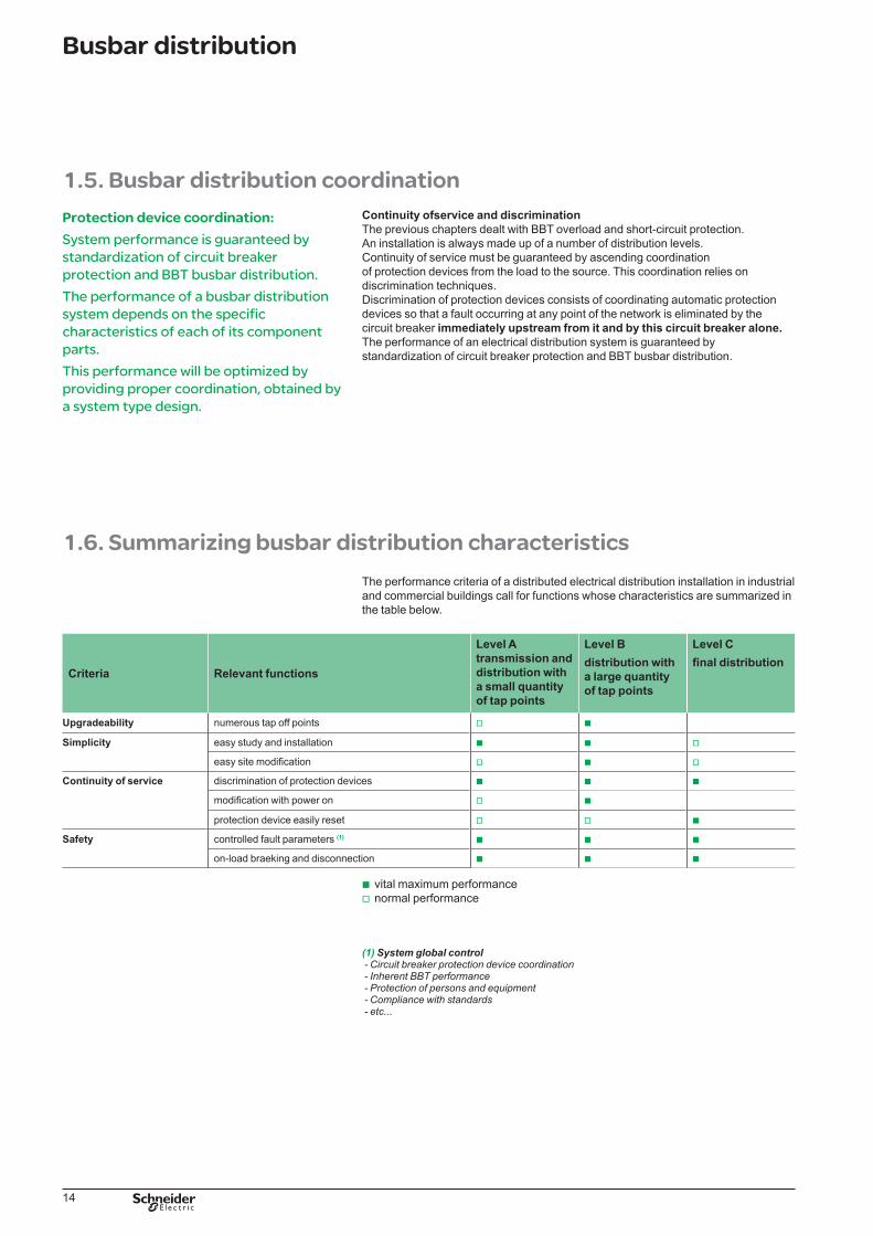
Application: enhanced BBT protectionThis cascading technique also considerably enhances BBT withstand characteristics with respect to the assumed short-circuit current.In the diagram opposite the KSA40 busbar trunking is protected by the NSX400N circuit breaker (D�). A KSA�6 tap off protected by an NSX�60F (D2) circuit breaker is placed on this busbar trunking.
Without coordination, the very high limiting capacity of the NSX�60F alone already protects the KSA�6 up to its ultimate breaking capacity Icu, i.e. 35 kA.
However coordination performance is enhanced as a result of enhanced coordination with the upstream NSX400N:
enhanced breaking capacity of the NSX�60F which rises to 45 kA,enhanced discrimination: due to the techniques developed in the NSX type
ranges, discrimination is total between the 2 protection devices, in other words up to the enhanced breaking capacity of D2, i.e. 45 kA.
enhanced busbar trunking withstand: tested coordination of Canalis KSA�6 is enhanced up to the enhanced Isc of the NSX�60F, i.e. 45 kA.
This exclusive Schneider Electric system feature increases:reliability, thanks to the high limitation of short-circuit current thermal and
electrodynamic stressescontinuity of electrical distribution service thanks to the increased
discrimination level.
BBT protection BBT protection in coordination
Canalis KSA 16 Protected by limiting D2 NSX�60F Icu = 35 kA
Protected by limiting D2 NSX�60F Icu = 35 kA coordinated upstream with D� NSX400N Icu = 45 kA
Protection limit KSA�6 Isc = 35 kA Isc = 45 kA
Descrimination limit Up to max. Isc = 35 kA according to upstream
Up to max. Isc = 45 kA guaranteed
KSA16 characteristic Maximum stresses on BBT if a short-circuit occurs
Peak I = 22 k A2s = 20,2 �06
Isc = 35 kA IL = �9 k A2s = 0,52 �06
Isc = 45 kA IL = 20 k A2s = 0,6 �06
b
b
vv
v
b
b
DB
�252
02
Enhanced protection of a KSA-16 BBT by an NSX160Fcircuit breaker coordinated with an NSX400N circuit breaker.
DB
�252
02
Enhanced protection of a KSA-16 BBT by an NSX160Fcircuit breaker coordinated with an NSX400N circuit breaker.
2.3. Final distribution
The following diagrams optimize all the functions required for all industrial and commercial building applications.
Protectionswitchboard overcurrent protection is provided by the protection circuit breaker
(DD) installed in the tap off box.feeder protection is provided by the circuit-breakers (DCI) installed at each feeder.
Continuity of service is optimum at feeder level:thanks to enhanced total discrimination between the protection devicesthanks to easy access and resetting of the protection devices.
Maintenance The switchboard incoming switch (IS) guarantees disconnection and thus safety for maintenance, servicing and upgrading of the installation.
b
b
bb
22
The Schneider Electic busbar distribution System
On-load opening This function is performed by a switch. The incoming switch places the installation out of operation should a problem arise, either by manual control or automatically using an emergency punch button. This safety function requires a high degree of reliability should a fault occur on the electrical installation.
DB
�253
56
DD
IS
DCI
Canalis
tap offcircuit breaker
isolatingswitch
Industrialcontrolcircuit breaker
automationcubicle
connectingcable
DB
�253
57
Canalis
tap offcircuit breaker
isolatingswitch
final distributioncircuit breaker
final distributionenclosure
connectingcable
2.4. Advantages of the Schneider Electric system
BBT protectionSchneider Electric circuit breakers offer:
overload and short-circuit protection,an extensive setting range and thus protection device standardization,coordination between the protection devices and the Telemecanique Canalis BBTs:total discrimination: � to 6300 A between all Merlin Gerin circuit breakerscascading:enhancement of low and medium power BBT short-circuit protection devices, thus
meeting all the short-circuit levels encountered.tap off protection using standard circuit breakers regardless of where the tap off
box is placed on the Canalis BBT.use of standard circuit breakers simplifies the study process, while ensuring a high
degree of dependability.quick, easy fault tracking.simple reclosing (“resetting”) once the fault has been eliminated by the operator.
Tap off boxesThe Schneider Electric Canalis tap off boxes satisfy operators’ needs in terms of:
installation upgradeability without production downtimescontinuity of servicesafety.
The tap off boxes:can be connected and disconnected with power on without risk to the operatorare designed for installation at one-meter intervals on the distribution BBTs.
bbbvv-
-
b
bb
bbb
bb
DB
�252
05
Canalis KSA busbar trunking.
DB
�252
05
Tap off box.
DB
�252
05
Canalis KSA busbar trunking.
DB
�252
05
Tap off box.

23
The Schneider Electic busbar distribution System
Final distribution The protection switchgear optimizes switchboard functions.
Coordination of upstream protection devices is provided and guaranteed by Schneider Electric:
for distribution applications between Masterpact, Compact C, Compact NSX circuit breakers and Multi 9 circuit breakers.
for industrial control applications between circuit breakers and control (motor circuit breaker, Integral,...).The coordination tables are available in the relevant product catalogs.The Schneider Electric switches comply with the IEC 60947-3 standard, and are designed to ensure AC23 on-load breaking and disconnection. Their protection is guaranteed by coordination with the upstream circuit breakers.
b
v
v
DB
�252
07
DB
�252
�6
Prisma enclosure.
Automation enclosure.
DB
�252
�7
Switch.
DB
�252
07
DB
�252
�6
Prisma enclosure.
Automation enclosure.
DB
�252
�7
Switch.
2.5. Advantages and exclusive features of the Schneider Electric system
Total coordination of the Schneider Electric system guarantees and enhances safety of persons and equipment, continuity of service and installation upgradeability and simplicity.Total coordination is materialized by:
Comprehensive coordination choice guide tablesSchneider Electric proposes coordination tables for a busbar distribution system
from � to 5000 A:circuit breakers: Multi 9, Compact NSX, Compact CM, Masterpact from � to 6300 A.BBT: lighting BBT, low, medium and high power distribution BBT.Whatever the installation’s short-circuit current, 2 table types directly supply the
appropriate BBTs and circuit breakers:one to ensure coordinationthe other to ensure cascading and enhanced discrimination.
Standard performance circuit breakers for all Isc y 70 kAThe BBT tap off boxes are equipped with standard Compact NS circuit breakers and can be installed at any point of the BBT.
Optimization of the tap off box offerThe extensive setting ranges of the circuit breakers equipped with electronic trip units.
in thermal protection, Ir is adjustable from 0.4 to In,in short-circuit protection, Im is adjustable from 2 to �0 Ir,
allow optimization of the tap off box stocks required for maintenance and extension purposes.This feature helps enhance the natural flexibility and upgradeability of the BBTs.
b
vvvb
vv
bb

24
The Schneider Electic busbar distribution System
Summarizing table
Criteria Relevant functions
Level ATransmission and distribution with a small quantity of tap points
Level BDistribution with a large quantity of tap points
Level CFinal distribution
Upgradeability One tap off connection every meter BBT
Extensive setting range of protection devices CB CB
Easy installation BBT BBT
Standard performance circuit breakers for all Isc y 70 kA ● CB CB
Simplicity Comprehensive coordination choice guide tablr ● BBT, CB BBT, CB BBT, CB
Optimization of the tap off box offer ● CB CB
Easy, rapid BBT installation BBT BBT
Easy installation modification BBT BBT
Extensive protection enclosure range BBT BBTContinuty of service Total discrimination of BBT protection devices ● BBT, CB BBT, CB
Total discrimination of protection devices for all Merlin Gerin and Telemecanique circuit breaker ranges (1)
● CB
Modification without production downtimes BBT BBT
Easily resettable protection device CB CB CBSafety of persons and equipment
System coordinated from 40 to 5000 A cascading and total coordination of protection devices ● BBT, CB BBT, CB BBT, CB
On load breaking and disconnected coordinated with upstream protection devices CB CB CB
Testable protection devices CB CB CB
Polarized tap off boxes BBT BBT
● : exclusive advantage of the Schneider Electric system.
BBT : performance owed to the Canalis BBTsCB : perfromance due to the circuit breakersBBT, CB : performance due to the coordination between BBTs and circuit breaker
(1) In particular thanks to :■ a system coordinated from 40 to 5000 A■ cascading and total coordinition of protection device.

������������� ��������������������
�����������

06-2009DBTP118EN
Schneider Electric Industries SAS35, rue Joseph MonierCS 30323F- 92506 Rueil Malmaison Cedex
RCS Nanterre 954 503 439Capital social 896 313 776 €www.schneider-electric.com
© 2
009
-Sch
neid
erE
lect
ric-�
llri�
hts
rese
r�ed
.20
09 -
Sch
neid
er E
lect
ric -
�ll
ri�ht
s re
ser�
ed.
As standards, specifications and designs change from time to time, please ask for confirmation of the information given in this publication.
This document has been printed on ecological paper
Desi�n: Schneider ElectricPhotos: Schneider ElectricPrinted:
Recommended