Version 6.2February 2011
Document #: LTRT‐28600
AudioCodes™ SIP Products
VoIP Mediant™ Media Gateways
Multi‐Service Business Gateways
Technical Note Configuring the Syslog Feature

Technical Note Contents
Version 6.2 3 February 2011
Table of Contents
1 Introduction ......................................................................................................... 7
2 Available Syslog Servers .................................................................................... 9
3 Syslog Message Format ................................................................................... 11
3.1 Unique Device Identification in Syslog Messages .................................................. 12 3.2 Identifying AudioCodes Syslog Messages using Facility Levels ............................ 12 3.3 SNMP Alarms in Syslog Messages ........................................................................ 13 3.4 Syslog Message Display in the Web Interface ....................................................... 14
4 Configuring the Syslog Feature ....................................................................... 15
5 Call Detail Record Reporting ............................................................................ 19
5.1 Configuring CDR .................................................................................................... 19 5.2 CDR Fields ............................................................................................................. 21

Technical Note 4 Document #: LTRT-28600
Configuring Syslog
List of Figures Figure 2-1: AudioCodes Proprietary Syslog Server - ACSyslog .............................................................. 9 Figure 3-1: Viewing Syslog Messages in the Web Interface .................................................................. 14 Figure 4-1: Configuring Syslog in the Web Interface ............................................................................. 15 Figure 5-1: Configuring CDR Reporting in the Web Interface ................................................................ 20
List of Tables Table 3-1: Syslog Facility Levels ............................................................................................................ 12 Table 3-2: Syslog Message Severity ...................................................................................................... 13 Table 4-1: Syslog Parameters Description ............................................................................................. 16 Table 5-1: Supported CDR Fields .......................................................................................................... 21
Technical Note Notices
Version 6.2 5 February 2011
Notice
This document describes AudioCodes Syslog feature.
Information contained in this document is believed to be accurate and reliable at the time of printing. However, due to ongoing product improvements and revisions, AudioCodes cannot guarantee the accuracy of printed material after the Date Published nor can it accept responsibility for errors or omissions. Updates to this document and other documents as well as software files can be viewed by registered customers at http://www.audiocodes.com/downloads.
© Copyright 2011 AudioCodes Ltd. All rights reserved.
This document is subject to change without notice.
Date Published: February-13-2011
Trademarks
AudioCodes, AC, AudioCoded, Ardito, CTI2, CTI², CTI Squared, HD VoIP, HD VoIP Sounds Better, InTouch, IPmedia, Mediant, MediaPack, NetCoder, Netrake, Nuera, Open Solutions Network, OSN, Stretto, TrunkPack, VMAS, VoicePacketizer, VoIPerfect, VoIPerfectHD, What’s Inside Matters, Your Gateway To VoIP and 3GX are trademarks or registered trademarks of AudioCodes Limited. All other products or trademarks are property of their respective owners. Product specifications are subject to change without notice.
WEEE EU Directive
Pursuant to the WEEE EU Directive, electronic and electrical waste must not be disposed of with unsorted waste. Please contact your local recycling authority for disposal of this product.
Customer Support
Customer technical support and service are provided by AudioCodes’ Distributors, Partners, and Resellers from whom the product was purchased. For Customer support for products purchased directly from AudioCodes, contact [email protected].
Abbreviations and Terminology
Each abbreviation, unless widely used, is spelled out in full when first used.
Note: Throughout this document and unless otherwise specified, the term device denotes AudioCodes product.

Technical Note 6 Document #: LTRT-28600
Configuring Syslog
Reader's Company
Technical Note 1. Introduction
Version 6.2 7 February 2011
1 Introduction Syslog is an event notification protocol that enables a device to send event notification messages across IP networks to event message collectors, also known as Syslog servers. The device contains an embedded syslog client, which sends error reports / events that it generates to a remote Syslog server using the IP / UDP protocol. This information is a collection of error, warning, and system messages that records every internal operation of the device.
Notes:
• For a detailed description of the Syslog feature, refer to the SIP Product Reference Manual and the device’s User’s Manual.
• This document is applicable to the following products: MediaPack series (MP-11x and MP-124), Mediant 600, Mediant 1000, Mediant 800 MSBG, Mediant 1000 MSBG, Mediant 2000, and Mediant 3000.

Technical Note 8 Document #: LTRT-28600
Configuring Syslog
Reader's Notes
Technical Note 2. Available Syslog Servers
Version 6.2 9 February 2011
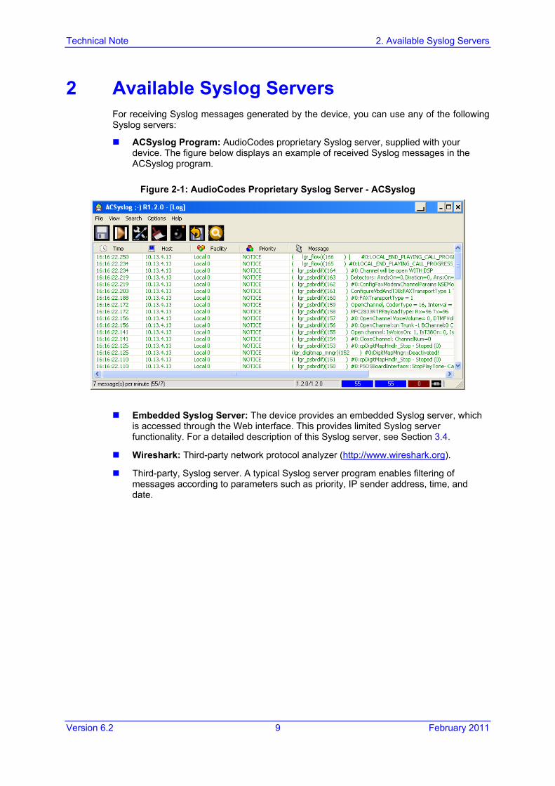
2 Available Syslog Servers For receiving Syslog messages generated by the device, you can use any of the following Syslog servers:
ACSyslog Program: AudioCodes proprietary Syslog server, supplied with your device. The figure below displays an example of received Syslog messages in the ACSyslog program.
Figure 2-1: AudioCodes Proprietary Syslog Server - ACSyslog
Embedded Syslog Server: The device provides an embedded Syslog server, which is accessed through the Web interface. This provides limited Syslog server functionality. For a detailed description of this Syslog server, see Section 3.4.
Wireshark: Third-party network protocol analyzer (http://www.wireshark.org).
Third-party, Syslog server. A typical Syslog server program enables filtering of messages according to parameters such as priority, IP sender address, time, and date.

Technical Note 10 Document #: LTRT-28600
Configuring Syslog
Reader's Notes
Technical Note 3. Syslog Message Format
Version 6.2 11 February 2011
3 Syslog Message Format The Syslog message is transmitted from the device to a Syslog server as an American Standard Code for Information Interchange (ASCII) message. Syslog servers use User Datagram Protocol (UDP) as its underlying transport layer. By default, UDP port 514 is assigned to Syslog. This port can be changed using the SyslogServerPort parameter.
Syslog generates the following types of messages:
Error: indicates a problem has been identified that requires immediate handling
Warning: indicates an error might occur if measures are not taken to prevent it
Notice: indicates an unusual event has occurred
Info: indicates an operational message
Debug: messages used for debugging
When using the device’s embedded Syslog server, these message types are color coded (as explained in Section 3.4).
Note: Info and Debug Syslog messages are required only for advanced debugging. Therefore, they are not sent by default.
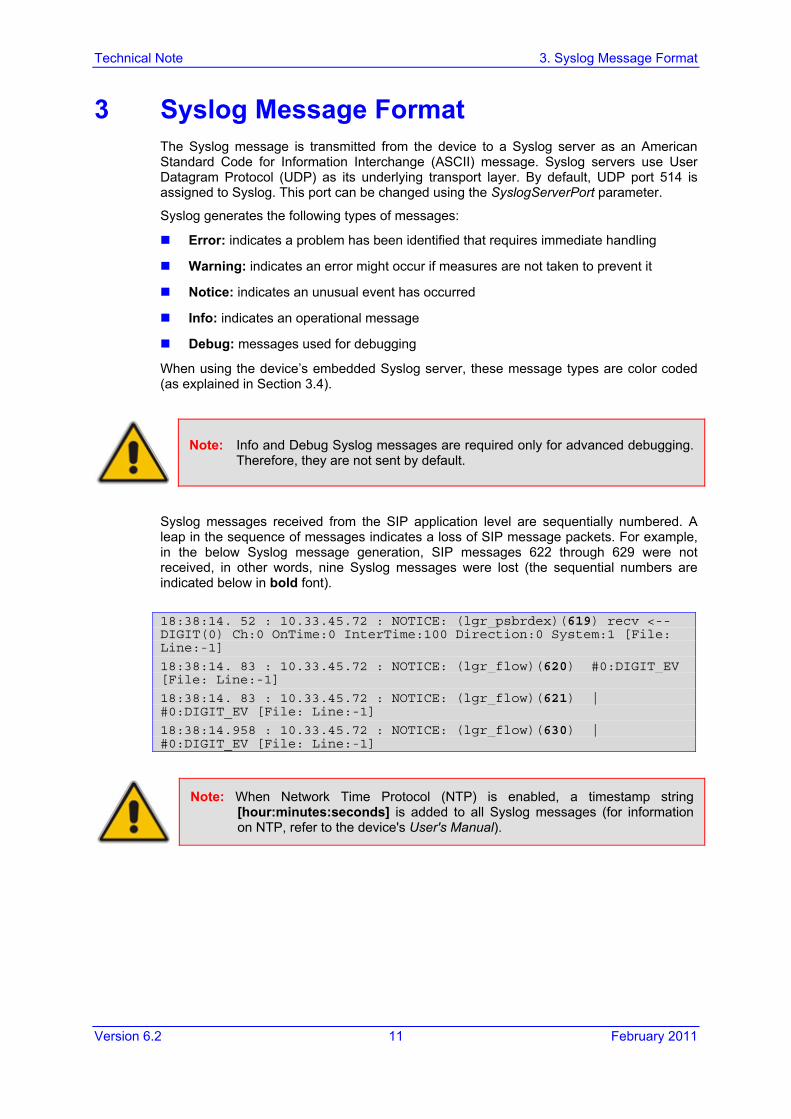
Syslog messages received from the SIP application level are sequentially numbered. A leap in the sequence of messages indicates a loss of SIP message packets. For example, in the below Syslog message generation, SIP messages 622 through 629 were not received, in other words, nine Syslog messages were lost (the sequential numbers are indicated below in bold font).
18:38:14. 52 : 10.33.45.72 : NOTICE: (lgr_psbrdex)(619) recv <-- DIGIT(0) Ch:0 OnTime:0 InterTime:100 Direction:0 System:1 [File: Line:-1]
18:38:14. 83 : 10.33.45.72 : NOTICE: (lgr_flow)(620) #0:DIGIT_EV [File: Line:-1]
18:38:14. 83 : 10.33.45.72 : NOTICE: (lgr_flow)(621) | #0:DIGIT_EV [File: Line:-1]
18:38:14.958 : 10.33.45.72 : NOTICE: (lgr_flow)(630) | #0:DIGIT_EV [File: Line:-1]
Note: When Network Time Protocol (NTP) is enabled, a timestamp string [hour:minutes:seconds] is added to all Syslog messages (for information on NTP, refer to the device's User's Manual).
Technical Note 12 Document #: LTRT-28600
Configuring Syslog
3.1 Unique Device Identification in Syslog Messages For MSBG and Mediant 3000 devices, the Syslog messages include a unique string to identify these devices:
Mediant 800 MSBG and Mediant 1000 MSBG: Syslog messages relating to VoIP functionality are marked with “host”; those relating to Data Routing are marked with “DATA”.
12/12 12:46:40.921 : 10.8.5.70 : NOTICE : host: 10.8.5.78 (sip_stack)(24) Resource SIPMessage deleted - #267
11/24 08:14:09.311 : 10.3.2.100 : WARNING : DATA: Failed to set device eth0 netmask: Cannot assign requested address
Mediant 3000: High Availability (HA) main operations and events are sent to the
Syslog with the prefix, “M3K_HA”. All Syslog messages and events of the redundant TP-6310 blade are sent to the Syslog by the active TP-6310 blade with the “Redundant module message” message prefix.
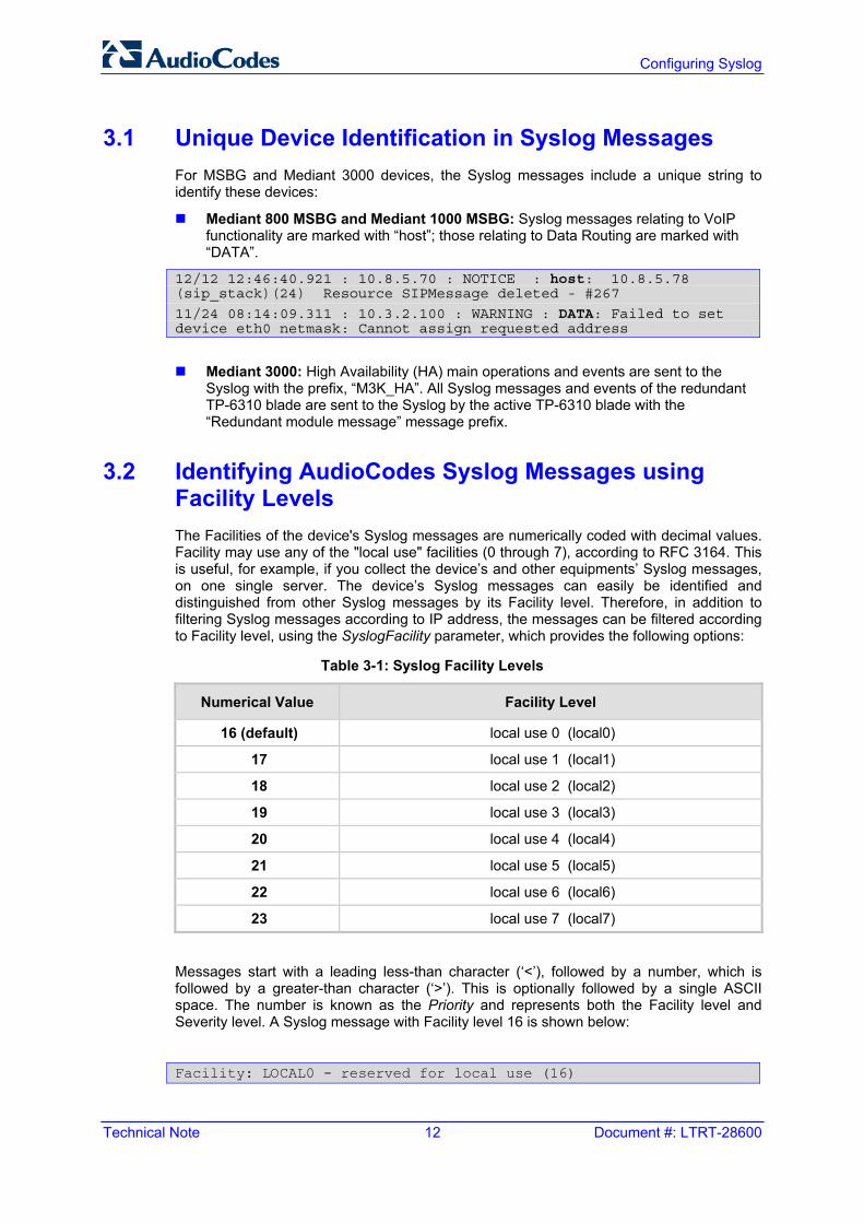
3.2 Identifying AudioCodes Syslog Messages using Facility Levels The Facilities of the device's Syslog messages are numerically coded with decimal values. Facility may use any of the "local use" facilities (0 through 7), according to RFC 3164. This is useful, for example, if you collect the device’s and other equipments’ Syslog messages, on one single server. The device’s Syslog messages can easily be identified and distinguished from other Syslog messages by its Facility level. Therefore, in addition to filtering Syslog messages according to IP address, the messages can be filtered according to Facility level, using the SyslogFacility parameter, which provides the following options:
Table 3-1: Syslog Facility Levels
Numerical Value Facility Level
16 (default) local use 0 (local0)
17 local use 1 (local1)
18 local use 2 (local2)
19 local use 3 (local3)
20 local use 4 (local4)
21 local use 5 (local5)
22 local use 6 (local6)
23 local use 7 (local7)
Messages start with a leading less-than character (‘<’), followed by a number, which is followed by a greater-than character (‘>’). This is optionally followed by a single ASCII space. The number is known as the Priority and represents both the Facility level and Severity level. A Syslog message with Facility level 16 is shown below:
Facility: LOCAL0 - reserved for local use (16)
Technical Note 3. Syslog Message Format
Version 6.2 13 February 2011
3.3 SNMP Alarms in Syslog Messages SNMP is a protocol that alerts you when a network-attached device requires attention. SNMP alerts are sent to the Syslog server using the following formats:
Raised Alarms: RAISE-ALARM: <Alarm Name>; Textual Description: <Textual Description>; Severity <Alarm Severity>; Source <Alarm Source>; Unique ID: <Alarm Unique ID >.
If additional information exists in the alarm, then these are also added: Additional Info1:/ Additional Info2:/ Additional Info3
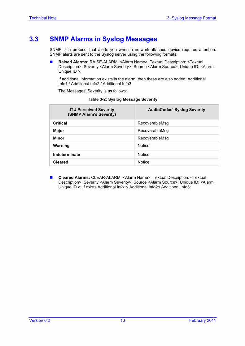
The Messages’ Severity is as follows:
Table 3-2: Syslog Message Severity
ITU Perceived Severity (SNMP Alarm’s Severity)
AudioCodes' Syslog Severity
Critical RecoverableMsg
Major RecoverableMsg
Minor RecoverableMsg
Warning Notice
Indeterminate Notice
Cleared Notice
Cleared Alarms: CLEAR-ALARM: <Alarm Name>; Textual Description: <Textual Description>; Severity <Alarm Severity>; Source <Alarm Source>; Unique ID: <Alarm Unique ID >; If exists Additional Info1:/ Additional Info2:/ Additional Info3:
Technical Note 14 Document #: LTRT-28600
Configuring Syslog
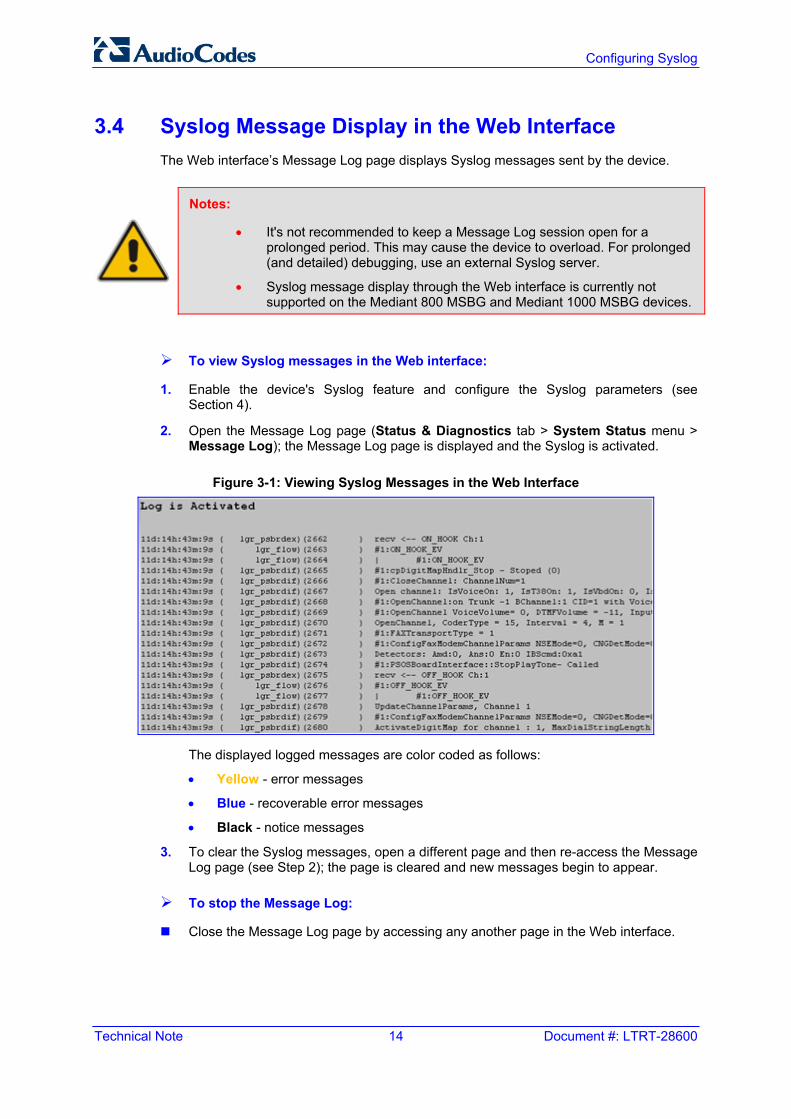
3.4 Syslog Message Display in the Web Interface The Web interface’s Message Log page displays Syslog messages sent by the device.
Notes:
• It's not recommended to keep a Message Log session open for a prolonged period. This may cause the device to overload. For prolonged (and detailed) debugging, use an external Syslog server.
• Syslog message display through the Web interface is currently not supported on the Mediant 800 MSBG and Mediant 1000 MSBG devices.
To view Syslog messages in the Web interface:
1. Enable the device's Syslog feature and configure the Syslog parameters (see Section 4).
2. Open the Message Log page (Status & Diagnostics tab > System Status menu > Message Log); the Message Log page is displayed and the Syslog is activated.
Figure 3-1: Viewing Syslog Messages in the Web Interface
The displayed logged messages are color coded as follows:
• Yellow - error messages
• Blue - recoverable error messages
• Black - notice messages
3. To clear the Syslog messages, open a different page and then re-access the Message Log page (see Step 2); the page is cleared and new messages begin to appear.
To stop the Message Log:
Close the Message Log page by accessing any another page in the Web interface.
Technical Note 4. Configuring the Syslog Feature
Version 6.2 15 February 2011
4 Configuring the Syslog Feature The Syslog client, which is embedded in the device sends error reports/events generated by the device to a Syslog server using IP/UDP protocol. The Syslog can be configured using the Web interface, EMS, or ini file. The main configuration of the Syslog feature includes enabling the Syslog client, defining the Syslog server’s IP address, and then selecting the debug level.
The procedure below describes how to configure Syslog for receiving SIP messages through the Web interface.
To configure Syslog for receiving SIP message events:
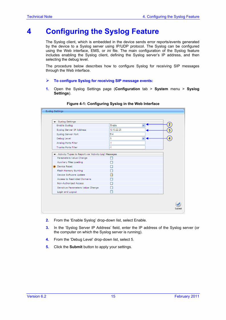
1. Open the Syslog Settings page (Configuration tab > System menu > Syslog Settings).
Figure 4-1: Configuring Syslog in the Web Interface
2. From the ‘Enable Syslog’ drop-down list, select Enable.
3. In the ‘Syslog Server IP Address’ field, enter the IP address of the Syslog server (or the computer on which the Syslog server is running).
4. From the ‘Debug Level’ drop-down list, select 5.
5. Click the Submit button to apply your settings.
2
3
4
Technical Note 16 Document #: LTRT-28600
Configuring Syslog
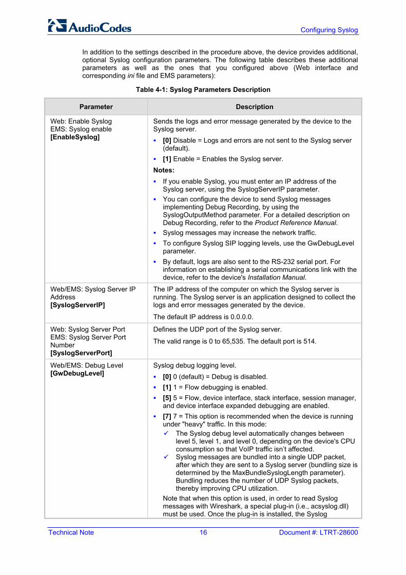
In addition to the settings described in the procedure above, the device provides additional, optional Syslog configuration parameters. The following table describes these additional parameters as well as the ones that you configured above (Web interface and corresponding ini file and EMS parameters):
Table 4-1: Syslog Parameters Description
Parameter Description
Web: Enable Syslog EMS: Syslog enable [EnableSyslog]
Sends the logs and error message generated by the device to the Syslog server. [0] Disable = Logs and errors are not sent to the Syslog server
(default). [1] Enable = Enables the Syslog server.
Notes: If you enable Syslog, you must enter an IP address of the
Syslog server, using the SyslogServerIP parameter. You can configure the device to send Syslog messages
implementing Debug Recording, by using the SyslogOutputMethod parameter. For a detailed description on Debug Recording, refer to the Product Reference Manual.
Syslog messages may increase the network traffic. To configure Syslog SIP logging levels, use the GwDebugLevel
parameter. By default, logs are also sent to the RS-232 serial port. For
information on establishing a serial communications link with the device, refer to the device's Installation Manual.
Web/EMS: Syslog Server IP Address [SyslogServerIP]
The IP address of the computer on which the Syslog server is running. The Syslog server is an application designed to collect the logs and error messages generated by the device.
The default IP address is 0.0.0.0.
Web: Syslog Server Port EMS: Syslog Server Port Number [SyslogServerPort]
Defines the UDP port of the Syslog server.
The valid range is 0 to 65,535. The default port is 514.
Web/EMS: Debug Level [GwDebugLevel]
Syslog debug logging level. [0] 0 (default) = Debug is disabled. [1] 1 = Flow debugging is enabled. [5] 5 = Flow, device interface, stack interface, session manager,
and device interface expanded debugging are enabled. [7] 7 = This option is recommended when the device is running
under "heavy" traffic. In this mode: The Syslog debug level automatically changes between
level 5, level 1, and level 0, depending on the device's CPU consumption so that VoIP traffic isn’t affected.
Syslog messages are bundled into a single UDP packet, after which they are sent to a Syslog server (bundling size is determined by the MaxBundleSyslogLength parameter). Bundling reduces the number of UDP Syslog packets, thereby improving CPU utilization.
Note that when this option is used, in order to read Syslog messages with Wireshark, a special plug-in (i.e., acsyslog.dll) must be used. Once the plug-in is installed, the Syslog
Technical Note 4. Configuring the Syslog Feature
Version 6.2 17 February 2011
Parameter Description
messages are decoded as "AC SYSLOG" and are dispalyed using the ‘acsyslog’ filter instead of the regular ‘syslog’ filter..
Notes: Usually set to 5 if debug traces are required. However, in cases
of heavy traffic, option 7 is recommended. Options 2, 3, 4, and 6 are not recommended for use.
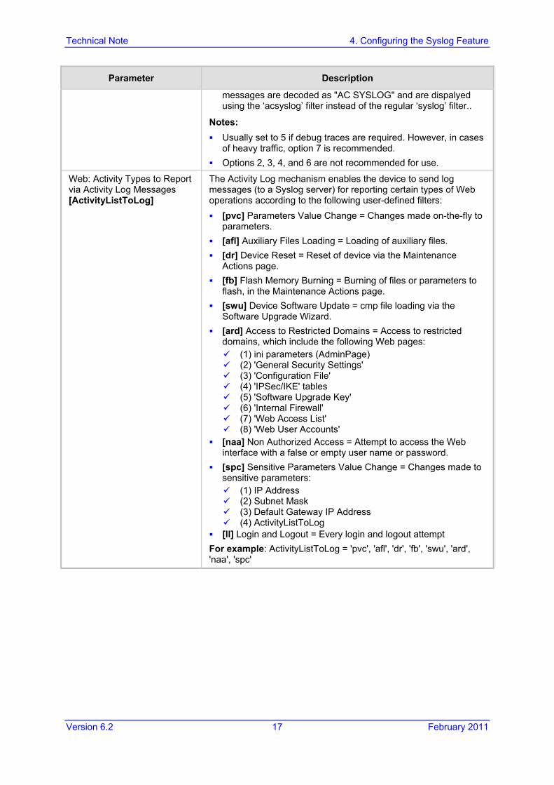
Web: Activity Types to Report via Activity Log Messages [ActivityListToLog]
The Activity Log mechanism enables the device to send log messages (to a Syslog server) for reporting certain types of Web operations according to the following user-defined filters: [pvc] Parameters Value Change = Changes made on-the-fly to
parameters. [afl] Auxiliary Files Loading = Loading of auxiliary files. [dr] Device Reset = Reset of device via the Maintenance
Actions page. [fb] Flash Memory Burning = Burning of files or parameters to
flash, in the Maintenance Actions page. [swu] Device Software Update = cmp file loading via the
Software Upgrade Wizard. [ard] Access to Restricted Domains = Access to restricted
domains, which include the following Web pages: (1) ini parameters (AdminPage) (2) 'General Security Settings' (3) 'Configuration File' (4) 'IPSec/IKE' tables (5) 'Software Upgrade Key' (6) 'Internal Firewall' (7) 'Web Access List' (8) 'Web User Accounts'
[naa] Non Authorized Access = Attempt to access the Web interface with a false or empty user name or password.
[spc] Sensitive Parameters Value Change = Changes made to sensitive parameters:
(1) IP Address (2) Subnet Mask (3) Default Gateway IP Address (4) ActivityListToLog
[ll] Login and Logout = Every login and logout attempt For example: ActivityListToLog = 'pvc', 'afl', 'dr', 'fb', 'swu', 'ard', 'naa', 'spc'
Technical Note 18 Document #: LTRT-28600
Configuring Syslog
Parameter Description
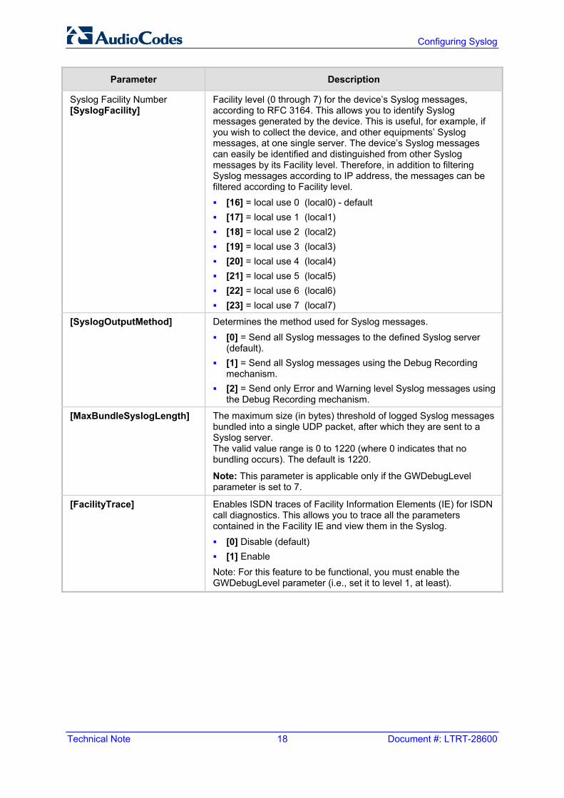
Syslog Facility Number [SyslogFacility]
Facility level (0 through 7) for the device’s Syslog messages, according to RFC 3164. This allows you to identify Syslog messages generated by the device. This is useful, for example, if you wish to collect the device, and other equipments’ Syslog messages, at one single server. The device’s Syslog messages can easily be identified and distinguished from other Syslog messages by its Facility level. Therefore, in addition to filtering Syslog messages according to IP address, the messages can be filtered according to Facility level. [16] = local use 0 (local0) - default [17] = local use 1 (local1) [18] = local use 2 (local2) [19] = local use 3 (local3) [20] = local use 4 (local4) [21] = local use 5 (local5) [22] = local use 6 (local6) [23] = local use 7 (local7)
[SyslogOutputMethod] Determines the method used for Syslog messages. [0] = Send all Syslog messages to the defined Syslog server
(default). [1] = Send all Syslog messages using the Debug Recording
mechanism. [2] = Send only Error and Warning level Syslog messages using
the Debug Recording mechanism.
[MaxBundleSyslogLength] The maximum size (in bytes) threshold of logged Syslog messages bundled into a single UDP packet, after which they are sent to a Syslog server. The valid value range is 0 to 1220 (where 0 indicates that no bundling occurs). The default is 1220.
Note: This parameter is applicable only if the GWDebugLevel parameter is set to 7.
[FacilityTrace] Enables ISDN traces of Facility Information Elements (IE) for ISDN call diagnostics. This allows you to trace all the parameters contained in the Facility IE and view them in the Syslog. [0] Disable (default) [1] Enable
Note: For this feature to be functional, you must enable the GWDebugLevel parameter (i.e., set it to level 1, at least).
Technical Note 5. Call Detail Record Reporting
Version 6.2 19 February 2011
5 Call Detail Record Reporting The Call Detail Record (CDR) contains important statistic information on calls made from the device. The device can be configured to generate and report CDRs for various stages of the call (beginning, initial connection, and end of the call). Once generated, the CDR logs are sent to a user-defined Syslog server.
The CDR Syslog message complies with RFC 3161 and is identified by Facility = 17 (local1) and Severity = 6 (Informational).
5.1 Configuring CDR The procedure below describes how to configure CDR reporting.
Note: For CDR reporting, you must also enable the Syslog feature (refer to Section 4).
To configure CDR:
1. Open the 'Advanced Parameters' page (Configuration tab > VoIP menu > SIP Definitions submenu > Advanced Parameters).
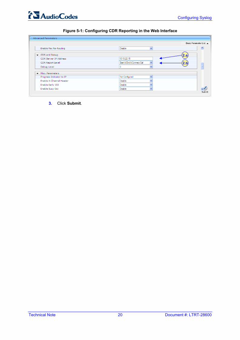
2. Under the CDR and Debug group, perform the following:
a. In the 'CDR Server IP Address' field, enter the IP address of the CDR server to where the device sends the CDR logs.
Note: If no IP address is defined, the CDR logs are sent to the Syslog server (as defined in Section 4).
b. From the 'CDR Report Level' drop-down list, select when the CDR's are
generated and sent to the CDR server: ♦ [0] None = CDRs are not used (default).
♦ [1] End Call = CDR is sent to the Syslog server at the end of each call.
♦ [2] Start & End Call = CDR report is sent to Syslog server at the start and end of each call.
♦ [3] Connect & End Call = CDR report is sent to the Syslog server at connection and at the end of each call.
♦ [4] Start & End & Connect Call = CDR report is sent to the Syslog server at the start, at connection, and at the end of each call.
Technical Note 20 Document #: LTRT-28600
Configuring Syslog
Figure 5-1: Configuring CDR Reporting in the Web Interface
3. Click Submit.
2.a
2.b
Technical Note 5. Call Detail Record Reporting
Version 6.2 21 February 2011
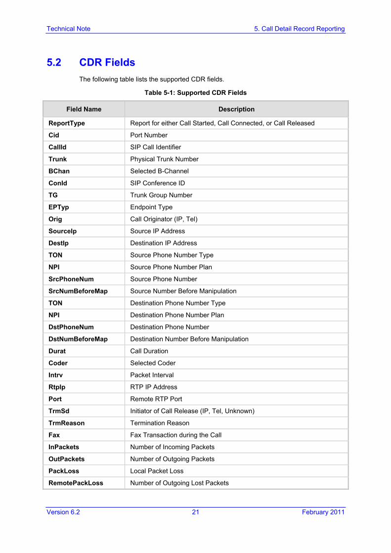
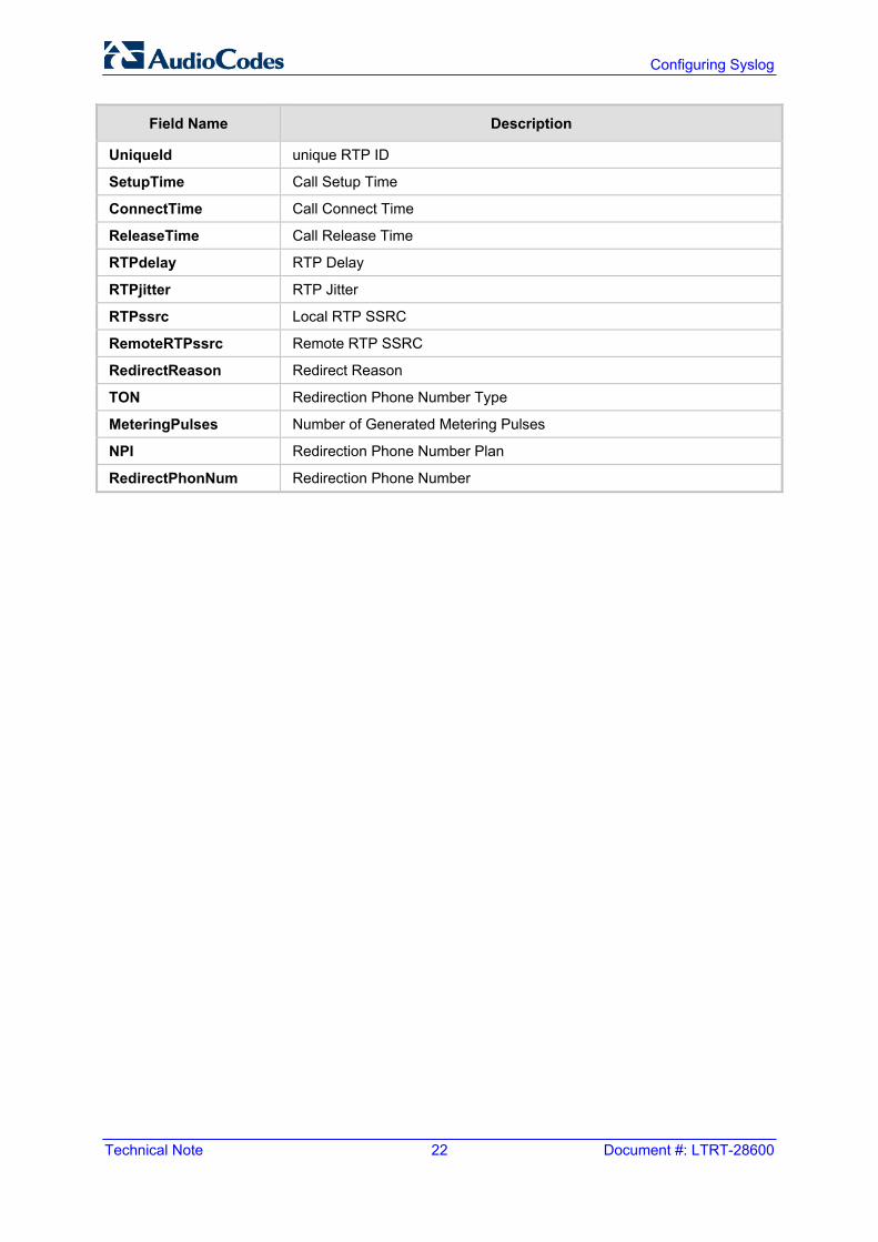
5.2 CDR Fields The following table lists the supported CDR fields.
Table 5-1: Supported CDR Fields
Field Name Description
ReportType Report for either Call Started, Call Connected, or Call Released
Cid Port Number
CallId SIP Call Identifier
Trunk Physical Trunk Number
BChan Selected B-Channel
ConId SIP Conference ID
TG Trunk Group Number
EPTyp Endpoint Type
Orig Call Originator (IP, Tel)
SourceIp Source IP Address
DestIp Destination IP Address
TON Source Phone Number Type
NPI Source Phone Number Plan
SrcPhoneNum Source Phone Number
SrcNumBeforeMap Source Number Before Manipulation
TON Destination Phone Number Type
NPI Destination Phone Number Plan
DstPhoneNum Destination Phone Number
DstNumBeforeMap Destination Number Before Manipulation
Durat Call Duration
Coder Selected Coder
Intrv Packet Interval
RtpIp RTP IP Address
Port Remote RTP Port
TrmSd Initiator of Call Release (IP, Tel, Unknown)
TrmReason Termination Reason
Fax Fax Transaction during the Call
InPackets Number of Incoming Packets
OutPackets Number of Outgoing Packets
PackLoss Local Packet Loss
RemotePackLoss Number of Outgoing Lost Packets
Technical Note 22 Document #: LTRT-28600
Configuring Syslog
Field Name Description
UniqueId unique RTP ID
SetupTime Call Setup Time
ConnectTime Call Connect Time
ReleaseTime Call Release Time
RTPdelay RTP Delay
RTPjitter RTP Jitter
RTPssrc Local RTP SSRC
RemoteRTPssrc Remote RTP SSRC
RedirectReason Redirect Reason
TON Redirection Phone Number Type
MeteringPulses Number of Generated Metering Pulses
NPI Redirection Phone Number Plan
RedirectPhonNum Redirection Phone Number

Technical Note 5. Call Detail Record Reporting
Version 6.2 23 February 2011
Reader’s Notes

Technical Note
www.audiocodes.com
Recommended