1
The 2nd Regional Stakeholder ForumThe Pak Beng Hydropower Project5th May 2017 Vientiane, Lao PDR
Technical Review of Pak Beng Hydropower Project – Navigation

Background
Main Review Findings
Recommendations
Contents
Background
• Document reviewed:⁻ Hydrodynamic characteristics research on valve
and culvert section for Pak Beng ship Lock, September 2015.
⁻ Engineering status report, September 2015⁻ Engineering status report Drawings, September
2015.• Discussions with Ministry of Energy and Mines
representatives• Discussions with PB Project designers and
developers

The main concern: the current proposal is for a single lift system which needs more than 30m to lift or lower shipping • MRC Design guidance for Mekong mainstream dams:
“greater than 30m lift should use two locks in a series (tandem);
• The single lift proposed for Pak Beng dam: 36.46m high• Problem of single lift: There have been many studies on
cavitation problems in high lift ship locks, particularly with the valves
• It is recommended that the single lift system be redesigned to a double lift system.
Main Review FindingsSingle lift lock or tandem lock?

• The current design is similar to the Yingpan lock which has cavitation and heavy vibration.
• Several locks with similar water heads, amongst others the John Day lock, have encountered severe cavitation problems.
Cavitation problem

Pak Beng and Xayabouri (same scale)

Important remark: The size of vessels
With a lock chamber of 120m x 12m x 4m ships of class Va (CEMT classification) can enter the ship lock with limited draft (less than 3.50m)

Important remark: The size of vesselsIn comparison with the Chinese ship classification, a convoy of 2 x 500t (IV China) can be accommodated.
Upstream approach channel
• The upstream approach channel is narrow: The downstream approach layout is the mirror of the upstream approach with preferably the guiding wall on the same river bank.
• PIANC recommendation: sufficient lay‐by area for vessels, waiting area (in accordance with the traffic) and overnight berths
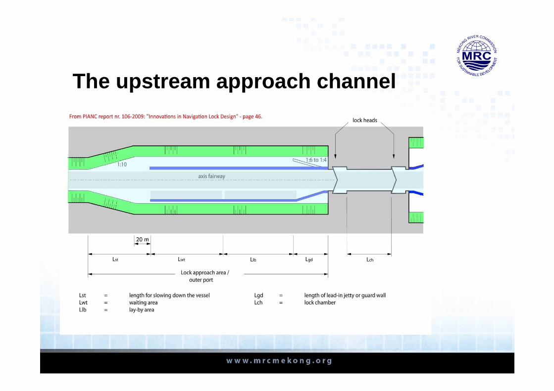
The upstream approach channel

The upstream approach channel
These pontoons should be fixed by dolphins
Two additional pontoons under angle for widening the access

The upstream approach channel

The upstream approach channelFixing the floating pontoons by dolphins

The upstream approach channelThe upstream approach wall
• Will have to be broken down for the future eventual construction of the second lock
• Heavy duty in massive reinforce concrete;
• Not suitable as guiding wall;
• Under angle of 1/6 with axis of the lock chamber

The downstream approach channel
• The downstream channel has to be redesigned, especially the slope at the right embankment for improving accessibility;
• Visibility should be improved in the bend. Thereby accepting that the design vessel should be the 1,500t –2,000t vessel that theoretically can enter the lock chamber;
• Modeling the right river bank (the steep slope) should be able to accommodate the second ship lock. Therefore the channel axis of both ship locks has to harmonize up‐ and downstream and smoothly link with the navigation channel up‐ and downstream.

The downstream approach channel

The downstream approach channel

The downstream approach channel

The downstream approach channel
15.00 m
44.00 m
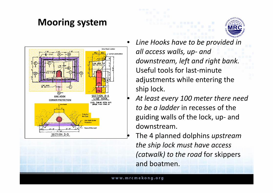
• Line Hooks have to be provided in all access walls, up‐ and downstream, left and right bank. Useful tools for last‐minute adjustments while entering the ship lock.
• At least every 100 meter there need to be a ladder in recesses of the guiding walls of the lock, up‐ and downstream.
• The 4 planned dolphins upstream the ship lock must have access (catwalk) to the road for skippers and boatmen.
Mooring system

• There is no control house on the lock platform
• There is no upstream apron
• The grouting screen should be at the deepest point and double: one upstream, one downstream;
• The access bridge over the lock chamber should respect the 15.00m air clearance and has to be lifted by approx. 3 m
• Possible danger for seepage;
• Possible danger for piping if there are dispersive soils in the subsoil;
The ship lock equipment


The proposed navigation lock does not comply with the recommendations for a double lift lock for heads greater than 30m in the PDG.
Alignment with the PDG

• Redesign the ship lock from single lift to tandem lockwith 2 x 16.19m lift);
• Redesign both of the access and approach channels, especially the downstream approach with the embankment to be excavated with considering the second lock‐design;
• Complete the lock equipment with the suggestions in the report: amongst others: additional ladders in the approach walls, line hooks, upstream apron, grouting screen, etc.;
• Complete the lock with a control house;• Lift the service bridge over the lock by approx. 3 m.;• Redesign he access road to the lock platform;• Prepare the list of required spare parts to be delivered.
Recommendations

25
Thank you!
Recommended