TECHNO Full-Flanged Check ValvesLightweight, seatless design provides virtually no pressure loss across the valve, reducing wear and resistance to flow

2
TECHNO — A well-known Brand with Past History and a Brand New Future!
• Techno Corporation of Erie, Pa. founded in 1952
• Inventor of Elastomer Hinge Dual Plate Check Valve
providing for much improved flow at lowest pressure
drops.
• Design first patented on November 20, 1952
• Grew to be one of the largest and most famous
manufacturers of check valves in the United States.
• Acquired by Newflo Corporation on 12/4/1992.
Remained in Erie Pa under same management.
• Mid 1996 Newflo (including Techno Corporation) was
acquired by PCC (Precision Castparts Corporation).
• PCC moved Techno to Milbury, Mass in 1999 combining them with TBV (Titanium Ball Valve Co.) in a
54,000 ft2 facility.
• Techno (along with TBV) was acquired by Cameron International in 2004.
• Techno product line transferred to Cameron Valve and Measurement’s 250,000 ft2 plant in Oklahoma
City in 2010.
• US Valve LLC acquires Techno product line from Cameron in April of 2016.
• We are now entirely focused on producing low pressure drop check valves in our Linthicum, Maryland
facility.
• Lead times are now a priority with > 100,000 parts in stock and options for same day shipment of
most valves.

3
FEATURES
Non-Slam Quick-Closure Feature
The valve plate design reduces travel from fully open to fully closed position and offers complete metal-to-metal valve plate structural support.
Unique Flexible Elastomer Seal
Continuous elastomer seal provides closure around valve bore with the strength and durability to ensure prolonged life cycle, outwearing traditional metal-seated valves.
Design Features
US Valve’s TECHNO™ full-flanged check valves offer the following features:
• For the most efficient piping layout, the check valve can be mounted in almost any position.
• Unrestricted full-port seatless design provides free flowthrough with virtually
no pressure loss.
• The stationary hinge-post and hinge-clamp designs reduce wear to hinges, pins,
valve seats and springs.

4
TECHNO CHECK STYLE 5003, 5003-316, 5004-CIL, 5004-CAL, 5102 AND 5107
Style Body Internals Flange Series Cold Working Pressure (psi)
5003 Carbon Steel 316 Stainless Steel 150 150
5003-316 316 Stainless Steel 316 Stainless Steel 150 150
5004 CIL Cast Iron Lightweight Aluminum 125 50
5004 CAL Cast Aluminum Lightweight Aluminum 125 50
5102 Carbon Steel Aluminum 150 150
5107 Carbon Steel 316 Stainless Steel 300 300
Standard Models and Materials
US Valve’s TECHNO line has been a leading supplier of high-quality check valves to the industry for many years. Thousands of TECHNO products are presently in service, demonstrating a superior performance record.
The TECHNO check design, combined with an extensive
selection of materials, results in high performance and reliability for most liquid or gas applications.
The unique design, combined with years of experience, allows us to excel in some of the most difficult applications.
Style 5003 Style 5004

5
TECHNO CHECK STYLE 5003 WITH 150# RAISED FACE FLANGED ENDS
Optional Materials Selection
Internal Materials
• Aluminum
• 316 Stainless Steel
Sealing Member Materials
MATERIAL TEMPERATURE RANGE*
• Buna-N -60° F to 225° F (-51° C to 107° C)
• EPDM -40° F to 300° F (-40° C to 149° C)
• Viton® -20° F to 400° F (-29° C to 204° C)
• Silicone -100° F to 500° F (-73° C to 260° C)
* This temperature range is for general guidance.
The figures may vary with application.
Spring Material
• 302 Stainless Steel
DIA Holes Equally Spaced OnDIA Bolt Circle A
B DIA
Flow
C
E
D
Valve Size (in.)
A B C D E
1 3 4-1/4 5/8 4 3-1/8
1-1/4 4-1/2 4-5/8 5/8 4 3-1/2
1-1/2 4-1/2 5 5/8 4 3-7/8
2 4-1/2 6 3/4 4 4-3/4
2-1/2 5 7 3/4 4 5-1/2
3 5 7-1/2 3/4 4 6
4 5-1/2 9 3/4 8 7-1/2
5 6 10 7/8 8 8-1/2
6 7 11 7/8 8 9-1/2
8 9 13-1/2 7/8 8 11-3/4
10 11 16 1 12 14-1/4
12 13 19 1 12 17
14 15 21 1-1/8 12 18-3/4
16 17 23-1/2 1-1/8 16 21-1/4
18 19 25 1-1/4 16 22-3/4
20 21 27-1/2 1-1/4 20 25
24 25 32 1-3/8 20 29-1/2
All dimensions are in inches.
General Dimensions for Style 5003
Style Body Internals* Cold Working Pressure (psi)
5003 Steel 316 Stainless Steel 150
5003-316 316 Stainless Steel 316 Stainless Steel 150
Standard Models and Materials
* Standard Elastomer: Buna-N Consult US Valve for materials, sizes and pressure ratings not shown.
6
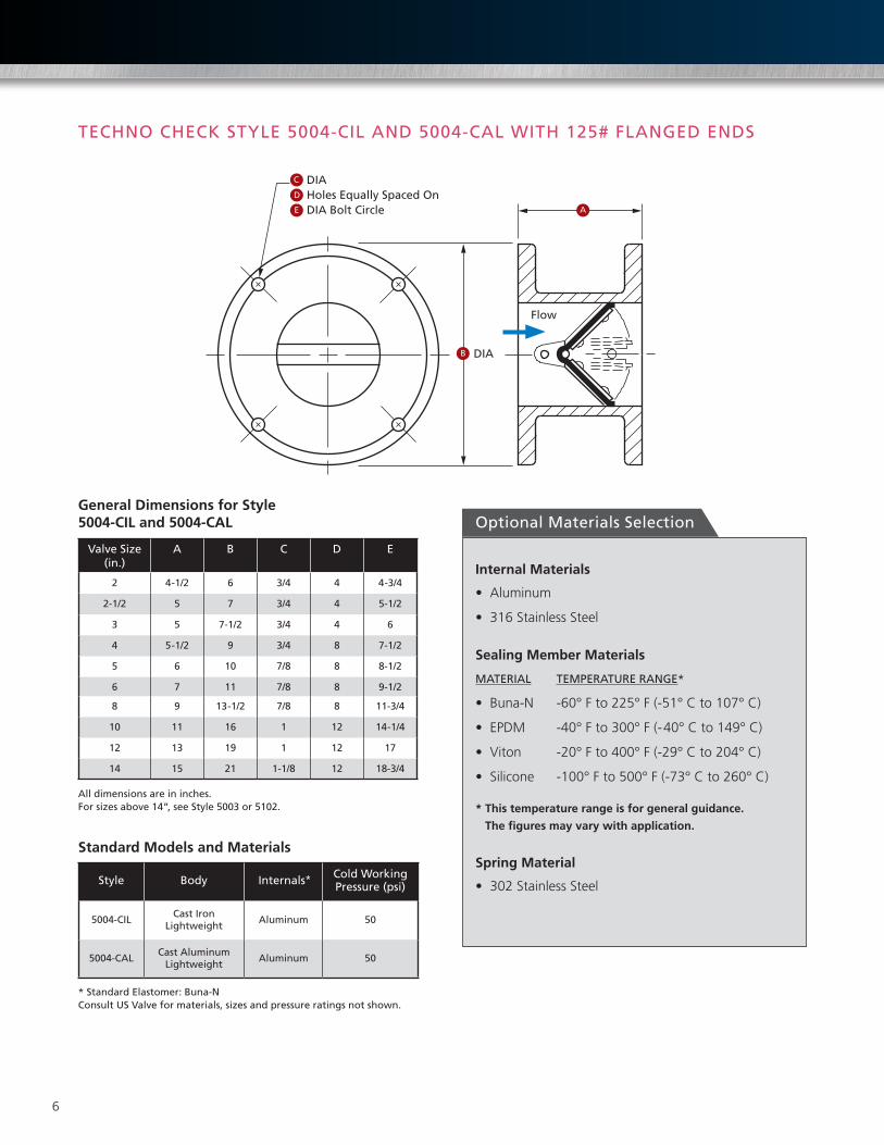
TECHNO CHECK STYLE 5004-CIL AND 5004-CAL WITH 125# FLANGED ENDS
Optional Materials Selection
Internal Materials
• Aluminum
• 316 Stainless Steel
Sealing Member Materials
MATERIAL TEMPERATURE RANGE*
• Buna-N -60° F to 225° F (-51° C to 107° C)
• EPDM -40° F to 300° F (-40° C to 149° C)
• Viton -20° F to 400° F (-29° C to 204° C)
• Silicone -100° F to 500° F (-73° C to 260° C)
* This temperature range is for general guidance.
The figures may vary with application.
Spring Material
• 302 Stainless Steel
DIA Holes Equally Spaced OnDIA Bolt Circle A
B DIA
Flow
C
E
D
Valve Size (in.)
A B C D E
2 4-1/2 6 3/4 4 4-3/4
2-1/2 5 7 3/4 4 5-1/2
3 5 7-1/2 3/4 4 6
4 5-1/2 9 3/4 8 7-1/2
5 6 10 7/8 8 8-1/2
6 7 11 7/8 8 9-1/2
8 9 13-1/2 7/8 8 11-3/4
10 11 16 1 12 14-1/4
12 13 19 1 12 17
14 15 21 1-1/8 12 18-3/4
All dimensions are in inches.For sizes above 14“, see Style 5003 or 5102.
General Dimensions for Style 5004-CIL and 5004-CAL
Style Body Internals* Cold Working Pressure (psi)
5004-CILCast Iron
LightweightAluminum 50
5004-CALCast Aluminum
LightweightAluminum 50
Standard Models and Materials
* Standard Elastomer: Buna-N Consult US Valve for materials, sizes and pressure ratings not shown.

7
TECHNO CHECK STYLE 5102 WITH 150# FLAT FACE FLANGED ENDS
Optional Materials Selection
Internal Materials
• Aluminum
• 316 Stainless Steel
Sealing Member Materials
MATERIAL TEMPERATURE RANGE*
• Buna-N -60° F to 225° F (-51° C to 107° C)
• EPDM -40° F to 300° F (-40° C to 149° C)
• Viton -20° F to 400° F (-29° C to 204° C)
• Silicone -100° F to 500° F (-73° C to 260° C)
* This temperature range is for general guidance.
The figures may vary with application.
Spring Material
• 302 Stainless Steel
Valve Size (in.)
A B C D E
3 5 7 1/2 3/4 4 6
4 5-1/2 9 3/4 8 7-1/2
5 6 10 7/8 8 8-1/2
6 7 11 7/8 8 9-1/2
8 9 13-1/2 7/8 8 11-3/4
10 11 16 1 12 14-1/4
12 13 19 1 12 17
14 15 21 1-1/8 12 18-3/4
16 17 23-1/2 1-1/8 16 21-1/4
18 19 25 1-1/4 16 22-3/4
20 21 27-1/2 1-1/4 20 25
24 25 32 1-3/8 20 29-1/2
All dimensions are in inches.
General Dimensions for Style 5102
Style Body Internals* Cold Working Pressure (psi)
5102 Steel Aluminum 150
Standard Models and Materials
* Standard Elastomer: Buna-N Consult Cameron for materials, sizes and pressure ratings not shown.
DIA Holes Equally Spaced OnDIA Bolt Circle A
B DIA
Flow
C
E
D

8
TECHNO CHECK STYLE 5107 WITH 300# RAISED FACE FLANGED ENDS
Optional Materials Selection
Internal Materials
• Aluminum
• 316 Stainless Steel
Sealing Member Materials
MATERIAL TEMPERATURE RANGE*
• Buna-N -60° F to 225° F (-51° C to 107° C)
• EPDM -40° F to 300° F (-40° C to 149° C)
• Viton -20° F to 400° F (-29° C to 204° C)
• Silicone -100° F to 500° F (-73° C to 260° C)
* This temperature range is for general guidance.
The figures may vary with application.
Spring Material
• 302 Stainless Steel
A
B DIA
Flow
DIA Holes Equally Spaced OnDIA Bolt Circle
C
E
D
Valve Size (in.)
A B C D E
1 4-1/2 4-7/8 3/4 4 3 1/2
1-1/4 4-1/2 5-1/4 3/4 4 3 7/8
1-1/2 5-1/8 6-1/8 7/8 4 4-1/2
2 5-1/8 6-1/2 3/4 8 5
2-1/2 5-5/8 7-1/2 7/8 8 5-7/8
3 6 8-1/4 7/8 8 6-5/8
4 6-5/8 10 7/8 8 7-7/8
5 7-1/4 11 7/8 8 9-1/4
6 8 12-1/2 7/8 12 10-5/8
8 10-1/2 15 1 12 13
10 12-1/2 17-1/2 1-1/8 16 15-1/4
12 14-1/2 20-1/2 1-1/4 16 17-3/4
14 16-1/2 23 1-1/4 20 20-1/4
16 18-1/2 25-1/2 1-3/8 20 22-1/2
18 20-3/4 28 1-3/8 24 24-3/4
20 24 30-1/2 1-3/8 24 27
24 27 36 1-5/8 24 32
All dimensions are in inches.
General Dimensions for Style 5107
Style Body Internals* Cold Working Pressure (psi)
5107 Steel 316 Stainless Steel 300
5107-316 316 Stainless Steel 316 Stainless Steel 300
Standard Models and Materials
* Standard Elastomer: Buna-N Consult US Valve for materials, sizes and pressure ratings not shown.
9
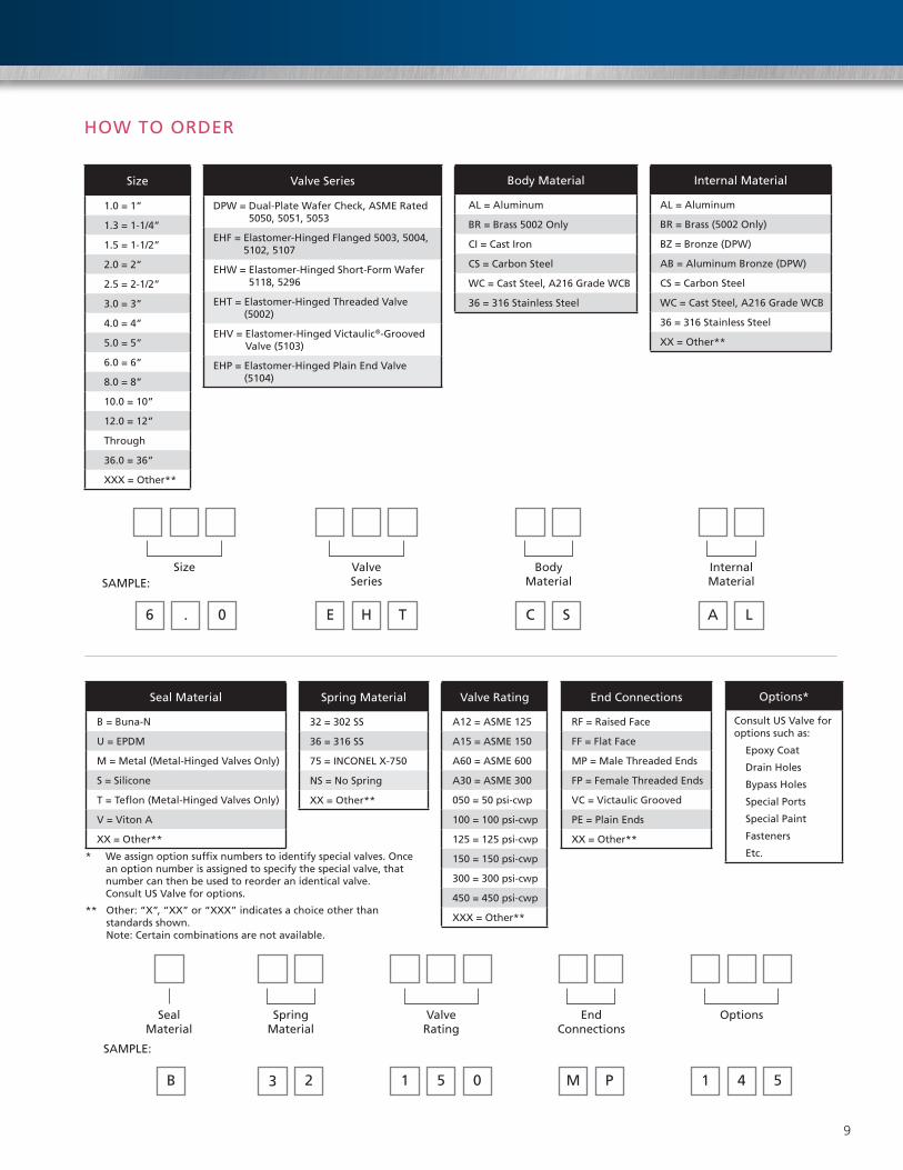
HOW TO ORDER
Size
1.0 = 1”
1.3 = 1-1/4”
1.5 = 1-1/2”
2.0 = 2”
2.5 = 2-1/2”
3.0 = 3”
4.0 = 4”
5.0 = 5”
6.0 = 6”
8.0 = 8”
10.0 = 10”
12.0 = 12”
Through
36.0 = 36”
XXX = Other**
Valve Series
DPW = Dual-Plate Wafer Check, ASME Rated 5050, 5051, 5053
EHF = Elastomer-Hinged Flanged 5003, 5004, 5102, 5107
EHW = Elastomer-Hinged Short-Form Wafer 5118, 5296
EHT = Elastomer-Hinged Threaded Valve (5002)
EHV = Elastomer-Hinged Victaulic®-Grooved Valve (5103)
EHP = Elastomer-Hinged Plain End Valve (5104)
Body Material
AL = Aluminum
BR = Brass 5002 Only
CI = Cast Iron
CS = Carbon Steel
WC = Cast Steel, A216 Grade WCB
36 = 316 Stainless Steel
Internal Material
AL = Aluminum
BR = Brass (5002 Only)
BZ = Bronze (DPW)
AB = Aluminum Bronze (DPW)
CS = Carbon Steel
WC = Cast Steel, A216 Grade WCB
36 = 316 Stainless Steel
XX = Other**
Size Valve Series
Body Material
Internal MaterialSAMPLE:
6 . 0 E H T C S A L
Seal Material
B = Buna-N
U = EPDM
M = Metal (Metal-Hinged Valves Only)
S = Silicone
T = Teflon (Metal-Hinged Valves Only)
V = Viton A
XX = Other**
Spring Material
32 = 302 SS
36 = 316 SS
75 = INCONEL X-750
NS = No Spring
XX = Other**
Valve Rating
A12 = ASME 125
A15 = ASME 150
A60 = ASME 600
A30 = ASME 300
050 = 50 psi-cwp
100 = 100 psi-cwp
125 = 125 psi-cwp
150 = 150 psi-cwp
300 = 300 psi-cwp
450 = 450 psi-cwp
XXX = Other**
End Connections
RF = Raised Face
FF = Flat Face
MP = Male Threaded Ends
FP = Female Threaded Ends
VC = Victaulic Grooved
PE = Plain Ends
XX = Other**
Options*
Consult US Valve for options such as:
Epoxy Coat
Drain Holes
Bypass Holes
Special Ports
Special Paint
Fasteners
Etc.* We assign option suffix numbers to identify special valves. Once an option number is assigned to specify the special valve, that number can then be used to reorder an identical valve. Consult US Valve for options.
** Other: “X”, “XX” or “XXX” indicates a choice other than standards shown. Note: Certain combinations are not available.
Valve Rating
Spring Material
SAMPLE:
B
End Connections
OptionsSeal Material
3 2 1 5 0 M P 1 4 5

10
Exploded View
Techno™ Flow Coefficients (Cv) vs. Conventional DesignsSize Techno
Elastomer HingeConventional
Duo Disc DesignConventional
Swing Check DesignConventional
Lift Check Valve
1 37 — 22 171 1/4 65 — 39 —1 1/2 83 — 55 352 145 75 65 63
2 1/2 350 95 90 1003 590 190 135 1484 920 375 215 2605 1400 480 680 4156 2800 820 1270 6208 4900 1590 2350 103010 7200 2900 3850 163012 9000 4500 4750 237014 11000 5900 7400 350016 13000 8700 9550 510018 15000 10900 13000 640020 28000 14300 22000 770024 39000 23000 — 1110030 58000 37000 — —36 75000 59000 — —
Flow Coefficient Comparisons (Cv) – GPM of water @ 60°F and 1 PSI Pressure Drop. TECHNO is a trademark of US Valve.
Part No. Part Description
1 Flanged Body 2 Wing Support3* Spring Pin3** Wing Pin4 Disc5 Back-up Disc6 Elastomer Seal7 Spring8 Limiter9 WS/LM Fastener10 Sealing Washer11 Internal Fasteners
Note: If valve is supplied with optional spring, use part number 3* (Spring Pin), otherwise use 3** (Wing Pin).
2
3*3**
4
5
6
7
99
1010
11
8
1

11
Pressure Drop Charts for Water and Air Service
Liquid Applications
Gas Applications
2"
1" 3"21/2
"
11/4
"11
/2"
6" 8" 10"
12"
14"
16"
18"
20"
24"
30"
36"
4" 5"
0.1
1.0
10
100
Pres
sure
Los
s in
P.S
.I.
10 50 100
500
1,00
0
5,00
0
10,0
00
50,0
00
100,
000
500,
000
1,00
0,00
0
Water Flow – GPM @ 70°F
2"
1" 3"21/2"
11/2"
11/4"
6"5" 8" 10"
12"
14"
16"
18"
20"
24"
30"
36"
4"
0.01
0.1
1.0
10.0
Pres
sure
Los
s in
P.S
.I.
10 50 100
500
1,00
0
5,00
0
10,0
00
50,0
00
100,
000
500,
000
1,00
0,00
0
Air Flow – SCFM @ 70°F
T: 410.636.3380 F: 410.789.1009
Techno Holdings LLC812E Oregon AvenueLinthicum, MD 21090
Recommended