Template of Stormwater Pollution Prevention Plan (SWPPP)
for the Construction Activities Associated with the
Massachusetts Portion of the Greater Springfield Reliability Project
in
Agawam, Chicopee, Ludlow, Springfield, and West Springfield, Massachusetts
Prepared for: Western Massachusetts Electric Company
Prepared by:
Burns & McDonnell Engineering Company, Inc. Kansas City, Missouri
October 2008
COPYRIGHT©2008 Burns & McDonnell Engineering Company, Inc.

Stormwater Pollution Prevention Plan Table of Contents
Western Massachusetts Electric Company TOC-1 Burns & McDonnell
TABLE OF CONTENTS
Page No.
1.0 INTRODUCTION...............................................................................................1-1 1.1 Project Description and Location.....................................................................................1-2 1.2 Project Owner and Operator ............................................................................................1-5 1.3 Certifications....................................................................................................................1-5 1.4 Standard Permit Conditions .............................................................................................1-6
1.4.1 Duty to Comply with Permit Conditions ........................................................... 1-6 1.4.2 Final Stabilization and Termination of Coverage .............................................. 1-6 1.4.3 Retention of Records ......................................................................................... 1-6
2.0 CONSTRUCTION ACTIVITIES AND SITE DESCRIPTION..............................2-1 2.1 Description of Construction Activities ............................................................................2-1 2.2 Sequence of Major Construction Activities .....................................................................2-1 2.3 Soils .................................................................................................................................2-3 2.4 Potential Pollutants ..........................................................................................................2-6 2.5 Site Maps and Drawings ..................................................................................................2-6 2.6 Receiving Waters .............................................................................................................2-6
3.0 BEST MANAGEMENT PRACTICES ................................................................3-1 3.1 Erosion and Sediment Controls .......................................................................................3-1 3.2 Structural Control Practices .............................................................................................3-1
3.2.1 Temporary Erosion and Sediment Control Practices......................................... 3-2 3.2.1.1 Silt Fence Sediment Barriers ..............................................................3-2 3.2.1.2 Check Dams........................................................................................3-2 3.2.1.3 Wetland Matting.................................................................................3-3
3.2.2 Permanent Erosion and Sediment Control Practices ......................................... 3-3 3.3 Stabilization Practices......................................................................................................3-3 3.4 Maintenance and Inspections...........................................................................................3-3 3.5 Final Stabilization and Cleanup .......................................................................................3-4
3.5.1 Seeding .............................................................................................................. 3-4 3.5.2 Fertilizer............................................................................................................. 3-4 3.5.3 Mulching............................................................................................................ 3-5 3.5.4 Topsoiling .......................................................................................................... 3-5 3.5.5 Removal of Temporary Controls ....................................................................... 3-5
4.0 GOOD HOUSEKEEPING..................................................................................4-1 4.1 Material Handling ............................................................................................................4-1 4.2 Solid and Liquid Waste Disposal.....................................................................................4-1 4.3 Hazardous Waste .............................................................................................................4-1 4.4 Sanitary Waste .................................................................................................................4-1 4.5 Non-Stormwater Discharges............................................................................................4-1 4.6 Vehicle Washing..............................................................................................................4-2 4.7 Water Source....................................................................................................................4-2
5.0 SPILL PREVENTION AND CONTROL PLAN..................................................5-1 5.1 Material Management Practices.......................................................................................5-1
5.1.1 Good Housekeeping........................................................................................... 5-1 5.1.2 Non-Petroleum Products.................................................................................... 5-2 5.1.3 Petroleum Products ............................................................................................ 5-2
5.2 Spill Control and Cleanup................................................................................................5-2
Stormwater Pollution Prevention Plan Table of Contents
Western Massachusetts Electric Company TOC-2 Burns & McDonnell
APPENDICES – Not included for DEIR
Appendix A Erosion Plans Appendix B BMP Details Appendix C Inspections Appendix D Spill Reporting Appendix E NOI Form Appendix F General Permit Appendix G Site Notice Appendix H NOT Form
LIST OF FIGURES
Page No. Figure 1-1 General Vicinity Map.............................................................................................................1-8

Section 1.0 INTRODUCTION

Stormwater Pollution Prevention Plan Introduction
Western Massachusetts Electric Company 1-1 Burns & McDonnell
1.0 INTRODUCTION
The U.S. Environmental Protection Agency (EPA) requires a National Pollutant Discharge Elimination
System (NPDES) General Permit for stormwater discharges from construction sites that disturb more than
one acre of land or from smaller sites that are part of a larger, common plan of development. For the
purposes of the NPDES program, construction activities are defined as clearing, excavating, grading, or
other land disturbing activities.
In the Commonwealth of Massachusetts (Commonwealth), the EPA maintains authority over the NPDES
program. Construction projects issued a certificate of permit coverage under EPA General Permit No.
MAR100000 (Permit) are granted permission to discharge stormwater associated with construction
activities into state waters. The Permit is issued pursuant to the Clean Water Act as amended (33 U.S.C.
1251 et. seq.). A copy of this Permit is located in Appendix F.
Coverage under this Permit is obtained by submitting a Notice of Intent (NOI) at least seven days prior to
initiation of construction activities (a copy of the NOI is located in Appendix E). A Stormwater Pollution
Prevention Plan (SWPPP) must be developed prior to submittal of the NOI. The SWPPP described herein
establishes a plan to manage the quality of stormwater runoff from construction activities associated with
the Greater Springfield Reliability Project (Project) for the Western Massachusetts Electric Company.
This SWPPP has been developed in accordance with requirements and guidelines specified in Part 5 of
the Permit. Stormwater control measures addressed in this SWPPP must also be consistent with
requirements and procedures of state and local control measure and stormwater management plans,
including Volume 2 and 3 of the Massachusetts Stormwater Handbook, which is published by the
Massachusetts Department of Environmental Protection (MassDEP) under the authority of the Wetlands
Protection Act and the Massachusetts Clean Waters Act.
The SWPPP must be revised whenever stormwater control measures are modified due to a change in
design, construction method, operation, maintenance procedure, etc. Best Management Practices (BMPs)
should be moved, added, or redesigned as necessary to control erosion and sedimentation to the maximum
extent practicable.
The SWPPP was written with the assistance of and information from Developing Your Stormwater
Pollution Prevention Plan: A Guide for Construction Sites (EPA, May 2007). This document is a guide
Stormwater Pollution Prevention Plan Introduction
Western Massachusetts Electric Company 1-2 Burns & McDonnell
to be used by the on-site construction personnel to reduce soil erosion and to prevent sediment and
potential on-site pollutants from leaving the site and entering wetlands or waters of the Commonwealth.
1.1 PROJECT DESCRIPTION AND LOCATION The GSRP will establish a new 345-kV/115-kV “hub” west of the Connecticut River at WMECO’s
existing Agawam Substation, where several 115-kV lines from the east, west, north and south presently
connect, including lines which provide a supply point to the Springfield 115-kV system. The new 345-
kV lines, connecting three substations (Ludlow, Agawam and North Bloomfield), will complete a loop
between WMECO’s Ludlow Substation and CL&P’s North Bloomfield Substation, for the purpose of
reinforcing the Springfield area transmission system. The new 345-kV lines proposed by WMECO as the
Preferred Northern Route, will be constructed for 23 miles between WMECO’s Ludlow Substation in
Ludlow and the Connecticut/Massachusetts border in Agawam, Massachusetts. Interconnected facilities
in Connecticut will be constructed for 12 miles from the border with Massachusetts to the North
Bloomfield Substation in Bloomfield, Connecticut. Substation and switching station modifications are
also required in connection with the transmission line construction. Modifications will affect the Ludlow,
Agawam, Chicopee, Orchard, Breckwood and Piper Substations, and the Shawinigan and South Agawam
Switching Stations. In addition, in order to accommodate the new and updated transmission lines,
WMECO will re-build its existing Fairmont Switching Station and will construct a new 115-kV switching
station, to be called the Cadwell Switching Station, at WMECO’s East Springfield Service Center.
Upgrades to existing 115-kV transmission lines, which will occur primarily along the same route as the
proposed new Massachusetts 345-kV lines, will also be made to handle anticipated flows through the
system. In addition, approximately four miles of 115-kV transmission line upgrades will occur along
existing “spurs” or ROWs which intersect the Preferred Northern Route in three locations: Orchard
Junction, Exit 6 Junction and East Springfield Junction. All of the 115-kV upgrades are being planned,
and will be constructed with the new 345-kV lines, as integrated parts of a single transmission project.
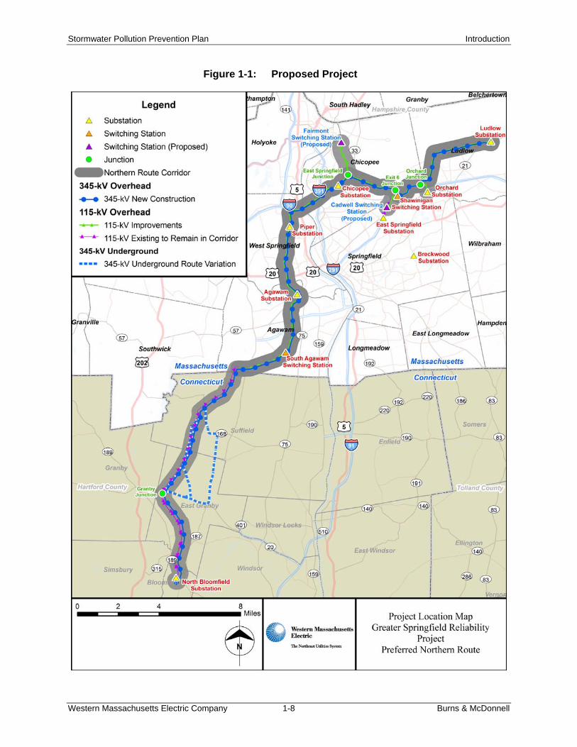
Figure 1-1 is a map which shows the proposed improvements, including the switching stations and
substations, and their location in the Greater Springfield area.
The Project will consist of the following components:
345-kV Facilities
o Modify the 345-kV switchyard at the Ludlow Substation to connect the new Ludlow –
Agawam 345-kV circuit, reconnect the existing 345-kV Ludlow – Carpenter Hill 301
circuit, reconnect the existing 345-kV Ludlow – Barbour Hill 3419 circuit, replace the
Stormwater Pollution Prevention Plan Introduction
Western Massachusetts Electric Company 1-3 Burns & McDonnell
existing two 345/115-kV, three-phase 600-MVA autotransformers with two new standard
345/115-kV, 600-MVA autotransformers (each employing three single-phase 200-MVA
units), and install two new 345-kV 120-MVAR capacitor banks.
o Build a new 345-kV switchyard at the existing Agawam Substation to connect the new
345-kV Ludlow – Agawam circuit, the new 345-kV Agawam to North Bloomfield
(Connecticut) circuit and two new 345/115-kV, 600-MVA autotransformers.
o Build a new 345-kV circuit from Ludlow Substation to Agawam Substation, for
approximately 16.7 miles, using two 1590 kcmil ACSR conductors per phase.
o Build a new 345-kV circuit from Agawam Substation to the North Bloomfield
(Connecticut) Substation, for approximately 18.0 miles (approximately 6.0 miles of
which is in Massachusetts), using two 1590 kcmil ACSR conductors per phase.
115-kV Facilities
o Re-build the existing 115-kV Fairmont Switching Station at a nearby site to connect the
existing circuits interconnecting at the station and the two additional 115-kV circuit
segments from East Springfield Junction.
o Build a new 115-kV switching station in the vicinity of the East Springfield Substation
(Cadwell). The new Cadwell Switching Station will interconnect the 115-kV 1481, 1426,
1603, 5001 and 5002 circuits.
o Re-build the 115-kV Ludlow – Shawinigan 1845 circuit, for approximately 6.2 miles,
using two 1272-kcmil ACSR conductors per phase. This 115-kV circuit will share
double-circuit structures with the new 345-kV Ludlow – Agawam circuit.
o Re-build the 115-kV Ludlow – Cadwell (formally East Springfield) 1481 circuit, for
approximately 7.3 miles, using two 795-kcmil ACSR conductors per phase. Where
parallel, the 1481 and 1552 circuits will share double-circuit monopole structures, as will
the 1481 and 1426 circuits.
o Re-build the 115-kV Ludlow – Orchard 1552 circuit, for approximately 5.5 miles, using a
single 1590-kcmil ACSR conductor per phase. Where parallel, the 1481 and 1552
circuits will share double-circuit monopole structures.
o Re-build the 115-kV Orchard – Cadwell (formally East Springfield) 1426 circuit, for
approximately 3.2 miles, using a single 1272-kcmil ACSR conductor per phase. Where
parallel, the 1481 and 1426 circuits will share double-circuit monopole structures.
o Re-build the 115-kV Shawinigan – Fairmont portions of the former 1254 circuit (to be
designated circuit 1604), for approximately 5.0 miles, using two 1590-kcmil ACSR
conductors per phase on single-circuit monopole structures.
Stormwater Pollution Prevention Plan Introduction
Western Massachusetts Electric Company 1-4 Burns & McDonnell
o Re-build the 115-kV Cadwell (formally East Springfield) – Fairmont portions of the
former 1723 circuit (to be designated circuit 1603), for approximately 5.3 miles, using
two 1272-kcmil ACSR conductors per phase. The re-built circuit will share double-
circuit structures with the new 345-kV Ludlow – Agawam circuit east of East Springfield
Junction and with the 115-kV Fairmont to Chicopee 1602 circuit north of East
Springfield Junction.
o Re-build the 115-kV Fairmont – Chicopee portions of the former 1254 circuit (to be
designated circuit 1602), for approximately 2.4 miles, using a single 1272-kcmil ACSR
conductor per phase. The re-built circuit will share double-circuit structures with the new
345-kV Ludlow – Agawam circuit west of East Springfield Junction and with the 115-kV
Fairmont – Cadwell 1603 circuit north of East Springfield Junction
o Re-build the 115-kV Fairmont – Piper portions of the former 1723 circuit (to be
designated circuit 1601), for approximately 5.9 miles, using a single 1590-kcmil ACSR
conductor per phase on single-circuit monopole structures. An outcome of the above-
described re-building of 115-kV circuits to Fairmont will be three monopole lines
supporting sections of four two-terminal 115-kV circuits (1601, 1602, 1603 and 1604)
between East Springfield Junction and Fairmont Switching Station. The 1602 and 1603
lines will share a common double-circuit monopole structure in this section.
o Re-build the 115-kV Piper – Agawam 1230 circuit, for approximately 3.6 miles, using a
single 1590-kcmil ACSR conductor per phase. The circuit will be constructed on single-
circuit monopole structures.
o Re-build the 115-kV Chicopee – Agawam 1314 circuit, for approximately 7.1 miles,
using a single 1272-kcmil ACSR conductor per phase. The circuit will share double-
circuit monopole structures with the new 345-kV Ludlow – Agawam circuit.
o Re-build the 115-kV Agawam – Silver – South Agawam 1782 circuit, for approximately
3.0 miles, using a single 1272-kcmil ACSR conductor per phase on single-circuit
monopole structures.
o Re-build the 115-kV Agawam – Silver – South Agawam 1781 circuit, for approximately
3.0 miles, using a single 1272-kcmil ACSR conductor per phase. The circuit will share
double-circuit monopole structures with the new 345-kV Agawam – North Bloomfield
circuit.
o Re-configure the existing 115-kV transmission system between the South Agawam
Switching Station and the Southwick Substation in western Massachusetts, forming a
Stormwater Pollution Prevention Plan Introduction
Western Massachusetts Electric Company 1-5 Burns & McDonnell
single South Agawam to Southwick 115-kV circuit 1768 with no connections to North
Bloomfield Substation.
o Re-build the Agawam portion of the new 115-kV Southwick – South Agawam 1768
circuit, for approximately 2.5 miles, using a single 1590-kcmil ACSR conductor per
phase. This portion of the circuit will share double-circuit monopole structures with the
new 345-kV Agawam to North Bloomfield circuit.
o Utilize the existing 115-kV line sections, for approximately 0.6 miles, between the new
Cadwell Switching Station and the East Springfield Substation for two new Cadwell to
East Springfield circuits. The new 115-kV 5001 circuit will utilize two 336-kcmil ACSR
conductors per phase, and the new 115-kV 5002 circuit will utilize a single 1113-kcmil
ACSR conductor per phase.
o Leave normally open a 115-kV bus-tie circuit breaker at the Breckwood Substation to
split the substation and install a circuit switcher to normally bypass the existing series
reactor on the 1322 circuit. A portion of the distribution load served by Breckwood
Substation will be fed radially by the 115-kV underground cable 1322 circuit from the
East Springfield Substation. The other portion of the distribution load will be fed radially
by the 115-kV underground 1433 circuit from the West Springfield Substation. The open
bus-tie breaker will automatically close upon and during the outage of either 115-kV
circuit.
o Replace limiting circuit breakers and terminal equipment at the Agawam, Ludlow, and at
Shawinigan Switching Station.
1.2 PROJECT OWNER AND OPERATOR The Project owner and operator, Western Massachusetts Electric Company, will be the responsible entity
for completing the Project. Their address and telephone number are:
Western Massachusetts Electric Company 174 Brush Hill Avenue West Springfield, MA 01090-2010 413-785-5871
1.3 CERTIFICATIONS By signing the Contractors’ Certification Form (located near the front of this document, copy as needed),
each contractor and subcontractor signifies that they have read, understand, and will adhere to the SWPPP
before conducting any construction work that will result in a land disturbance. The signed certification
Stormwater Pollution Prevention Plan Introduction
Western Massachusetts Electric Company 1-6 Burns & McDonnell
confirms that the permittee has notified the contractor or subcontractor that a SWPPP has been prepared
for the Project and that they will perform the necessary actions that have been identified to comply with
the SWPPP and the Permit. It may be necessary for the contractor to implement additional erosion
control and pollution prevention measures that may not be indicated in this SWPPP to maintain
compliance with the Permit.
1.4 STANDARD PERMIT CONDITIONS This section discusses federal penalties for non-compliance with the Permit, as well as standard Permit
conditions. The staff responsible for implementation of the SWPPP will be familiar with the
requirements of the SWPPP and the Permit.
1.4.1 Duty to Comply with Permit Conditions Issues regarding non-compliance with the Permit are overseen by the MassDEP. The permittee has a duty
to comply with all Permit conditions as well as the Massachusetts Surface water Quality Standards (314
CMR 4.00) and the Massachusetts Clean Waters Act. Failure to comply with any Permit condition is a
violation of the Clean Water Act and is grounds for enforcement action including fines, imprisonment,
denial of Permit renewal application, revocation and reissuance, modification, or termination of coverage
under this Permit.
1.4.2 Final Stabilization and Termination of Coverage Final stabilization has been achieved when all soil disturbing activities at the site have been completed
and a uniform (e.g., evenly distributed, without large bare areas) perennial vegetative cover with a density
of 70 percent of the native background vegetative cover for the area has been established on all unpaved
areas. For those areas not covered by permanent structures, an equivalent permanent stabilization
measure (such as the use of rip-rap, gabions, or geotextiles) will be employed. When all construction
activities authorized by this Permit are complete and the site has achieved final stabilization, Permit
coverage must be terminated. Permit coverage is terminated by submitting a Notice of Termination
(NOT) to the EPA with 30 days after cessation of construction activities and final stabilization. A copy of
the NOT form is included in Appendix H.
1.4.3 Retention of Records The SWPPP will be maintained at the appropriate Project construction office from the date of Project
initiation to the date of Project completion. Records will be maintained for dates when major grading
occurs, construction activities temporarily or permanently cease, stabilization measures are initiated, and
final stabilization is achieved (Record Log, Appendix C). The owner will retain the SWPPP for a
Stormwater Pollution Prevention Plan Introduction
Western Massachusetts Electric Company 1-7 Burns & McDonnell
minimum period of three years from the Permit expiration or termination date. Records that must be
retained include:
The SWPPP and any amendments to the SWPPP A copy of the Permit, the signed and certified NOI submitted to EPA, and a copy of the letter
from the EPA’s Stormwater Notice Processing Center indicating that a complete NOI has been received
All reports and actions required by this Permit, including a copy of the Construction Site Notice (Appendix G)
All data used to complete the NOI All site inspection records All contractor’s certifications Any clearance letters, from the U.S. Fish and Wildlife Service (FWS), Massachusetts Division of
Fisheries and Wildlife (MDFW), Massachusetts Historical Commission (MHC), the U.S. Army Corps of Engineers (Corps), or any other agency providing clearance
A copy of the NOT submitted to the EPA
Stormwater Pollution Prevention Plan Introduction
Western Massachusetts Electric Company 1-8 Burns & McDonnell
Figure 1-1: Proposed Project
Section 2.0 CONSTRUCTION ACTIVITIES AND SITE DESCRIPTION

Stormwater Pollution Prevention Plan Construction Activities And Site Description
Western Massachusetts Electric Company 2-1 Burns & McDonnell
2.0 CONSTRUCTION ACTIVITIES AND SITE DESCRIPTION
2.1 DESCRIPTION OF CONSTRUCTION ACTIVITIES
2.2 SEQUENCE OF MAJOR CONSTRUCTION ACTIVITIES Prior to the commencement of construction, WMECO will complete pre-construction planning activities.
In particular, WMECO will continue to consult with the municipalities, state agencies and federal
agencies, and will conduct site-specific studies and surveys in order to design construction procedures for
contractors that will minimize or avoid adverse effects to the environment and to the public. WMECO
will construct the Project in several stages, some of which will overlap in time. During actual
construction, certain work activities and sequences may vary, based on factors such as site-specific
conditions, final Project designs, and the requirements of regulatory approvals.
Construction will typically consist of activities such as:
Surveys to stake monumented line of corridor, ROW boundaries, and future structure locations
Identification and marking wetland and watercourse boundaries
Identification and marking areas of cultural resources areas of concern where avoidance or
special procedures are required
Identification and marking sensitive environmental resource areas to be avoided
Establishment of field construction areas and preparation of staging and lay-down areas
Preparation of ROWs (including the installation of erosion and sedimentation controls,
removal of vegetation as needed, access road improvement/installation)
Preparation of work areas (pads) at structure sites
Excavation and installation of foundations and erection of new structures
Installation of conductors and wires
Removal of existing transmission line structures and associated conductors and wires
Clean-up and restoration, including re-vegetation of disturbed sites
The following construction activities, materials, and equipment are generally expected to be involved in
the construction of the overhead transmission lines on or adjacent to the existing or expanded
transmission ROWs:
Stormwater Pollution Prevention Plan Construction Activities And Site Description
Western Massachusetts Electric Company 2-2 Burns & McDonnell
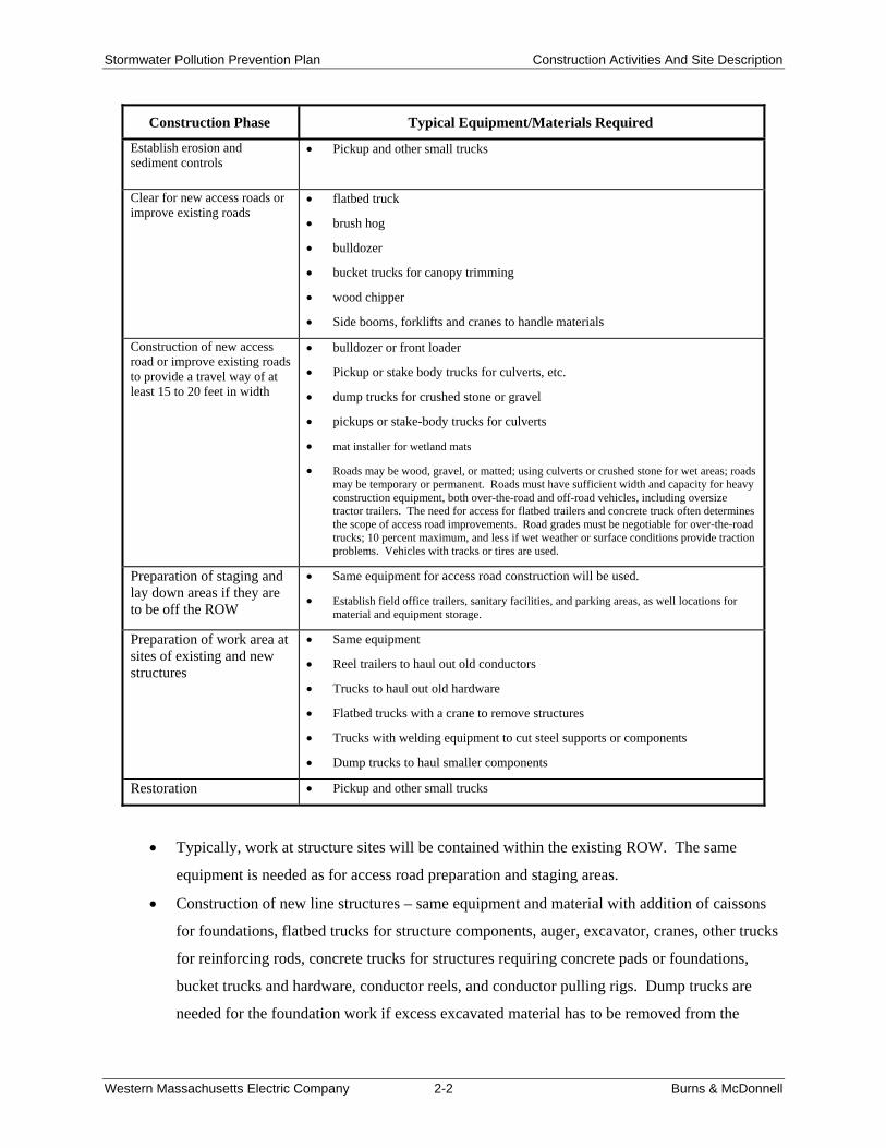
Construction Phase Typical Equipment/Materials Required
Establish erosion and sediment controls
Pickup and other small trucks
Clear for new access roads or improve existing roads
flatbed truck
brush hog
bulldozer
bucket trucks for canopy trimming
wood chipper
Side booms, forklifts and cranes to handle materials
Construction of new access road or improve existing roads to provide a travel way of at least 15 to 20 feet in width
bulldozer or front loader
Pickup or stake body trucks for culverts, etc.
dump trucks for crushed stone or gravel
pickups or stake-body trucks for culverts
mat installer for wetland mats
Roads may be wood, gravel, or matted; using culverts or crushed stone for wet areas; roads may be temporary or permanent. Roads must have sufficient width and capacity for heavy construction equipment, both over-the-road and off-road vehicles, including oversize tractor trailers. The need for access for flatbed trailers and concrete truck often determines the scope of access road improvements. Road grades must be negotiable for over-the-road trucks; 10 percent maximum, and less if wet weather or surface conditions provide traction problems. Vehicles with tracks or tires are used.
Preparation of staging and lay down areas if they are to be off the ROW
Same equipment for access road construction will be used.
Establish field office trailers, sanitary facilities, and parking areas, as well locations for material and equipment storage.
Preparation of work area at sites of existing and new structures
Same equipment
Reel trailers to haul out old conductors
Trucks to haul out old hardware
Flatbed trucks with a crane to remove structures
Trucks with welding equipment to cut steel supports or components
Dump trucks to haul smaller components
Restoration Pickup and other small trucks
Typically, work at structure sites will be contained within the existing ROW. The same
equipment is needed as for access road preparation and staging areas.
Construction of new line structures – same equipment and material with addition of caissons
for foundations, flatbed trucks for structure components, auger, excavator, cranes, other trucks
for reinforcing rods, concrete trucks for structures requiring concrete pads or foundations,
bucket trucks and hardware, conductor reels, and conductor pulling rigs. Dump trucks are
needed for the foundation work if excess excavated material has to be removed from the
Stormwater Pollution Prevention Plan Construction Activities And Site Description
Western Massachusetts Electric Company 2-3 Burns & McDonnell
ROW. In wet conditions or if groundwater is encountered, the water is pumped to a temporary
settling basin with erosion and sedimentation controls including geotextile fabric, silt fence,
hay bales and crushed stone. As with all other activities, this would require EFSB approval
and would have to comply with any applicable regulation.
Removal of existing line structures – bucket trucks for dismantling existing lines, with reel
trailers to capture and store old conductors, trucks to remove old hardware, flatbed truck with
crane to remove structures, trucks with welding equipment to cut steel supports or
components, stake or dump trucks to remove smaller components.
Restoration – all debris is to be removed from the ROW for disposal; but brush may be piled,
scattered, or chipped. Disturbed ground is back bladed to its preconstruction contours unless
directed otherwise. If the work site is in an agricultural field, the soil can be decompacted by
disking. Erosion controls are left in place until vegetation is established. Steep areas are
stabilized with jute netting or pre-made erosion control fabric containing seed, mulch, and
fertilizer. Access roads where culverts or crushed stone fords were installed will be left in
place or removed as directed by the regulatory authorities in accordance with permit/certificate
conditions.
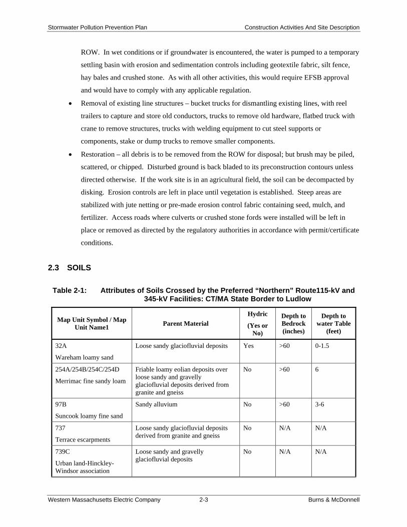
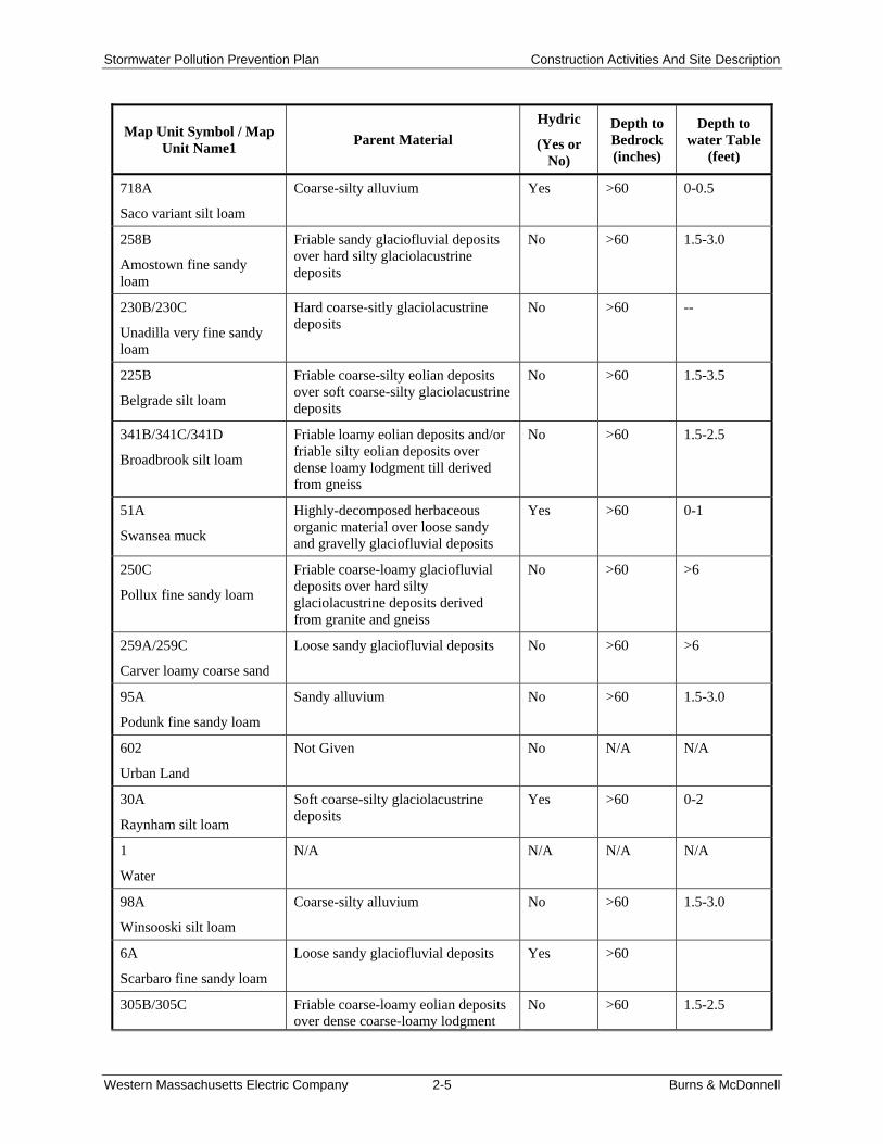
2.3 SOILS
Table 2-1: Attributes of Soils Crossed by the Preferred “Northern” Route115-kV and 345-kV Facilities: CT/MA State Border to Ludlow
Map Unit Symbol / Map Unit Name1
Parent Material
Hydric
(Yes or No)
Depth to Bedrock (inches)
Depth to water Table
(feet)
32A
Wareham loamy sand
Loose sandy glaciofluvial deposits Yes >60 0-1.5
254A/254B/254C/254D
Merrimac fine sandy loam
Friable loamy eolian deposits over loose sandy and gravelly glaciofluvial deposits derived from granite and gneiss
No >60 6
97B
Suncook loamy fine sand
Sandy alluvium No >60 3-6
737
Terrace escarpments
Loose sandy glaciofluvial deposits derived from granite and gneiss
No N/A N/A
739C
Urban land-Hinckley-Windsor association
Loose sandy and gravelly glaciofluvial deposits
No N/A N/A

Stormwater Pollution Prevention Plan Construction Activities And Site Description
Western Massachusetts Electric Company 2-4 Burns & McDonnell
Map Unit Symbol / Map Unit Name1
Parent Material
Hydric
(Yes or No)
Depth to Bedrock (inches)
Depth to water Table
(feet)
740D
Urban land-Wethersfield-Paxton association
Friable coarse-loamy eolian deposits over dense coarse-loamy basal till derived from sandstone and shale.
No 20-36 1.5-2.5
52A
Freetown muck
Highly decomposed herbaceous organic material
Yes >60 0-1
256A
Deerfield loamy fine sand
Loose sandy glaciofluvial deposits No >60 1.5-3
275A/275B
Agawam fine sandy loam
Friable course-loamy eolian deposits over loose sandy glaciofluvial deposits derived from granite and gneiss
No >60 6
260B
Sudbury fine sandy loam
Friable loamy eolian deposits over loose sandy glaciofluvial deposits
No >60 1.5-3
310B
Woodbridge fine sandy loam
Friable coarse-loamy eolian deposits over dense coarse-loamy lodgment till derived from granite and gneiss
No 18-36 1.5-2.5
311B/311C/312B
Woodbridge fine sandy loam
Friable course-loamy eolian deposits over dense coarse-loamy lodgment till derived from granite and gneiss
No >60 1.5-2.5
327D
Meckesville loam
Friable fine-loamy eolian deposits over dense silty lodgment till derived from sandstone and shale
No 18-30 2.5-3.0
417C
Narragansett very fine sandy loam
Friable silty eolian deposits and/or friable loamy eolian deposits over loose sandy glaciofluvial deposits derived from granite and gneiss and/or friable sandy basal till derived from granite and gneiss
No >60 >6
600
Pits, gravel
Loose sandy and gravelly glaciofluvial deposits derived from granite and gneiss
No N/A N/A
253C
Hinckley loamy sand
Loose sandy and gravelly glaciofluvial deposits
No >60 >6
255A/255B/255C/255D/255E
Windsor loamy sand
Loose sandy glaciofluvial deposits No >60 >6
731A
Enosburg loamy sand
Friable sandy glaciofluvial deposits over soft loamy glaciolacustrine deposits
Yes >60 0-1
Stormwater Pollution Prevention Plan Construction Activities And Site Description
Western Massachusetts Electric Company 2-5 Burns & McDonnell
Map Unit Symbol / Map Unit Name1
Parent Material
Hydric
(Yes or No)
Depth to Bedrock (inches)
Depth to water Table
(feet)
718A
Saco variant silt loam
Coarse-silty alluvium Yes >60 0-0.5
258B
Amostown fine sandy loam
Friable sandy glaciofluvial deposits over hard silty glaciolacustrine deposits
No >60 1.5-3.0
230B/230C
Unadilla very fine sandy loam
Hard coarse-sitly glaciolacustrine deposits
No >60 --
225B
Belgrade silt loam
Friable coarse-silty eolian deposits over soft coarse-silty glaciolacustrine deposits
No >60 1.5-3.5
341B/341C/341D
Broadbrook silt loam
Friable loamy eolian deposits and/or friable silty eolian deposits over dense loamy lodgment till derived from gneiss
No >60 1.5-2.5
51A
Swansea muck
Highly-decomposed herbaceous organic material over loose sandy and gravelly glaciofluvial deposits
Yes >60 0-1
250C
Pollux fine sandy loam
Friable coarse-loamy glaciofluvial deposits over hard silty glaciolacustrine deposits derived from granite and gneiss
No >60 >6
259A/259C
Carver loamy coarse sand
Loose sandy glaciofluvial deposits No >60 >6
95A
Podunk fine sandy loam
Sandy alluvium No >60 1.5-3.0
602
Urban Land
Not Given No N/A N/A
30A
Raynham silt loam
Soft coarse-silty glaciolacustrine deposits
Yes >60 0-2
1
Water
N/A N/A N/A N/A
98A
Winsooski silt loam
Coarse-silty alluvium No >60 1.5-3.0
6A
Scarbaro fine sandy loam
Loose sandy glaciofluvial deposits Yes >60
305B/305C Friable coarse-loamy eolian deposits over dense coarse-loamy lodgment
No >60 1.5-2.5
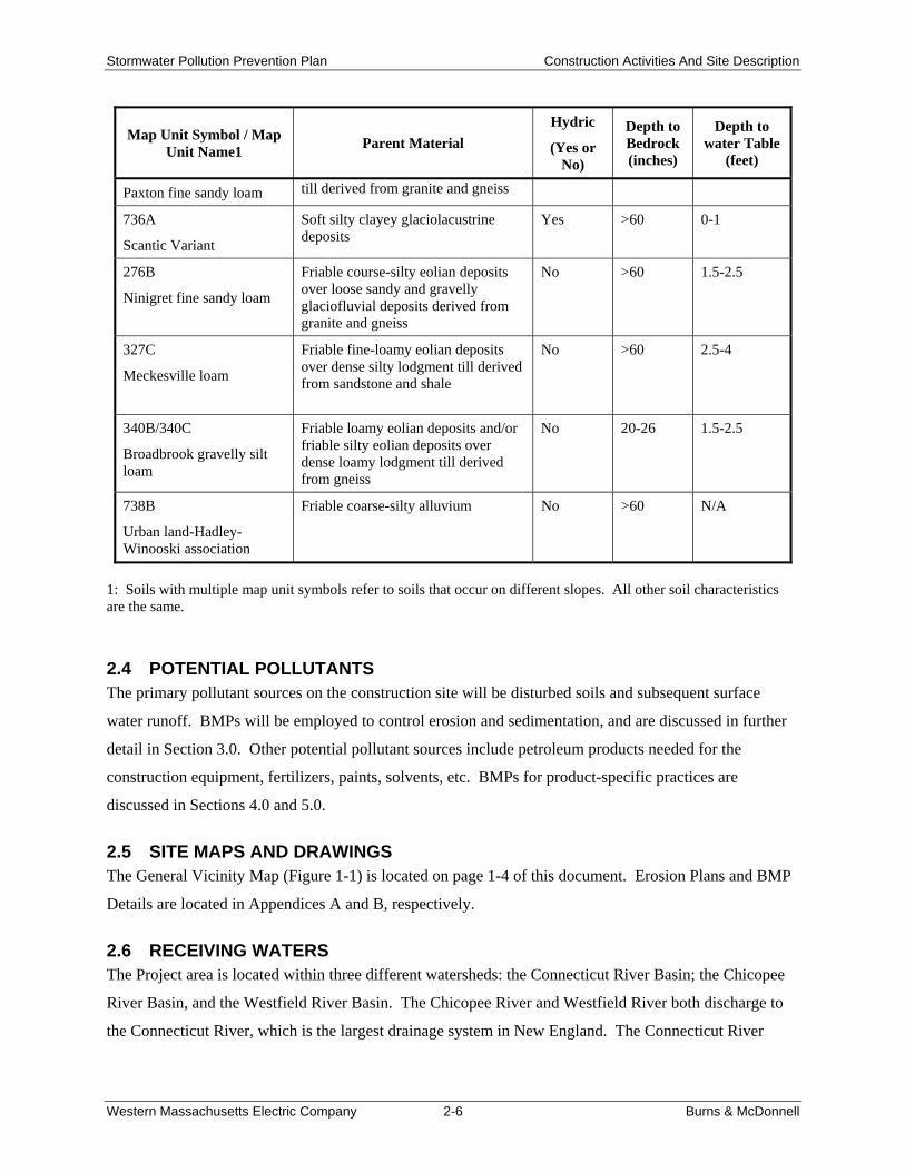
Stormwater Pollution Prevention Plan Construction Activities And Site Description
Western Massachusetts Electric Company 2-6 Burns & McDonnell
Map Unit Symbol / Map Unit Name1
Parent Material
Hydric
(Yes or No)
Depth to Bedrock (inches)
Depth to water Table
(feet)
Paxton fine sandy loam till derived from granite and gneiss
736A
Scantic Variant
Soft silty clayey glaciolacustrine deposits
Yes >60 0-1
276B
Ninigret fine sandy loam
Friable course-silty eolian deposits over loose sandy and gravelly glaciofluvial deposits derived from granite and gneiss
No >60 1.5-2.5
327C
Meckesville loam
Friable fine-loamy eolian deposits over dense silty lodgment till derived from sandstone and shale
No >60 2.5-4
340B/340C
Broadbrook gravelly silt loam
Friable loamy eolian deposits and/or friable silty eolian deposits over dense loamy lodgment till derived from gneiss
No 20-26 1.5-2.5
738B
Urban land-Hadley-Winooski association
Friable coarse-silty alluvium No >60 N/A
1: Soils with multiple map unit symbols refer to soils that occur on different slopes. All other soil characteristics are the same.
2.4 POTENTIAL POLLUTANTS The primary pollutant sources on the construction site will be disturbed soils and subsequent surface
water runoff. BMPs will be employed to control erosion and sedimentation, and are discussed in further
detail in Section 3.0. Other potential pollutant sources include petroleum products needed for the
construction equipment, fertilizers, paints, solvents, etc. BMPs for product-specific practices are
discussed in Sections 4.0 and 5.0.
2.5 SITE MAPS AND DRAWINGS The General Vicinity Map (Figure 1-1) is located on page 1-4 of this document. Erosion Plans and BMP
Details are located in Appendices A and B, respectively.
2.6 RECEIVING WATERS The Project area is located within three different watersheds: the Connecticut River Basin; the Chicopee
River Basin, and the Westfield River Basin. The Chicopee River and Westfield River both discharge to
the Connecticut River, which is the largest drainage system in New England. The Connecticut River
Stormwater Pollution Prevention Plan Construction Activities And Site Description
Western Massachusetts Electric Company 2-7 Burns & McDonnell
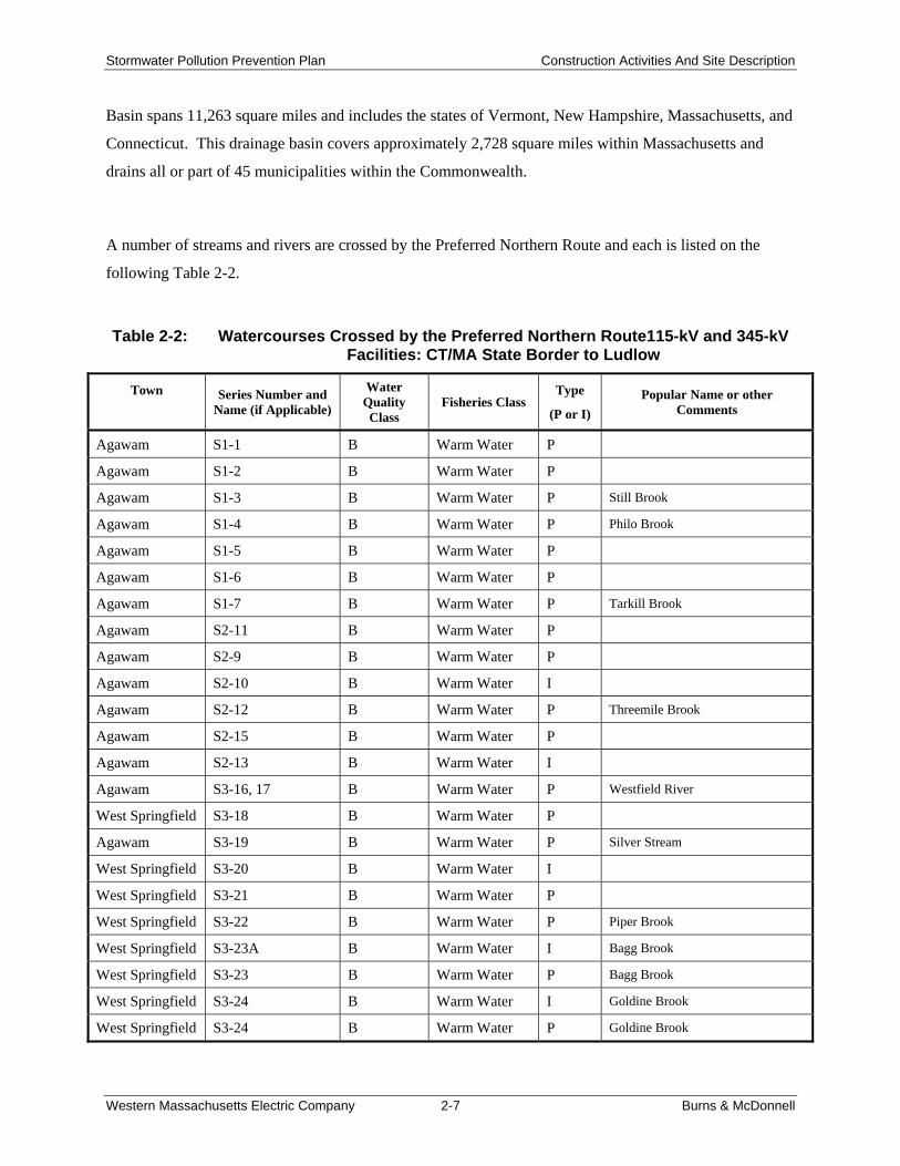
Basin spans 11,263 square miles and includes the states of Vermont, New Hampshire, Massachusetts, and
Connecticut. This drainage basin covers approximately 2,728 square miles within Massachusetts and
drains all or part of 45 municipalities within the Commonwealth.
A number of streams and rivers are crossed by the Preferred Northern Route and each is listed on the
following Table 2-2.
Table 2-2: Watercourses Crossed by the Preferred Northern Route115-kV and 345-kV Facilities: CT/MA State Border to Ludlow
Town
Series Number and Name (if Applicable)
Water Quality Class
Fisheries Class Type
(P or I)
Popular Name or other Comments
Agawam S1-1 B Warm Water P
Agawam S1-2 B Warm Water P
Agawam S1-3 B Warm Water P Still Brook
Agawam S1-4 B Warm Water P Philo Brook
Agawam S1-5 B Warm Water P
Agawam S1-6 B Warm Water P
Agawam S1-7 B Warm Water P Tarkill Brook
Agawam S2-11 B Warm Water P
Agawam S2-9 B Warm Water P
Agawam S2-10 B Warm Water I
Agawam S2-12 B Warm Water P Threemile Brook
Agawam S2-15 B Warm Water P
Agawam S2-13 B Warm Water I
Agawam S3-16, 17 B Warm Water P Westfield River
West Springfield S3-18 B Warm Water P
Agawam S3-19 B Warm Water P Silver Stream
West Springfield S3-20 B Warm Water I
West Springfield S3-21 B Warm Water P
West Springfield S3-22 B Warm Water P Piper Brook
West Springfield S3-23A B Warm Water I Bagg Brook
West Springfield S3-23 B Warm Water P Bagg Brook
West Springfield S3-24 B Warm Water I Goldine Brook
West Springfield S3-24 B Warm Water P Goldine Brook
Stormwater Pollution Prevention Plan Construction Activities And Site Description
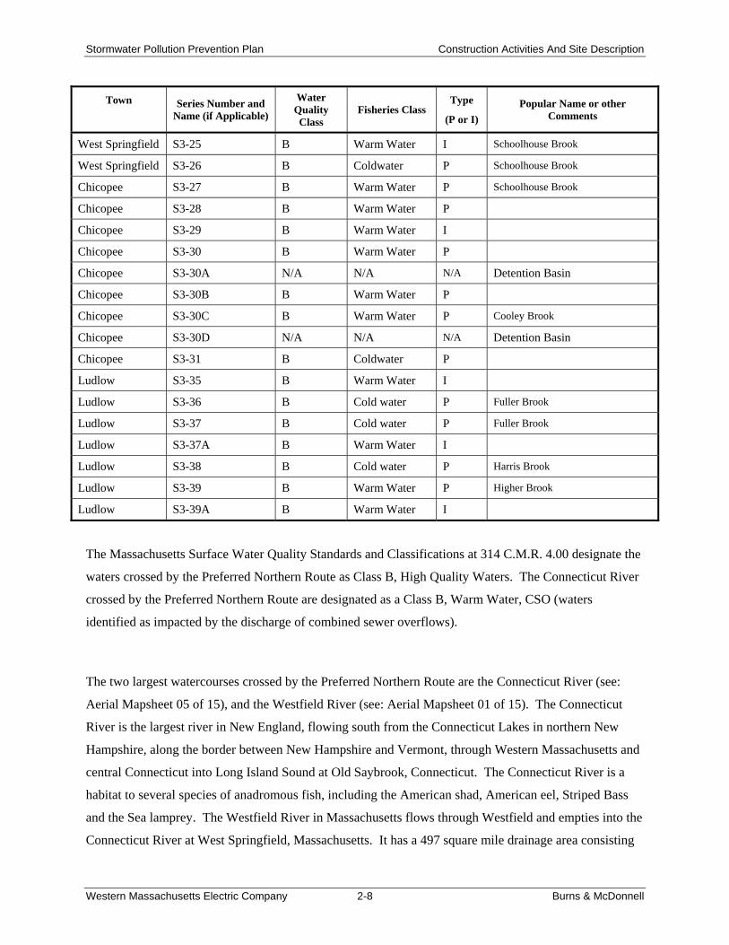
Western Massachusetts Electric Company 2-8 Burns & McDonnell
Town
Series Number and Name (if Applicable)
Water Quality Class
Fisheries Class Type
(P or I)
Popular Name or other Comments
West Springfield S3-25 B Warm Water I Schoolhouse Brook
West Springfield S3-26 B Coldwater P Schoolhouse Brook
Chicopee S3-27 B Warm Water P Schoolhouse Brook
Chicopee S3-28 B Warm Water P
Chicopee S3-29 B Warm Water I
Chicopee S3-30 B Warm Water P
Chicopee S3-30A N/A N/A N/A Detention Basin
Chicopee S3-30B B Warm Water P
Chicopee S3-30C B Warm Water P Cooley Brook
Chicopee S3-30D N/A N/A N/A Detention Basin
Chicopee S3-31 B Coldwater P
Ludlow S3-35 B Warm Water I
Ludlow S3-36 B Cold water P Fuller Brook
Ludlow S3-37 B Cold water P Fuller Brook
Ludlow S3-37A B Warm Water I
Ludlow S3-38 B Cold water P Harris Brook
Ludlow S3-39 B Warm Water P Higher Brook
Ludlow S3-39A B Warm Water I
The Massachusetts Surface Water Quality Standards and Classifications at 314 C.M.R. 4.00 designate the
waters crossed by the Preferred Northern Route as Class B, High Quality Waters. The Connecticut River
crossed by the Preferred Northern Route are designated as a Class B, Warm Water, CSO (waters
identified as impacted by the discharge of combined sewer overflows).
The two largest watercourses crossed by the Preferred Northern Route are the Connecticut River (see:
Aerial Mapsheet 05 of 15), and the Westfield River (see: Aerial Mapsheet 01 of 15). The Connecticut
River is the largest river in New England, flowing south from the Connecticut Lakes in northern New
Hampshire, along the border between New Hampshire and Vermont, through Western Massachusetts and
central Connecticut into Long Island Sound at Old Saybrook, Connecticut. The Connecticut River is a
habitat to several species of anadromous fish, including the American shad, American eel, Striped Bass
and the Sea lamprey. The Westfield River in Massachusetts flows through Westfield and empties into the
Connecticut River at West Springfield, Massachusetts. It has a 497 square mile drainage area consisting
Stormwater Pollution Prevention Plan Construction Activities And Site Description
Western Massachusetts Electric Company 2-9 Burns & McDonnell
of several tributaries. Running for a total of 78.1 miles, the river rises in the Berkshire Hills in the
northwest of the state and flows generally southeastwardly to join the Connecticut River at West
Springfield.
In addition to the rivers described above, the GSRP also crosses perennial streams and intermittent
streams.

Section 3.0 BEST MANAGEMENT PRACTICES

Stormwater Pollution Prevention Plan Best Management Practices
Western Massachusetts Electric Company 3-1 Burns & McDonnell
3.0 BEST MANAGEMENT PRACTICES
3.1 EROSION AND SEDIMENT CONTROLS Soil erosion and sediment controls are measures that are used to reduce the amount of soil particles that
are carried from a land area and deposited in receiving waters. This section provides a general description
of the most appropriate control measures proposed for the Project. The permittee’s construction
contractor(s) and their subcontractors will be responsible for amending the erosion and sediment controls
in the SWPPP for their portion(s) of the Project. Based on field conditions at the time of construction, the
contractors or subcontractors may adjust the locations and types of BMPs so that erosion and
sedimentation are controlled to the maximum extent practicable. However, in no case will modifications
to the SWPPP result in any less stringent erosion and sedimentation control measures than specified
herein. Any revision to the SWPPP will be recorded on the Record of Revisions form; a copy of the form
is located in Appendix C.
Several factors need to be considered when deciding on erosion control techniques. The application of
the techniques in the field will be determined by the professional judgment of the permittee’s field
construction personnel and will depend on site-specific conditions. Factors that may be considered in
selection of erosion and sediment controls for site-specific areas may include:
Size of the area affected Type of proposed construction activities Soil type and texture Amount of rock Steepness and length of slope Amount of vegetative cover Proximity to watercourses or wetlands, particularly downslope from construction activities Date and intensity of the last major rain event Anticipated weather conditions and frozen ground
All applicable soil erosion and sediment control measures will be implemented in accordance with this
SWPPP and the Permit prior to commencement of field construction activities. Measures will be
maintained during and after the construction activity, until final stabilization of the soil is accomplished.
Upon final stabilization of disturbed areas, all temporary soil erosion and sediment control measures will
be removed.
3.2 STRUCTURAL CONTROL PRACTICES Structural control practices divert flows from exposed soils, store water flow, or otherwise limit runoff
from exposed areas of the site. Such practices may include silt fences, earth dikes, drainage swales,
sediment traps, check dams, subsurface drains, pipe slope drains, level spreaders, storm drain inlet
Stormwater Pollution Prevention Plan Best Management Practices
Western Massachusetts Electric Company 3-2 Burns & McDonnell
protection, rock outlet protection (rip-rap), reinforced soil retaining systems, gabions, and temporary or
permanent sediment basins. Some of these practices may be used as both temporary and permanent
control measures. Structural control practices should be placed in upland areas to the degree practicable
to prevent erosion and reduce sedimentation in lower elevation areas.
3.2.1 Temporary Erosion and Sediment Control Practices Erosion and sediment control measures will be in place prior to the initiation of soil disturbing activities
and will be maintained throughout construction. The contractor may need erosion control measures in
other locations of the Project as work progresses to keep sediment from leaving the construction site.
These measures will be determined by the contractor in the field; if measures are changed in the field, the
SWPPP must be modified accordingly. All temporary erosion controls will be removed after the
protected area is finally stabilized. The minimum temporary erosion and sediment control practices that
will be used for the Project are discussed in the following sections.
3.2.1.1 Silt Fence Sediment Barriers Silt fence will be used to intercept and retain sediment carried by sheet flow from disturbed areas and to
prevent sediment runoff from the Project site. Silt fence will be placed perpendicular to the direction of
water flow and as close to the contours as possible with the ends extending upslope. The devices will be
placed downslope of disturbed areas where sheet or rill erosion would occur. Contractors must remove
trapped sediment from a silt fence before the deposit reached 50 percent of the above-ground fence
height. Location and installation details for silt fence are located in Appendices A and B, respectively.
Silt fence will also be placed at appropriate locations around stockpiles.
3.2.1.2 Check Dams As construction activities progress, it may be necessary to install temporary check dams in existing or
construction-related channels and drainages to reduce stormwater velocities, filter concentrated flows, and
limit the amount of sediment that travels downstream. Check dams are generally used in concentrated
flow areas, such as ditches and swales. These barriers will be placed so that the elevation of the outside
channel edge is higher than the top of the barrier in the middle of the channel. These check dams can
consist of straw bales, trapped rock, Triangular Silt Dike™ or Georidge®. These devices must be
maintained to remain effective and the sediment removed from behind the device on a regular basis.
Location and installation details are located in Appendices A and B, respectively.
Stormwater Pollution Prevention Plan Best Management Practices
Western Massachusetts Electric Company 3-3 Burns & McDonnell
3.2.1.3 Wetland Matting Depending on the season and current conditions, wetland matting may be required for construction
activities within wetlands and to cross ditches and ponds to minimize disturbance. Wetland matting
details are shown Appendix B.
3.2.2 Permanent Erosion and Sediment Control Practices Permanent erosion and sediment control practices are those that will be left in place after construction is
finished and the site is stabilized. Unpaved areas will be reseeded or landscaped according to
recommended seeding plans after the last construction activity has been completed. The time period for
soil areas to be without vegetative cover should be minimized to the extent practical.
3.3 STABILIZATION PRACTICES Soil stabilization involves covering disturbed soils with grass, mulch, straw, geotextiles, trees, vines, or
shrubs. Stabilization practices for exposed disturbed soils are extremely important while conducting
construction activities. Vegetative cover serves to reduce the erosion potential by absorbing the energy of
raindrops, promoting infiltration in lieu of runoff, and reducing the velocity of runoff. Stabilization
measures shall be initiated as soon as practicable, but no more than 14 days after construction activities
have temporarily or permanently ceased on any portion of the site. More information on seeding and
mulching specifications is discussed in Section 3.5.
3.4 MAINTENANCE AND INSPECTIONS All erosion and sediment control devices shall be installed pursuant to the specifications in the
construction details located in Appendix B. They will be maintained so that they remain effective at all
times.
Erosion and sediment control devices will be inspected by qualified personnel at least once every seven
calendar days or at least once every 14 calendar days and within 24 hours of each 0.5-inch or greater
rainfall event. A “walk through” inspection of the construction site is also recommended before
anticipated storm events that could potentially yield a significant amount of runoff. During each
inspection, the construction inspector will complete the Inspection and Maintenance Report Form located
in Appendix C. This form will be copied and used as necessary. Ineffective temporary erosion control
measures will be repaired or replaced before the next storm event or as soon as practicable. The permittee
will immediately install additional temporary erosion control devices in any area deemed in need of
protection.
Stormwater Pollution Prevention Plan Best Management Practices
Western Massachusetts Electric Company 3-4 Burns & McDonnell
If inspection results indicate a need to modify the SWPPP, the plan will be revised and implemented, as
appropriate, within seven calendar days following the inspection. All modifications will be noted on the
Record of Revisions form located in Appendix C. The inspection reports will identify any incidents of
non-compliance with the Permit.
Following temporary or final stabilization, inspections must be conducted at least once a month. If
construction has been halted due to frozen conditions, regular inspections are not mandatory until one
month before the expected thaw. If vegetation establishment is not satisfactory, special steps to correct
the problem will be implemented such as overseeding, mulching, sodding, or the use of erosion control
blankets. Once a definable area of the construction site has been finally stabilized, no further inspection
requirements apply to that area.
3.5 FINAL STABILIZATION AND CLEANUP After final grading is complete, the disturbed areas that do not contain pavement, rip-rap, cobble, etc. will
be permanently stabilized. Soil stabilization involves covering disturbed soils with grass, bark, mulch,
straw, geotextiles fabric, trees, vines, or shrubs. Vegetative cover serves to reduce the erosion potential
by absorbing the energy of raindrops, promoting infiltration in lieu of runoff, and reducing the velocity of
runoff. Trapped sediment and other disturbed soil areas resulting from the disposition of temporary
measures shall also be permanently stabilized to prevent further erosion and sedimentation.
3.5.1 Seeding The contractor will be responsible for labor, materials, tools, equipment, and other related items required
for preparing ground, providing for sowing of seeds, fertilizing, mulching and top dressing, and other
management practices required for erosion control and to achieve final stabilization. It will be the
contractor’s responsibility to make sure that the soil seedbed is not blown, washed, or otherwise removed
from the site. The contractor will make repairs (including replacement of lost topsoil and mulch) to the
seedbed preparation site in the event of heavy rain, wind, or other natural events that cause damage.
When practicable, native plant species should be used for landscaping.
3.5.2 Fertilizer Soil in areas of disturbance may need supplementation from fertilizer. Soil tests may be necessary to
determine the most appropriate fertilizer for each location. Once applied, the fertilizer will be worked
into the soil to limit exposure to stormwater. Fertilizer spills will be cleaned up immediately and will not
be applied along or in a waterway.
Stormwater Pollution Prevention Plan Best Management Practices
Western Massachusetts Electric Company 3-5 Burns & McDonnell
3.5.3 Mulching Mulching will be used in conjunction with both temporary and permanent seeding practices to enhance
success by providing erosion protection prior to the onset of vegetative growth. Mulches enhance plant
establishment by moderating soil temperatures and conserving moisture. After seeding, straw or hay
mulch will be applied at a rate of two to three tons per acre on the disturbed areas. Other forms of mulch
will be applied at a rate designated by the Project Engineer. Mulch will not be applied in wetlands, on
lawns, and areas where hydro-mulch is used. Mulch will be anchored immediately after placement on
steep slopes and stream banks. Mulch will be held in place by light discing, a very thin covering of
topsoil, small brush, pins, stakes, wire mesh, asphalt binder, or other adhesive material approved by the
Project Engineer.
3.5.4 Topsoiling Topsoil should be applied in areas where the subsoil or existing surface soil does not provide an adequate
growth medium for the desired vegetation, where soil is too shallow to provide adequate rooting depth, or
where the soil contains substances toxic to the desired vegetation. Topsoil shall be reasonably free from
subsoil and stumps, roots, brush, stones, and clay lumps or similar objects.
3.5.5 Removal of Temporary Controls Temporary erosion controls will be left in place until the Project site is stabilized with a uniform
vegetative cover of 70 percent density of the native background vegetative cover on all unpaved areas.
Following revegetation, the permittee will conduct periodic site visits to make sure that vegetation
establishment is satisfactory. If sufficient vegetative cover has not been achieved, additional restoration
measures will be implemented. Inspection results will be documented using the Inspection and
Maintenance Report Form found in Appendix C.
All temporary soil erosion and sediment control measures will be removed and disposed of after final site
stabilization is achieved and before submitting the NOT.


Section 4.0 GOOD HOUSEKEEPING

Stormwater Pollution Prevention Plan Good Housekeeping
Western Massachusetts Electric Company 4-1 Burns & McDonnell
4.0 GOOD HOUSEKEEPING
4.1 MATERIAL HANDLING All construction materials that pose a potential contamination threat to stormwater (e.g., petroleum
products, solvents) will be managed to minimize exposure to stormwater. Materials will be kept in secure
containers and be properly labeled. Copies of the Material Safety Data Sheets (MSDS) will be
maintained on-site.
4.2 SOLID AND LIQUID WASTE DISPOSAL Solid and liquid waste (including sediment, asphalt, concrete millings, floating debris, paper, plastic,
fabric, and construction and demolition debris) will be disposed of properly and in accordance with all
applicable disposal requirements. All waste material will be collected and stored in a secure container or
removed from the Project site. The waste containers will be inspected regularly. No solid or liquid
wastes will be disposed of on-site (e.g. buried, poured), but will be taken off-site for proper disposal.
4.3 HAZARDOUS WASTE Any hazardous waste material will be disposed of in the manner specified by the manufacturer and by
local, state, and federal regulations. Construction site personnel must be made aware of this requirement.
Spill response procedures are located in Section 5.0.
4.4 SANITARY WASTE Contractors and subcontractors must comply with all federal, state, and local sanitary sewer, portable
toilet, or septic system regulations. Each contractor or subcontractor will provide sanitary facilities at the
Project site throughout construction activities. The sanitary facilities should be used by all construction
personnel and be serviced regularly.
4.5 NON-STORMWATER DISCHARGES The following non-stormwater discharges are eligible for authorization under this Permit:
Fire hydrant flushings Water used to control dust Potable water including uncontaminated water line flushings Routine external building and vehicle wash down that does not use detergents Pavement wash waters where spills or leaks of toxic or hazardous materials have not occurred
(unless all spilled material has been removed) and where detergents are not used Uncontaminated air conditioning or compressor condensate, ground water or spring water, and
excavation dewatering Foundation or footing drains where flows are not contaminated with process materials such as
solvents Landscape irrigation

Stormwater Pollution Prevention Plan Good Housekeeping
Western Massachusetts Electric Company 4-2 Burns & McDonnell
4.6 VEHICLE WASHING Vehicle washing will not be conducted on-site or on other sites of active construction. If vehicle washing
is required, a designated area will be selected where runoff can be contained and properly disposed.
Sediment tracked from the construction site must be removed at a frequency sufficient to prevent off-site
impacts. If concrete trucks are necessary, they will not be allowed to wash out or discharge surplus
concrete or drum wash to wetlands or waters of the Commonwealth.
4.7 WATER SOURCE Water used to establish and maintain grass, to control dust, and for other construction purposes must
originate from a public water supply or private well approved by the Commonwealth or local health
department. Any portable water used must adhere to local and state water standard regulations.
Section 5.0 SPILL PREVENTION AND CONTROL PLAN

Stormwater Pollution Prevention Plan Spill Prevention and Control Plan
Western Massachusetts Electric Company 5-1 Burns & McDonnell
5.0 SPILL PREVENTION AND CONTROL PLAN
This section comprises the Spill Prevention and Control Plan (SPCP), which describes measures to
prevent, control, and minimize impacts from a spill of a hazardous, toxic, or petroleum substance during
construction of the proposed Project. This plan identifies the potentially hazardous materials to be used
during this Project, describes the transport, storage, and disposal procedures for these substances, and
outlines the procedures to be followed in the event of a spill of a contaminating or toxic substance.
As per 40 CFR 112, a Spill Prevention Control and Countermeasures Plan (SPCC) must be prepared if the
construction site will have 1,320 gallons of above ground storage capacity (or 42,000 gallons in
underground storage not regulated by UST rules) or more in 55-gallon-sized (or larger) containers. This
would include any temporary tanks or fueling trucks used to “store” petroleum on-site. The truck would
be subject to the SPCC Plan rules when parked on the construction site and used for “storage.”
If, at any time, a subcontractor’s cumulative above ground storage capacity on-site exceeds 1,320 gallons,
the subcontractor shall maintain a certified SPCC Plan (40 CFR 112).
5.1 MATERIAL MANAGEMENT PRACTICES Properly managing materials on the construction site will greatly reduce the potential for stormwater
pollution of materials. Good housekeeping, along with proper use and storage of construction materials,
form the basis for proper management of potentially hazardous materials.
5.1.1 Good Housekeeping The proper use of materials and equipment along with the use of general common sense greatly reduce
the potential for contaminating stormwater runoff. The following is a list of good housekeeping practices
to be used during the Project:
Hazardous materials, chemicals, fuels, oils, and fueling of construction equipment shall not be stored within 100 feet of any stream bank, wetland, water supply well, spring, or other waterbody
Every effort will be made to store the minimum amount of hazardous materials on-site Materials stored on-site will be stored in a neat, orderly manner in appropriate containers and, if
possible, under a roof or other enclosure Products will be kept in original containers with the original manufacturer’s label Substances will not be mixed with one another unless recommended by the manufacturer Whenever possible, all of the product will be used before disposing of the container Manufacturer’s recommendations for proper use and disposal of a product will be followed If surplus product must be disposed of, manufacturer’s or local and state recommended methods
for proper disposal will be followed
Stormwater Pollution Prevention Plan Spill Prevention and Control Plan
Western Massachusetts Electric Company 5-2 Burns & McDonnell
5.1.2 Non-Petroleum Products Due to the chemical makeup of specific products, certain handling and storage procedures are required to
promote the safety of handlers and prevent the possibility of pollution. Care shall be taken to follow all
directions and warnings for products used on the site. All pertinent information can be found on the
MSDS for each product. The MSDS will be kept on-site.
5.1.3 Petroleum Products On-site vehicles will be monitored for leaks and receive regular maintenance to reduce the chance of
leakage. Petroleum products will be stored in tightly sealed containers that are clearly labeled.
Preferably, the containers will be stored in a covered truck or trailer that provides secondary containment
for the products.
Bulk storage tanks having a capacity of greater than 55 gallons will be provided with secondary
containment. Containment can be provided by a temporary earthen berm or other means. After each
rainfall event, the contractor shall inspect the contents of the secondary containment area for excess
water. If no sheen is visible, the collected water can be pumped to the ground in a manner that does not
cause scouring. If any sheen is present, it must be treated prior to discharging the water. Otherwise, the
contaminated water must be transported and disposed off-site in accordance with local, state, and federal
requirements.
Bulk fuel or lubricating oil dispensers shall not have a self-locking mechanism that allows for un-
supervised fueling. Fueling operations shall be observed to immediately detect and contain spills.
No waste oil or other petroleum-based products will be disposed of on-site (e.g. buried, poured, etc.), but
shall be taken off-site for proper disposal.
5.2 SPILL CONTROL AND CLEANUP In addition to the material management practices discussed previously, the following spill control and
cleanup practices will be adhered to prevent stormwater pollution in the event of a spill:
1. Personnel on-site will be made aware of cleanup procedures and the location of spill cleanup equipment.
2. Spills will be contained and cleaned up immediately after discovery. 3. Manufacturer methods for spill cleanup of a material will be followed as described on the
material’s MSDS. 4. Materials and equipment needed for cleanup procedures will be kept readily available on the site,
either at an equipment storage area or on contractor's trucks; equipment to be kept on the site will include, but not be limited to, brooms, dust pans, shovels, granular absorbents, sand, saw dust, absorbent pads and booms, plastic and metal trash containers, gloves, and goggles.
Stormwater Pollution Prevention Plan Spill Prevention and Control Plan
Western Massachusetts Electric Company 5-3 Burns & McDonnell
5. Toxic, hazardous or petroleum product spills required to be reported by regulation will be documented to the appropriate federal, state, and local agencies.
6. Spills will be documented and a record of the spills will be kept with this SWPPP.
The federal reportable spill quantity for petroleum products is defined in 40 CFR 110 as any oil spill that:
1. Violates applicable water quality standards. 2. Causes a film or sheen upon or discoloration of the water surface or adjoining shoreline. 3. Causes a sludge or emulsion to be deposited beneath the surface of the water or adjoining
shorelines.
The Federal reportable spill quantities for hazardous materials are listed in 40 CFR, Part 302.4, in the
table entitled “List of Hazardous Substances and Reportable Quantities.” A procedure for determining a
reportable spill is included in Appendix D, along with a copy of the Spill Report Form to be completed as
the result of a reportable spill.
Immediately after receiving notice of a reportable spill, the contractor’s superintendent will contact
_________________ at (___) ___-_____, the local fire department, and the following authorities:
Federal:
National Response Center: 1-800-424-8802
State:
MassDEP Emergency Response Section: 1-888-304-1133
Within seven calendar days of knowledge of a release, the following must be submitted to the EPA:
1. Description of the release, including the date of the spill, the type of material, and the estimated amount of spill.
2. Explanation of why the spill happened. 3. Description of the steps taken to prevent and control future spills.
Recommended