Testing of PLA and PAL.
1 1 1
+V
. . .. . .
0
.
.
.
y1 y2 y m
x 1 x 2 x n
+ V
Buffer
AND OR
. . .
.
.
.
. . .
x 1 x 2 x n
y1 y2 y m
PAL/PLA structure

1 1 1+V
x 1 x 2 x 3
0
y 1 y 2
y1 = x1 x2 x3 + x1 x2 x3 + x1 x2
y2 = x1 x2 x3 + x1 x2
Example.
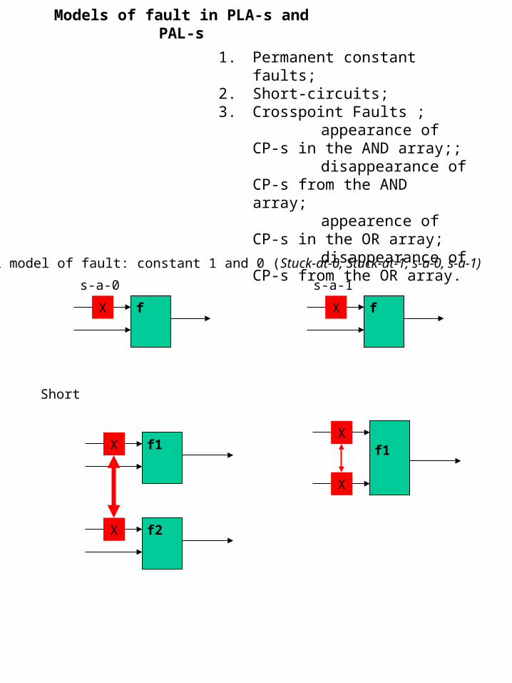
1. Permanent constant faults;2. Short-circuits;3. Crosspoint Faults ;
appearance of CP-s in the AND array;;
disappearance of CP-s from the AND array;
appearence of CP-s in the OR array;
disappearance of CP-s from the OR array.
Models of fault in PLA-s and PAL-s
fX fX
s-a-1s-a-0
f1X
f2X
Short
Classical model of fault: constant 1 and 0 (Stuck-at-0, Stuck-at-1, s-a-0, s-a-1)
f1X
X

1 1 1+V
x 1 x 2 x 3
0
y 1 y 2
y1 = x1 x2 x3 + x1 x2 x3 + x1 x2
y2 = x1 x2 x3 + x1 x2
s-a-1
X3 s-a-1faulty1 = x1 x2 + x1 x2 x3 + x1 x2
y2 = x1 x2 + x1 x2
Permanent constant faults in PLA/PAL-s

Crosspoint Faults Appearance of CP-s to in the AND array
1 1 1+V
x 1 x 2 x 3
0
y 1 y 2
y1 = x1 x2 x3 + x1 x2 x3 + x1 x2
y2 = x1 x2 x3 + x1 x2 Unnecessary CPy1 = x1 x2 x3 + x1 x2 x3 + x1 x2 x3
y2 = x1 x2 x3 + x1 x2 x3
UnnecessaryvariableShrinkage fault
Carnaugh Map
1 0
0
0
0
0
11
x10
1
00 01 11 10
x2x3y2
1 0
0
0
0
0
01x1
0
1
00 01 11 10
x2x3y2
Faultless Faulty

Disappearance of CP-s from the AND array
1 1 1+V
x 1 x 2 x 3
0
y 1 y 2
y1 = x1 x2 x3 + x1 x2 x3 + x1 x2
y2 = x1 x2 x3 + x1 x2 CP does not exist y1 = x1 x2 x3 + x1 x2 x3 + x1 x2
y2 = x1 x2 x3 + x1
Growth fault
Carnaugh Map
1 0
0
0
0
0
11
x10
1
00 01 11 10
x2x3y2
1 0
1
0
1
0
11x1
0
1
00 01 11 10
x2x3y2
Faultless Faulty
CP does not exist

Appearance of a new CP to the OR-array
1 1 1+V
x 1 x 2 x 3
0
y 1 y 2
y1 = x1 x2 x3 + x1 x2 x3 + x1 x2
y2 = x1 x2 x3 + x1 x2 Unnecessary CPy1 = x1 x2 x3 + x1 x2 x3 + x1 x2
y2 = x1 x2 x3 + x1 x2 + x1 x2 x3
Carnaugh Map
1 0
0
0
0
0
11
x10
1
00 01 11 10
x2x3y2
1 0
1
0
0
0
11x1
0
1
00 01 11 10
x2x3y2
Faultless Faulty
Appearance fault

1 1 1+V
x 1 x 2 x 3
0
y 1 y 2
y1 = x1 x2 x3 + x1 x2 x3 + x1 x2
y2 = x1 x2 x3 + x1 x2 CP does not exist y1 = x1 x2 x3 + x1 x2 x3 + x1 x2
y2 = x1 x2 x3
Carnaugh Map
1 0
0
0
0
0
11
x10
1
00 01 11 10
x2x3y2
1 0
0
0
0
0
00x1
0
1
00 01 11 10
x2x3y2
Faultless Faulty
Disappearance fault
Disapperance of the CP from the OR-array
CP does notexist

Missing CP-s are equivalent to some constant faults (Stuck-at-0/1) but additional CP-s do notcorrspond to that model.
n – number of inputsm – number of termsk – number of outputs
(2n + k) – different single and manifold CP faults
2 - 1 -different single and manifold CP faults(2n + k)m
CP faults may be untestifyiable in case of excessive functions
For example:
y1 = x1 + x2 + x1 x2 = x1 + x2
The missing of CP corresponding to whichever variable is not testifyiable in the AND array.
The missing of CP corresponding to this term is not testifyiable in theOR array.

1. Traditional methods for circuits equivalent to PAL/PLA-s;2. Random testing3. Exhaustive testing4. Semirandom methods 5. Deterministic Methods
Generation of tests for PLA-s and PAL-s
Traditional methods for equivalent circuits.
&
&
1
Cons:1.Ineffective due to convergent branching2. CP faults cannot be described as traditional s-a-0/1 faults.

Random testing
&0 0 1 1
0 1 1 0
0 0X
s-a-000
&0 0 1 1
0 1 1 0
0X
s-a-111 0
Discovery of the fault in AND array.
1
0
11
1
00/1 0/1 1
1 0
1/0 1/0
Bringing the impact of the fault to the outputthrough OR array
PAL/PLA...
ReactionsRandom combinations
Cons:1. A very large number of tests as in AND array combinations
where only one input is 1 and the rest are 0scan be used as tests.
2. A very large number of tests as the transport through the OR array requires that one input equals 1 and the rest are 0s.

Exhaustive testing and semirandom methods
PAL/PLA...
ReactionsAll possible combinations
Cons: A large number of tests when real arrays are considered (for example, 50 inputs, 67 outputs, 190 terms)
Exhaustive testing
Semirandom method
PAL/PLA...
ReactionsGenerator of
pseudorandom numbers
&0 1 1
1 0 1
1 1 0
Random numbers are not used. In stead, numbers with only one 0 are used.

Deterministic Test Generation
Special algorithms oriented at the structure of the array and testing of CP-s.
1 1 1+V
x 1 x 2 x 3
0
y 1 y 2
y1 = x1 x2 x3 + x1 x2 x3 + x1 x2
y2 = x1 x2 x3 + x1 x2
Example: let us test whether x1x2 has been Added in the function y2 with CP x3.
Let us define the operation: a # b = a b
Activating the impact of the fault: a = term that can be tested without faults b = term than can be tested with faults
Example. x1 x2 # x1 x2 x3 = x1 x2(x1 x2 x3) = x1 x2 x3
Transport of the impact of the fault to the output: a =result of the previous operation, b =functiwithout the tested term
Example. x1 x2 x3 # x1 x2 x3 = x1 x2 x3 (x1 x2 x3 ) = x1 x2 x3
Test : x1 = 1 x2 = 1
x3 = 0
1 1 0
1/0
0
1/0
0 0 1

Testable PLA Design
What is the objective?
Concurrent testing
Fault masking
Special Design
Self-testing
Test generation
YesNo
No
Yes
No
Yes
Yes No
Yes No
Must be taken into consideration:1. Indicators of testability;2. Impact on the original design;3. Requirements for the testing environment;4. Cost of design

Buffer
AND OR
. . .
.
.
.
. . .
x 1 x 2 x n
y1 y2 y m
Concurrent testing of PAL/PLA-s I
Examples of testable PLA/PAL-s
TSCTwo-rail Checker
f g
Ad
dit
ion
al li
ne TSC
1-out-of-mcode checker
Parity check
f g
faultless/faulty
Totaly Self Cheking (TSC) Two-rail Checker
x0 x1 y0 y1 x0 x1 y0 y1 f
TSCTwo-rail Checker
f g
g
0 1 0 1 0 1
1 0 1 0 0 1
1 0 0 1 1 0
0 1 1 0 1 0
If x0 = y0 and x1 = y1 then f = g
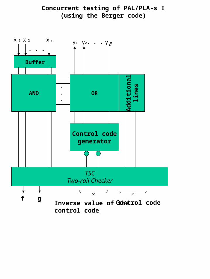
Concurrent testing of PAL/PLA-s I(using the Berger code)
Buffer
AND OR
. . .
.
.
.
. . .x 1 x 2 x n y1 y2 y m
Ad
dit
ion
alli
nes
TSCTwo-rail Checker
f g
Control codegenerator
Inverse value of thecontrol code
Control code

Berger code
0 1 1 0 1 0 1 1
Orders of infoOrder of control (number of 0s in the code)
011
Control ordergenerator
Orders of info
Orders of control
Comparison scheme True/false
Modifyied Berger code for a set of functions.
0 1
0
1
0
0
11x1 x2
00
00 01 11 10
x3x4y1
1 1
0
0
0
0
11
01
11
10
1 0
1
0
0
0
10x1 x2
00
00 01 11 10
x3x4y3
1 0
1
0
0
1
11
01
11
10
1 0
0
0
0
1
11x1 x2
00
00 01 11 10
x3x4y2
1 0
0
0
0
0
11
01
11
10
01 10
10
10
11
10
0001x1 x2
00
00 01 11 10
x3x4c1 c2
00
10
11
11
10
0000
01
11
10
10

PAL/PLA testable with universal tests
AND OR
. . .
.
.
.
. . .
x 1 x n
y1 y2 y k
c1
c2
s1
sm
. . .
sm+1
Par
ity
chec
k
z1
Additional line
Parity check
Additionalline
z2
Sel
ecti
on o
f te
rms
Decoder of the modified inputs
Decoder of the modifiedinputs
1
&
&
b2i-1
b2i
xi
c1 c2
It is possible to test an array without knowing how it has been programmed. The testing is not concurrent.

x1 … xi … xn c1 c2 s1 … sj … sm z1 z2 I1 - … - … - - - 0 … 0 … 0 0 0 For j=1, … , m
Ij0 0 … 000 … 0 1 0 0 … 010 … 0 1 1 Ij1 1 … 111 … 1 0 1 0 … 010 … 0 1 1 For I=1, … , n
Ji0 1 … 101 … 1 0 1 1 … 111 … 1 em - Ji1 0 … 010 … 0 1 0 1 … 111 … 1 em -
Universal tests
em =0, if m is odd1, if m is even
The length of the tests is 1+m+n, wherem is the number of terms and n is that of inputs.

A built-in Self-Testable PLA with Cumulative Parity Comparision
AND(the number of
used CP-s at each linemust be odd))
OR(the number of
used CP-smt each line must
be even)
. . .
.
.
.
. . .
x 1 x n
y1 y2 y k
c1
c2
s1
sm
. . .
sm+1
Additional line
Parity check
Ad
dit
ion
al li
ne
Sel
ecti
on o
f te
rms
Decoder of the modified inputsxor
T
Dz
While transmitting universal tests (n+m+1) the trigger takes at each test series the opposite value according to the previous series.

Methods using signature
LFSR - Linear Feedback Shift Register
T T + T T+
Signature Analyzer
T T + T T+++
Parallel.
Series
T T T T+
+
Signal from the checked object
Signals from the checked object

Buffer
AND OR
. . .
.
.
.
. . .
x 1 x 2 x n
y1 y2 y m
LFSR(Generator of
pseudorandomnumbers)
Signature analyzer I
Signature analyzer II
All possible input combinations may be usedinstead of the generator of pseudorandomnumbers

PLA/PAL with BILBO-s.
BILBO – Built-in Logic-Block Observer
LFSR that can be activated as the generator of pseudorandom numbers or as signature analyzer (depending on the conditions chosen)
Buffer
AND OR...
. . .y1 y2 y m
BILBO I BILBO II
BILBO III
. . .x 1 x 2 x n
More methods for improving the testability
1. Counting of CP-s. Presupposes the conductivity of bit lines and term lines. Presupposes that the expected CP numbers are known (functioning array)2. feedback from the signature analyzer to the inputs (to the LFSR generating pseudorandom values). Thus ate these blocks united into one. 3. several signature analyzers are used for testing both the AND and OR part. For example, one is used for testing even bit lines and the other for odd. It results in the better use of the chip area as the analyzer behind the bit lines requires more space than the bit lines. 4. AND and OR arrays are divided into parts that enables to test them simultaneously. Presupposes that additional requirements are set for thr programming of PAL/PLA-s.
Recommended


![µ ] v - Casa Montessori · µ ] v 7lwoxo , x x x x x x x x x x x x x x x x x x x x x x x x x x x x x x x x x x x x x x x x x x x x x x x x x x x x x x x x x x x x x x x x x x x x](https://img.pdfslide.net/doc/110x75/5e3041645d2be568cb68ec81/-v-casa-v-7lwoxo-x-x-x-x-x-x-x-x-x-x-x-x-x-x-x-x-x-x-x-x-x-x-x-x-x.jpg)