Nishant, Raminder, Harpreet; International Journal of Advance Research, Ideas and Innovations in Technology.
1
ISSN: 2454-132X
(Volume2, Issue2)
THE ANALYTICAL STUDY OF MESHING OF
DOUBLE HELICAL GEAR
Er. NISHANT SAINI Department of Mechanical Engineering,
Rayat Bahra University,
Er. RAMINDER SINGH Department of Mechanical Engineering,
Rayat Bahra University,
Er. HARPREET SINGH Department of Mechanical Engineering,
Rayat Bahra University,
ABSTRACT
Gears are the most important components of a Power Transmission System. The recent advancement and trend in
technology requires gears operating at high load capacities and speeds with reduced space requirement. A gear
normally fails when the tooth stress exceeds the allowable limit. So, it is essential to keep the maximum stress in a gear
tooth under a specified limit for a given loading conditions. Analysis of gears is carried out to find out the possible
laudation of failure and taking a corrective measure for the same. A gear failure is expensive not in terms of the cost of
replacement but due to the downtime and loss of production associated with the failure. Gear design should consider all
the possible loads that it can experience during its life. Surface fatigue and fracture is one of the major problem in gear
and gearbox design. In order to find out and analyze the exact location of failure and the stress value at which gear fails,
stress analysis of the double helical gear has been done in ANSYS. Load conditions to be experience by the gear has been
applied along with other constraints.
1. Introduction
1.1 New Method of Gear Design
The advancement in Computer technology has made Finite Element Analysis a routine tool in design. This has lead
Computer-Aided Design (CAD) using solid-body modelling. Some benefits of CAD are increased design productivity,
shorter design lead times, more logical design process & analysis, fewer design errors, greater accuracy in calculations,
standardization of design and improved procedures for reviews & revisions.
1.2 Finite Element Analysis (FEA)
It is widely used method of accessing a product performance. Using FEA, the requirement of prototype testing can be
greatly reduced thereby shortening the development cycle time. This further facilitates quicker product launch. FEA
consists of a computer model of the design on which a specified load is applied and analysed for the required results.
FEA gives an insight into the design like probable failure areas or areas with excessive margin for optimization, which
would otherwise will not be possible.
2. Literature Review
Nishant, Raminder, Harpreet; International Journal of Advance Research, Ideas and Innovations in Technology.
2
Ashish V Kadu and Sanjay S Deshmukh (2015)experimented that the transmission error in the actual gear system
which arises because of a irregular tool geometry or imperfect geometry or imperfect mounting the characteristic of the
involutes spur gear are analyzed by using finite element method. The contact stresses are examined by using 2D FEM
Model. And the bending stresses in the tooth root are examined by using 3D FEM Model. The conventional method of
calculating gear contact stress using Hertz’s theory for verification by 2D FEM analyser using ANSYS, the stiffness
relationship between two contact area is usually established using a spring place between source and target surfaces for
the contact generation between two gears. The stresses are compared with theoretical result. The static transmission error
and analysis of load sharing method using displacement vector and the effect of this error in the actual transmission
power of mesh gear.
Deva Ganesh et al. (2015)studied that the meshing between two gears contact stresses are evolved, which are
determined by using analyzing software called ANSYS. Finding stresses has become most popular in research on gears
to minimize the vibrations, bending stresses and also reducing the mass percentage in gears. These stresses are used to
find the optimum design in the gears which reduces the chances of failure. The model is generated by using Catia and
ANSYS is used for numerical analysis. The analytical study is based on Hertz,s equation. Study is conducted by varying
the geometrical profile of the teeth and to find the change in contact stresses between gears. It is therefore observed that
more contact stresses are obtained in modified gears. Both the results calculated using ANSYS and compared according
to the given moment of inertia.
Sarfraz Ali N. Quadri and Dhananjay R. Dolas (2015)experimented an attempt to summarize about stresses developed
in a mating spur gear which has involute teeth. A pair of spur gears are taken from a lathe gear box and progressed
onward to calculate stresses. Conventionally the analysis is carried out analytically using Lewis formulae and then Finite
Element Analysis is used for the same. Some stress relieving features have been incorporated in the teeth to know their
effect on the stress concentrations. A finite element model of teeth is considered for analysis and geometrical features of
various sizes are introduced at various locations and their effect is analyzed.
Mohammad Jebran Khan et al. (2015)experimented that the gears or toothed wheels form a positive drive for power
transmission system in precision machines wherein a definite velocity ratio is needed. Despite having high cost,
complicated manufacturing, need of precise alignment of shafts and lubrication, the gear drives are preferred over other
power transmission drives. One of the important reasons of preference being that of efficiency which is very high in gear
drives, even up to 99 percent in case of spur gears. Spur gears are the simplest of the gear drives having teeth cut parallel
to the axis of the shaft. The contact stress analysis of Stainless Steel spur gears by theoretical method using Hertz
equations and by Finite Element Analysis using FEA software ANSYS workbench .
Putti Srinivasa Rao et al. (2015)studied that the contact stress in the mating gears is the key parameter in gear design.
Deformation of the gear is also another key parameter which is to be considered. Gears generally fail when the working
stress exceeds the maximum stress. The complex design problem of spur gear which requires fine software skill for
modeling and also for analyzing. The project aims at the minimization of both contact stress as well as deformation to
arrive at the best possible combination of driver and driven gear. In this process of spur gears mating, 3 different
materials were selected and the software programme was performed for 9 different combinations to get the best result
possible. The results of the two dimensional FEM analysis from ANSYS are presented.
Sabah Khan(2015)studied that the gears are one of the most critical components in mechanical power transmission
systems. Transmission error is considered to be one of the main contributors to noise and vibration in a gearset.
Transmission error measurement has become popular as an area of research [14]. To estimate transmission error in a gear
system, the characteristics of in volute gears were analyzed using ANSYS. The contact stresses were examined using 2-D
FEM models. The bending stresses in the tooth root were examined using a 3-D FEM model.
3. Problem Definition
3.1 Definition of the Problem
Two stages of the Gear Box were analyzed for the given load conditions. The maximum stress generated under the load
needs to be evaluated. Further, geometry of the gear was modified to reduce the stress concentration values for the same
loading conditions.
3.2 Methodology Used
Nishant, Raminder, Harpreet; International Journal of Advance Research, Ideas and Innovations in Technology.
3
The Gear profile calculations of Double Helical gear were performed using reference from handbook data. The gear and
the assembly of the Gears was then generated in Solid Works [5]. The 3D model generated in Solid Works was then
transferred to Ansys Workbench. Material definition was given using Engineering Data. Mesh was generated using
Ansys Mesher. Boundary conditions were supplied and stress analysis was performed.
3.3 Constraints
The following inputs were used:
1. Material: - The gears were made of forged steel having specification EN24 as it is most economical.
2. Type of Gear: - Type of gear is double helical gear.
3. Helix Angle and Pressure Angle: - The helix angle and pressure angle are 15 and 20 respectively.
4. Pitch Circle Diameter: - The pitch circle diameters of the gears mounted in the gearbox were fixed.
5. Number of Gears: - The number of gears mounted in the gearbox was fixed.
6. Gear Module and PCD: -Dimensions of the double helical gear to be used are as given in the table below :
Diameter (mm)
Number of
teeth Module
Centre Distance
(mm)
Torque to be
Transmitted (Nm)
204 18 10
420.0 156,000
636 60 10
234 17 12
454.5 50,900
675 52 12
Table 1.1: Dimensions of the Double Helical Gear
Shaft diameter is 75mm. Gears of same module will mesh together to form a stage of reduction. Tooth width was taken
as 100mm and total width of the Gear was taken as 229mm. Input Power and rpm at Ist stage input is 800kW and 500
rpm respectively.All the above inputs were kept fixed and cannot be changed.
3.4 Basis of Modifications of the gearbox
Design modifications in the gears can be done considering factors such as strength and stiffness. But the gear module,
width, material and loading conditions cannot be changed [3].
3.5 Procedure for the Analysis
The following steps were used for solving of the problem:-
Step I: Modelling of the gears as per the dimensions and making assembly of two gears to make one reduction stage
using Solid Works.
Step II: The 3D model was imported in Ansys Workbench.
Step III: Material Property of EN24 was defined in Engineering Data in Ansys Workbench.
Step IV: The material EN24 was assigned to the Gears in Mechanical interface.
Step V: Frictional contact was specified between the faces of the gears mating each other.
Step VI: Frictional contact was specified between the faces of the gears mating each other.
Step VII: Mesh was generated for the gears using an element size of 4mm at the contact face.
Step VIII: The shaft bore of small gear was fixed and moment was applied at shaft bore of large gear. A moment of
50,900 Nm &156,000 Nm was applied at shaft bore of Gear Dia 636 &Dia 675 respectively.
Nishant, Raminder, Harpreet; International Journal of Advance Research, Ideas and Innovations in Technology.
4
Step IX: Analysis solution was performed and stress values were checked for the gears.
Step IX: Analysis solution was performed and stress values were checked for the gears. Von Misses stress was used to
compare the results.
Step X: The gear geometry was modified in Solid Works and all the steps from Step I to Step IX were performed again
to get the results for the revised geometry. The results of original gear and with modified geometry were compared.
3.6 Stress Analysis of the Gears
3D Model of the Gears used for Analysis
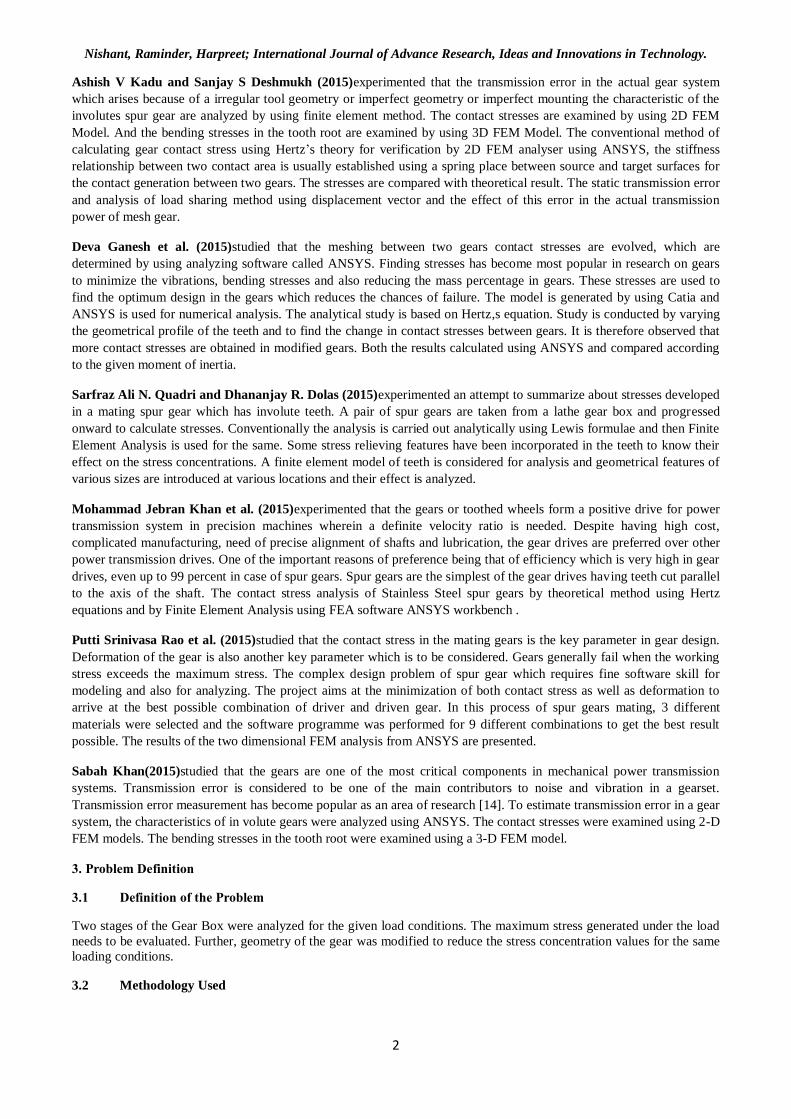
The 3D model and the drawing of the Gears and their assembly is in Fig. 3.1 to Fig. 3.4
Fig.3.1: 3D Model & 2D Drawing of Gear Assembly of Module 10 Gear Dia 204 &Dia 636
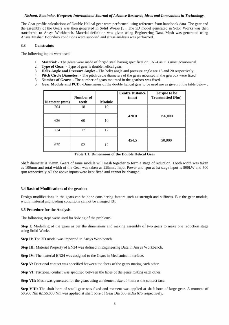
Fig. 3.2: Module 10 Gear Dia 204 &Dia 636
Fig. 3.3: Model & 2D Drawing of Gear Assembly of Module 12 Gear Dia 234 &Dia 675
Nishant, Raminder, Harpreet; International Journal of Advance Research, Ideas and Innovations in Technology.
5
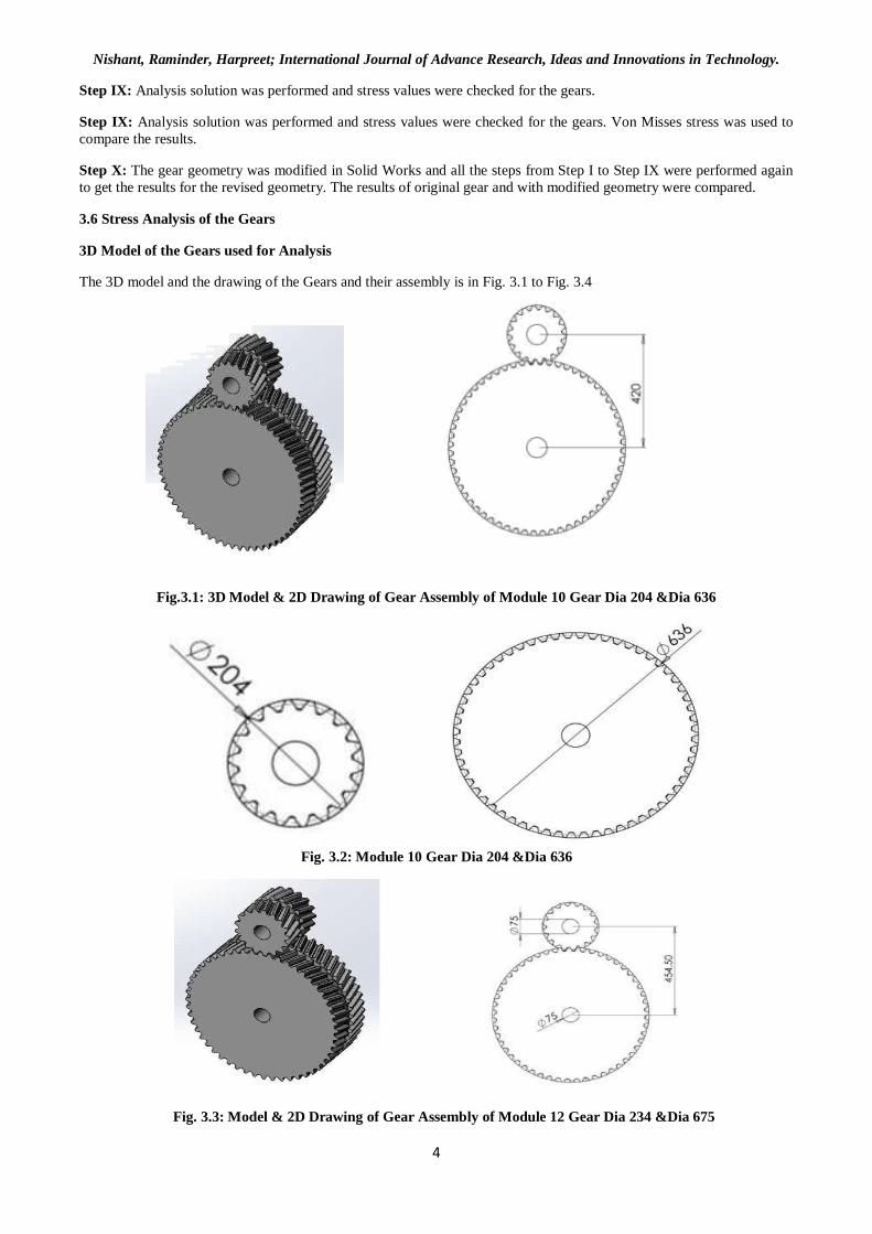
Fig. 3.4: Module 12 Gear Dia 234 &Dia 675
The following dimensions were maintained for the Gear Model:
Diameter (mm) Tip Diameter (mm)
Root Diameter
(mm)
Tooth Depth (mm)
204 218.8 183.8
17.5
636 635.6 618.6
234 249.6 212.0
18.8
675 693.8 656.3
Table 1.2: Dimensions of the Gear Model
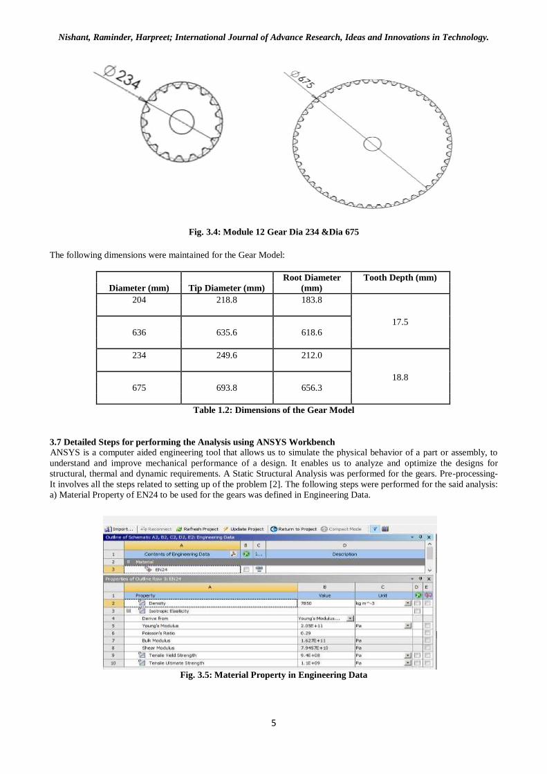
3.7 Detailed Steps for performing the Analysis using ANSYS Workbench ANSYS is a computer aided engineering tool that allows us to simulate the physical behavior of a part or assembly, to
understand and improve mechanical performance of a design. It enables us to analyze and optimize the designs for
structural, thermal and dynamic requirements. A Static Structural Analysis was performed for the gears. Pre-processing-
It involves all the steps related to setting up of the problem [2]. The following steps were performed for the said analysis:
a) Material Property of EN24 to be used for the gears was defined in Engineering Data.
Fig. 3.5: Material Property in Engineering Data
Nishant, Raminder, Harpreet; International Journal of Advance Research, Ideas and Innovations in Technology.
6
a. The gear assembly was imported in Design Modeller.
b. Material EN24 was assigned to the Gears in Mechanical interface.
c. Frictional contact was defined for the touching faces of the gears
d. Contact size element was specified as 4mm. And the mesh was generated giving the total no. of elements as
50767 for M12 Gears & 81289 for M10 Gears.
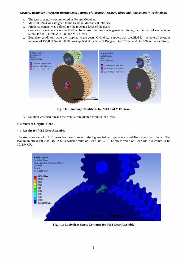
e. Boundary conditions were then applied to the gears. Cylindrical support was specified for the hole of gears. A
moment of 156,000 Nm & 50,900 was applied at the hole of Big gear Dia 675mm and Dia 636 mm respectively
Fig. 3.6: Boundary Conditions for M10 and M12 Gears
f. Solution was then run and the results were plotted for both the Gears.
4. Results of Original Gear
4.1 Results for M12 Gear Assembly
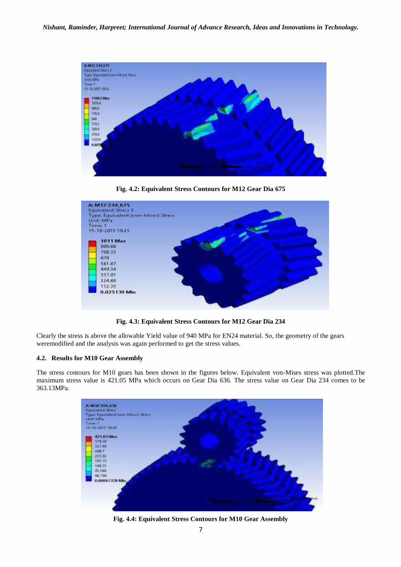
The stress contours for M12 gears has been shown in the figures below. Equivalent von-Mises stress was plotted. The
maximum stress value is 1168.2 MPa which occurs on Gear Dia 675. The stress value on Gear Dia 234 comes to be
1011.0 MPa.
Fig. 4.1: Equivalent Stress Contours for M12 Gear Assembly
Nishant, Raminder, Harpreet; International Journal of Advance Research, Ideas and Innovations in Technology.
7
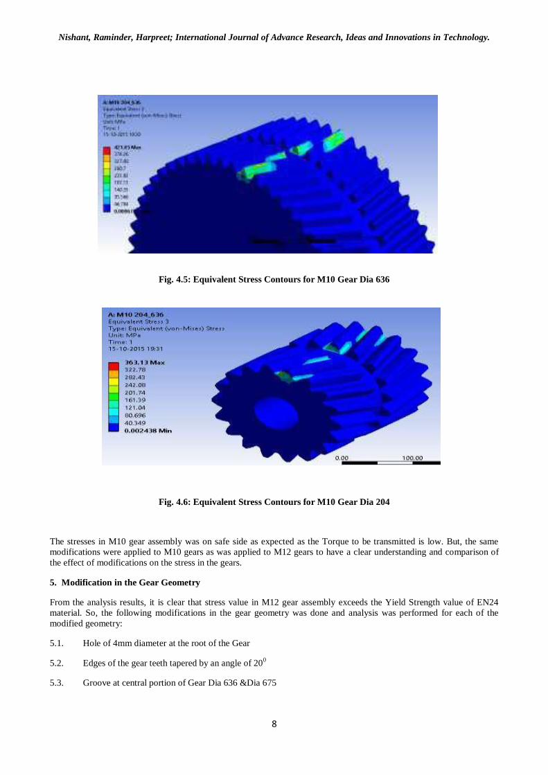
Fig. 4.2: Equivalent Stress Contours for M12 Gear Dia 675
Fig. 4.3: Equivalent Stress Contours for M12 Gear Dia 234
Clearly the stress is above the allowable Yield value of 940 MPa for EN24 material. So, the geometry of the gears
weremodified and the analysis was again performed to get the stress values.
4.2. Results for M10 Gear Assembly
The stress contours for M10 gears has been shown in the figures below. Equivalent von-Mises stress was plotted.The
maximum stress value is 421.05 MPa which occurs on Gear Dia 636. The stress value on Gear Dia 234 comes to be
363.13MPa.
Fig. 4.4: Equivalent Stress Contours for M10 Gear Assembly
Nishant, Raminder, Harpreet; International Journal of Advance Research, Ideas and Innovations in Technology.
8
Fig. 4.5: Equivalent Stress Contours for M10 Gear Dia 636
Fig. 4.6: Equivalent Stress Contours for M10 Gear Dia 204
The stresses in M10 gear assembly was on safe side as expected as the Torque to be transmitted is low. But, the same
modifications were applied to M10 gears as was applied to M12 gears to have a clear understanding and comparison of
the effect of modifications on the stress in the gears.
5. Modification in the Gear Geometry
From the analysis results, it is clear that stress value in M12 gear assembly exceeds the Yield Strength value of EN24
material. So, the following modifications in the gear geometry was done and analysis was performed for each of the
modified geometry:
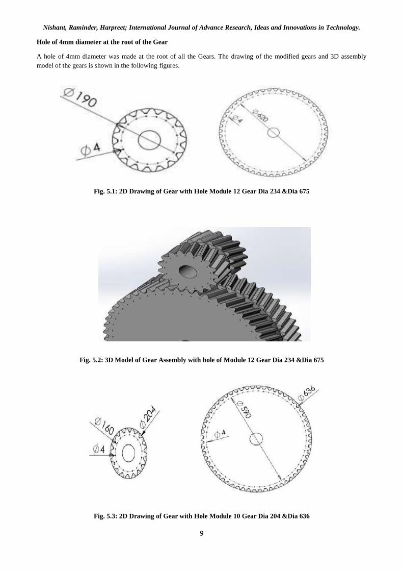
5.1. Hole of 4mm diameter at the root of the Gear
5.2. Edges of the gear teeth tapered by an angle of 200
5.3. Groove at central portion of Gear Dia 636 &Dia 675
Nishant, Raminder, Harpreet; International Journal of Advance Research, Ideas and Innovations in Technology.
9
Hole of 4mm diameter at the root of the Gear
A hole of 4mm diameter was made at the root of all the Gears. The drawing of the modified gears and 3D assembly
model of the gears is shown in the following figures.
Fig. 5.1: 2D Drawing of Gear with Hole Module 12 Gear Dia 234 &Dia 675
Fig. 5.2: 3D Model of Gear Assembly with hole of Module 12 Gear Dia 234 &Dia 675
Fig. 5.3: 2D Drawing of Gear with Hole Module 10 Gear Dia 204 &Dia 636
Nishant, Raminder, Harpreet; International Journal of Advance Research, Ideas and Innovations in Technology.
10
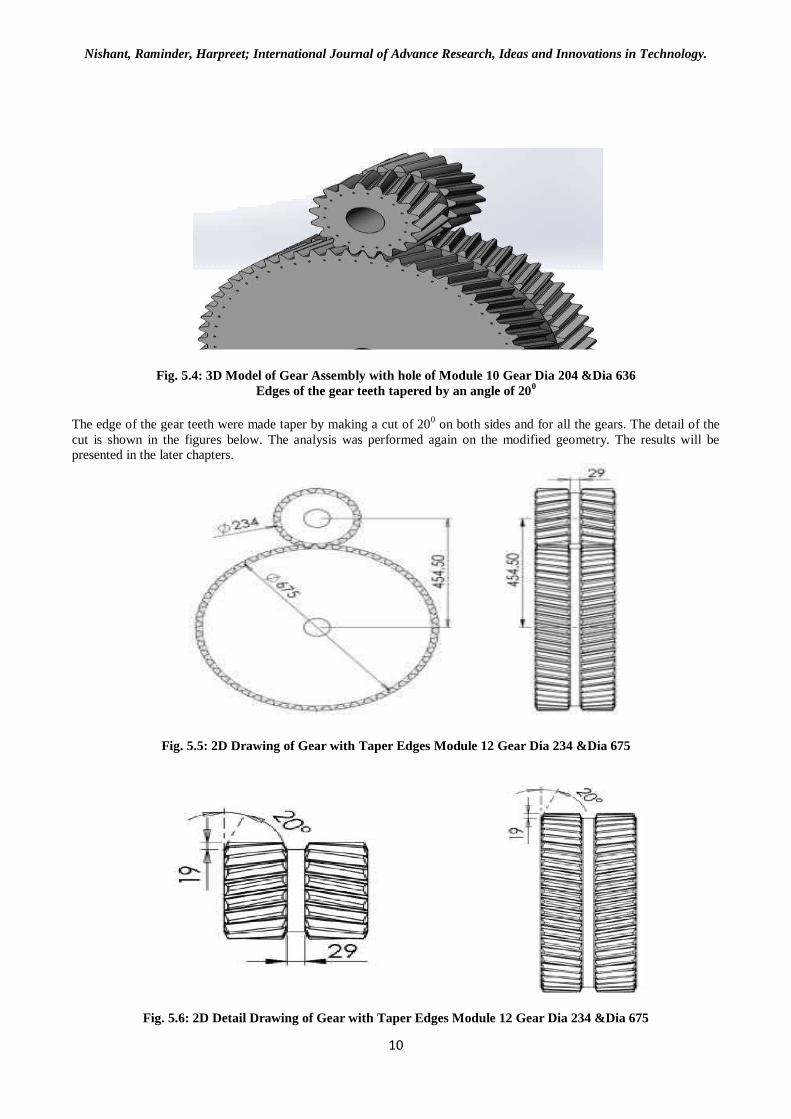
Fig. 5.4: 3D Model of Gear Assembly with hole of Module 10 Gear Dia 204 &Dia 636
Edges of the gear teeth tapered by an angle of 200
The edge of the gear teeth were made taper by making a cut of 20
0 on both sides and for all the gears. The detail of the
cut is shown in the figures below. The analysis was performed again on the modified geometry. The results will be
presented in the later chapters.
Fig. 5.5: 2D Drawing of Gear with Taper Edges Module 12 Gear Dia 234 &Dia 675
Fig. 5.6: 2D Detail Drawing of Gear with Taper Edges Module 12 Gear Dia 234 &Dia 675
Nishant, Raminder, Harpreet; International Journal of Advance Research, Ideas and Innovations in Technology.
11
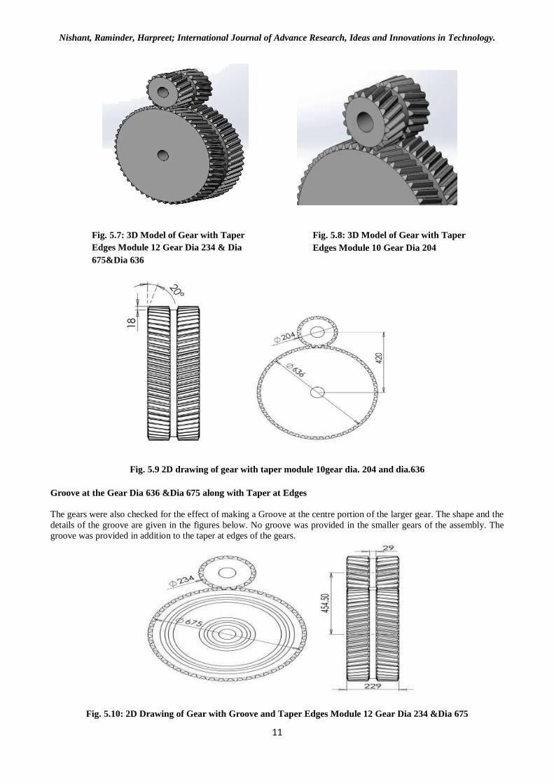
Fig. 5.9 2D drawing of gear with taper module 10gear dia. 204 and dia.636
Groove at the Gear Dia 636 &Dia 675 along with Taper at Edges
The gears were also checked for the effect of making a Groove at the centre portion of the larger gear. The shape and the
details of the groove are given in the figures below. No groove was provided in the smaller gears of the assembly. The
groove was provided in addition to the taper at edges of the gears.
Fig. 5.10: 2D Drawing of Gear with Groove and Taper Edges Module 12 Gear Dia 234 &Dia 675
Fig. 5.7: 3D Model of Gear with Taper
Edges Module 12 Gear Dia 234 & Dia
675&Dia 636
Fig. 5.8: 3D Model of Gear with Taper
Edges Module 10 Gear Dia 204
Nishant, Raminder, Harpreet; International Journal of Advance Research, Ideas and Innovations in Technology.
12
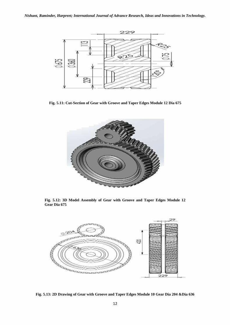
Fig. 5.11: Cut-Section of Gear with Groove and Taper Edges Module 12 Dia 675
Fig. 5.12: 3D Model Assembly of Gear with Groove and Taper Edges Module 12
Gear Dia 675
Fig. 5.13: 2D Drawing of Gear with Groove and Taper Edges Module 10 Gear Dia 204 &Dia 636
Nishant, Raminder, Harpreet; International Journal of Advance Research, Ideas and Innovations in Technology.
13
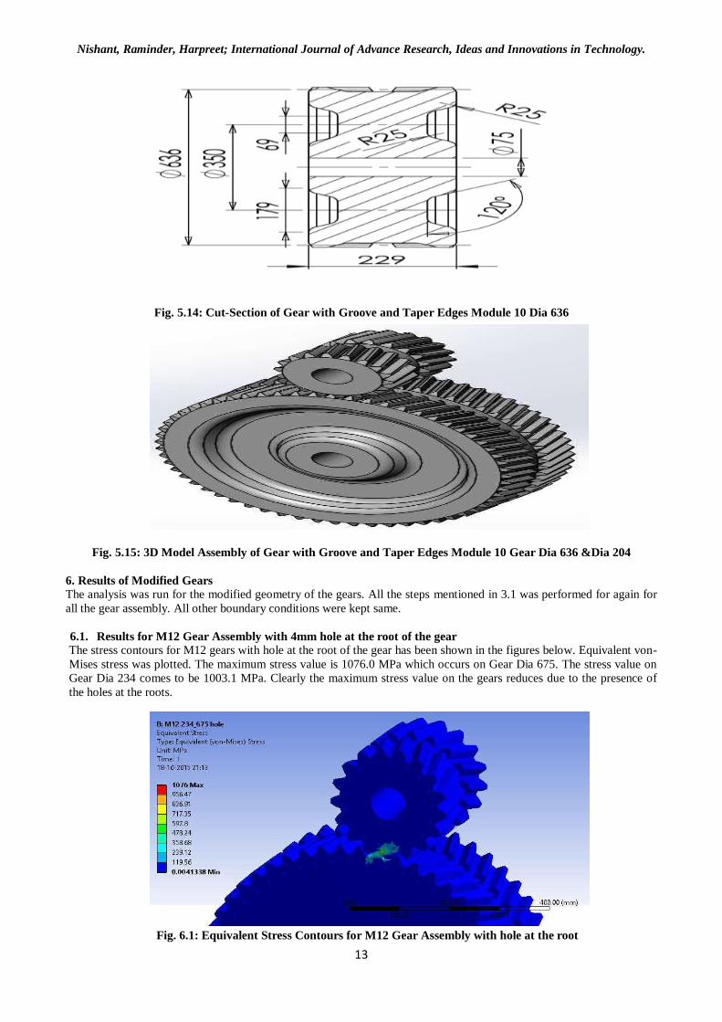
Fig. 5.14: Cut-Section of Gear with Groove and Taper Edges Module 10 Dia 636
Fig. 5.15: 3D Model Assembly of Gear with Groove and Taper Edges Module 10 Gear Dia 636 &Dia 204
6. Results of Modified Gears The analysis was run for the modified geometry of the gears. All the steps mentioned in 3.1 was performed for again for
all the gear assembly. All other boundary conditions were kept same.
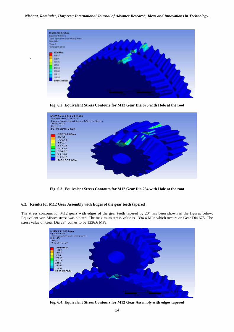
6.1. Results for M12 Gear Assembly with 4mm hole at the root of the gear
The stress contours for M12 gears with hole at the root of the gear has been shown in the figures below. Equivalent von-
Mises stress was plotted. The maximum stress value is 1076.0 MPa which occurs on Gear Dia 675. The stress value on
Gear Dia 234 comes to be 1003.1 MPa. Clearly the maximum stress value on the gears reduces due to the presence of
the holes at the roots.
Fig. 6.1: Equivalent Stress Contours for M12 Gear Assembly with hole at the root
Nishant, Raminder, Harpreet; International Journal of Advance Research, Ideas and Innovations in Technology.
14
.
Fig. 6.2: Equivalent Stress Contours for M12 Gear Dia 675 with Hole at the root
Fig. 6.3: Equivalent Stress Contours for M12 Gear Dia 234 with Hole at the root
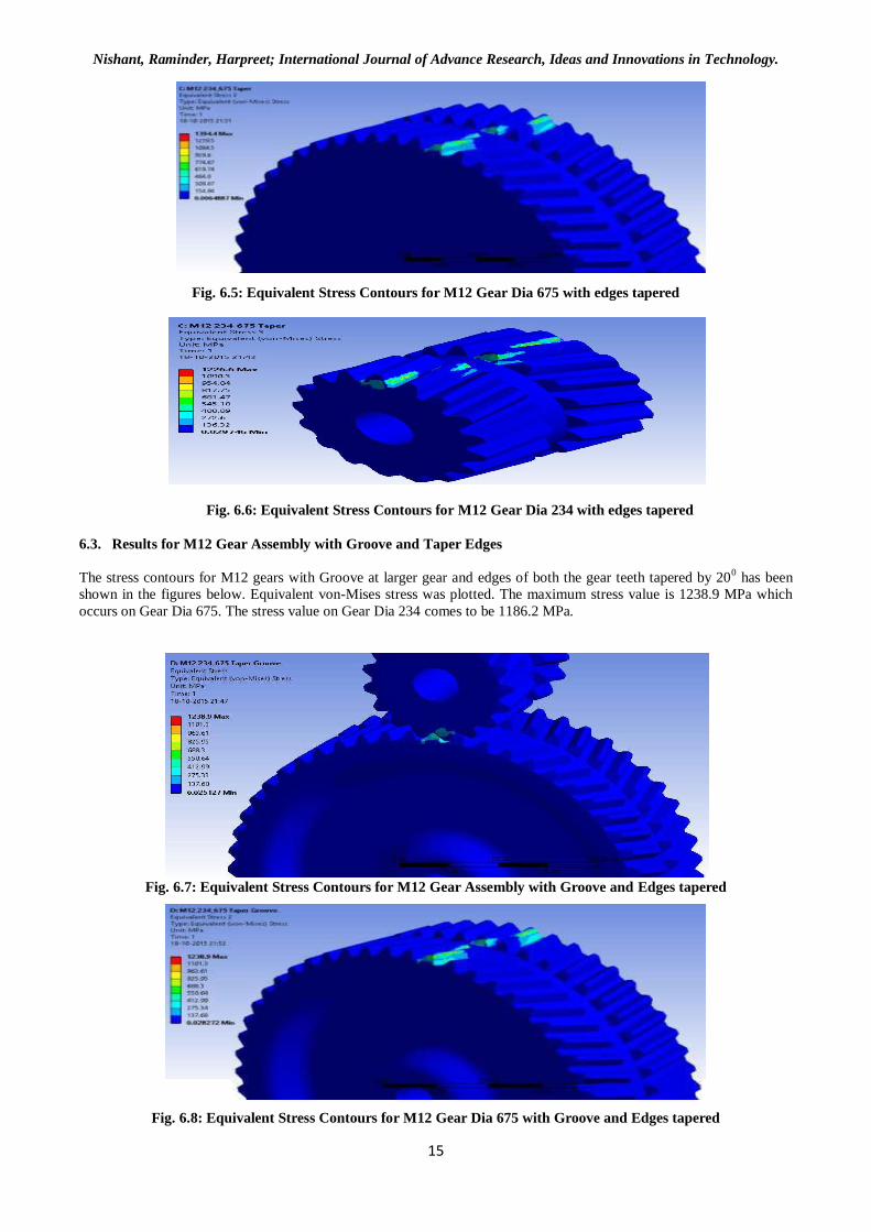
6.2. Results for M12 Gear Assembly with Edges of the gear teeth tapered
The stress contours for M12 gears with edges of the gear teeth tapered by 200 has been shown in the figures below.
Equivalent von-Misses stress was plotted. The maximum stress value is 1394.4 MPa which occurs on Gear Dia 675. The
stress value on Gear Dia 234 comes to be 1226.6 MPa
Fig. 6.4: Equivalent Stress Contours for M12 Gear Assembly with edges tapered
Nishant, Raminder, Harpreet; International Journal of Advance Research, Ideas and Innovations in Technology.
15
Fig. 6.5: Equivalent Stress Contours for M12 Gear Dia 675 with edges tapered
Fig. 6.6: Equivalent Stress Contours for M12 Gear Dia 234 with edges tapered
6.3. Results for M12 Gear Assembly with Groove and Taper Edges
The stress contours for M12 gears with Groove at larger gear and edges of both the gear teeth tapered by 200 has been
shown in the figures below. Equivalent von-Mises stress was plotted. The maximum stress value is 1238.9 MPa which
occurs on Gear Dia 675. The stress value on Gear Dia 234 comes to be 1186.2 MPa.
Fig. 6.7: Equivalent Stress Contours for M12 Gear Assembly with Groove and Edges tapered
Fig. 6.8: Equivalent Stress Contours for M12 Gear Dia 675 with Groove and Edges tapered
Nishant, Raminder, Harpreet; International Journal of Advance Research, Ideas and Innovations in Technology.
16
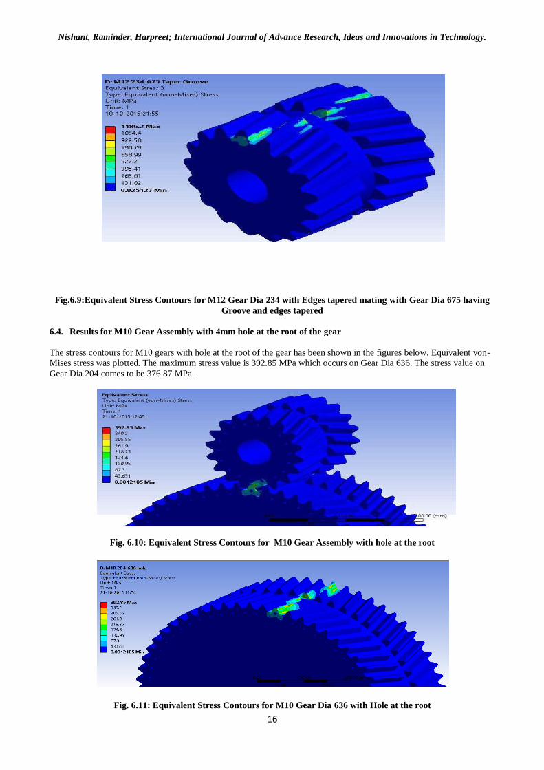
Fig.6.9:Equivalent Stress Contours for M12 Gear Dia 234 with Edges tapered mating with Gear Dia 675 having
Groove and edges tapered
6.4. Results for M10 Gear Assembly with 4mm hole at the root of the gear
The stress contours for M10 gears with hole at the root of the gear has been shown in the figures below. Equivalent von-
Mises stress was plotted. The maximum stress value is 392.85 MPa which occurs on Gear Dia 636. The stress value on
Gear Dia 204 comes to be 376.87 MPa.
Fig. 6.10: Equivalent Stress Contours for M10 Gear Assembly with hole at the root
Fig. 6.11: Equivalent Stress Contours for M10 Gear Dia 636 with Hole at the root
Nishant, Raminder, Harpreet; International Journal of Advance Research, Ideas and Innovations in Technology.
17
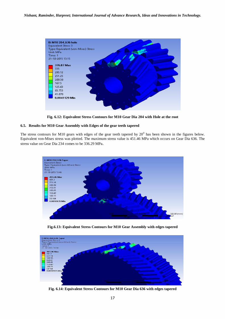
Fig. 6.12: Equivalent Stress Contours for M10 Gear Dia 204 with Hole at the root
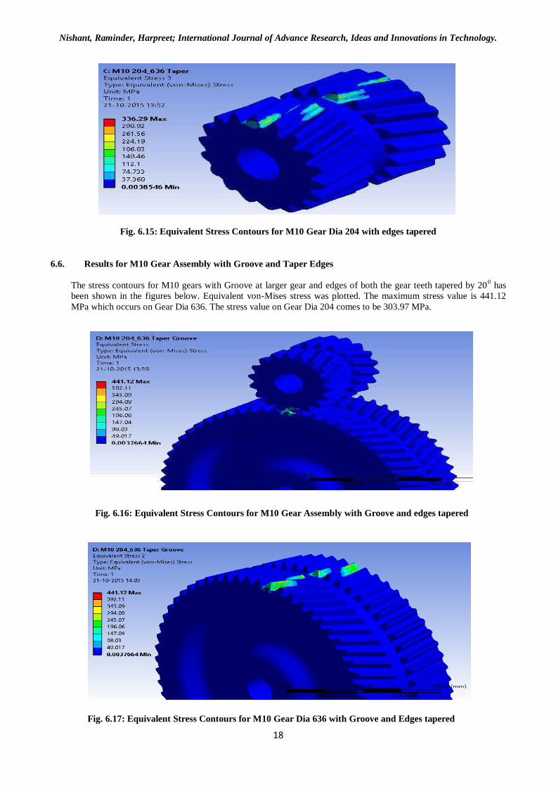
6.5. Results for M10 Gear Assembly with Edges of the gear teeth tapered
The stress contours for M10 gears with edges of the gear teeth tapered by 200 has been shown in the figures below.
Equivalent von-Mises stress was plotted. The maximum stress value is 451.46 MPa which occurs on Gear Dia 636. The
stress value on Gear Dia 234 comes to be 336.29 MPa.
Fig.6.13: Equivalent Stress Contours for M10 Gear Assembly with edges tapered
Fig. 6.14: Equivalent Stress Contours for M10 Gear Dia 636 with edges tapered
Nishant, Raminder, Harpreet; International Journal of Advance Research, Ideas and Innovations in Technology.
18
Fig. 6.15: Equivalent Stress Contours for M10 Gear Dia 204 with edges tapered
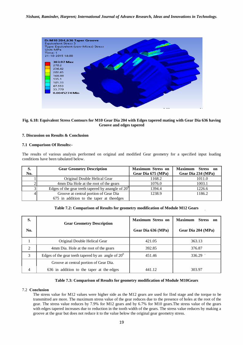
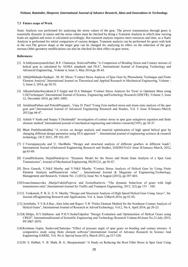
6.6. Results for M10 Gear Assembly with Groove and Taper Edges
The stress contours for M10 gears with Groove at larger gear and edges of both the gear teeth tapered by 200 has
been shown in the figures below. Equivalent von-Mises stress was plotted. The maximum stress value is 441.12
MPa which occurs on Gear Dia 636. The stress value on Gear Dia 204 comes to be 303.97 MPa.
Fig. 6.16: Equivalent Stress Contours for M10 Gear Assembly with Groove and edges tapered
Fig. 6.17: Equivalent Stress Contours for M10 Gear Dia 636 with Groove and Edges tapered
Nishant, Raminder, Harpreet; International Journal of Advance Research, Ideas and Innovations in Technology.
19
Fig. 6.18: Equivalent Stress Contours for M10 Gear Dia 204 with Edges tapered mating with Gear Dia 636 having
Groove and edges tapered
7. Discussion on Results & Conclusion
7.1 Comparison Of Results:-
The results of various analysis performed on original and modified Gear geometry for a specified input loading
conditions have been tabulated below.
S. Gear Geometry Description Maximum Stress on Maximum Stress on
No. Gear Dia 675 (MPa) Gear Dia 234 (MPa)
1 Original Double Helical Gear 1168.2 1011.0
2 4mm Dia Hole at the root of the gears 1076.0 1003.1
3 Edges of the gear teeth tapered by anangle of 200 1394.4 1226.6
4 Groove at central portion of Gear Dia 1238.9 1186.2
675 in addition to the taper at theedges
Table 7.2: Comparison of Results for geometry modification of Module M12 Gears
S. Gear Geometry Description
Maximum Stress on Maximum Stress on
No. Gear Dia 636 (MPa) Gear Dia 204 (MPa)
1 Original Double Helical Gear 421.05 363.13
2 4mm Dia. Hole at the root of the gears 392.85 376.87
3 Edges of the gear teeth tapered by an angle of 200 451.46 336.29
Groove at central portion of Gear Dia.
4 636 in addition to the taper at the edges 441.12 303.97
Table 7.3: Comparison of Results for geometry modification of Module M10Gears
7.2 Conclusion The stress value for M12 values were higher side as the M12 gears are used for IInd stage and the torque to be
transmitted are more. The maximum stress value of the gear reduces due to the presence of holes at the root of the
gear. The stress value reduces by 7.9% for M12 gears and by 6.7% for M10 gears.The stress value of the gears
with edges tapered increases due to reduction in the tooth width of the gears. The stress value reduces by making a
groove at the gear but does not reduce it to the value below the original gear geometry stress.
Nishant, Raminder, Harpreet; International Journal of Advance Research, Ideas and Innovations in Technology.
20
7.3 Future scope of Work
Static Analysis was performed for analyzing the stress values of the gear. The power transmission through gears is
essentially dynamic in nature and the stress values must be checked by doing a Transient Analysis in which time varying
loads are applied and stress is calculated accordingly. But transient analysis requires more resources and time, so a Static
Analysis is performed for initial comparison of various designs. Transient analysis can be performed for gears with hole
at the root.The groove shape at the larger gear can be changed for analyzing its effect on the reduction of the gear
stresses.Other geometry modifications can also be checked for their effect on gear stress.
References:
[1] A.SathyanarayanaAchari, R.P. Chaitanya, SrinivasPrabhu “A Comparison of Bending Stress and Contact stresses of
helical gear as calculated by AGMA standards and FEA”, International Journal of Emerging Technology and
Advanced Engineering , Volume 4, Issue 5, May 2014,pp 38-43.
[2] AbhijitMahadevSankpal , M. M. Mirza “Contact Stress Analysis of Spur Gear by Photoelastic Technique and Finite
Element Analysis”,International Journal on Theoretical and Applied Research in Mechanical Engineering, Volume -
3, Issue-2, 2014, pp 50-55.
[3] AlkunteSuhasSuryakant,S.Y.Gajjal and D.A Mahajan “Contact Stress Analysis for 'Gear' to Optimize Mass using
CAETechniques”,International Journal of Science, Engineering andTechnology Research (IJSETR), Volume 3, Issue
12, December 2014, pp 3491-3495.
[4] AniskhanPathan and PriteshPrajapati , Vijay D. Patel “Using Fem method stress and strain state analysis of the spur
gear pair”,International Journal of Advanced Engineering Research and Studies, Vol. I/ Issue II/January-March,
2012/pp 44-47.
[5] Ashish V Kadu and Sanjay S Deshmukh“ investigation of contact stress in spur gear usinglewis equation and finite
element method”,International journal of mechanical engineering and robotics research(2105), pp 28-37.
[6] Bhatt ParthJitendrabhai “A review on design analysis and material optimization of high speed helical gear by
changing different design parameter using FEA approach ” , International journal of engineering sciences & research
technology, OCT 2015 , PP 102-107.
[7] C.Veeranjaneyulu and U. HariBabu “Design and structural analysis of different gearbox in different loads”,
International Journal ofAdvanced Engineering Research and Studies, IJAERS/Vol.I/ Issue II/January-March, 2012,
pp.65-69.
[8] CemalDolicanin, DejanDimitrijevic “Dynamic Model for the Stress and Strain State Analysis of a Spur Gear
Transmission”, Journal of Mechanical Engineering 58(2012)1, pp 56-67.
[9] Deva Ganesh, V.Nikil Murthy and V.Nikil Murthy “Contact Stress Analysis of Helical Gear by Using Finite
Element Analysis andNumericial value” , International Journal & Magazine of Engineering,Technology,
Management and Research, Volume No: 2 (2015), Issue No: 8 August (2015), pp 597-603.
[10] IvanaAtanasovska ,MarijaVukšićPopovic and ZoricaStarčevic “The dynamic behavIour of gears with high
transmission ratio”,International Journal for Traffic and Transport Engineering, 2012, 2(2).pp 153 – 160.
[11] J. Venkatesh, P. B. G. S. N. Murthy “Design and Structural Analysis of High Speed Helical Gear Using Ansys”, Int.
Journal ofEngineering Research and Applications, Vol. 4, Issue 3,March 2014, pp 01-05.
[12] JerinSabu, Y.V.K.S.Rao ,Alen John and Rajeev V.R “Finite Element Method for the Nonlinear Contact Analysis of
Helical Gears”, International Journal of Research in AdventTechnology, Vol.2, No.4, April 2014, pp 20-23.
[13] K.Shilpa, D.V.Subbarao and P.H.V.SeshaTalpaSai “Design Evaluation and Optimization of Helical Gears using
CREO”, InternationalJournal of Scientific Engineering and Technology Research Volume.04,Issue No.21,July-2015,
PP:3967-3970.
[14] Krishanu Gupta, SushovanChatterjee “Effect of pressure angle of spur gears on bending and contact stresses: A
comparative study using finite element software”,International Journal of Advance Research In Science And
Engineering IJARSE, Vol. No.4, Special Issue (01), March 2015, pp.517-526.
[15] M. S. Hebbal, V. B. Math, B. G. Sheeparamatti “A Study on Reducing the Root Fillet Stress in Spur Gear Using

Nishant, Raminder, Harpreet; International Journal of Advance Research, Ideas and Innovations in Technology.
21
Internal StressRelieving Feature of Different Shapes” , International Journal of Recent Trends in Engineering, Vol.
1, No. 5, May 2009, pp 163-165.
[16] Manoj Singh, GurukulKangriVishwavidyalaya and Haridwar “The stress analysis of mating teeth of spur gear to
findmaximum contact stress in the gear teeth”, International Journal of Mechanical Engineering (IIJME), Volume 3,
Issue 3, March 2015, pp 18-21.Mohammad Jebran Khan ArunishManglaSajadHussain Din “Contact Stress Analysis
of Stainless Steel Spur Gears using Finite Element Analysis and Comparison with Theoretical Results using Hertz
TheorY” , Int. Journal of Engineering Research and Applications , Vol. 5,Issue 4 , April 2015, pp 10 -18.
[17]NagarajuGummadi and Rama Thirumurugan “Contact Stress Analysis of Normal Contact Ratio Gears considering
Load SharingEffect”, International Conference On Emerging Trends in Science Technology Engineering and
Management , 09th & 10th, October 2015 , pp 573-577.
[18]Yi-Cheng Chen, Chung-BiauTsay“ Stress analysis of a helical gear set with localized bearing contact”, ELSEVIER,
2002, pp 707–723.
Recommended