•
^
Technical Report
THE EFFECT OF BAROMETRIC PRESSURE VARIATION
ON THE "U.S.O!* LONG-PERIOD SEISMOMETER
by
PT. Eduard Berg and Ronald Rasir.ussen
Contract numbers F-44620-68-C-0066 and F-44620-70-C-0031
February 1970
Reproduced by the CLEARINGHOUSE
(or Federal Scientific & Technical Information Springfield Va. 22151
. . , , •.,.• -,-.r.va for public 3.0 This a0CAtnr:ry- ^ . ^ .. ^L i on ig unlimited
lS,©le
■1„'.,';,"'v'■•■■■■■"•",:'>",-"l'-':'-"-'-" ■:' " -'"" —' '" -'■ ■■■ .,■■ .^..■.■-■• •-■i-:-;;-':i;i^n^''i"

DISCLAIMER NOTICE
THIS DOCUMENT IS THE BEST
QUALITY AVAILABLE.
COPY FURNISHED CONTAINED
A SIGNIFICANT NUMBER OF
PAGES WHICH DO NOT
REPRODUCE LEGIBLY.
of ih§
UJtlVfXSlTY OP ALASKA
AFOSR Concract No.: Project Till«:
ARPA Order No.t ARPA Program Code No. Project Scientist:
Telephone Number:
F44620-68-C-0066 Tectonic Movetaenc, Defornation Release and Crustal Structure Studies in Alaska 292 9F10 Dr. Eduard Berg Geophysical Institute University of Alaska 907: 479-7373
AFOSR Contract No.: Project Title:
ARPA Order No. ARPA Program Code No.: Project Scientist:
Telephone Number:
F4A620-70-C-0031 Crustal Deformation, Release, Failure and Tilts in Alaska 292 0F10 Dr. Eduard Berg Geophysical Institute University of Alaska 907: 479-7373
i
! ?
Hi
THE eFrtiCT er BMumeriue
PW»SüRlf. VARIATI«« m THE "11.S.O."
by
Eduard Borg and Ronald Rasnusscn
ABSTRACT
The particular manner of mechanical construction of the Long-Period
U.S.O. package is responsible for the pressure sensitivity of the LP-X
component. The effect seems to be linear with pressure for periods larger
than the seismometer period and short compared to the feedback signal time
constant. Under the particular setting of the Gilmore (GLM) installation,
a pressure Induced displacement of the x component is Ax = -IS.Smyi Ap v bar
(without feedback).
Since the pressure Induced displacements are considered as very un-
k desirable noise for the instrument as either long period seismometer or I
as tiltmeter the borehole was pressure sealed and ehe effect removed. t
Records are presented to demonstrate the effect.
IHTROOUCnON
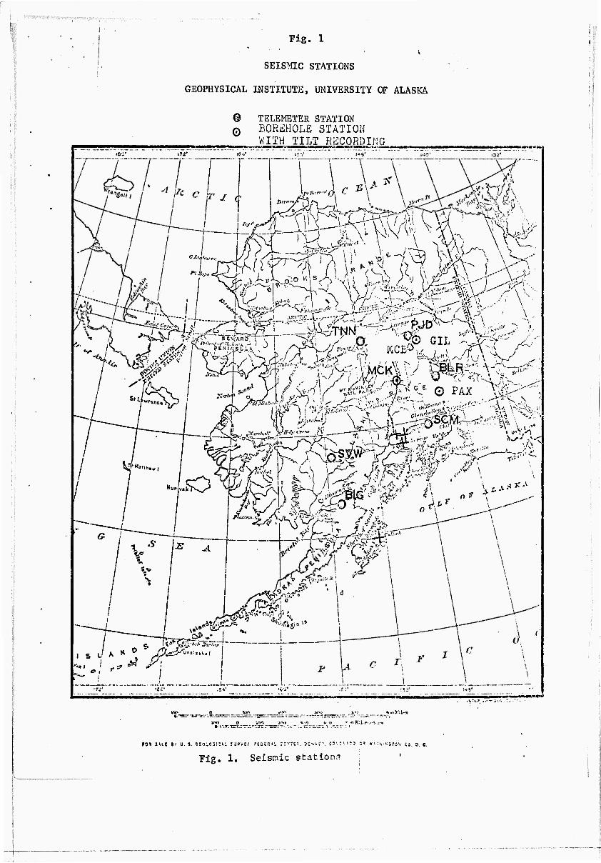
Three "UniBiinned Seismic Observatories" called briefly "U.S.01* have
been obtained and Installed In Central Alaska at the following sites:
MCK 63•44.02' N 148•55.95' W 610M (ground surface)
PAX 62058.19, N 145028.12' W 1034m '(ground surface)
GIM 64059.24l N 147023.34' W 722m (prelim) (ground surface)
They form a tripartite network In Central Alaska and are Included in the
large aperture telemeter system (see Fig. 1 for location). Each observ-
atory package contains 3-component short and long period seismometers.
The short-period instruments are of the "Ranger" type (To=l sec), the
long-period instruments are of the Lamont-Lunar-Ocean Bottom type
(To=15 sec) with feedback and remote-automatic leveling. They have been
described in a special report (Sandia Corporation, 1968).
INSTALLATION OF INSTRUMENTS
The sites have been selected to form a tripartite tilt network and be
useful for short and extreme long-period data recording and finally to
permit telemetry back to the seismic laboratory. The instruments have
been installed in boreholes with the help of the Sandia Corporation group
that had put them together and tested. The bottoms of the holes are at
the following depth below surrounding surface: GLM 15ft., PAX 38ft.,
MCK 28ft. GLM was installed in the late fall 1968 and operated in June
1969. PAX and MCK were installed in the summer of 1969 and operated some
time thereafter.
•
moawato» TO ORIGINAL BQuitfütOT
Since only ilu* horUitntal K component of tlie long-pertod tot (LP*X)
is of major Internst In connection wich the baronocrlc pressure variation,
only changes In Che long-period electronics are descrlbod. It might bo
mentioned that all these changes have been carried out by the Sandla group.
The transducer is a conventional capacltlvc type, with a carrier frequency
of 3000 Hz. After amplification, the modulated carrier is demodulated.
All the electronics involved to this point (excluding power supplies) is
physically located with the instrument package inside the borehole. The
demodulator output is fed through the feedback filter and a gain I
amplifier. The output of this amplifier returns to the seismometer feed-
back coil (with«30 db) restoring the beam towards its center position.
This output is also available for measurement (FB-X, Y or Z). The X and
Y components can be used to measure tilts, the Z component to measure
changes in gravity. The demodulator output (DEM-X, Y or Z) also goes to
a filter and post-amplifier circuit.
The filter on each LP instrument (in the Sandla configuration) is
peaking at 18 sec. which necessitates a feedback filter time constant of
1400 sec (10 Mf2 and 22 y F). This system has been changed as follows:
1) The filter and post amplifier circuit has been replaced by the
"Pomeroy Amplifier" which amplifier has a flat period response
i
from 20 to 200 sec. (in the "Broad" position) with a gain of
115. ■' -
2) To accommodate this much broader filter response the feedback
i filter time constant was lengthened from the original 1400 sec
S to 6000 sec. (R = 10 M n, C = (22 + 90) MF).

The senfiitivlty of the LP inscruKients varies trm lnstrue«nl t**
inntru&eiU. Since caleylacions tn the follwing chapter are baaed on
the "Fairbanks** LP-X» (Sandla designation) the channel sensitivity aa-
sumed Is 0.76 *b.57t Volis/nlcron at the Sandta hlgli gain output, or
roughly 25 nV/micron nt the demodulator output, before the feedback loop
(•30db,titnc constnnc 6000 sec) becomes effective (for the sensitivity,
see Sandla 1968, Table VII. p. 26).
SENSITIVITY OF THE LP-X COMPONENT TO ATMOSPHERIC PRESSURE VARIATIONS
The feedback outputs were connected at the stations to the FM
telemeter modules (range + 2.5 Volts) I RIG channels 1 through 7 were used.
The signals were transmitted either by radio links or later by phone
lines plus radio links and discriminated at the Geophysical Institute's
terminal in a 1 to 1 manner (a +1 Volt input signal producing a ■+1 Volt
output signal).
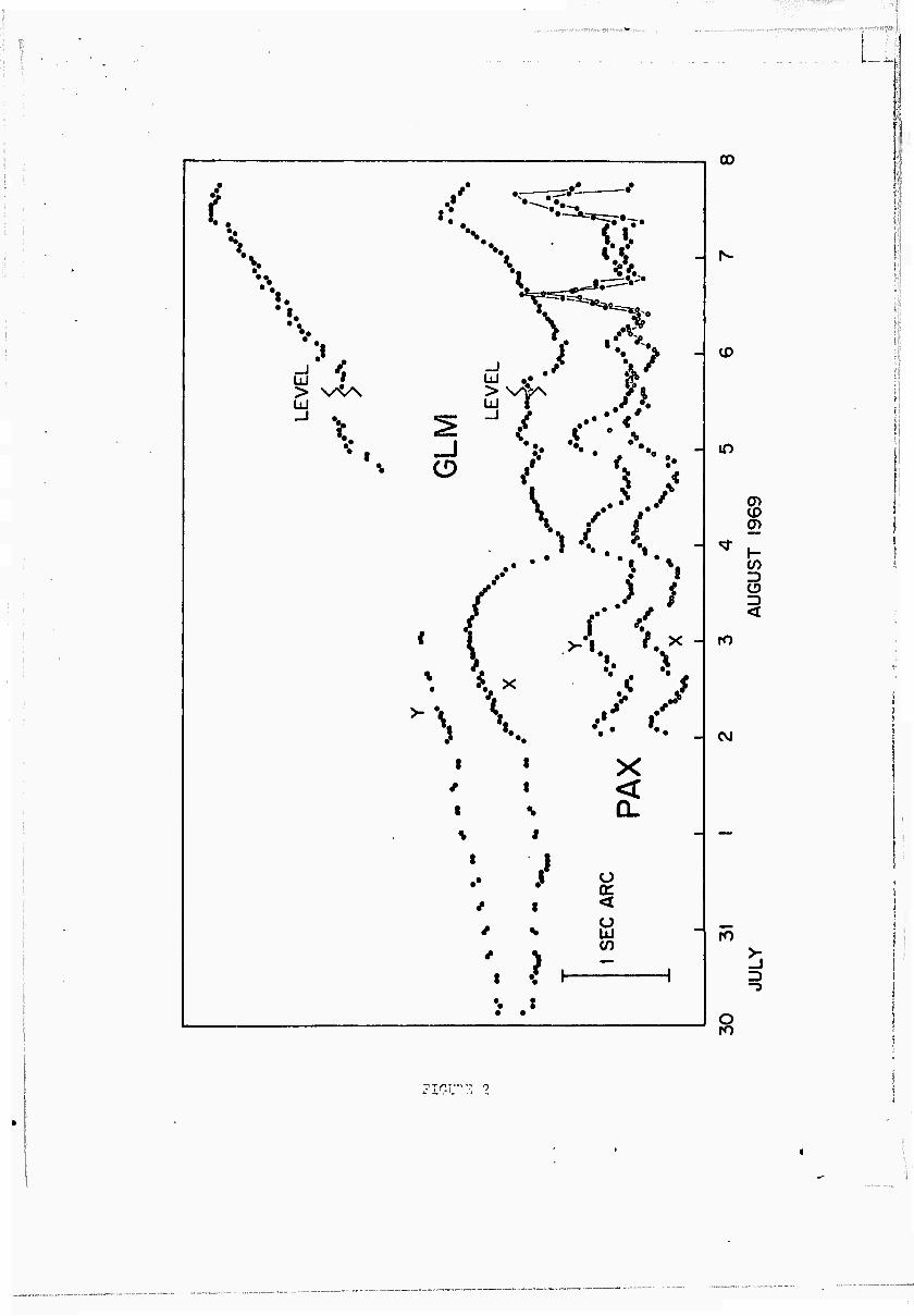
It was first found that the telemeter link, including the recording
equipment, produced a 24 hour period with an amplitude of up to 100 mV
p-p in the summer (see Fig. 2 for a similar variation at PAX). This was
eliminated by disconnecting the VCO input from the feedback signal and
grounding the same VCO input for 1 to 3 minutes every hour, so that hourly
values with the corrected "0" position could be obtained. The variation
was probably due to temperature variation at the stations. In MCK, where
the electronics (VCO'S) are housed in a thermostatically controlled temp-
erature environment, this effect could not be found.
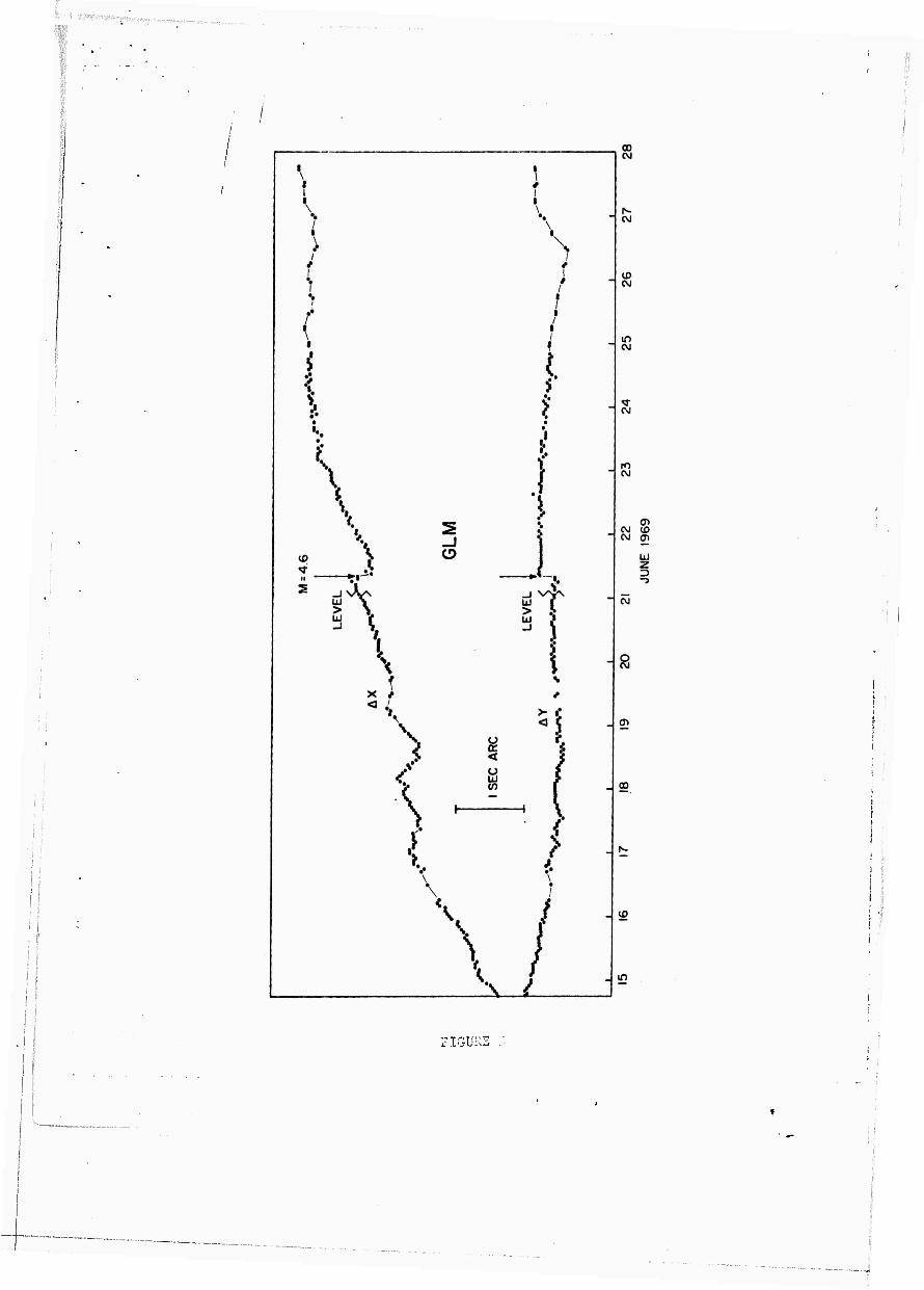
The next observations, after the initial stabilizing period, was that
the feedback signal showed much higher variation on the X component than
on the Y component (see Fig. 2 and 3, GLM-X and Y). Also occasional recording

«
of the U^X and ¥ traces (afttr il)@ IMn^fwy d«t*llfier) sli«^ed ysuall^ it^di
hlglisr "baeiigmmt)" n^ie^ «it the X c«*»|H«8iet«i (§&#■ Fig. AA, It). Houevef il
vas not until }i3v«MM*r t9§9 wtwn ui« r^cordrd HrM and plotted all data toi^thor
(•ee Fig. S) chat the X ewptment uas doCInitely identified a« retpondlng
to «ome unknown sourco. Tho tolometer syacota, the eleetronlcs and tectonlcly
generated tilts wore ruled out, bocnuse the trdnstnisslon channels wore
independent; phonollnc-rndio or radlo-phoneiinc-rfldlo links for each station
and distances between stations (see Fig. 1) and/or orientation of the bore-
hole package axis (GLM-X to North, PAX and MCK-X to FMst) as well as location
with respect to Al ;kan tectonic £eatures made a common source for real tilts
highly unlikely.
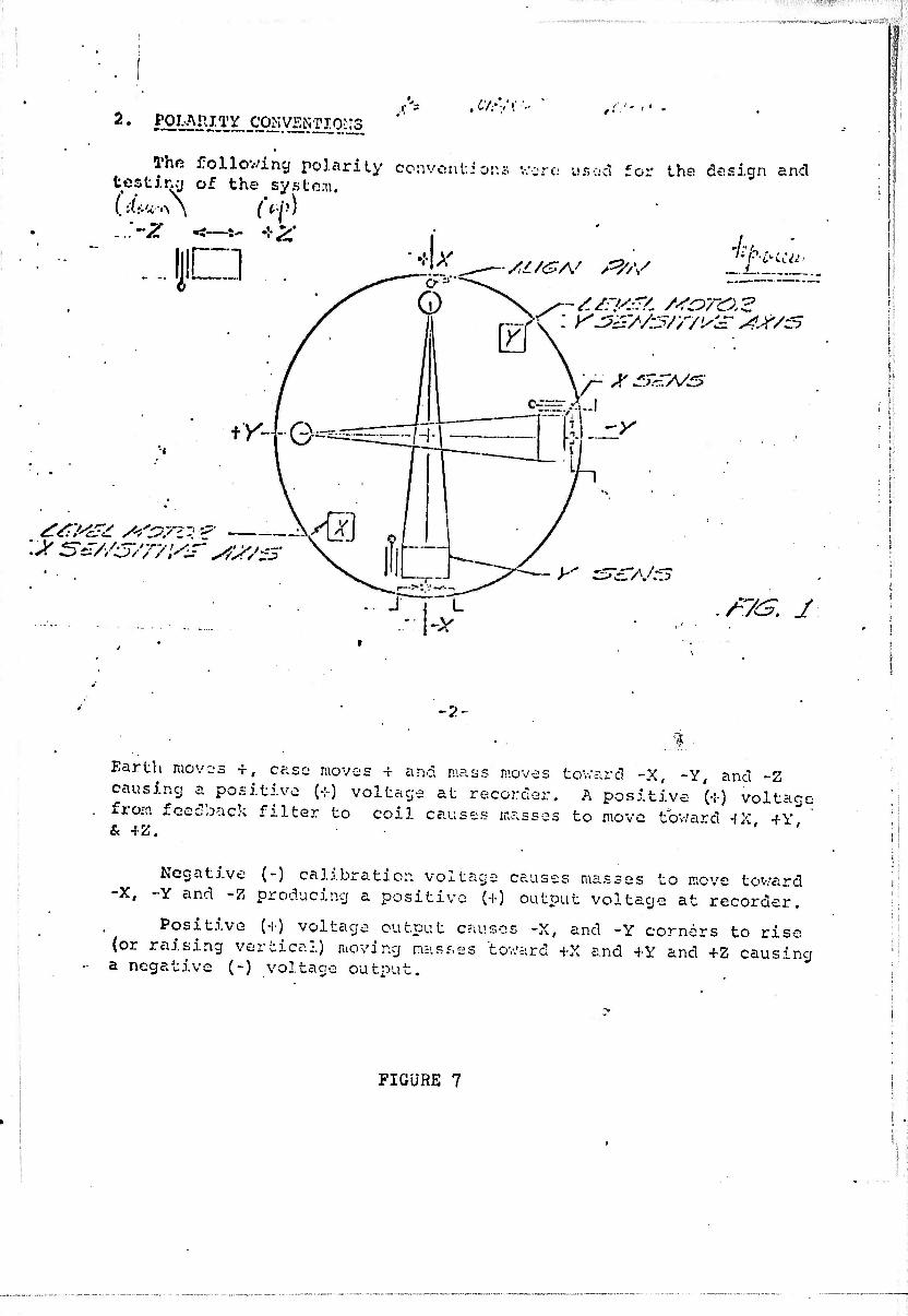
Then the mechanical construction was scrutinized: the X component
leveling is achieved by leveling the outer gimbal ring. See Fig. 6 A, B
for a picture of the outer gimbal ring and its drive motor; see Fig. 7
giving the layout of the horizontal components, associating X with the
outer gimbal ring (this was taken from the Teledyn, Earth Science Division
Engineering Report No. 615-1266-002, dated 28 January 1966). So only a
tilt of this outer gimbal ring with respect to the axis of the borehole
package could be blamed for the large variations observed. A tilt of this
ring can be obtained by compressing or stretching the frame member holding
the ring (the arm of the leveling drive remaining at constant length). The
only force that can compress (or stretch) the frame, including the outside
protective shell, is a pressure variation on the assembly, because this
assembly is sealed pressure tight with 2 large "0" rings. If the exact
cross section of the two frame members and the outer shell were known, the
tilts resulting fesm such a variation could be calculated. The long-term
J

«iia*»5plteflc virlst lo^i are of tli@ m4$f of 10P m bars «r lO^/fif/cf» | ili<*
total effective sorfari« Is the Efface cross »tctlo» of the insir»m<@fii
package (10 Inch dlas^ter) and the coenpresston of steel Is of the order
-7 2 of 4.6 » 10 per kg/cs« pressure Imrease. Since the oyter shell plus
fra^e section Is relatively seall c^mp^r^d to the total effective cross
sect ton of the package, litest figures seen io indicate the right order
of wagnltudo. In addtii^n, the lever ara (distance fno the ginbal ring
rotation axis to the level drive attaehtPent) is about a factor of 3 to 4
shorter than the distance frotn the b»»tii i plate to the rotation axis
(the length of which is variable with pressure) so that the tilt (as
expressed in radians) arc amplified by that factor.
In order to obtain n "scale" factor, the hourly barometric pressure
values were obtained from the ESSA Weather Bureau at the Fairbanks
International Airport and compared to the hourly values of tilt at the
GLM station. Figure 4C shows a few minutes recording from the infrasonic
array element located at the International Airport. No coherence can be
expected with the Gilmore X at the same time (Flg. 4A). Since the infrasonic
array element is in a low wind area, and GIM on top of a hill , an increase
in amplitude of about a factor of 2 does not seem unreasonable in this
frequency band. It was judged from the comparison that the distance be-
tween the two sites was insignificant for the long term variations.lt also
should be mentioned that 2 layers of about 5 inch foam rubber (each) were
present when the measurements were made for GUI. In PAX a hard foam plug
had been cast, but was not air tight along the casing because the casing
was too cold for the foam to perform its normal binding. In MCK the hole
was only covered with some wood and dirt. On the other hand when the outside
shell is tied to the package, the gimbal ring support member will be under
tension the outer shell under compression. The total barometric pressure
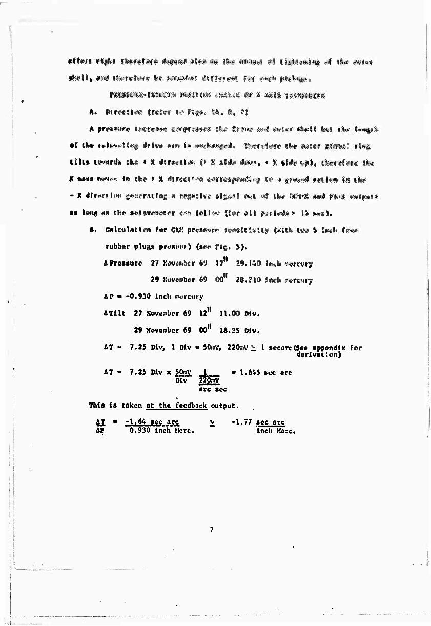
A. PI reel ID» Crefvr i«» fl$«. id, ft» ^|
A ftreSfttf« 8!■»«»«**# f#)iif«f«*♦*.* llb^ f« wtw' «ml ^|## ^Nfll !»¥< iBw' i*«ii i-
of t8i# relipVtfltPd ^fiv« aiw I» wm$mm$€4o 1l«'ft-f«f# UN-- Mit* ii«4i#t rlim
Ellis r^'v^fj» ik# « % 4lf*ftUm i* % si#« 4**^, * % §i<**> ^|, ll*rf#f«Nfc i^
X mst ^«vc* In ch# * X dirges "i^ c^rret^^li^ ?<« j g^^^ m^ts«^ im II*F
- X dtr^cft^n geet^raiins a «i^#ii%«? sigo^l ^»i «*f I8M# jtt^'i #»l fg«! MI^I*
at long d» the tols^wi&ior cm (OII^M |f«*r all f.?f 1^* * II tf«|.
B. Cilculatl«M) for Cü« pr^swrt« ««pslilvlsf (^1(1« sv-... | i«f|i jo,.-.,„
rubber plugs present) (sec rig. S).
A Pressure 27 KovftaWr 69 II 29.140 l^h mtsurf
29 ^uv6»ber 69 00 28.210 Inrli «nerctiry
AP ■ -0,930 Inch mercury
ATilc 27 November 69 ll1' 11.00 Dlv.
29 Noveobcr 69 Do" 18.25 Dlv.
AT «* 7.25 Dlv, 1 Dlv • SOnV» 220»V1, 1 secane(Seo sppendlx for derlvsclon)
IT ■ 7.25 Dlv x 50aV _! - 1.645 sec arc Dlv 220mV
arc toe
This Is taken at the feedback output.
AT ■ -1.64 sec arc * -1.77 sec arc AP 0.930 Inch Merc. ~ Inch Merc.
■
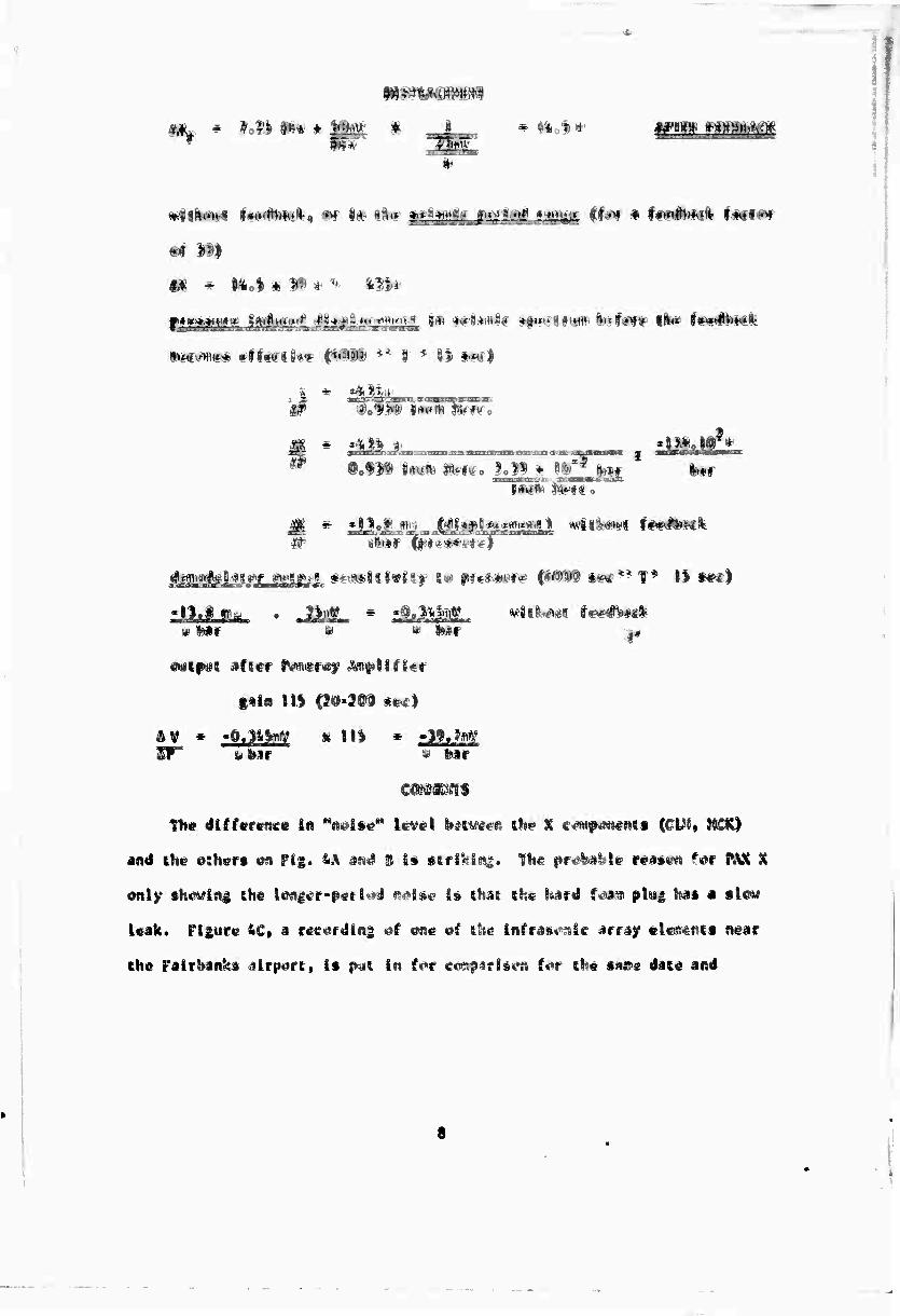
• «U% » »imio?*
§#1« 111 ^t»'3@D s&£)
SF* UMT ' •* Mt
cowgagii
Th« difference in M<i«lteM level b^i^een tl«e % e«ttf4««eAtt (GIJ5» JttCK)
and the «nhers en Fig. &A JN^ S If ttrl^lti^. the pr^ä^le reisen f^f PAX t
only shewing ehe lengef-petlt#d ml&e I» (hat the hard f^aiü plug häs a SIISM
leak. Fliure &C» a ree^rdln^ «1 «»ne «f the lnfras»^lc array eles«nts near
the Fairbanks airport» Is r^i In f^r e«i^rls«*n f««r the saa^e date and

covering about 1A mLnutes oC the recordings of Figures 4A, B, The pcak-to-peak
amplitude on the Infrasonlc record Is probably between 15 and 20 U bar (clipped
on the record) obtained In a rathor calm area.
The amplitude of the GLM K trace corresponds to about 1.5V x 1 U bar 2L 40mV
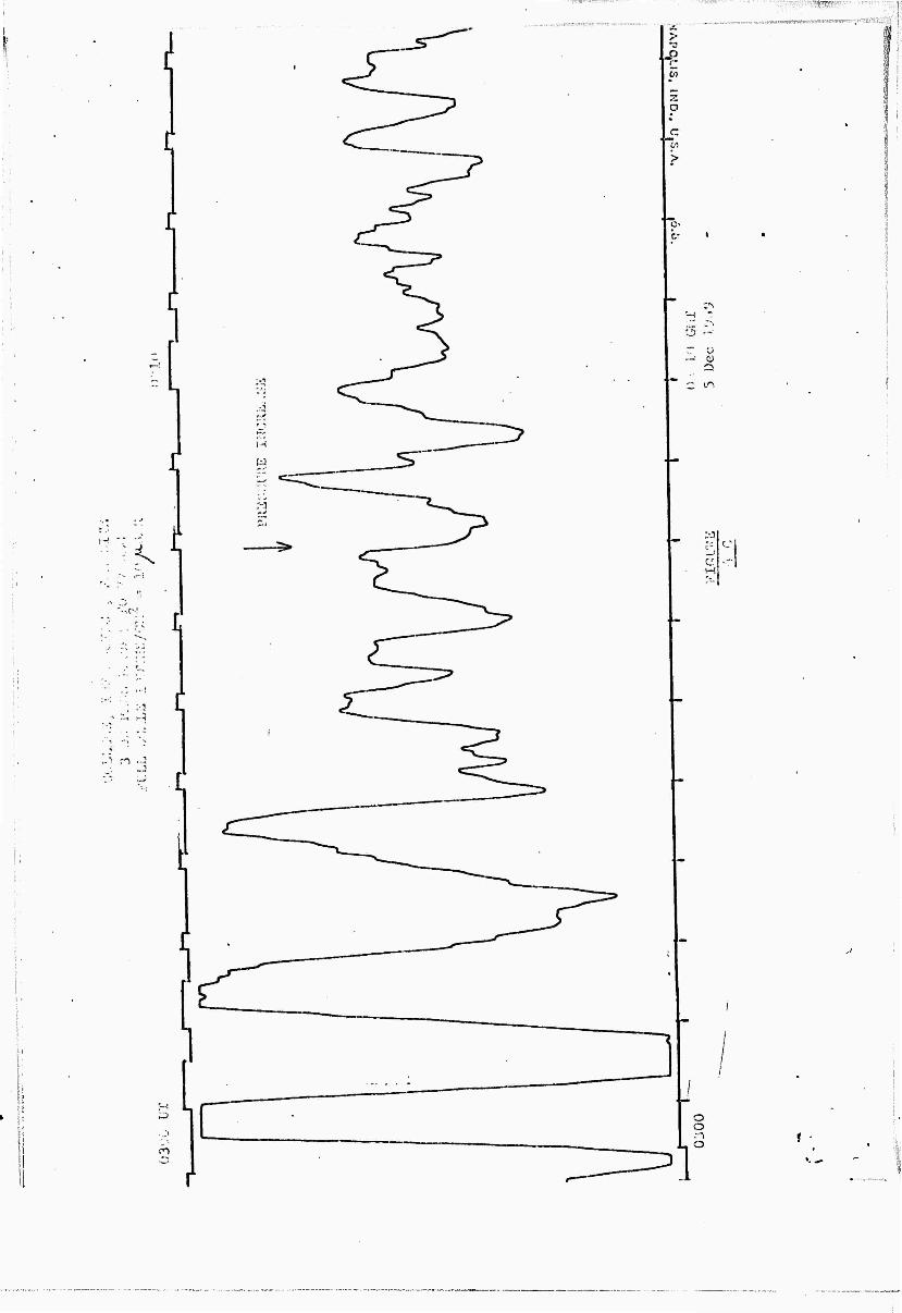
38 wbar. Figure 8 shows a longer-type barometric pressure oscillation
(probably gravity waves) at MCK, situated in the Alaska Range. For comparison,
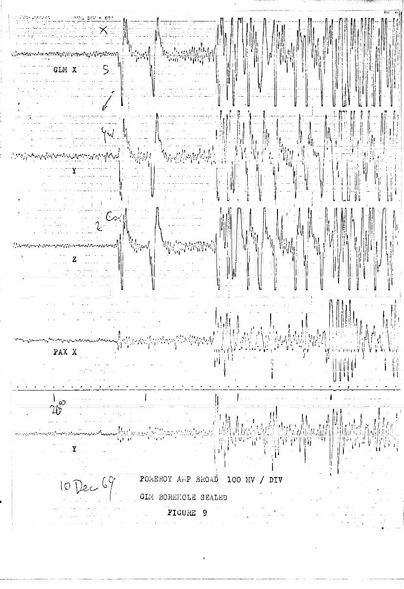
Figures 9 and 10 depict two earthquakes after the GLM borehole has been
pressure sealed, and show the low noise level on X.
CONCLUSIONS AND SUCfJESTIONS
In conclusion it can be said that the LP-X component of the USO package
forms an excellent microbarograph and barograph with a response from 15 sec
to DC if there Is no earthquake recorded.
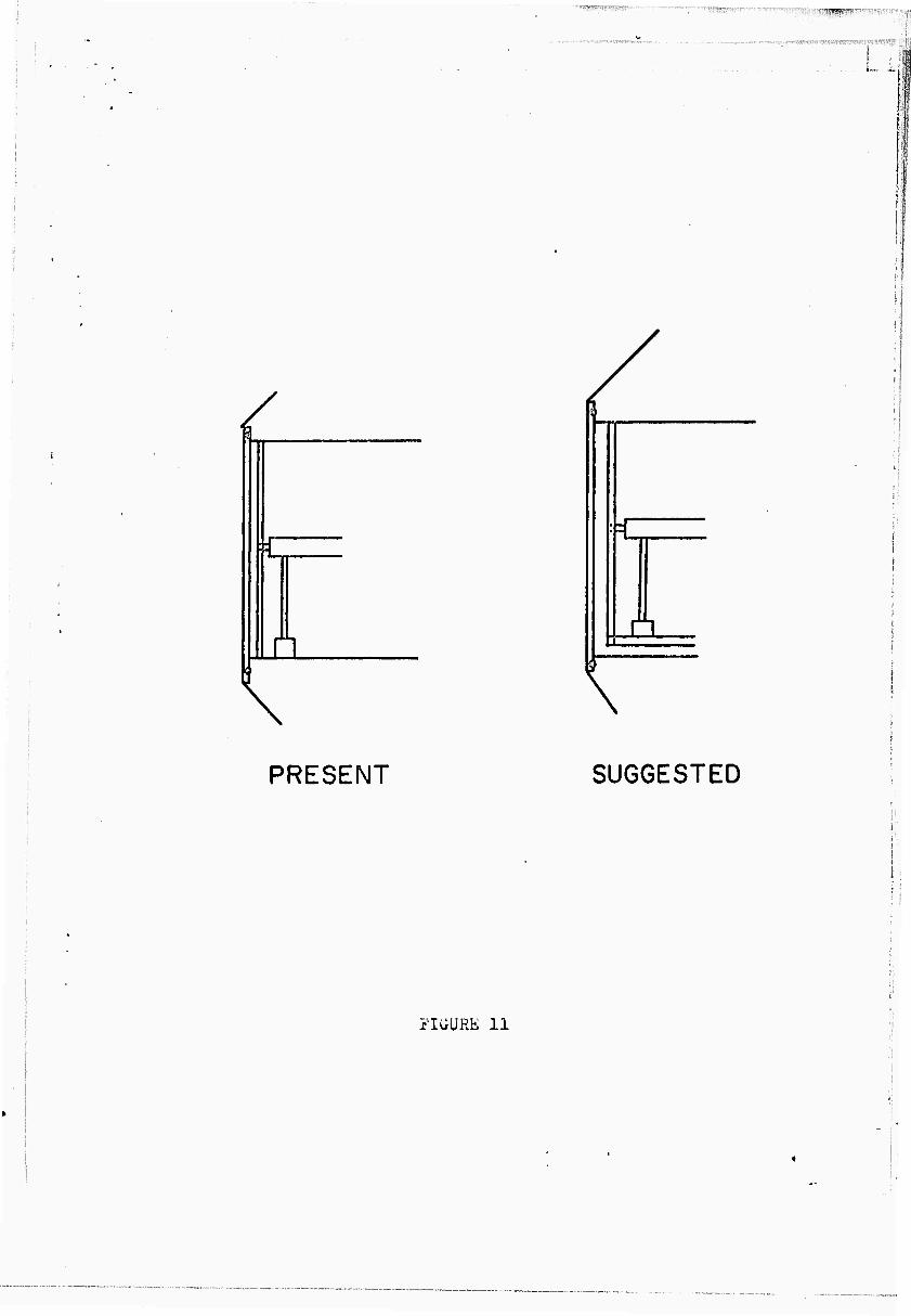
If the package were to be rebuilt we suggest separating the frame
members holding the instrument package from the outside protection. This
can be achieved so that the outside shell with its bottom plate docs not
mechanically connect to the plate at the bottom end of the frame members.
The latter plate holds the leveling drive motor and if not isolated, will be
responsible for transmitting atmospheric pressure variations.

: I,-
■ i:
i
APPENDIX
TILT OF A HORIZONTAL PENDULUM
If a simple horizontal pendulum has a length 1, with its axis of
rotation perpendicular to the vertical,and initially at "o" position,
a tilt of the vertical will produce an excursion X for a tilt of
r radians.For a pendulum with only a small angle between the vertical
and the axis of rotation,and corresponding free period T, the equi-
valent length of the simple pendulum is given by:
1 = 7-2 Where g = earthgravity (981cm/sec )
For a 15 sec pendulum the equivalent length is 57.3 meters. A In
displacement recorded at the transducer of a 15 sec pendulum therefore
corresponds to a tilt of •■vV, ;m • radians or 1.745x10" raöians.Since 5 r. jJm _g
1 sec arc = 4.ci5xl0~ radians, a 1 sec arc tilt produces x ^VCY'IO-S I1
- 276 p. displacement on the transducer. The feedback reduces this
displacement by a factor of 31.6 (30db), Isec arc tilt produces there-
fore 278^/31.6 or Ö.Ö0 ji displacement after feedback.
With a demodulator output of 25mV/u this finally gives
220 mV signal / sec arc tilt ( after feedback )
If the tilt is in the direction perpendicular to the plane containing
the vertical axis and the axis of rotation.
\
10
REFERENCES
Sandia Laboratories, U.S.O. (unattended seismological observatory,
final evaluation report); SC-M-68-60, April, 1968.
Berg, Eduard; Sperlich, Norbert; and Feethara, William; "Large
Aperture Seismic Telemetering System for Central Alaska"; Scientific
Report, UAG R-188, Geophysical Institute, University of Alaska,
May 1967.
ACKNOWLEDGEMENTS
This research was supported by the Advanced Research Project Agency
and monitored by the Air Force Office of Scientific Research under
contract number F-44620-68-C-0066, and contract number F-44620-70-C-0031.
11
. , ■:■ -:■■,
_,,.P.......... -v-:'-';,:-j^.t;.-.t.^,-r..nS.,«.;tJ..._-,,..-,. .,....,.,;.„..,.., „ .......-^^*,^.,.^.^^J-...■[v.^,-i;-r:r^r.r/--■'■■ ■■.■-^'■/-■■■•^.•::i>'''t-''','!!
/ ' FIGURE CAPTIONS
1) Seismic network
2) GLM, PAX Tilts 30 July to 8 August, 1969
3) GLM-Tilts June 15 to June 28, 1969
4) A and B, GLM, PAX, and MCK Barometric Pressure noise on X components
C. Microbarograph - Infrasonic recording at Fairbanks
5) Tilt on X components and Barometric pressure at Fairbanks International
Airport
6) A and B, Instrument package
7) Layout of horizontal Seismometer components (Top View)
8) Typical Barometric effect on MCK-X
9) GLM-X noise background after the borehole was sealed. (The coupling
between the three components has since been removed.)
10) GLM-X noise background (Coupling between Amplifiers removed.)
11) Suggested changes in the mechanical arrangement of the instrument
package
!
!
12
■-■:■
!
\,
Fig. 1
SEISMIC STATIONS
GEOPHYSICAL INSTITUTE, UNIVERSITY OF ALASKA
© TELEMETER STATION 0 BOREHOLE STATION WITH TILT RECORDING
W i v
C/.,.f„„.„.,
\r*,:r \ C V\A '
u t-t.'^.«.
'>^ ■ ^i.<L\. . ^^T V ^:^i y Q _V0 GIL ■"•^P' -'
/^l6#^ ^K^7^ P^^%^ ^fevt^-
^ «<"".„,
.s-
*•*■:■
0 ' JV^-^^I
«» r
fo» sut jr ü. J. 'i!o.03h:f. tjrm reseRiL :T '. "O: j» « V this 373 S is. 0. c.
Fig. 1. Seismic station;
ii-.-7«,,i!,r.,i;i-^i-'"'«wr,»^,.j.v,,„ iKi»i>wiwnwi«o,*»«!(rB^&'y
\
LJ s ^ A J >. ^ "/ <•'•<
*, _j \. •••. /••.. - ^ / \ ;i
S <. k. - .• • • *.
i i
• ( A'- /. •• J . K x < ^ 0 V ^
J « X i <
• ^ CL * «
1 J .1 o a: / i <
ü t S \jj C/3
> , - , t < 1 1
% : • •
00
- N
- &
- in
- ^r
iß g> i- <n Z) o Z) <
- ro
- CVJ
ro
O ro
ID "3
7Tnr-7 ■}
riGu;

,*^*f.'>;*r.~C^'~r-m-.-::?' ■';,:'.•■ ■'. :. "IV.;! tr■l;^'>(,^■^•'V"■-■?T'*^'T,
.■■<>'
... j...
■-—-- —-in
^H%i§4MPw^ GLM X PÜHEROY AMP BiiOAD lOCKV/SI-iALL PIV
POMKUBBKR PLUG
^'Y^w^^
GLH y
y'>,-~f'''J>\^\\'^V-\;'S^^,J'Krr^^Sv'S\t'^^y-w^
Ulu'l Z
'"■•■■•" ■•'■ '^-■^.^'.'■-'.■.•'■•.-r.^jv.-' ^•■■^•V^A\y^ _^^ ^'v—J"^-.'--.
ü^ CO G.:I p'-'^C 62
10 MIN
PAX X
„■--/-.•, .',.N -»v- *-,V-''AV.V'--'--MW,-V.--, ■■%-/v.- -,--v*- .•y,-.- ^ V- .\v-».v,V^^-,V' '<*j.-:r'*-.'.'~'-'.':rs~~:?. ■', v,„v^,V--r-.«-'.'lv ,.-v.1Vv-~"-V'V
PA/; Y
FIGURE 4 A

..^^^^A^/HVV/V^^vA^^
PAX X
'0^ 00 DKC569
'■^>i7^''v-V'^A,"'^'^'rt^
PAX y
M44(W m Jl! Ki44^mlM^^J^ Ah
MCI: x
^^'^■''A^y^A^*^^^
MCK Y
yx^-\rtr'\K\i^'^^-^^^^^ V-. .S-AA.^.^V^Y'-.V -»•',v-'--\.Vv-v';
MCK Z FIGURE 4 B
L_i j »^, t > > > * > i__L. i i i i i * >
V-u-^~V-''",'^v's,A"v-,v^V,,,^/.'lv.,-V'\'.. • 'Ay,~'\.'.--*y\:'y:. •-'••.• .••v.
±
T' T;-vp'" ^r^r T"'S

1
■
SECARC TILT
BAROMETER (INCH MERCURY)
6.0-
4.0-
28200
■28.600
2.0-
29.000
KAMCHATKA M = 7.5
.. MCK
BAROMETRIC / PRESSURE /
/
N.
/ 4^-4-4 "0.
29.400 PAX®
A \ t\ f\\
AN. AM' A V/ / .-•■• ® /
V.
30.000 / „^-/ >-.-.°L.M ® .
//
/
/ X / \. •^/
PAX ®
17 23 NOV 1969

■ ■ ' ~".
i ■-■-■■ -. * '.^--t •*■■*•■*& j A-.A.f'&pi-.m&n^ fr*^
t §
i • -
^ & **
S>* ^N

O-RING
1%
n< ii
FKAhü i'liiaBER
\ r OUTER
GIi\BAL HING
> y. i \ ■
:\::<
\ i
Y-MASS
r;
i-;: LEVEL' Fj DRIVE sr- ■
: 1-.--. . '-
i ". : f
, FRAME MEMBER
f^x.y- if. r
i
u ^
f-;£
LOWER PLTEORH
^ ^ ^ ^ ̂
^
FIGURE 6 B
, .,
I. 2 • POI-AHITY CONVEiNTIOMS
.cz/yr- ' • -. >
The follov/incj polcirity convonl-.ior.i-. v/crc- usocl for the design and tcstiM of the system.
I
fy^fQ^
xfr5H>V^
~y
y z^c:/\h3
WG. J
-2-
Eartli moves -f, case moves -r and mass moves tov/ard -X, -Y, and -2 causing a positive (-;-) voltage at recorder. A positive (-1) voltage from feedback; filter to coil causes masses to move tbv.'ard -fX, -fY, & +2.
Negative (-) calibration voltage causes masses to move tov/ard -X, -Y and -2 producing a positive (-!•) output voltage at recorder.
Positive (-i) voltage output causes -X, and -Y corners to rise (or raising vertical) moving masses tov/ard -rX and +Y and +2 causing a negative (-) voltage output.
FIGURE 7

i :.
t*i • 1 ^V^S-r/. ^iS^sW^^'r^~^\^^^^^_^^ ^-^Av,^,
-L— .PAXX.
K, IVVU^-VJAV^.* ̂ /^^^'^V^.^^ v..,v
POMEROY AMP BROAD 100MV / DIV-
V
f. •*•■
:r':PAXT .'.T;"'-'.r^I■;■;.'..-;-.--■••-;:- -^ ■—.
^''.'••■W-r-'-'/'f'; ^w<-rt--J-W',^A^
MCK X
MCK Y
/ \^
I
J.^^
• -l-'r
MCK Z FIGURE 8
^^PK^M^-^^-H-^^^-^^^4^,-f4-+-H^'^T
. ^.--T,.,..:.,,....^..
X ---■—--^^ ]--\\. ,
GLM X 5
//
PA-
p i i
'l ■ ■
:i| ■jl i !! if
'.-.'.vv.-.—J-^.v
.:,.:,..;v , i It'*
I'M n n
l':l !(
Ml; U It
M.
i1
p
■ km li
ii
i' i
; I
.! . J i- i
i
I i,
Hi |i i!
PAX X -• i,0v: ■...'.■'AV,:^'AV-V ••■'•••■■Mi'/^V
) ' ■iiM.1, >* ■ • i
i, ii I ', i M ! I il !■ ! rt .'! I ' \ M . i . ,il ''.i r i u.. r« ^,.■,■ : l '• -ii..'Jin ,i.i'J, : •i'!i^:,J! ■ ; \ ■" :;:'"-lfJi!'.,'''ii''i!r; r'ilif;.-.'] '
in'-'i f\< -' • t"1 r r , '• ui j,^ ^. , . ,■,
Hi
CO
V--0,V'-.-.V..''.\i •-^'-^.■'.-.'V.^.-^^-V'-»"-'- l»v-^Av.* ^.t w
• '—* ** ■ A^ Jfc*. ' ' ' . " - *. V * '
n « . ■ 11
V i' .•
i 'ii
II1
■i ■,. 1 U; ' :\ * ii; .i^i'liriii'li
i i
l..,i..Ll 1 A
! ! -"..il',' 1 fil:; ■'::
ioT^-.-cf POMEHOY Ai-'1P BROAD 100 MV / DIV
GLM 3ÖR£?:0L3 3EALKD
FIGUxHE 9 . . '

n n ir
i L til . i
<Mr^:W^
GUI .'■ % POIuEHOY AM? 100' MV / DIV
lu
!1, I mi III! I
II ffiilü
i ; • ;r;.li,
yyüsyitiu U L i J J i
iriirf rj p rTT'
Il hi:
■-^\f^^A^^^*\j\jS^s.^Xs^'-A^~V\\r^:^^'^^^^ "-'
'X( Mnlit f i
llllil ■W m
II ;-:iiM
iim
1;
I;1!
'- ,1, 'li
' iil!
:.., Z
«'| I «.■.■!
111
,,••11,71 !!r III;!,,' 'Il < !;iil i
!
I Uli
,1'' ii i
iii IMM
y:^ 4JAW7(0 JT- 17 ^0
/..'■
ÜSCGS £PIC£UIh;R 251-1 102S ORIGIN TIMS 170042 hAG. 8.0
FIGURE 10
s
ft
a \
a
\
PRESENT SUGGESTED
FIGURE 11
UNCLASSIFIED ■niritv Classification
DOCUMENT CONTROL DATA -R&D 'St-curjfy ctttssifictition at title, hady of abi-trnct and indosing annotation nmvt be entered when the overall report Is clitssitied)
i Of-IGINä TING AC Tl Vl T Y 'Corporale flulhof;
Geophysical Institute University of Alaska College, Alaska 99701
2a. REPORT EECURI TV CLASSIFICATION
UNCLASSIFIED Jb. CROUP
3. BEPOBT TITLE
The Effect of Barometric Pressure Variation on the "U.S.O." Long-Period Seismometer
4 DESCRIPTIVE NOTES (T)pe of report and inclusive dates)
Technical Report tUTHORiSI fF/rs( name, middle Initial, last name)
Eduard Berg Ronald Rasmussen
I
6 REPORT DATE
March 1970
7a. TOTAL NO. OF PAGES
24
7b. NO. OF HEFS
F-44620-70-C-0031 h. PROJECT No. y-44620-68-C-0066 ARPA Order: 292 Amend No. 54
'"• Program Code: 9F10, PEC: 62701D F-44620-70-C-0031 - ARPA Order: 292 Amend
'Hi, Pt-ogram Oode: OFlO. PEC: 62701D
9fl. ORIGINATOR'S REPORT NUMBERISI
9b. OTHER REPORT NO(SI (Any other numbers that may be assinned this report)
IP DISTRI BUTlON ST ATEMENT
This report has been approved for public release and sale; its distribution is unlimited.
11. SUPPLEMENTARY NOTES t JitSPONSORING MILITARY ACTIVITY
-•' United States Air Force Air Force Office of Scientific Research
The particular manner of mechanical construction of the Long-Period U.S.O. package is responsible for the pressure sensitivity of the LP-X component. The effect seems to be linear with pressure for periods larger than the seismometer period and short compared to the feedback signal time constant. Under the particular setting of the Gilmore (GLM) installation, a pressure induced dis- placement of the x component is Ax = lilJmu (without feedback).
Ap pbar
Since the pressure induced displacements are considered as very undesirable noise for the instrument as either long period seismometer or as tiltmeter the borehole was pressure sealed and the effect removed. Records are presented to
" demonstrate the effect.
(
DD FORM 1 NOV «S 1473 UNCLASSIFIED

:;-' ■ ' '■ |; ^ ■!':i' '■" -'"""■"■ : ! ':- "■ ' '■''■' .■' ' ■'■' i .■■■-■- --■ .■!-,, ,-..-..,. ,.,.,^-^'^RS^^f^W^^V'^W^^^-.:.----
"unty Classification
DOCUMENT CONTROL DATA -R&D m' flniiiliculior, ol lillt, hntly ot absimcl und indexing annoinlitm must br tnlertd ivhon »if oveialt fi'pofl Is clnssititd)
C^ICI'. A*NC ACTIVITY (Corporate author)
Geophysical Institute University of Alaska College, Alaska 99701
2«, RETOnT SECURITY C U A fsi Fl C * TION
UNCLASSIFIED 2b. CROUP
1 3 RfePORT TITLE
t V
The Effect of Barometric Pressure Variation on the "U.S.O." Long-Period Seismometer
f.iPTivE NOTES (Type ot report and Inclusive date»)
Scientific. . . . Interim oi-.oRisi {First name, middle Initial, Ian name)
W5 w Eduard Berg ^^ Ronald Rasmus sen
OKT DATE
1970
C^fojEcr NO. yö52
0270113
7«. TOTAL NO. OF PAGES
24 7b. NO. OF REFS
»a. ORIGINATOR'S REPORT NUMBCRISI
8K OTHER REPORT NOISI (Any nlher number' thai may be aselgned this report)
AFOSR 70-08 02 TR U CIS T Rl BUTION ST ATEMENT
1. This report has been approved for public release and sale; its distribution is unlimited.
5U~I'L EME.N T AR Y NOTES
TECH, OTHER
i 'i A «1-.T ^ t r 1
12. SPONSORING MIUTAPIV ACTIVlTV
AF Office of Scientific Research (SRPG) 1400 Wilson Boulevard Arlington, VA 22209
Tlie particular manner of mechanical construction of the Long-Period U.S.O. package is responsible for the pressure sensitivity of the LP-X component. The effect seems to be linear with pressure for periods larger than the seismometer period and short compared to the fendback signal time constant.y Under the particular setting of the Gilmore (GLM) installation, a pressure induced dis- placement of the x component is Ax = -13.8mu / ... ^ r ,. , v ' r — (without feedback). Ap ybar
Since the pressure induced displacements are considered as very undesirable nois^; for the instrument as either long period seismometer or as tiltmeter the borehole was pressure sealed and the effect removed. Records are presented to demonstrate the effect.
i D D C
lUi ,PR 9 MO
DD ^1473 UNCLASSIFIED Sccunlv Clas^ifii-alinn
30
M-* uriv, n.tS«': i l;-dt .>n
K E V WO BO»
Alaska
Barometric Pressure effect on U.S.O. Long-Period seismometer
Sealed borehole
Microbarograph »
V
UNCLASSIFIED
'!- ■ Security Clacsificstion
Recommended