Guangzhou Waytroinc Electronic Co.,Ltd http://WAYTRONIC.RU
1
The Manual of WT5001-48L Chips and Modules1、Product description and features1.1、Description of WT5001 chips and modules
WT5001-48L is a high-quality MP3 voice chip of OTP,8-BIT CISC; supports MP3 decoding, supports WAV
format; with a rich set of peripheral interfaces; an SPI ,supports DMA; drives 16Ω headphones; with real-time clock
and calendar clock modules; standard RS232 serial controlling. Dual channel LDO, 5.0V-3.3V; 3.3V-1.8V; low power
consumption; standby current 60uA; fast response of controlling and playing , superior in similar products; suitable for
the occasions where need to replace the voice or where a long time, high quality voice are required.
WT5001M01-16P, WT5001M02-28P and WT5001M03,-28P three MP3 modules are high-quality and stable
semi-finished modules developed as WT5001-48L is the master chip. All three modules have the minimum system
functions of the WT5001-48L, come with the SPI-FLASH as a storage medium, 1W amplifier; serial port controlling
functions, download music files online. Based on this, each has different features, and is flexible with the secondary
development in a variety of situations or used directly.
Our company can provide development of various functions for customers.
1.2、Example of application
WT5001-48L chips and modules can be used in automotive electronics (theft alarm, reversing radar, GPS
navigation system, electronic dog, central lock), intelligent home systems and home burglar alarm, voice navigation of
medical instruments, personalized voice player, household appliances (cooker, rice cooker, microwave oven),
entertainment devices (amusement machine, voice advertising machine) learning model (early childhood education,
children's audio books), intelligent transporting equipment (bus stop, parking systems), industrial control field(elevators,
industrial equipment), voice instructions, fault code language interpreter, toys and other fields.
Suitable for: the occasions where need to replace the voice or where a long time, high quality voice are required
.
1.3、WT5001-48L voice chip features
·WT5001-48L chip package is TQFP48, module
package are DIP16 and DIP28;
·8KB OTP,8-BIT CISC;
·DAC & MP3/WAV Decoder, drive 16Ω headphones,
SNR=93dB,support MPEG 1/2/2.5 Layer3, support
MP3 decoding, 10 band equalizer to adjust, 32 levels
volume to adjust, support WAV format;
·One SPI, support SPI-FLASH download music files
online;
·Support SD card 、U disk、SPI Flash to store;
·Support 4M、8M、16M、32M and 64M SPI-FLASH;
·Playing content in SPI-FLASH is default when
power on
·SD/MMC/MSPRO host Controller, support
maximum 2G capacity, playback the contents of SD
card controllability, can copy contents of SD card to
SPI-FLASH offline;
Guangzhou Waytroinc Electronic Co.,Ltd http://WAYTRONIC.RU
2
·USB Host/Device, playback the contents of U disk
controllability, can copy contents of U disk to
SPI-FLASH offline;
·Change playing mode when power on by setting
iSound.mp3, the mode include: auto play or not,
single cycle or not, all songs cycle or random play;
·Three method to copy, include: press key power-on
to copy、 playing key A、B to copy and serial
commands to copy;
·Press to copy function key, there are functions of
pressing key power on to copy and pressing key to
play
·A、B mode function key, there are functions of A、B
copy and A、B mode to switch;
·One to one playing key, control to play voice of
corresponding address, there are two cycle mode to
choose.
·ADC key, support five standard MP3 function key,
realize that one pin control more key;
·Standard UART communicating interface, default
baud rate 9600, control by commands of MCU or PC
serial, stable and efficient communication
·Can control to insert music to playback
·Can control to play compositely and continuously
·Can set RTC, can set timing time;
·fast response of controlling and playing, superior in
similar products
·Operating mode of setting memory with EEPROM,
identify the mode automatically when power on,
when switching mode ,the light flash indicate that the
mode is switched and the signal of BUSY goes low.
·Come with a reset module internal;
·RTC real time clock and calendar clock module;
·A signal of BUSY as output pin, it will be high when
audios are playing, and it will be low as normal;
·Play mute when the current is lower than 39mA, SPI
play time when power on is less than 0.8s, superior
performance;
·Support FAT16,FAT32 file system;
·Work stability for long time, strong ability of
anti-jamming
·Dual channel LDO, 5.0V-3.3V; 3.3V-1.8V
·Support a variety of voice development programs
flexibly.
1.4、Feature details of WT5001-48L voice chips and modulesWT5001-48L voice chip is a powerful OTP voice microcontroller chip. WT5001-48L makes that voice chip no
longer find suitable external microcontroller circuit for the way of controlling, highly integrated single-chip technology
is sufficient to replace the complex external controlling circuit. The operation is simple and easy to understand, the time
of using and secondary developments are greatly reduced.
SPI Download online: Download through the downloader and the compile software, download the music to the
SPI-FLASH simply and easily. The downloader is easy to use, and the compile software is convenient to operate.

Guangzhou Waytroinc Electronic Co.,Ltd http://WAYTRONIC.RU
3
ADC standard keys: An interface can control five keys , save I / O resources; fully ingratiate the function of MP3
in market, that play / pause, stop, last song, next song, volume +, volume - and so on;
Press to copy function keys: The key function of normal is: short press, is for the next one, when play the final
song, back to the first song ,and the playing mode is single cycle mode; long press, is copy function when power-on ,
first press the key and hold before power-on, after 5S power on ,BUSY indicator flashes (said to enter the copy),
release the button until the BUSY indicator stop flashing and darken, copy success.
A 、B mode function keys: Short press A key to select last song, long press A key for 3S to set to A mode; short
press B key to select next song, long press B key for 3S to set to B mode, the key is active low. Model A: auto play
current songs (Memory) each time when power-on, play it once and stop. Mode B: play the next one (Memory) each
time when power-on, play it once and stop; when play the finial one power-on, then start to play the first one when
power-on next time.
One-to-one function key: When DATA14 is high, DATA16 \ DATA17 \ DATA18 \ DATA19 correspond to 1, 2,
3, 4 pieces of voice, low pulse trigger and play once then stop. When DATA14 is low, DATA16 \ DATA17 \ DATA18
\ DATA19 correspond to 1, 2, 3, 4 pieces of voice, when low to maintain ,the playing mode is single cycle, when jump
to high it will finish the current song then stop.
UART serial port control: Standard serial port communications protocol ,by sending a command to control that:
specify music file to playback, switch memory, switch cycle mode, music insertion, a combination of songs to playback,
set and read RTC, timed wake-up trigger, etc.;
ISound.mp3 document settings: Set “iSound.mp3” file which is the content of the final position in SD card, be
copied together to the SPI-FLASH, which can be set to change the mode that if play or not when power on and the
cycle mode.
2、Selection guide2.1、Function table
Model Package Size
(mm)
SPI
download
Serial
control
ADC_
KEY
SD
card
SD card
socket
U
disk
One to one
key control
A、B
mode
WT5001M01-16P 16PIN module 20.9*19.6 √ √ √
WT5001M02-28P 28PIN module 36.2*19.1 √ √ √ √ √ √ √
WT5001M03-28P 28PIN module 36.1*19.7 √ √ √ √ √
WT5001-48L TQFP48module 9.0*9.0 √ √ √ √ √ √ √
2.2、Absolute maximum rateParameters Mark condition Rated value Unit Note
Supply voltage VDD Input -0.3V-5.2V V
Guangzhou Waytroinc Electronic Co.,Ltd http://WAYTRONIC.RU
4
Operating temperature Topr - -30—75 °C
Storage temperature Tstg - -20—55 °C
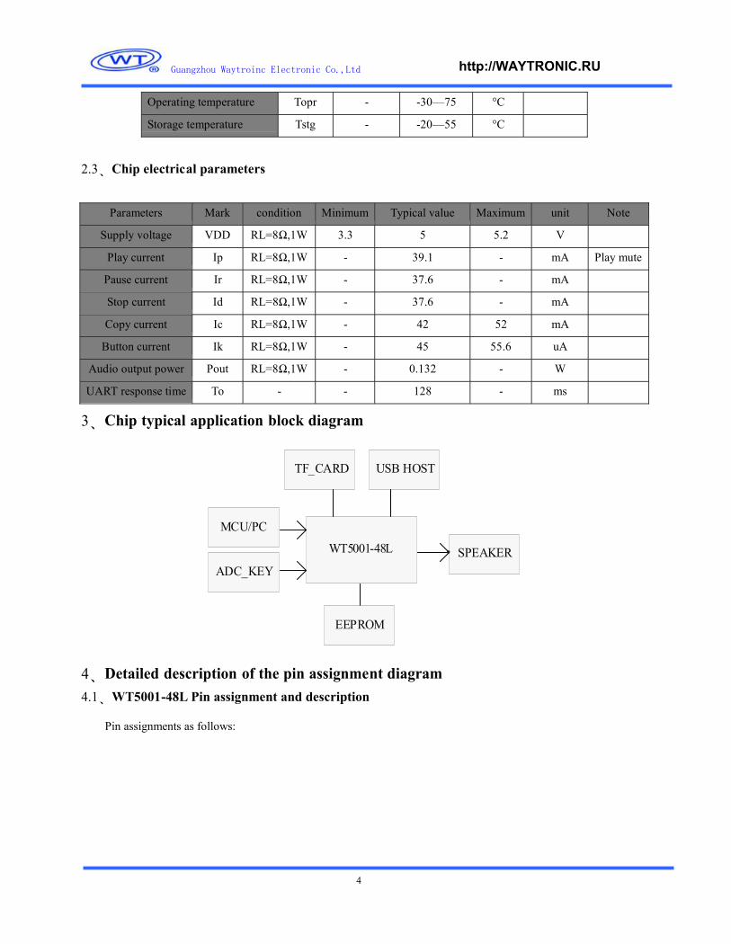
2.3、Chip electrical parameters
Parameters Mark condition Minimum Typical value Maximum unit Note
Supply voltage VDD RL=8Ω,1W 3.3 5 5.2 V
Play current Ip RL=8Ω,1W - 39.1 - mA Play mute
Pause current Ir RL=8Ω,1W - 37.6 - mA
Stop current Id RL=8Ω,1W - 37.6 - mA
Copy current Ic RL=8Ω,1W - 42 52 mA
Button current Ik RL=8Ω,1W - 45 55.6 uA
Audio output power Pout RL=8Ω,1W - 0.132 - W
UART response time To - - 128 - ms
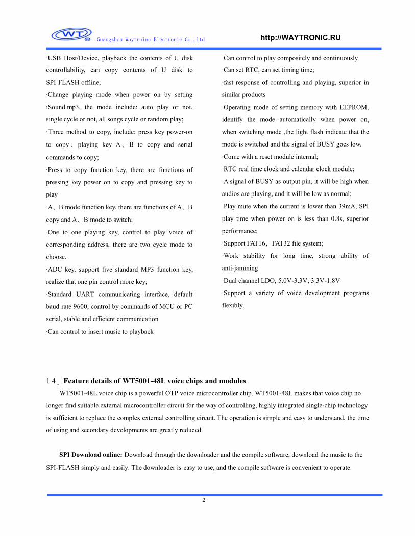
3、Chip typical application block diagram
TF_CARD USB HOST
MCU/PC
ADC_KEY
WT5001-48L SPEAKER
EEPROM
4、Detailed description of the pin assignment diagram4.1、WT5001-48L Pin assignment and description
Pin assignments as follows:

Guangzhou Waytroinc Electronic Co.,Ltd http://WAYTRONIC.RU
5
13 14 15 16 17 18 19 20 21 22 23 24
48 47 46 45 44 43 42 41 40 39 38 37
VDD
18V
SSV
DD50
VDD
33_L
DOA
DC_K
EY/D
ATA
3CA
RD_I
NS/
DA
TA4
DAT
A21
DAT
A22
DAT
A7
DAT
A6
VM
IDA
VDD3
3
XTE
STRX
D/D
ATA
9TX
D/D
ATA
8D
ATA
5EX
T_SC
L/DA
TA2
EXT_
SDL/
DATA
1D
ATA
0CA
RD_C
MD
CRA
D_D
AT
CARD
_CLK
XRE
SET
VOT
P
1 VDD33C2 VDD333 VDD184 SPI_CLK/DATA105 SPI_MOSI/DATA116 SPI_MISO/DATA12
DATA13 36
DATA14 35
DATA15 34DATA16 33
DATA17 32
DATA18 317 DP8 DM9 XI32K10 XO32K11 PLL_CP12 PLL_CI
WT5001-48L DATA19 30
DATA20 29HPVDD 28
LHPOUT 27
HPVSS 26
RHPOUT 25
Detailed description of pins:NUM NAME ATTR DESCRIPTION NOTE
1 VDD33C PWR Power switch output,3.3V power supply to external devices
2 VDD33 PWR PAD 3.3V power pin
3 VDD18 PWR 1.8Vpower supply in core
4 DATA10 IO function 1: GPIO[10];
function 2: SPI_ CLK.
Default function 2
5 DATA11 IO function 1: GPIO[11];
function 2: SPI_ MOSI.
Default function 2
6 DATA12 IO function 1: GPIO[12];
function 2: SPI MISO.
Default function 2
7 DP IO USB DP differential line
8 DM IO USB DM differential line
9 XI32K I 32.768K crystal oscillator input
10 XO32K O 32.768K crystal oscillator output
11 PLL_CP ANA PLL capacity pin, connect 2nF capacity to GND
12 PLL_C1 ANA PLL capacity pin, connect 2nF capacity to GND
13 VDD18_LDO PWR 1.8Vpower supply in core
14 VSS GND Package GND
15 VDD50 PWR LDO total power supply, minimum can not be lower than 3.3V
16 VDD33_LDO PWR LDO 3.3V output, connect to3.3V on the external
17 DATA3 IO function 1: GPIO[3];
function 2:ADC_KEY(standard MP3key)
Default function 2

Guangzhou Waytroinc Electronic Co.,Ltd http://WAYTRONIC.RU
6
18 DATA4 IO Function 1: GPIO[4];
Function 2:CARD_INS(SD card detecting pin)
Default function 2
19 DATA21 IO Function 1: GPIO[21];
Function 2:A mode key;
Default function 2
20 DATA22 IO Function 1:GPIO[22];
Function 2:Press to copy function keys;
Default function 2
21 DATA7 IO GPIO[7];
22 DATA6 IO GPIO[6];
23 VMID ANA Decoupling capacitor connecting pin
24 AVDD33 PWR DAC analog power supply pin
25 RHPOUT ANA Headphone right channel output
26 HPVSS GND DAC high power GND
27 LHPOUT ANA Headphone left channel output
28 HPVDD PWR DAC high power supply,3.3V
29 DATA20 IO Function 1: GPIO[20];
Function 2:B mode key;
Default function 2
30 DATA19 IO Function 1: GPIO[19];
Function 2:One to one function key,corresponding to the
address of the fourth song;
Default function 2
31 DATA18 IO Function 1: GPIO[18];
Function 2:One to one function key,corresponding to the
address of the third song;
Default function 2
32 DATA17 IO Function 1: GPIO[17];
Function 2:One to one function key,corresponding to the
address of the second song;
Default function 2
33 DATA16 IO Function 1: GPIO[16];
Function 2:One to one function key,corresponding to the
address of the first song;
Default function 2
34 DATA15 IO Function 1: GPIO[15];
Function 2:BUSY indicate outout;
Default function 2
35 DATA14 IO Function 1: GPIO[14];
Function 2:One to one function key,switch cycle mode;
Default function 2
36 DATA13 IO Function 1: GPIO[13],24mA drive;
37 VOTP PWR OTP programming voltage,6.5Vinput,vacant when actual
application

Guangzhou Waytroinc Electronic Co.,Ltd http://WAYTRONIC.RU
7
38 X_RESET_ I External reset pin
39 CARD_CLK IO SD/MMC/MSPRO clock bus
40 CARD_DAT IO SD/MMC/MSPRO data bus
41 CARD_CMD IO SD/MMC/MSPRO command bus
42 DATA0 IO Function 1: GPIO[0];
Function 2:Clock timer wake-up signal output, output 1
second high;
Default function 2
43 DATA1 IO Function 1: GPIO[1];
Function 2:EXT_SDL (EEPROM data bus);
Default function 2
44 DATA2 IO Function 1: GPIO[2];
Function 2:EXT_SCL (EEPROM clock bus);
Default function 2
45 DATA5 IO Function 1: GPIO[5];
Function 2:Reset down into debug mode;
46 DATA8 IO Function 1: GPIO[8];
Function 2: Serial port TXD.
Default function 2
47 DATA9 IO Function 1: GPIO[9];
Function 2: Serial port RXD.
Default function 2
48 X_TEST_MODE I Equal 1 then enter to test mode ; equal 0 then enter functional
mode
4.2、WT5001M01-16P Pin assignment and descriptionPin assignments as follows:
1 RESET2 AL3 ROUT4 LOUT5 SPI_DI6 SPI_DO7 SPI_CLK8 GND
VDD50 16
BUSY 15
VCC33 14
ADC_KEY 13
DATA22 12
RXD 11
TXD 10SPI_CEN 9
Detailed description of pin:
WT5001M01-16P
NUM NAME ATTR DESCRIPTION NOTE
1 RESET I External reset
2 AL ANA ADC audio output Can be connect to active speaker
3 ROUT ANA PWM audio output Can be connect to 1W8Ωspeaker

Guangzhou Waytroinc Electronic Co.,Ltd http://WAYTRONIC.RU
8
2 273 264 255 246 237 228 219 20
10 1911 1812 1713 1614 15
DATA16 +5V-USBNC GNDDATA17 DPDATA18 DMDATA19 DATA14NC NCRESET VDD50AL BUSYROUT VCC33LOUT ADC_KEYSPI_DI DATA22SPI_DO RXDSPI_CLK TXDGND SPI_CEN
4 LOUT ANA PWM audio output Can be connect to 1W8Ωspeaker
5 SPI_DI IO SPI main output minor input data bus SPI download port
6 SPI_DO IO SPI main input minor output data bus SPI download port
7 SPI_CLK IO SPI clock bus SPI download port
8 GND GND GND
9 SPI_CEN IO SPI chip select bus SPI download port
10 TXD IO UART send bus
11 RXD IO UART receive bus
12 DATA22 Press to copy function keys
13 ADC_KEY IO ADC standard MP3 function key
14 VCC33 PWR LDO 3.3V output
15 BUSY IO Indication output when the module is busy
16 VDD50 PWR Power supply port,DC5V
4.3、WT5001M02-28P Pin assignment and descriptionPin assignments as follows:
1 28
Detailed description of pin:
WT5001M02-28P
NUM NAME ATTR DESCRIPTION NOTE
1 DATA16 IO One to one function key,corresponding to the
address of the first song;
2 NC Connect to TF socket shell
3 DATA17 IO One to one function key,corresponding to the
address of the second song;
4 DATA18 IO One to one function key,corresponding to the
address of the third song;
5 DATA19 IO One to one function key,corresponding to the

Guangzhou Waytroinc Electronic Co.,Ltd http://WAYTRONIC.RU
9
address of the fourth song;
6 NC Connect to TF socket shell
7 RESET I External reset
8 AL ANA ADC audio output Can be connect to active speaker
9 ROUT ANA PWM audio output Can be connect to 1W8Ωspeaker
10 LOUT ANA PWM audio output Can be connect to 1W8Ωspeaker
11 SPI_DI IO SPI main output minor input data bus SPI download port
12 SPI_DO IO SPI main input minor output data bus SPI download port
13 SPI_CLK IO SPI clock bus SPI download port
14 GND GND GND
15 SPI_CEN IO SPI chip select bus SPI download port
16 TXD IO UART send bus
17 RXD IO UART receive bus
18 DATA22 IO Press to copy function keys
19 ADC_KEY IO ADC standard MP3 function key
20 VCC33 PWR LDO 3.3V output
21 BUSY IO Indication output when the module is busy
22 VDD50 PWR Power supply port,DC5V
23 NC Connect to TF socket shell
24 DATA14 IO One to one function key ,switch cycle mode
25 D- IO USB DP differential line
26 D+ IO USB DM differential line
27 GND GND U disk socket shell
28 +5V_USB PWR U disk power supply port
4.4、WT5001M03-28P Pin assignment and description
Pin assignments as follows:

Guangzhou Waytroinc Electronic Co.,Ltd http://WAYTRONIC.RU
10
2 273 264 255 246 237 228 219 20
10 1911 1812 1713 1614 15
CARD_INS +5V-USBCARD_CLK GNDCARD_DAT DPCARD_CMD DMVCC33 EXT_SCLGND EXT_SDLRESET VDD50AL BUSYROUT VCC33LOUT ADC_KEYSPI_DI DATA22SPI_DO RXDSPI_CLK TXDGND SPI_CEN
1 28
Detailed description of pin:
WT5001M03-28P
NUM NAME ATTR DESCRIPTION 备注
1 CARD_INS IO (SD card detect pin)
2 CARD_CLK IO SD/MMC/MSPRO clock bus
3 CARD_DAT IO SD/MMC/MSPRO data bus
4 CARD_CMD IO SD/MMC/MSPRO command bus
5 VCC33 PWR SD card power supply
6 GND GND SD card GND
7 RESET I External reset
8 AL ANA ADC audio output Can be connect to active speaker
9 ROUT ANA PWM audio output Can be connect to 1W8Ωspeaker
10 LOUT ANA PWM audio output Can be connect to 1W8Ωspeaker
11 SPI_DI IO SPI main output minor input data bus SPI download port
12 SPI_DO IO SPI main input minor output data bus SPI download port
13 SPI_CLK IO SPI clock bus SPI download port
14 GND GND GND
15 SPI_CEN IO SPI chip select bus SPI download port
16 TXD IO UART send bus
17 RXD IO UART receive bus
18 DATA22 IO Press to copy function keys
19 ADC_KEY IO ADC standard MP3 functional key
20 VCC33 PWR LDO 3.3V output
21 BUSY IO Indication output when the module is busy
22 VDD50 PWR Power supply port,DC5V
23 EXT_SDL IO EEPROM data bus;

Guangzhou Waytroinc Electronic Co.,Ltd http://WAYTRONIC.RU
11
24 EXT_SCL IO EEPROM data bus;
25 D- IO USB DP differential line
26 D+ IO USB DM differential line
27 GND GND U disk GND
28 +5V_USB PWR U disk power supply port
5、Detailed description of the functional operation5.1、BUSY indicate output
There is an output signal BUSY, when there are audios playing, the output will be high, and be low as normal.
5.2、Function detail of ADC standard key mode
Function and operationKey operation
Play\PauseShort pressPLAY
Long press Stop
Select next songShort press
Fast forward (when playing)NEXT
Long press
Select next songShort press
Fast reverse (when playing)LAST
Long press
Volume increaseShort press
Volume increase rapidlyVOL+
Long press
Short press Volume decreaseVOL-
Long press Volume decrease rapidly
5.3、Function setting description5.3.1、Setting method
There is an iSound.mp3 document in SD card .Copy all mp3 files in SD card to SPI flash to operate, while all the
configurations in iSound.mp3 file is updated to the SPI flash, the specific storing location as below.
Note: you can open iSound.mp3 file on the computer by "Notebook” or "WordPad", modify the setting parameters
inside. Please don’t mistake the uppercase and lowercase of the"ISound.mp3" file name.
5.3.2、Function detail
StartP: 00、No play power-on, 01、Auto play power-on;

Guangzhou Waytroinc Electronic Co.,Ltd http://WAYTRONIC.RU
12
Cycle: 00、No cycle,01、Single cycle, 02、All songs cycle,03、Random play
5.3.3、ISound.mp3 file storing location
ISound.mp3 files must put at the final storing address of SD card or U disk, that is the final to deposit to the SD
card or U disk ( the final of index sequence).
5.4、SPI FLASH copy function5.4.1、Method of mass production
Edit the project file by PC software, programmed into the SPI FLASH directly.
5.4.2、Copy method of SD card or U disk
First edit iSound.mp3 file, copy it to SD card or U disk, and then copy the voice file you want to put in SD card or
U disk in order, finish it; through three operating methods copy to SPI-FLASH, (default the original mode unchanged if
there isn’t iSound.mp3 file)
1、 Press the key for 5S when power on, the red light BUSY flash that it will start to copy then release the key, red
light BUSY flash until the copy ends.
2、Long press the A key and B key for 5S, the red light BUSY flash that it will start to copy then release the key,
red light BUSY flash until the copy ends.
3、The MCU send serial commands to achieve copying, BUSY light indicates as the first method, when finish the
copy, the serial port output an instruction, the specific instructions see agreement below.
Note: The sequence of the music files copied to the SPI-FLASH is the order of the file address stored in SD card
or U disk, which is index order of the file in SD card or U disk.
5.4.3、The order of music file stored in SD card:
As the order of file address in SD card is the order of index, that is, who is the first to copy, whose memory
address is at first. And the order of WT5001-48L playing music in SD card is in accordance with the order of the
memory address in SD card, so be clearly that the order of the file in SD card which WT5001-48L specify to playback
with, the first that you must store the file in SD card in order as planed. The following is the method to store files in SD
card:
Build a file folder on your computer , to place the music files which will be stored in SD card, and make them in
good order (if you want to know the files order clearly , you can add to each music file name with "0001-9999", such as
0001 the Motherland mp3, 0002 love story. mp3, rank in the order of the file, Select all the music files which will be
stored in SD card, such as CTRL + A ", and then right-click the first file, select "sent to the removable storage (SD card
or U disk), so the order of music files in SD card is desired.
Note: the order of music files stored in the U disk is similar as in SD card.

Guangzhou Waytroinc Electronic Co.,Ltd http://WAYTRONIC.RU
13
5.5、Description of specific function:5.5.1、Press to copy function keys
The normal function of the key (DATA22) is: short press, is for the next one, when play the final song, back to the
first song ,and the playing mode is single cycle mode; long press, is copy function when power-on , first press the key
and hold before power-on, after 5S power on ,BUSY indicator flashes (said to enter the copy), release the button until
the BUSY indicator stop flashing and darken, copy success.
5.5.2、One to one function key
When DATA14 is high, DATA16 \ DATA17 \ DATA18 \ DATA19 correspond to 1, 2, 3, 4 pieces of voice, low
pulse trigger and play once then stop.
When DATA14 is low, DATA16 \ DATA17 \ DATA18 \ DATA19 correspond to 1, 2, 3, 4 pieces of voice, when
low to maintain ,the playing mode is single cycle, when jump to high it will finish the current song then stop.
5.5.3、A、B mode function key
A、B keys are set two different operating modes: short press A key (DATA21) to select last song, long press A key
(DATA21) for 3S to set to A mode; short press B key (DATA20) to select next song, long press B key (DATA20) for
3S to set to B mode, the key is active low. When there is an EEPROM, it can remember the operating mode, identify
the mode automatically when power on. As switching the mode, the light flashes indicate switching success and BUSY
goes low.
Model A: auto play current song (Memory) each time when power-on, play it once and stop.
Mode B: play the next one (Memory) each time when power-on, play it once and stop; when play the finial one
power-on, then start to play the first one when power-on next time.
Note: when using A, B mode, there must be the EEPROM to memory power-down.
5.6、Description of storage5.6.1、Stored format
The storage of SD card and U disk supports FAT16, FAT32 file system.
5.6.2、Memory power down
Memory store to the EEPROM when power down that is a standard function, memory power-down include
volume value, the current playing song number and the setting of A, B mode referred below; when there isn’t external
EEPROM, it will be no memory processing when power down ,but can not affect other functions;

Guangzhou Waytroinc Electronic Co.,Ltd http://WAYTRONIC.RU
14
5.7、Process audio filesSupport MP3, WMA, WAV format audio files. (It will need different models to support WMA and WAV)
If the MP3 files store in SPI-FALSH, it can be lower bit rate MP3 format files.
6、Serial communication control protocol6.1、Protocol command format
Start code Length Opcode Parameter End code
0X7E See below See below See below 0X7E
Note: The "length" refers to the length + opcode + the length of the parameter, as follows 12.2.2 the command that
specifying the file in SD card to playback, of which the length is 4 bytes.
6.2、write instruction6.2.1、Format of code returned from writing instruction
Opcode
XX
Note: After perform each writing command, return to one byte operation code corresponded to the command.
6.2.2、Specify the files in SD card to playback
This command can specify the files in SD card to playback, it doesn’t effect by the order of files stored.
Start code Length Command High bit of songs Low bit of songs End code
7E 04 A0 00 01 7E
6.2.3、Specify the files in SPI Flash to playback
This command can specify to the files operate only in SPI Flash.
Start code Length Command High bit of songs Low bit of songs End code
7E 04 A1 00 01 7E
6.2.4、Specify the files in U disk to playback
This command can specify the files to operate only in U disk.
Start code Length Command High bit of songs Low bit of songs End code

Guangzhou Waytroinc Electronic Co.,Ltd http://WAYTRONIC.RU
15
7E 04 A2 00 01 7E
6.2.5、PauseStart code Length Command End code
7E 02 A3 7E
Sending the command first time to pause the music, send the data again, continue to play music from the
suspension.
6.2.6、StopStart code Length Command End code
7E 02 A4 7E
Sending the command to stop the current song.
6.2.7、Next songStart code Length Command End code
7E 02 A5 7E
The instruction trigger to play the next song, when playing the first song, sending the command can trigger to play
the final music.
6.2.8、Last songStart code Length Command End code
7E 02 A6 7E
The instruction trigger to play the last song, when playing the last song, sending the command can trigger to play
the first song.
6.2.9、Volume control
The volume levels are total of 32, from 00 to 31, which 00 is mute, 31 is maximum volume.
Start code Length Command Volume level End code
7E 03 A7 1F 7E
The command in example is to send a maximum volume 31, this instruction can adjust the volume in real time,
and the volume can be in memory power-down.
6.2.10、Combine to play
This command can specify certain files to play continuously in the current directory

Guangzhou Waytroinc Electronic Co.,Ltd http://WAYTRONIC.RU
16
Start code Length Command High bit of songs Low bit of songs End code
7E 04 A8 00 01 7E
The combination of playing is sending 10 groups or less music combination code to the WT5001-48L
continuously, WT5001-48L play the music according to the sequence of code received. Different from sending name to
control directly is that the next code can not a music not interrupt the playing until finish the current song , receive the
command to do FIFO processing. Example : WT5001 continuously receive "7E 04 A8 00 08 7E ","7E 04 A8 00 06 7E
", "7E A8 04 00 07 7E "," 7E A8 04 00 04 7E "," 7E 04 A8 00 03 7E ","7E 04 A8 00 02 7E " six sets of data,
WT2801-S specify to play SD files named" 0008.mp3 "," 0006.mp3 "," 0007.mp3 "," 0004.mp3 ","0003.mp3 ","
0002.mp3 "6 audio files in order.
Note:
Before the combination of playing, if you want to play other mode of files stored, you must first send the specified
storage mode playing command, the track in instructions fill in the first one of the combination of playing, and then
send the tracks behind in the instructions, to realize combine to play.
B, Combination of playing only in the non-cyclic mode, is invalid in the single cycle mode or all songs cycle mode,;
C, The continuous combination is maximum 10 groups. During playback, if there is a new command it can be
interrupted, and implement the new command.
6.2.11、Set playing modeStart code Length Command Parameter End code
00:single and no cycle (default)
01:single and cycle
02:all songs cycle7E 03 A9
03:random play
7E
Note: The instruction is to modify the playing mode when power on, when power down, the mode will return to
the mode which is configured in iSOUND.mp3 file. Using the instructions, it is proposal that MCU set the mode as
initializing the module to realize performing as setting each time.
6.2.12、Instruction of copy the content from SD card to SPI FLASHStart code Length Command End code
7E 03 AA 00 7E
Note: it will return "AA" immediately after receive the instruction, while the indicator flashes, if copy successfully
it will return "AA 00", if not, it will return "AA 01"; the indicator stop flashing when the copy finished.

Guangzhou Waytroinc Electronic Co.,Ltd http://WAYTRONIC.RU
17
6.2.13、Instruction of copy the content from U disk to SPI FLASHStart code Length Command End code
7E 03 AB 00 7E
Note: it will return "AB" immediately after receive the instruction, while the indicator flashes, if copy successfully
it will return "AB 00", if not, it will return "AB 01"; the indicator stop flashing when the copy finished.
6.2.14、Instruction of insertionStart code Length Command High bit of songs Low bit of songs End code
7E 04 AC 00 01 7E
Note: When receive the instruction, the current song will pause, and then execute this command to playback the
specified song, when finish playing, it will play the original song which is pause. This instruction only can be
implemented in SPI- FLASH.
6.3、Instructions of setting clock6.3.1、Set data information
Start code Length Opcode Year(2bytes) Month(1byte) Day (1byte) End code
7E 05 B1 2011 05 08 7E
Note: The year, month, day are hexadecimal code, such as the data of 2011 is 07 DB.
6.3.2、Set time information
Start code Length Opcode Hour(1byte) Minute (1byte) Second(1byte) End code
7E 06 B2 20 07 08 7E
Note: The hour, minute, second are shown as hexadecimal code.
6.3.3、Set waking up time information
Start code Length Opcode Hour (1byte) Minute (1byte) Second (1byte) End code
7E 05 B3 0A 05 08 7E

Guangzhou Waytroinc Electronic Co.,Ltd http://WAYTRONIC.RU
18
Note: after executing this instruction, the clock of IC will record a time, when it’s time to the setting time, DATA0
of IC will output one second pulse signal; after MCU of the controlling side detects the pulse signal from INT, sent the
inquiry instruction through the serial port to read the current time, then it will know to perform what procedures this
time.
6.3.4、Set information of time period
Start code Length Opcode Hour (1byte) Minute (1byte) Hour (1byte) Minute(1byte) End code
7E 06 B4 06 05 06 08 7E
Note: The first two bytes represent the starting time, the latter two represent the cut-off time.
If there is MCU, this function can be implemented through the microcontroller, so we do not consider to
performing any function.
6.3.5、Clear the information of timing
Start code Length Opcode End code
7E 02 B5 7E
6.3.6、Clear the information of time period
Start code Length Command End code
7E 02 B6 7E
6.4、The command of reading operation
6.4.1、Read the current volume valueStart code Length Command End code
7E 02 C1 7E
The format returned:Opcode Return value
0XC1 Volume value
6.4.2、Read the current playing stateStart code Length Command End code

Guangzhou Waytroinc Electronic Co.,Ltd http://WAYTRONIC.RU
19
7E 02 C2 7E
The format returned:Opcode Return value
0XC201:Play 02 Stop;
03:Pause
6.4.3、Read the total number of files in SPI FlashStart code Length Command End code
7E 02 C3 7E
The format returned:Opcode Return value
0XC3 Total number of files
6.4.4、Read the total number of files in SD cardStart code Length Command End code
7E 02 C4 7E
The format returned:Opcode Return value
0XC4 Total number of files
6.4.5、Read the total number of files in U diskStart code Length Command End code
7E 02 C5 7E
The format returned:Opcode Return value
0XC5 Total number of files
6.4.6、Read the current audio filenameStart code Length Command End code
7E 02 C6 7E
The format returned:Opcode High bit of files number Low bit of files number
0XC6 XX XX

Guangzhou Waytroinc Electronic Co.,Ltd http://WAYTRONIC.RU
20
6.4.7、Read the current data information
Start code Length Opcode End code
7E 02 D1 7E
The format returned:
Opcode Year (2bytes) Month (1bytes) Day (1bytes)
0XD1 XX XX XX
6.4.8、Read the current time information
Start code Length Opcode End code
7E 02 D2 7E
The format returned:
Opcode Hour (1bytes) Minute(1bytes) Second(1bytes)
0XD2 XX XX XX
7、Example of application circuit7.1、WT5001M01-16P Minimum application circuit diagram
S1 R8
LS?
A?1 RESET2 AL3 ROUT
VDD50 16
BUSY 15
VCC33 14
VDD50 VOL+
S2
VOL-
200K 1%
R9
150K 1%
R104 LOUT ADC_KEY 13 ADC_KEY S3
SPEAKER5 SPI_DI6 SPI_DO7 SPI_CLK8 GND
DATA22 12
RXD 11
TXD 10
SPI_CEN 9
FOLDER1
S4
FOLDER2
100K 1%
R15
51K1%
WT5001M01-16P S5
FOLDER
R16
15K1%

Guangzhou Waytroinc Electronic Co.,Ltd http://WAYTRONIC.RU
21
7.2、WT5001M02-28P Minimum application circuit diagram
LS?
SPEAKER
2 NC3 DATA17
5 NC6 DATA19
8 AL9 ROUT10 LOUT11 SPI_DI12 SPI_DO13 SPI_CLK14 GND
GND 27
DP 26
NC 24
DATA14 23
BUSY 21
VCC33 20
ADC_KEY 19
DATA22 18
RXD 17
TXD 16
SPI_CEN 15
VDD50
ADC_KEY
VOL+
VOL-
FOLDER1
S4
FOLDER2
S5
FOLDER3
200K 1%
R9
150K 1%
R10
100K 1%
R15
51K1%
R16
15K1%
WT5001M02-28P
7.3、WT5001M03-28P Minimum application circuit diagram
LS?
SPEAKER
2 CARD_CLK3 CARD_DAT
5 VCC336 GND
8 AL9 ROUT10 LOUT11 SPI_DI12 SPI_DO13 SPI_CLK14 GND
WT5001M03-28P
GND 27
DP 26
EXT_SCL 24
EXT_SDL 23
BUSY 21
VCC33 20
ADC_KEY 19
DATA22 18
RXD 17
TXD 16
SPI_CEN 15
VDD50
ADC_KEY
VOL+
VOL-
FOLDER1
S4
FOLDER2
S5
FOLDER3
200K 1%
R9
150K 1%
R10
100K 1%
R15
51K1%
R16
15K1%
Recommended