The Motion Interactive Medical Exercise
Robot (MIMER) Project
Teaching Movement through Technology
First Semester Report – Fall 2013
-- First Semester Report --
Completed By:
Salem Al-Aqeel
John Allison
Trevor Pier
Jay Vickers
Lucas Wadman
Daniel White
Prepared to partially fulfill the
Requirements for ECE401
Department of Electrical and Computer Engineering
Colorado State University
Fort Collins, Colorado 80523
Project Advisors: Sudeep Pasricha, Anthony Maciejewski
Approved by: Sudeep Pasricha and Anthony Maciejewski
The MIMER Project – Colorado State University
2 | P a g e
Abstract
The Mirror Neuron System (MNS) in every human being is crucial for development. This
system allows people to take in auditory or ocular cues to make a decision and to complete a
task. Sometimes this system is not fully developed, but this can be alleviated through repetitive
movements and practice using the MNS. An underdeveloped system is usually found in stroke
victims and has also been linked to autism [1].
One way to exercise and develop this system is to practice picking up a phone. The phone
will ring and the client will answer it. Another way is for a nurse to raise their hand above their
head repetitively while the client watches, then for the patient to reproduce this motion.
“Exercising” the MNS not only helps with physical motor development, but with cognitive
processes as well. Mirror neuron units are thought to be involved with the ability to imitate and
learn from other’s actions and understand intentions from body language [1].
There are devices that use motion and visual cues for therapy, rehabilitation, and
development of the MNS. Games for stroke patients that use motion controls to develop motor
skills have been created. Robots have been developed by other institutions that have functionality
of mirroring such as the Bandit from USC and the NAO by Aldebaran Robotics. Physical
therapy is widely used for children with underdeveloped MNS, but since this requires one on one
attention it can be expensive. If some of this time could be spent with Motion Interactive
Medical Exercise Robot (MIMER), it could cut costs and resources used. MIMER will allow a
child to practice these motions to develop their MNS to help with their development.
This project’s goal is to produce MIMER, which mimics and encourages movement of
underdeveloped children. The main purpose of this device is to provide therapy for the clients to
gain basic motor and neuronal function.
The MIMER Project – Colorado State University
3 | P a g e
Table of Contents
Abstract ........................................................................................................................................... 2
List of Figures ................................................................................................................................. 6
List of Tables .................................................................................................................................. 6
Chapter 1 - Introduction .................................................................................................................. 7
Introduction and Background ...................................................................................................... 7
Objectives and Constraints .......................................................................................................... 7
Design Summary ......................................................................................................................... 8
Chapter 2 – Sensing Equipment .................................................................................................... 12
Why Use The Kinect? ............................................................................................................... 12
Kinect Objectives and Constraints ............................................................................................ 13
Testing and Accomplishments with the Kinect......................................................................... 14
Ethical Considerations for the Kinect ....................................................................................... 14
Chapter 3 – Microcontroller Decisions ......................................................................................... 15
Selecting a Microcontroller ....................................................................................................... 15
Constraints ................................................................................................................................. 15
Testing ....................................................................................................................................... 16
Accomplishments ...................................................................................................................... 16
Ethical Considerations............................................................................................................... 16
Chapter 4 – Coding Algorithms .................................................................................................... 16
Mirroring Shoulders and Arms ................................................................................................. 16
Selection and Constraints of the Mirroring Algorithm .......................................................... 16
Testing and Accomplishments of the Mirroring Code .......................................................... 17
Selecting a Hand Tracking Algorithm ...................................................................................... 18
Selection of Algorithm .......................................................................................................... 18
Constraints with Hand Tracking ............................................................................................ 18
Ethical Considerations............................................................................................................... 18
Chapter 5 – Motors and Structural Components........................................................................... 18
Design Concepts ........................................................................................................................ 18
Testing ....................................................................................................................................... 20

The MIMER Project – Colorado State University
4 | P a g e
Evaluation Methods................................................................................................................... 22
At Risk Items and Mitigation Plan ............................................................................................ 22
Implementing reliable motors ................................................................................................ 23
Implementing light weight hands .......................................................................................... 23
Desirable range of motion ..................................................................................................... 23
Failure Modes and Effects Analysis.......................................................................................... 24
Design for Reliability, Maintenance, and Safety ...................................................................... 25
Chapter 6 – Power Circuit Design ................................................................................................ 25
Advantages of Chosen Power Circuit ....................................................................................... 25
Objectives and Constraints ........................................................................................................ 26
Potential Issues and Solutions ................................................................................................... 26
Test Considerations ................................................................................................................... 27
Progress So Far.......................................................................................................................... 27
Ethical Considerations............................................................................................................... 28
Conclusion .................................................................................................................................... 28
Appendix A – Abbreviations ........................................................................................................ 29
Appendix B – Budget Breakdown ................................................................................................ 30
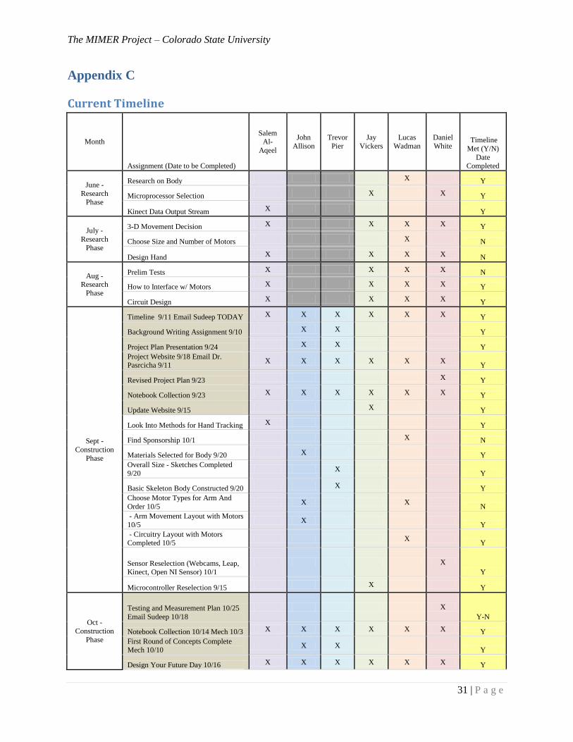
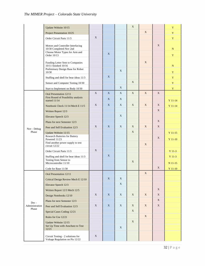
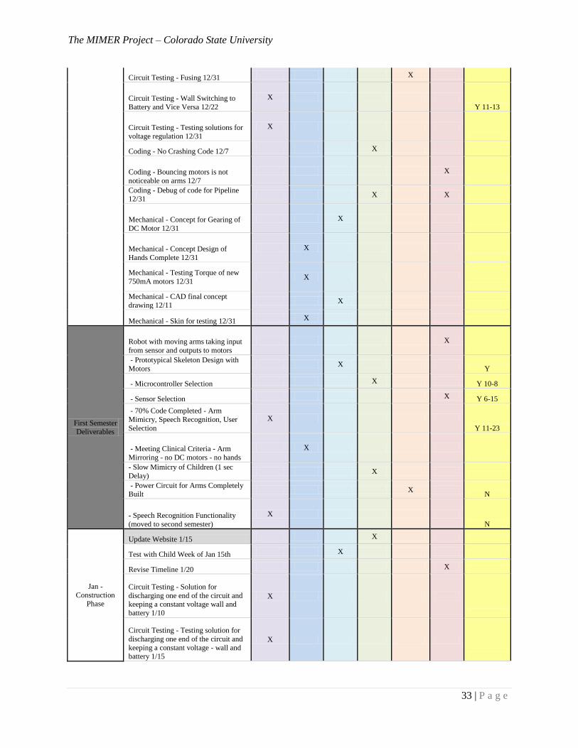
Appendix C ................................................................................................................................... 31
Current Timeline ....................................................................................................................... 31
October 28th
, 2013 Timeline ..................................................................................................... 35
October 8th
, 2013 Timeline ....................................................................................................... 38
September 27th
, 2013 Timeline ................................................................................................. 41
Appendix D – Circuit Layout ....................................................................................................... 45
Stacked Architecture ................................................................................................................. 45
Parallel Architecture .................................................................................................................. 45
Appendix E – Funding Documents ............................................................................................... 46
Appendix F – Thank You Letter ................................................................................................... 48
Appendix G – Mechanical Tests and Calculations and Future Hand Designs ............................. 49
Motor Testing ............................................................................................................................ 49
Torque Calculations .................................................................................................................. 51
Motor Current Calculations ....................................................................................................... 52

The MIMER Project – Colorado State University
5 | P a g e
Future Hand Design .................................................................................................................. 54
Acknowledgements ....................................................................................................................... 56
Works Cited .................................................................................................................................. 56
The MIMER Project – Colorado State University
6 | P a g e
List of Figures
Figure 1: Basic Final Concept......................................................................................................... 9
Figure 2: Selection of Servo Motors ............................................................................................... 9
Figure 3: Lynxmotion Components .............................................................................................. 10
Figure 4: Kinect for Windows [25] ............................................................................................... 10
Figure 5: Raspberry Pi Controller [26] ......................................................................................... 11
Figure 6: Cytron 12V DC Motor [26] ........................................................................................... 11
Figure 7: Concept of Wheeled Housing [28] ................................................................................ 11
Figure 8: Kinect Innards [4] .......................................................................................................... 12
Figure 9: Joint Tracking for Xbox Kinect [6] ............................................................................... 13
Figure 10: Range of Kinect [5] ..................................................................................................... 14
Figure 11: Coordinates .................................................................................................................. 17
Figure 12: Design Mockups of MIMER ....................................................................................... 19
Figure 13: Motor Testing Rig ....................................................................................................... 20
Figure 14: 2nd Motor Testing Rig ................................................................................................ 20
Figure 15: Circuit - Stacked Architecture ..................................................................................... 45
Figure 16: Parallel Architecture .................................................................................................... 45
Figure 18: Motor Test Configurations .......................................................................................... 49
Figure 19: Calculations without Hand and Wrist ......................................................................... 51
Figure 20: Arm with Hand and Wrist ........................................................................................... 52
Figure 21: Futaba Current Draw Calculations .............................................................................. 53
Figure 22: Finger Concepts ........................................................................................................... 54
Figure 23: Finger with Tensioning Rod ........................................................................................ 55
Figure 24: Finger without Tensioning Rod ................................................................................... 55
Figure 25: Potential Hand Design ................................................................................................. 55
List of Tables
Table 1: Constraints (Priority Levels On a 1-10 Scale – 10 Being the Most Important) ............... 8
Table 2: Motor Selection .............................................................................................................. 19
Table 3: Structure Materials.......................................................................................................... 21
Table 4: Mechanical Objectives.................................................................................................... 22
Table 5: Mechanical Constraints .................................................................................................. 22
Table 6: Failure Modes and Effects Analysis ............................................................................... 24
Table 7: Voltage Requirements .................................................................................................... 26
Table 8: Power Circuit Constraints ............................................................................................... 26
Table 9: Budget Breakdown ......................................................................................................... 30
Table 10: Motor Testing Results and Observations ...................................................................... 49
Table 11: Torque Calculations with Wrist and Hand ................................................................... 52
Table 12: Current Calculations ..................................................................................................... 53
The MIMER Project – Colorado State University
7 | P a g e
Chapter 1 - Introduction
Introduction and Background
The main purpose of this device is to provide therapy for the clients to gain basic motor
and neuronal function through use of this device. The Anschutz medical center at the University
of Colorado Denver has determined this need from observing positive results from a child with
Autism using a similar device. It has been determined that the medical center could use such a
device to help with underdeveloped young clients that need help with motor and neuronal
development.
There is some biological theory behind why a robot that mimics movements would help
with development. Studies have been done that determined the existence of Mirror Neuron
System in humans, which are functional neuronal units that connect the observation of a
movement with its execution. In other words, these units allow someone to observe a person
doing a motion such as raising their hand, and are able to replicate that movement just by seeing
it happen. “Exercising” these units not only helps with physical motor development, but with
cognitive processes as well. The Mirror Neuron System is thought to be involved with the ability
to imitate and learn from other’s actions and understand intentions from body language.
The problem that this solves is that it helps develop these skills in children while saving
time and money with a simple automated device. The need for this device was determined by the
Anschutz Medical Center by observing positive results with children using a similar device and a
basic understanding of the biological theory of why it should work. The stake that our customer
holds (Michael Melonis of Anschutz) is a more effective way to help children hit important
developmental milestones. The stake of the end users, the children, is receiving useful therapy to
help with their development, which carries through later in their lives.
Objectives and Constraints
It has been determined that in order to meet the needs of the sponsors and their clients we
need to meet certain constraints. This project should minimize cost to build the primary robot
and consider construction costs to minimize reproduction cost in the future when compared to
competitors in the market. If size and weight can be reduced it will not only save on cost but
will also make the robot more portable for ease of use. The size, price and weight of motors to
operate arms would further be reduced by a smaller lighter robot. The goal is to make arms light
enough to allow operation by small radio control (RC) servo motors. Another area of focus is
appearance. MIMER should appear life like with realistic animal or human movement, short
response time to movement and should be aesthetically pleasing by most children users. Finally,
a robot would only be useful if humans were not necessary for operation except possibly to turn
it on and off during a session with little need for repair. In summary, the primary goals are to
build a robot that is inexpensive, small, light, fast, realistic, attractive and autonomous. These
goals can be achieved by setting measureable objectives. Current constraints with assigned
priority levels on a 1-10 scale are listed in Table 1: Constraints (Priority Levels On a 1-10 Scale
– 10 Being the Most Important).
The MIMER Project – Colorado State University
8 | P a g e
Table 1: Constraints (Priority Levels On a 1-10 Scale – 10 Being the Most Important)
Objective Priority Method of
Measure
Objective
Direction
Target
Cost 8 USD Minimize < $ 1,500
Size 9 Height (in) Minimize < 24 in.
React. Speed 10 Time (ms) Minimize < 1,500 ms
Movement 10 DOF Maximize ≥ 4 DOF/arm
Weight 8 lbs Minimize < 1 lb/per arm
Autonomy 8 # Interventions Minimize < 2/session
Attractive 10 Time (min) Maximize Holds attention of 50%
of children >10mins
These constraints represent what the final product needs to accomplish to be determined
successful. There are other aspects that have been decided to be included in the final product,
these are additional objectives that add to the product’s functionality, but have not been
determined to be constraints:
Adding mimicking hands with one wrist motor and three finger motors
Final product to be self-contained, with rechargeable battery and all processing done on
two Raspberry Pi controllers
Voice recognition program to accept voice commands and encourage movement through
sound output
Additional scripted features of the robot to encourage movement (ex. The child says, “do
this” and MIMER does a motion the child should imitate)
Design Summary
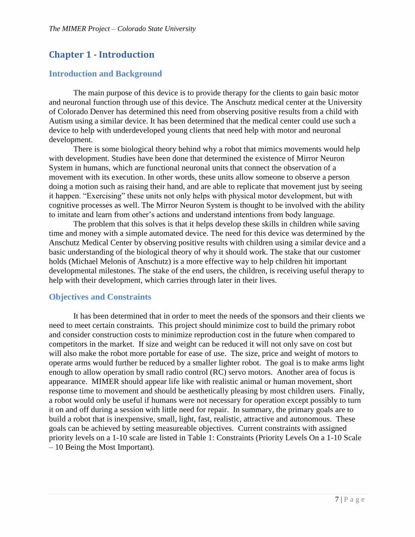
Most aspects of the design of the project have been decided. In summary, the mimicking
robot will sit on top of a small cart or shelf with wheels that will hold the electronics and put the
robot at a height that would be easy to interact with. The robot itself will be constructed of servo
motors and specialized brackets and will have a kid-friendly outward appearance. The processing
will be done with two Raspberry Pi controllers (one for each arm). The Microsoft Kinect will be
used to track motions of the user. The device will have an onboard battery, and processing will
be done on a laptop before moving the processing to the Raspberry Pi’s. The cart will also have
some movement capacity; there will be two DC motors to pan the device left and right to follow
the user, and one to adjust distance for optimal operation. The main components of the design are
showcased below in Error! Reference source not found..
The MIMER Project – Colorado State University
9 | P a g e
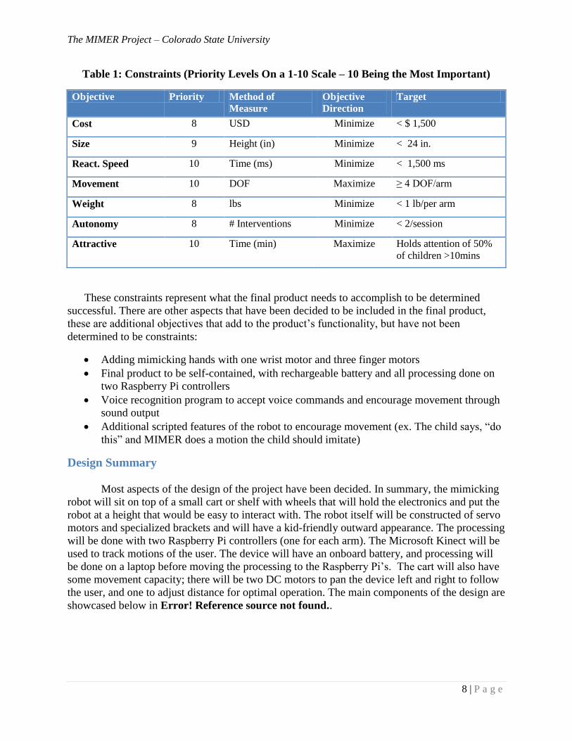
Servo Motors: These will provide motion capability for the arms. Testing has been done
with many servos. The baseline servo that is being used is the HS-422; a full arm has been
constructed with 4 of these motors (two in the shoulder, two in the elbow). While the basic
motion of the arm was successful, it could be optimized. Based on the performance of these
motors, it has been decided that smaller motors should be used in the elbows to reduce the
moment arm (HS-85 Figure 2: Selection of Servo Motors), and higher torque motors should be
used in the shoulders (HS-645 Figure 2: Selection of Servo Motors). Finger and wrist movement
will be handled by feather weight servos (HS-55 Figure 2: Selection of Servo Motors).
Kinect
BodyKi
Battery
Motor controlled
wheels
Power circuit and
electronics
Raspberry Pi
Wireless connection
to laptop
Robot Body
HS-85 [19] HS-645 [20] HS-55 [21]
Figure 2: Selection of Servo Motors
Figure 1: Basic Final Concept
The MIMER Project – Colorado State University
10 | P a g e
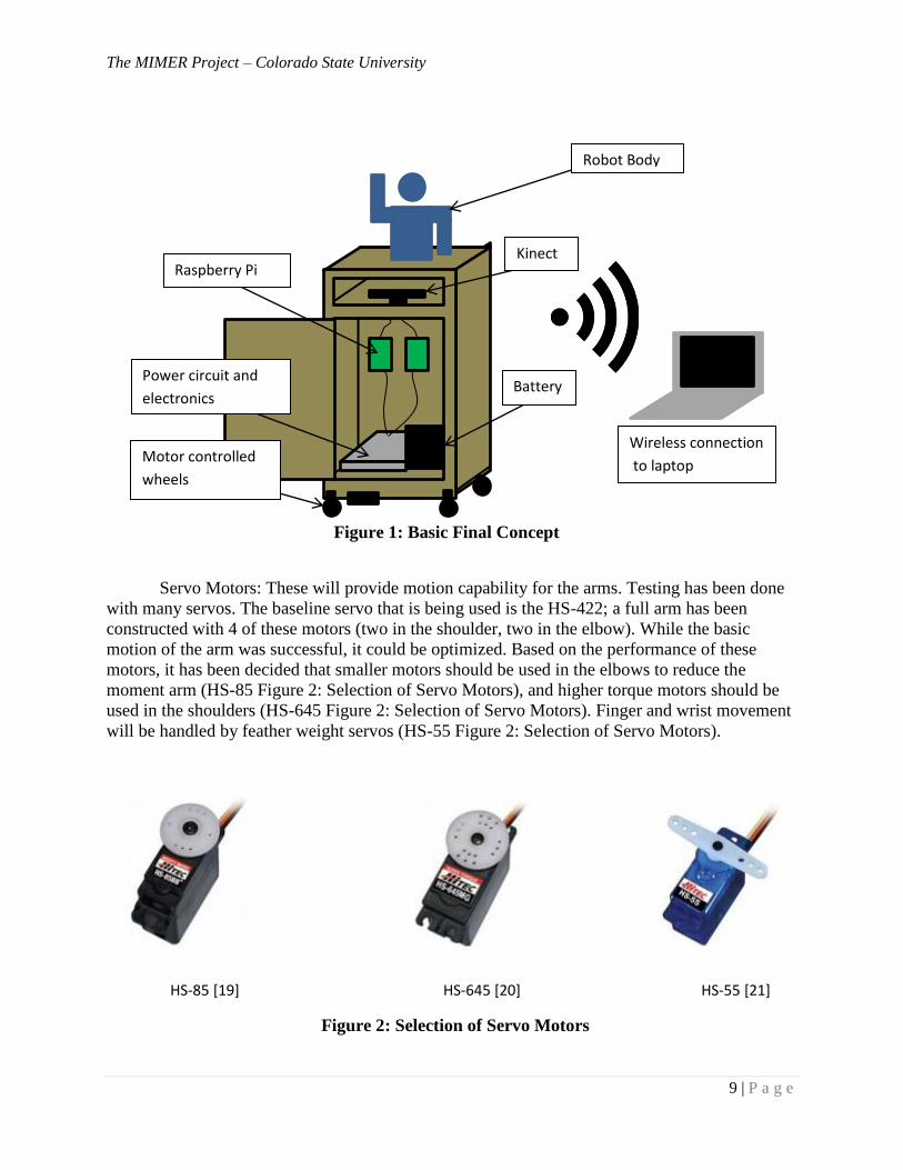
Bracket System: This is used to incorporate the motors into a skeletal system to achieve
the desired movement. Lynxmotion is a system of brackets that are standardized to fit different
sizes of servos and connect them together as shown in Figure 3: Lynxmotion Components. The
components are light weight and have been successful in testing the assembled arm.
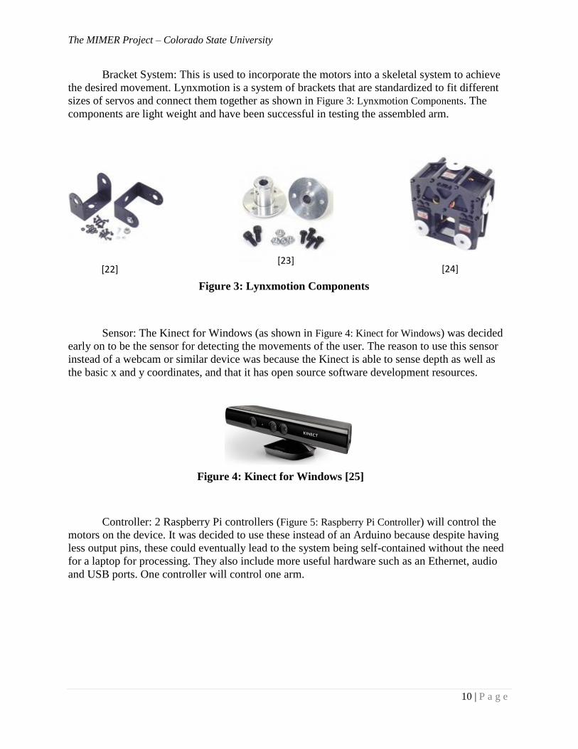
Sensor: The Kinect for Windows (as shown in Figure 4: Kinect for Windows) was decided
early on to be the sensor for detecting the movements of the user. The reason to use this sensor
instead of a webcam or similar device was because the Kinect is able to sense depth as well as
the basic x and y coordinates, and that it has open source software development resources.
Controller: 2 Raspberry Pi controllers (Figure 5: Raspberry Pi Controller) will control the
motors on the device. It was decided to use these instead of an Arduino because despite having
less output pins, these could eventually lead to the system being self-contained without the need
for a laptop for processing. They also include more useful hardware such as an Ethernet, audio
and USB ports. One controller will control one arm.
Figure 3: Lynxmotion Components
Figure 4: Kinect for Windows [25]
[22] [23]
[24]
The MIMER Project – Colorado State University
11 | P a g e
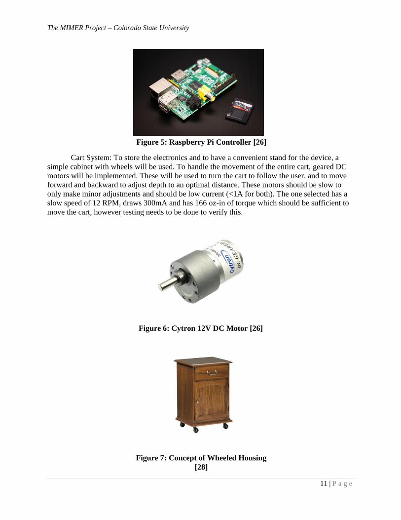
Cart System: To store the electronics and to have a convenient stand for the device, a
simple cabinet with wheels will be used. To handle the movement of the entire cart, geared DC
motors will be implemented. These will be used to turn the cart to follow the user, and to move
forward and backward to adjust depth to an optimal distance. These motors should be slow to
only make minor adjustments and should be low current (<1A for both). The one selected has a
slow speed of 12 RPM, draws 300mA and has 166 oz-in of torque which should be sufficient to
move the cart, however testing needs to be done to verify this.
Figure 6: Cytron 12V DC Motor [26]
Figure 5: Raspberry Pi Controller [26]
Figure 7: Concept of Wheeled Housing
[28]
The MIMER Project – Colorado State University
12 | P a g e
Chapter 2 – Sensing Equipment
Why Use The Kinect?
The Microsoft Kinect has been chosen as a sensing device for our project because it
meets our Electrical and Mechanical needs. “The Microsoft Kinect is currently the most
advanced motion sensing input device, and is easiest to use that is available to consumers”; it
enables users to interact and control the application or game without the need to touch an input
device. With a familiar user interface by using gestures and voice commands the application can
be controlled. Using an object recognizing approach, the Kinect can capture 3D body joint
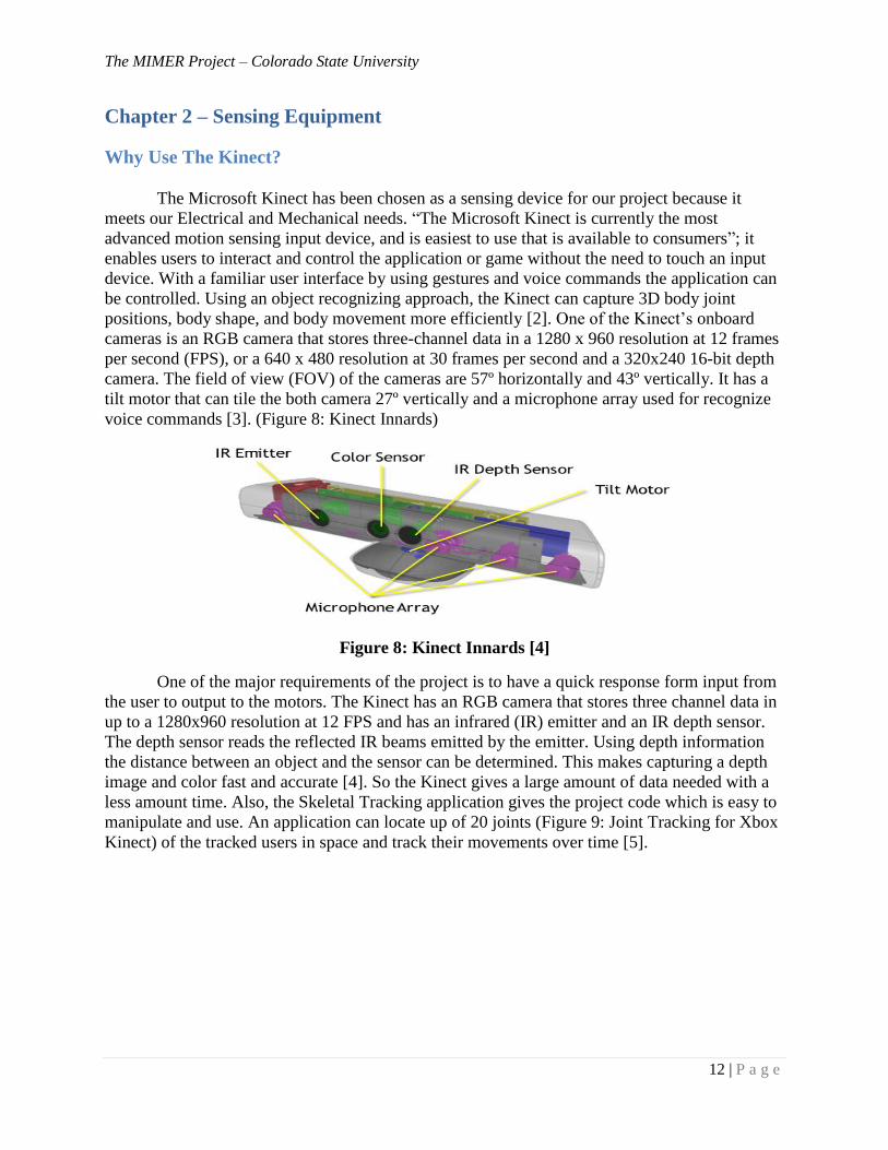
positions, body shape, and body movement more efficiently [2]. One of the Kinect’s onboard
cameras is an RGB camera that stores three-channel data in a 1280 x 960 resolution at 12 frames
per second (FPS), or a 640 x 480 resolution at 30 frames per second and a 320x240 16-bit depth
camera. The field of view (FOV) of the cameras are 57º horizontally and 43º vertically. It has a
tilt motor that can tile the both camera 27º vertically and a microphone array used for recognize
voice commands [3]. (Figure 8: Kinect Innards)
Figure 8: Kinect Innards [4]
One of the major requirements of the project is to have a quick response form input from
the user to output to the motors. The Kinect has an RGB camera that stores three channel data in
up to a 1280x960 resolution at 12 FPS and has an infrared (IR) emitter and an IR depth sensor.
The depth sensor reads the reflected IR beams emitted by the emitter. Using depth information
the distance between an object and the sensor can be determined. This makes capturing a depth
image and color fast and accurate [4]. So the Kinect gives a large amount of data needed with a
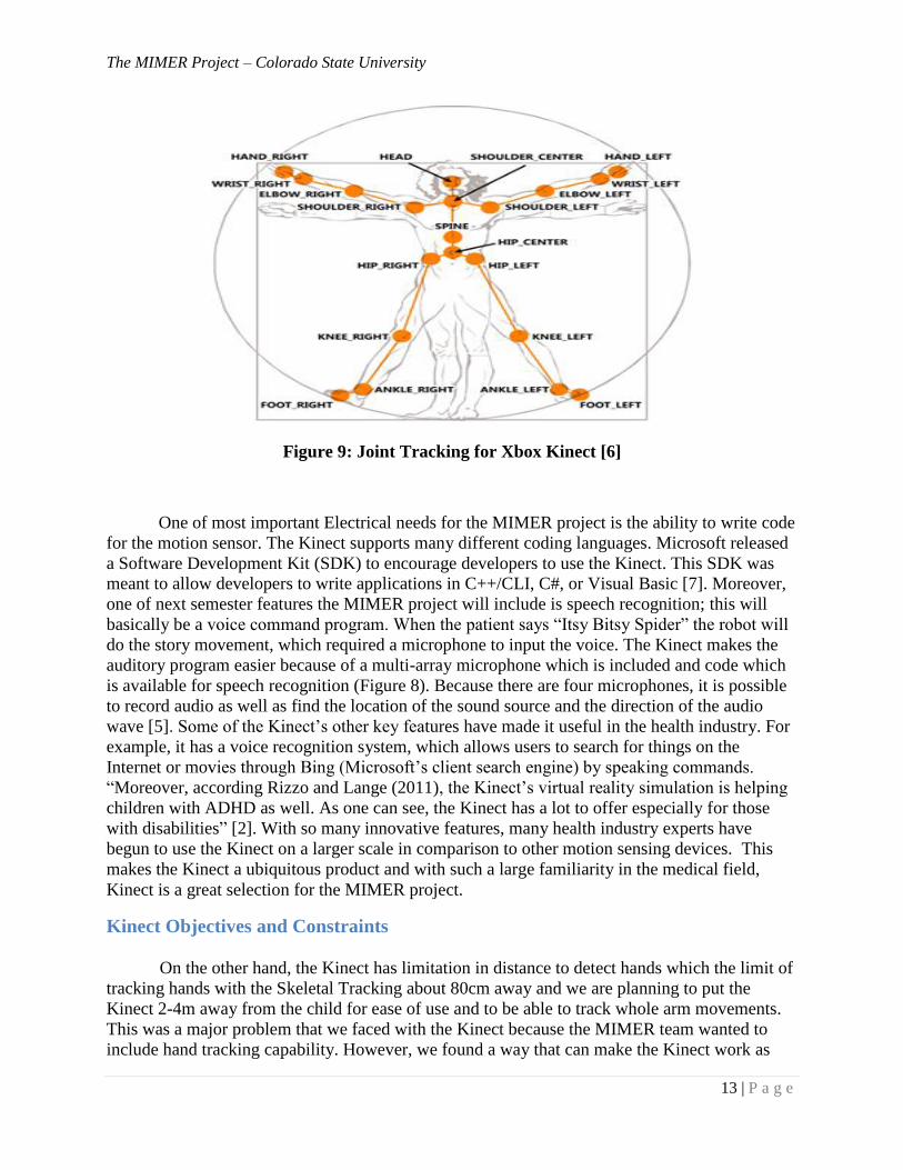
less amount time. Also, the Skeletal Tracking application gives the project code which is easy to
manipulate and use. An application can locate up of 20 joints (Figure 9: Joint Tracking for Xbox
Kinect) of the tracked users in space and track their movements over time [5].
The MIMER Project – Colorado State University
13 | P a g e
Figure 9: Joint Tracking for Xbox Kinect [6]
One of most important Electrical needs for the MIMER project is the ability to write code
for the motion sensor. The Kinect supports many different coding languages. Microsoft released
a Software Development Kit (SDK) to encourage developers to use the Kinect. This SDK was
meant to allow developers to write applications in C++/CLI, C#, or Visual Basic [7]. Moreover,
one of next semester features the MIMER project will include is speech recognition; this will
basically be a voice command program. When the patient says “Itsy Bitsy Spider” the robot will
do the story movement, which required a microphone to input the voice. The Kinect makes the
auditory program easier because of a multi-array microphone which is included and code which
is available for speech recognition (Figure 8). Because there are four microphones, it is possible
to record audio as well as find the location of the sound source and the direction of the audio
wave [5]. Some of the Kinect’s other key features have made it useful in the health industry. For
example, it has a voice recognition system, which allows users to search for things on the
Internet or movies through Bing (Microsoft’s client search engine) by speaking commands.
“Moreover, according Rizzo and Lange (2011), the Kinect’s virtual reality simulation is helping
children with ADHD as well. As one can see, the Kinect has a lot to offer especially for those
with disabilities” [2]. With so many innovative features, many health industry experts have
begun to use the Kinect on a larger scale in comparison to other motion sensing devices. This
makes the Kinect a ubiquitous product and with such a large familiarity in the medical field,
Kinect is a great selection for the MIMER project.
Kinect Objectives and Constraints
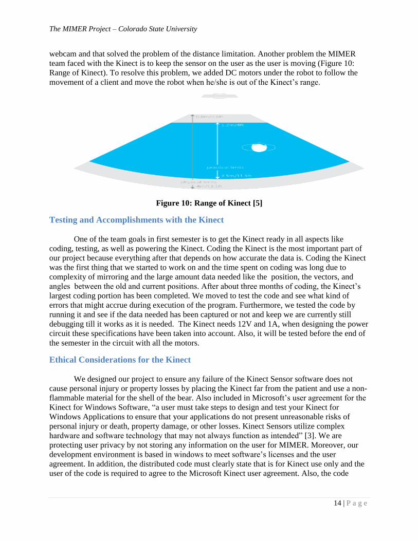
On the other hand, the Kinect has limitation in distance to detect hands which the limit of
tracking hands with the Skeletal Tracking about 80cm away and we are planning to put the
Kinect 2-4m away from the child for ease of use and to be able to track whole arm movements.
This was a major problem that we faced with the Kinect because the MIMER team wanted to
include hand tracking capability. However, we found a way that can make the Kinect work as
The MIMER Project – Colorado State University
14 | P a g e
webcam and that solved the problem of the distance limitation. Another problem the MIMER
team faced with the Kinect is to keep the sensor on the user as the user is moving (Figure 10:
Range of Kinect). To resolve this problem, we added DC motors under the robot to follow the
movement of a client and move the robot when he/she is out of the Kinect’s range.
Figure 10: Range of Kinect [5]
Testing and Accomplishments with the Kinect
One of the team goals in first semester is to get the Kinect ready in all aspects like
coding, testing, as well as powering the Kinect. Coding the Kinect is the most important part of
our project because everything after that depends on how accurate the data is. Coding the Kinect
was the first thing that we started to work on and the time spent on coding was long due to
complexity of mirroring and the large amount data needed like the position, the vectors, and
angles between the old and current positions. After about three months of coding, the Kinect’s
largest coding portion has been completed. We moved to test the code and see what kind of
errors that might accrue during execution of the program. Furthermore, we tested the code by
running it and see if the data needed has been captured or not and keep we are currently still
debugging till it works as it is needed. The Kinect needs 12V and 1A, when designing the power
circuit these specifications have been taken into account. Also, it will be tested before the end of
the semester in the circuit with all the motors.
Ethical Considerations for the Kinect
We designed our project to ensure any failure of the Kinect Sensor software does not
cause personal injury or property losses by placing the Kinect far from the patient and use a non-
flammable material for the shell of the bear. Also included in Microsoft’s user agreement for the
Kinect for Windows Software, “a user must take steps to design and test your Kinect for
Windows Applications to ensure that your applications do not present unreasonable risks of
personal injury or death, property damage, or other losses. Kinect Sensors utilize complex
hardware and software technology that may not always function as intended” [3]. We are
protecting user privacy by not storing any information on the user for MIMER. Moreover, our
development environment is based in windows to meet software’s licenses and the user
agreement. In addition, the distributed code must clearly state that is for Kinect use only and the
user of the code is required to agree to the Microsoft Kinect user agreement. Also, the code
The MIMER Project – Colorado State University
15 | P a g e
should be an open source not for commercial software hosting services and a valid code
copyright notice should be displayed to protect our code.
Chapter 3 – Microcontroller Decisions
Selecting a Microcontroller
In order to best select a microcontroller, the MIMER team had to review the important
characteristics for this project as a whole. As a team we decided that it is an essential feature that
the MIMER project should be able to fully operate as a self-contained system. In order to
provide adequate clinical services, the system needs to operate with no external wiring to distract
patients. The system also has to be able to process depth data and send outputs to the motors with
a maximum response time of 1 second. It is important that a potential microcontroller selection
be able to exhibit the aforementioned characteristics while also providing an easy to use interface
Although the microcontroller must reflect the design philosophy of the project as a
whole, there are also a number of technical specifications that needed to be met. In order to
correctly mirror movement read in from the Kinect, this system will have to feed data through
multiple complex algorithms at a speed of 30 frames per second. The sheer amount data
processing to be done indicates that any microcontroller must have a relatively fast clock speed;
we limited our search to nothing less than 500MHz. Initially our design philosophy called for the
MIMER project to be battery powered. This design constraint indicates that any processing must
be done with low power usage. Continuing with the theme of a self-contained design, we also
needed our controller to have enough on board memory to store compilers and code so that all
processing and computation can be done within the robot itself.
Constraints
In the end we felt that the Raspberry Pi microcontroller was the most suitable choice to
fulfill the technical specifications and match the design philosophy of the MIMER project. The
one major drawback with the selection of the Raspberry Pi as the main processing unit is the
limited number of General-Purpose Input/Output (GPIO) pins on the device. The robot will be
driven by 16-20 motors and the Raspberry Pi only has 17 pins available for control. This
problem is simply solved by using two Raspberry Pi’s in the circuit; this decision also provides
us with extra processing power that can help alleviate some of the load on one controller. The
Raspberry Pi can run on a Debian based Linux operating system, this has greatly helped in
reducing the learning curve for the team members well versed in manipulating Linux systems.
The operating system also allows for the use of diverse code compilers, some of the competing
microcontrollers would have required our algorithms be composed in the C++ programming
language. This is important because all of the Kinect libraries for skeletal tracking are written in
C#. Due to the fact that we are using a Debian based operating system on the Raspberry Pi, we
were able to find a C# compiler that can run directly on the microcontroller. This compiler
allows us to use some of the built in skeletal recognition features within the Kinect, alleviating
some of the computational pressure from any custom skeletal tracking algorithms. Overall we
feel that the Raspberry Pi is the best choice on the market to meet our high processing design
constraints.
The MIMER Project – Colorado State University
16 | P a g e
Testing
Microcontroller testing has mainly consisted of motor control verification. Currently
preliminary motor control testing has been simulated in a closed environment. The test setup
included one small servo motor connected to the General-Purpose Input/Output pins of a
Raspberry pi. To test the ability to control servo motors the microcontroller was executing a
custom duty cycle computation algorithm that outputs the computed duty cycle to the motor.
This test resulted in the motor rotating the correct degree amount and showing that we are able to
accurately control the angle of rotation for servo motors with the Raspberry pi. More complex
motor testing simulation has shown that the current operating system in use on the test
microcontroller is only running the control algorithm at 20MHz instead of the full 700MHz. The
team is currently testing algorithms on a more “light-weight” operating system in hopes to
achieve a higher running speed.
Accomplishments
Our main accomplishments with the microcontroller are a confident choice in a
microcontroller as well as beginning the testing phase.
Ethical Considerations
This section of the project does not contain any necessary ethical decisions or
considerations.
Chapter 4 – Coding Algorithms
Mirroring Shoulders and Arms
This section provides explanation of the mirroring the shoulders and arms portion of the
code for MIMER. All code can be requested from the group at any time.
Selection and Constraints of the Mirroring Algorithm
To select a useful algorithm the team kept in mind the constraints of the MIMER:
MIMER needs an input to output time of less than one second, and MIMER needs to be accurate
in tracking the child. The algorithm chosen is a simple algorithm that will track the child close,
but not perfectly. This will allow the child to keep the attention on MIMER, and know that
MIMER is following them. Since this algorithm is simple the computation will be fast and the
motors and the microcontroller will be able to read all the information the code from the
computer is releasing.
The first step in the mirroring code is to read in the joint locations given from the Kinect
and use those joint locations to find the angles MIMER needs to move to. The first angle to find
is the angle from the hip, to shoulder, to elbow. To find this angle, use Equation 1, shown below.
The second shoulder angle to be found is the rotation angle. This angle is found from Equation 2,
shown below. The elbow angles are more difficult than the shoulder angles because the plane of
reference is moving. The vector between the shoulder and elbow is found as well as the vector
The MIMER Project – Colorado State University
17 | P a g e
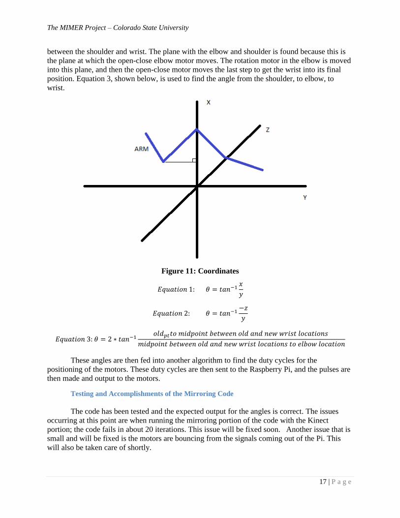
between the shoulder and wrist. The plane with the elbow and shoulder is found because this is
the plane at which the open-close elbow motor moves. The rotation motor in the elbow is moved
into this plane, and then the open-close motor moves the last step to get the wrist into its final
position. Equation 3, shown below, is used to find the angle from the shoulder, to elbow, to
wrist.
Figure 11: Coordinates
These angles are then fed into another algorithm to find the duty cycles for the
positioning of the motors. These duty cycles are then sent to the Raspberry Pi, and the pulses are
then made and output to the motors.
Testing and Accomplishments of the Mirroring Code
The code has been tested and the expected output for the angles is correct. The issues
occurring at this point are when running the mirroring portion of the code with the Kinect
portion; the code fails in about 20 iterations. This issue will be fixed soon. Another issue that is
small and will be fixed is the motors are bouncing from the signals coming out of the Pi. This
will also be taken care of shortly.
The MIMER Project – Colorado State University
18 | P a g e
Selecting a Hand Tracking Algorithm
Selection of Algorithm
Selection of the hand tracking algorithm has not been finalized as of yet. The
consideration for hand tracking are using the webcam functionalities of the Kinect or using a
webcam separately. This will allow us to use a finger tracking algorithm to see which fingers are
up. There are some code samples to finger tracking from online resources that track the midpoint
of the palm and use this to find the distances between the middle of the palm and tips of the
fingers to see if the fingers are up or down. The team is still looking into this algorithm.
Constraints with Hand Tracking
One of the major constraints to hand tracking is the number of calculations for duty
cycles that need to be done. To simplify this, the team has decided to only look to see if the
finger is up or down, not anywhere in between. This will speed up the code to allow faster
response time.
Ethical Considerations
The ethical considerations that are being thought about are to keep the child safe and to
not distribute any code that is not written by any member of the team. MIMER runs off some
code from Microsoft; which we are allowed to use for this project, but the code cannot be
distributed. The code from Codeplex.com is also written under a similar Microsoft License.
Chapter 5 – Motors and Structural Components
Design Concepts
Any robot project must begin with the determination of degrees of freedom in the joints.
Human anatomy is complicated and is very difficult to replicate. However, with some creative
analysis one can model the movements with minimal degradation of realism. Firstly, the
MIMER team constructed a physical and CAD (Computer Aided Design) model to verify that
pivots in the arm joints give realistic movement compared to a human arm. Both types of
models were constructed to gain confidence in motor number and placement.
The MIMER Project – Colorado State University
19 | P a g e
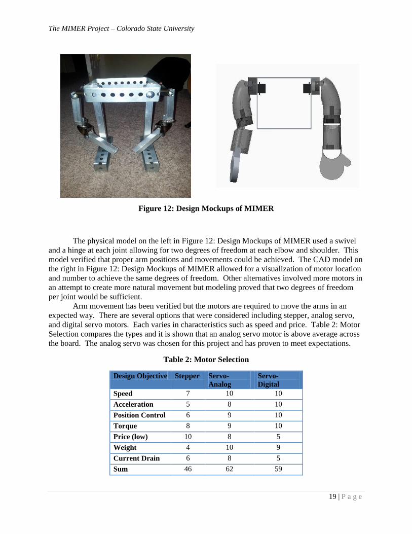
Figure 12: Design Mockups of MIMER
The physical model on the left in Figure 12: Design Mockups of MIMER used a swivel
and a hinge at each joint allowing for two degrees of freedom at each elbow and shoulder. This
model verified that proper arm positions and movements could be achieved. The CAD model on
the right in Figure 12: Design Mockups of MIMER allowed for a visualization of motor location
and number to achieve the same degrees of freedom. Other alternatives involved more motors in
an attempt to create more natural movement but modeling proved that two degrees of freedom
per joint would be sufficient.
Arm movement has been verified but the motors are required to move the arms in an
expected way. There are several options that were considered including stepper, analog servo,
and digital servo motors. Each varies in characteristics such as speed and price. Table 2: Motor
Selection compares the types and it is shown that an analog servo motor is above average across
the board. The analog servo was chosen for this project and has proven to meet expectations.
Table 2: Motor Selection
Design Objective Stepper Servo-
Analog
Servo-
Digital
Speed 7 10 10
Acceleration 5 8 10
Position Control 6 9 10
Torque 8 9 10
Price (low) 10 8 5
Weight 4 10 9
Current Drain 6 8 5
Sum 46 62 59

The MIMER Project – Colorado State University
20 | P a g e
Testing
It was determined that the motors would need to be tested to verify they meet design
criteria such as speed, torque, and safety. A test apparatus was built using simple household
materials, an Arduino Uno microcontroller, and an arm from the prototypical physical model that
weighed 0.4lbs shown below in Figure 13: Motor Testing Rig.
Figure 13: Motor Testing Rig
The servo motor, hidden behind the arm in Figure 13: Motor Testing Rig, represents one
shoulder swivel. This view point would be similar to a human turned sideways. Full weight and
torque of the arm is handled by the one motor at the shoulder and should be a conservative
estimate of future arm designs that should be lighter and shorter than this one. If a motor can
move this arm with accuracy and speed then it should be a suitable motor for this project. Five
different motors have been tested with this rig and the one shown in Figure 14: 2nd Motor
Testing Rig.
Figure 14: 2nd Motor Testing Rig
Motors were tested at different speeds to determine how quickly the weight could be
accelerated into the next programmed position. Lower torque motors struggled with this task;
however, the larger motors could accelerate the arm with little delay. The largest motor
considered is still not powerful enough to cause injury to humans by hitting or pinching although
it is powerful enough to serve its purpose. Two motor models broke during testing and three
others were very successful. Potential hazards due to overheating were examined. Once a motor
breaks or is held in one position for an extended period of time, it begins to heat up the external
casing that may be in contact with other flammable materials. Throughout testing, temperature is
monitored and will be mitigated with fuses and robust motor selection. A minimum of three

The MIMER Project – Colorado State University
21 | P a g e
spare motors will be available to the customer with instructions on replacement in case one
should wear out the gears or fail unexpectedly.
Testing provided information on what specifications to look for in future purchases and
which brands are more reliable. This information was vital due to the large portion of budget
that will be spent on motors. Details on motor testing can be found in Appendix G. Future tests
will include lighter smaller high torque motors in the elbows to reduce current draw, torque and
wear on the shoulder motors. In addition, tests will be required once hands and fingers with
associated motors are implemented due to extra weight and length added to the arm.
Figure 14: 2nd Motor Testing Rig showed the second motor rig that used two shoulder
and two elbow servos with brackets and tubing holding them together to form an arm. It was
determined that purchasing these Lynxmotion lightweight brackets over fabricated parts made
for easy assembly at a low cost that is easy to replicate as described in Table 3: Structure
Materials.
Table 3: Structure Materials
Design Objective Metal-
Fab
Plastic-
Fab
Lynxmotion
Durability 9 8 10
Time to build 5 6 10
Ease of
Replication
6 8 10
Price (low) 8 10 9
Weight 7 10 9
Sum 35 42 48
A second arm will be made after the first is a proven concept. Any sharp edges on
brackets or screw tips protruding will be covered or filed to prevent injury when customers
handle or perform maintenance on the robot. Spare hardware will be available to the customer
with the robot.
Structurally, the robot has requirements that must be upheld. Objectives and constraints
in Table 4: Mechanical Objectives and
Table 5: Mechanical Constraints summarize these requirements. Although, these
requirements were made at the start of the project, all are satisfied by the current designs and
prototypes.
The MIMER Project – Colorado State University
22 | P a g e
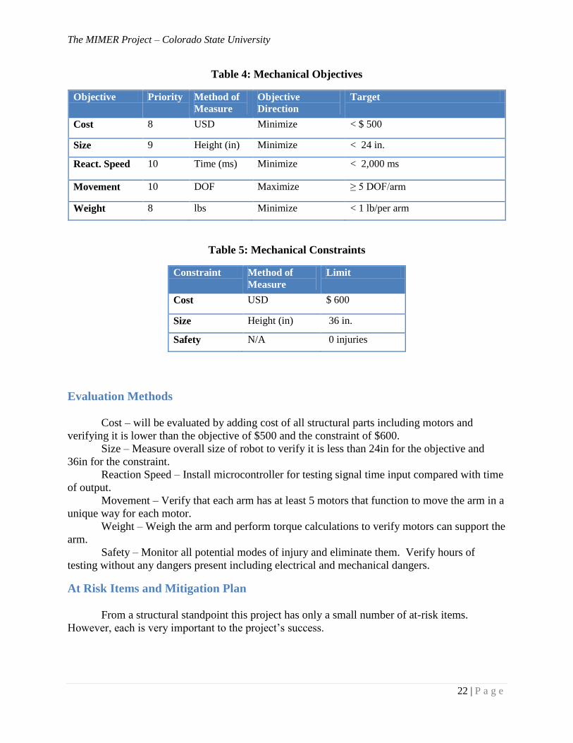
Table 4: Mechanical Objectives
Objective Priority Method of
Measure
Objective
Direction
Target
Cost 8 USD Minimize < $ 500
Size 9 Height (in) Minimize < 24 in.
React. Speed 10 Time (ms) Minimize < 2,000 ms
Movement 10 DOF Maximize ≥ 5 DOF/arm
Weight 8 lbs Minimize < 1 lb/per arm
Table 5: Mechanical Constraints
Constraint Method of
Measure
Limit
Cost USD $ 600
Size Height (in) 36 in.
Safety N/A 0 injuries
Evaluation Methods
Cost – will be evaluated by adding cost of all structural parts including motors and
verifying it is lower than the objective of $500 and the constraint of $600.
Size – Measure overall size of robot to verify it is less than 24in for the objective and
36in for the constraint.
Reaction Speed – Install microcontroller for testing signal time input compared with time
of output.
Movement – Verify that each arm has at least 5 motors that function to move the arm in a
unique way for each motor.
Weight – Weigh the arm and perform torque calculations to verify motors can support the
arm.
Safety – Monitor all potential modes of injury and eliminate them. Verify hours of
testing without any dangers present including electrical and mechanical dangers.
At Risk Items and Mitigation Plan
From a structural standpoint this project has only a small number of at-risk items.
However, each is very important to the project’s success.
The MIMER Project – Colorado State University
23 | P a g e
Implementing reliable motors
If the robot will be in the hands of doctors and clinicians in Denver, far away from the
designers, then the motors must be reliable. Motor testing has only introduced knowledge of
possible motor failures. Testing will continue to verify the motors can run for at least 100 hours
total and at least 12 hours consecutively with an expected weight attached to each model.
Motors should remain consistent in position control and speed throughout testing.
Implementing light weight hands
Hands and fingers for a small stuffed animal should be small themselves however they
need motors and associated parts to operate them which add significant weight even using the
lightest servo motors on the market. Fingers will be the furthest weight from the origin that the
shoulder motor must lift which means that even small weights become magnified torque.
Another challenge when designing hands is strength is sacrificed with decreasing weight when
using inexpensive materials. This item will be mitigated through creative engineering using
fewer fingers with hollow durable design. Motors will weigh less than 0.28oz each. Fingers will
be a focus in the coming months.
Desirable range of motion
Initially this item was not a concern. However, after constructing parts of the newest arm
with brackets, motors, and hardware it was noted that some motors are restricted from their full
180 degree range of motion. All of the many parts use more space than predicted. Once wrists
and fingers are added this issue may become more complex. Additionally, all parts must fit into
a stuffed animal or toy skin that does not have the appearance of awkward thick arms. In many
cases a human arm cannot achieve a 180 degree range and these cases will not be a problem but
the few in which they can will need to be mimicked properly by the robot. Smaller elbow
motors should help in the elbow and different brackets in the shoulder will need to be researched
or fabricated. Wrists and fingers will be dealt with in the coming months.
The MIMER Project – Colorado State University
24 | P a g e
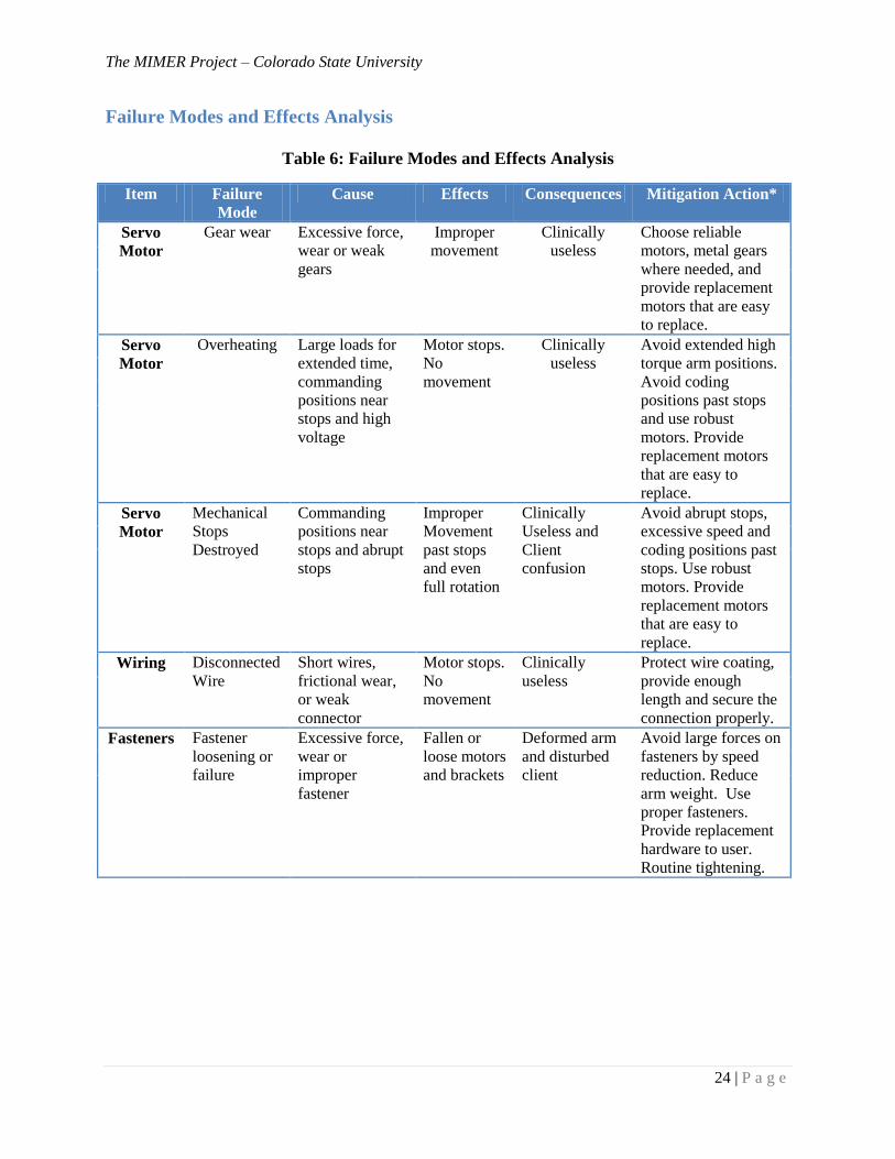
Failure Modes and Effects Analysis
Table 6: Failure Modes and Effects Analysis
Item Failure
Mode
Cause Effects Consequences Mitigation Action*
Servo
Motor
Gear wear Excessive force,
wear or weak
gears
Improper
movement
Clinically
useless
Choose reliable
motors, metal gears
where needed, and
provide replacement
motors that are easy
to replace.
Servo
Motor
Overheating Large loads for
extended time,
commanding
positions near
stops and high
voltage
Motor stops.
No
movement
Clinically
useless
Avoid extended high
torque arm positions.
Avoid coding
positions past stops
and use robust
motors. Provide
replacement motors
that are easy to
replace.
Servo
Motor
Mechanical
Stops
Destroyed
Commanding
positions near
stops and abrupt
stops
Improper
Movement
past stops
and even
full rotation
Clinically
Useless and
Client
confusion
Avoid abrupt stops,
excessive speed and
coding positions past
stops. Use robust
motors. Provide
replacement motors
that are easy to
replace.
Wiring Disconnected
Wire
Short wires,
frictional wear,
or weak
connector
Motor stops.
No
movement
Clinically
useless
Protect wire coating,
provide enough
length and secure the
connection properly.
Fasteners Fastener
loosening or
failure
Excessive force,
wear or
improper
fastener
Fallen or
loose motors
and brackets
Deformed arm
and disturbed
client
Avoid large forces on
fasteners by speed
reduction. Reduce
arm weight. Use
proper fasteners.
Provide replacement
hardware to user.
Routine tightening.
The MIMER Project – Colorado State University
25 | P a g e
Design for Reliability, Maintenance, and Safety
As mentioned, MIMER will be used by doctors and clinicians in Denver which means
that Fort Collins students will not be on location if something fails or needs replacing. Also, the
robot will be utilized by small children that can be unpredictable and prone to damage and
injury. These factors present the need for a robot that is reliable, easy to repair, and safe.
As mentioned in previous sections, rigorous testing is on-going and will cease only when
reliability and safety is maximized. Reliable motors have been identified. Structural
components are sound, easy to replace, and readily available on the Internet. Motors can be
replaced with common screwdrivers and sockets provided to the user. The robot skin will be in
sections that can be removed by snaps or zippers to allow easy access. Most electronic circuitry
will be housed in a cabinet beneath the robot to allow easy access and cooling. Robots can be
inherently safe through wiring and programming using fuses and interlocks such as over-current
or a switch that will shut the robot down when someone gets too close. Sharp edges and tips will
be filed or covered. Warning labels will be applied where needed. An operation manual will be
provided to the user that includes safety warnings and maintenance tips as well.
Dynamics of the many moving and stationary parts have created many obstacles and will
surely continue to do so. Obstacles will be overcome with further testing, brainstorming, and
calculations as they have been up to this point. The next biggest challenge will be designing and
implementing reliable light weight hands with realistic movement.
Mechanical information that can be found in Appendix G – Mechanical Tests and
Calculations include: Motor testing, Torque Calculations, Motor Current Calculations, and
Future Hand Design.
Chapter 6 – Power Circuit Design
This section covers the semester’s progress made in powering the MIMER. One design
feature of the project is the MIMER team would like MIMER to be self-contained, meaning it
operates with little to no external interfaces, e.g. power plugs. It was clear in the concept
exploration stages of the project that the design would require our team to design custom power
electronics given the unique combination of the Kinect, servo motors, and other electronic
equipment in the robot.
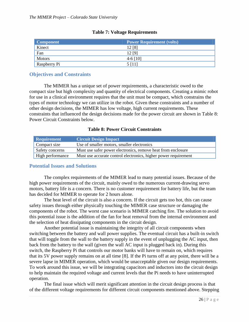
Advantages of Chosen Power Circuit
Designing custom circuitry for the MIMER allows the project flexibility in a number of
areas versus purchasing an off the shelf power solution. We have flexibility in the power delivery
to different components that have different voltage requirements, which are listed in Table 7:
Voltage Requirements below. Given components that require such a variety of power levels,
designing our own power circuit is the best option we have to accomplish a self-contained
solution in the final product.
The MIMER Project – Colorado State University
26 | P a g e
Table 7: Voltage Requirements
Component Power Requirement (volts)
Kinect 12 [8]
Fan 12 [9]
Motors 4-6 [10]
Raspberry Pi 5 [11]
Objectives and Constraints
The MIMER has a unique set of power requirements, a characteristic owed to the
compact size but high complexity and quantity of electrical components. Creating a mimic robot
for use in a clinical environment requires that the unit must be compact, which constrains the
types of motor technology we can utilize in the robot. Given these constraints and a number of
other design decisions, the MIMER has low voltage, high current requirements. These
constraints that influenced the design decisions made for the power circuit are shown in Table 8:
Power Circuit Constraints below.
Table 8: Power Circuit Constraints
Requirement Circuit Design Impact
Compact size Use of smaller motors, smaller electronics
Safety concerns Must use safer power electronics, remove heat from enclosure
High performance Must use accurate control electronics, higher power requirement
Potential Issues and Solutions
The complex requirements of the MIMER lead to many potential issues. Because of the
high power requirements of the circuit, mainly owed to the numerous current-drawing servo
motors, battery life is a concern. There is no customer requirement for battery life, but the team
has decided for MIMER to operate for 2 hours alone.
The heat level of the circuit is also a concern. If the circuit gets too hot, this can cause
safety issues through either physically touching the MIMER case structure or damaging the
components of the robot. The worst case scenario is MIMER catching fire. The solution to avoid
this potential issue is the addition of the fan for heat removal from the internal environment and
the selection of heat dissipating components in the circuit design.
Another potential issue is maintaining the integrity of all circuit components when
switching between the battery and wall power supplies. The eventual circuit has a built-in switch
that will toggle from the wall to the battery supply in the event of unplugging the AC input, then
back from the battery to the wall (given the wall AC input is plugged back in). During this
switch, the Raspberry Pi that controls our motor banks will have to remain on, which requires
that its 5V power supply remains on at all time [8]. If the Pi turns off at any point, there will be a
severe lapse in MIMER operation, which would be unacceptable given our design requirements.
To work around this issue, we will be integrating capacitors and inductors into the circuit design
to help maintain the required voltage and current levels that the Pi needs to have uninterrupted
operation.
The final issue which will merit significant attention in the circuit design process is that
of the different voltage requirements for different circuit components mentioned above. Stepping
The MIMER Project – Colorado State University
27 | P a g e
voltages down in a circuit is a relatively straightforward process, but the design of MIMER
brings significant complications. The power requirements of MIMER are low voltage, but very
high current given the number of motors. In dropping the voltage in our circuit from 12 V for the
Kinect and other miscellaneous components to 5V for the motors and Raspberry Pi will require a
controlled voltage drop either through a component or a number of components that can
withstand high levels of power because they will carry large amounts of current to power the
motors.
Test Considerations
The power circuit of the MIMER robot will be tested throughout its design. The process
of designing the circuit will involve a number of tests to ensure functionality and proper quality
of the circuit solution, including different architectures and circuit layouts. To validate the
MIMER system as a whole, a benchtop power supply will be used while the power circuit is still
being fully stress tested and safety tested. The Agilent N6705 DC Power Analyzer is one option
being explored to provide the power source capabilities we need to run the MIMER robot. This
is a modular analyzer that can provide up to 15 A of constant current more than enough to supply
to our robot architecture.
After completing the final design of the power circuit, we will be exploring ideas for
manufacturing of the power circuit with on a printed circuit board (PCB). Ending with a PCB
would be a design accomplishment above and beyond the requirements of the project but would
be optimal for the long term viability of the project as a successful product [12].
Progress So Far
Thus far, there has been slower progress in the power circuit area. Numerous designs
have been explored and discarded, some of which are included in Appendix D – Circuit Layout.
The final design solution is still being decided on, and will likely undergo many revisions.
One design possibility was to “stack” the motors, or put two of the motors in series with
one another, the rest of laid out in parallel. The logic behind this architecture was to not have to
drop the circuit voltage from 12 V that is required for the Kinect, which would alleviate some of
the potential design problems in relying on other components to carry the voltage drop with such
a high current requirement. Such a reliance on, for example, a +12V/+5V linear voltage
regulator, would create a potential single point of failure for the entire robot architecture. We are
planning to adopt a multiple-path design for the final product, which will give more than one
path for the circuit to function in the event of a component failure for a more robust design.
We have validated the switching architecture between the wall and battery, but not from
the battery back to the wall. We have validated the need for a parallel layout of the servo motors
for proper power and control. We have validated the need for fuse protection for the Kinect and
Pi in the circuit. We have also spent a great deal of time troubleshooting different design
alternatives in order to select the best possible design to power MIMER.
For the next semester, we will continue to explore all of our options for powering the
robot, with a final product to obtain the self-contained robot by March 31st, 2014. In the interim,
we will use a bench top power supply solution to as to fully test the capabilities of the MIMER
system. Overall, next semester’s goals are to focus on testing different layouts for the circuit with
safety and performance considerations in mind.
The MIMER Project – Colorado State University
28 | P a g e
Ethical Considerations
In designing the power circuit for MIMER, there are generally fewer ethical
considerations to be made than in other areas of the project. The most important ethical
consideration is that the power system will meet the customer requirements in all aspects and be
as safe as any commercially available power solution.
Conclusion
This semester there has been great progress on the MIMER project. The microcontroller
has been selected and the MIMER team is confident that the Raspberry Pi will work for our
needs. The sensor was somewhat of an easy choice because the Kinect is so much more
advanced and supported than other sensors. The initial code has been written and has been
debugged substantially. MIMER’s arms have been built and are ready to mirror. The motors for
the arms have been tested and selected and are ready to go. The MIMER team is also happy to
have funding and thank Agilent for their contributions. The MIMER team has made great
progress over the entire semester and is looking forward to complete this project and to meet
Anschutz Medical Center’s needs.
The future for this project has been planned in detail and is seen in Appendix C. The
MIMER team will add hands and construct the torso, and add the arms to the torso in the second
semester of work. There will also be a stand to keep MIMER on in order to keep him compact
and self-contained. More debugging of the code is needed to allow MIMER to mimic; this
debugging will occur over the winter break. Speech recognition will be added if MIMER is
working well and is ready for an upgrade. The MIMER team looks forward to continue the
project.

The MIMER Project – Colorado State University
29 | P a g e
Appendix A – Abbreviations
AC – Alternating Current
CAD – Computer Aided Design
DC – Direct Current
DOF – Degrees of Freedom
FPS – Frames per Second
FOV – Field of View
GPIO – General Purpose Input/Output
IR - Infrared
MIMER – Motion Interactive Medical Exercise Robot
MNS – Mirror Neuron System
PCB – Printed Circuit Board
RC – Radio Control
RGB – Red, green, blue
RPM – Revolutions per Minute
SDK – Software Development Kit
USC – University of Southern California
USD – United States Dollar
The MIMER Project – Colorado State University
30 | P a g e
Appendix B – Budget Breakdown
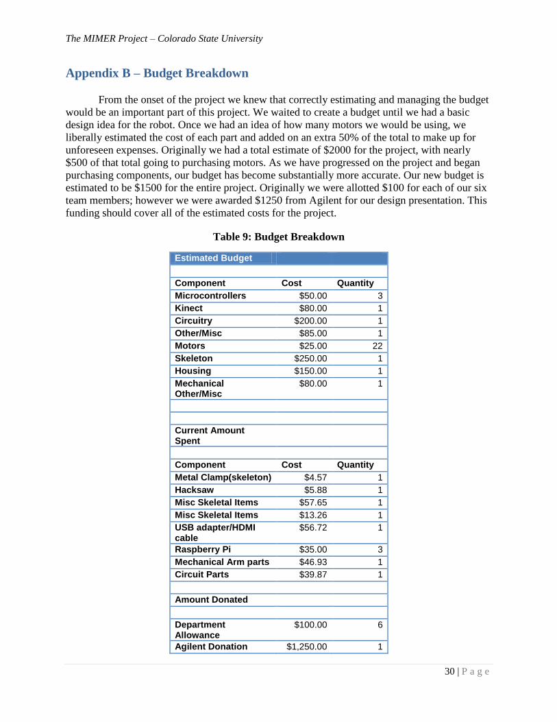
From the onset of the project we knew that correctly estimating and managing the budget
would be an important part of this project. We waited to create a budget until we had a basic
design idea for the robot. Once we had an idea of how many motors we would be using, we
liberally estimated the cost of each part and added on an extra 50% of the total to make up for
unforeseen expenses. Originally we had a total estimate of $2000 for the project, with nearly
$500 of that total going to purchasing motors. As we have progressed on the project and began
purchasing components, our budget has become substantially more accurate. Our new budget is
estimated to be $1500 for the entire project. Originally we were allotted $100 for each of our six
team members; however we were awarded $1250 from Agilent for our design presentation. This
funding should cover all of the estimated costs for the project.
Table 9: Budget Breakdown
Estimated Budget
Component Cost Quantity
Microcontrollers $50.00 3
Kinect $80.00 1
Circuitry $200.00 1
Other/Misc $85.00 1
Motors $25.00 22
Skeleton $250.00 1
Housing $150.00 1
Mechanical Other/Misc
$80.00 1
Current Amount Spent
Component Cost Quantity
Metal Clamp(skeleton) $4.57 1
Hacksaw $5.88 1
Misc Skeletal Items $57.65 1
Misc Skeletal Items $13.26 1
USB adapter/HDMI cable
$56.72 1
Raspberry Pi $35.00 3
Mechanical Arm parts $46.93 1
Circuit Parts $39.87 1
Amount Donated
Department Allowance
$100.00 6
Agilent Donation $1,250.00 1
The MIMER Project – Colorado State University
31 | P a g e
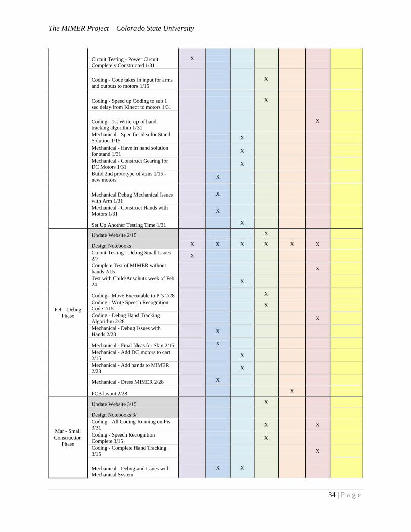
Appendix C
Current Timeline
Month
Assignment (Date to be Completed)
Salem Al-
Aqeel
John
Allison
Trevor
Pier
Jay
Vickers
Lucas
Wadman
Daniel
White Timeline
Met (Y/N)
Date Completed
June -
Research
Phase
Research on Body X Y
Microprocessor Selection X X Y
Kinect Data Output Stream X Y
July -
Research
Phase
3-D Movement Decision X X X X Y
Choose Size and Number of Motors X N
Design Hand X X X X N
Aug - Research
Phase
Prelim Tests X X X X N
How to Interface w/ Motors X X X X Y
Circuit Design X X X X Y
Sept -
Construction
Phase
Timeline 9/11 Email Sudeep TODAY X X X X X X Y
Background Writing Assignment 9/10 X X Y
Project Plan Presentation 9/24 X X Y
Project Website 9/18 Email Dr. Pasrcicha 9/11
X X X X X X Y
Revised Project Plan 9/23 X Y
Notebook Collection 9/23 X X X X X X Y
Update Website 9/15 X Y
Look Into Methods for Hand Tracking X Y
Find Sponsorship 10/1 X N
Materials Selected for Body 9/20 X Y
Overall Size - Sketches Completed
9/20 X
Y
Basic Skeleton Body Constructed 9/20 X Y
Choose Motor Types for Arm And
Order 10/5 X X
N
- Arm Movement Layout with Motors
10/5 X
Y
- Circuitry Layout with Motors Completed 10/5
X Y
Sensor Reselection (Webcams, Leap,
Kinect, Open NI Sensor) 10/1
X
Y
Microcontroller Reselection 9/15 X Y
Oct -
Construction
Phase
Testing and Measurement Plan 10/25
Email Sudeep 10/18
X
Y-N
Notebook Collection 10/14 Mech 10/3 X X X X X X Y
First Round of Concepts Complete
Mech 10/10 X X
Y
Design Your Future Day 10/16 X X X X X X Y
The MIMER Project – Colorado State University
32 | P a g e
Update Website 10/15 X Y
Project Presentation 10/25 X Y
Order Circuit Parts 11/3 X Y
Motors and Controller Interfacing 10/30 Completed Nov 2nd
X
N
Choose Motor Types for Arm and
Order 10/13 X
Y
Funding Letter Sent to Companies 10/11 finished 10/16
X
N
Preliminary Design Base for Robot
10/30 X
Y
Stuffing and shell for bear ideas 11/3 X Y
Sensor and Computer Testing 10/30 X Y
Start to Implement on Body 10/30 X Y
Nov - Debug
Phase
Oral Presentation 12/11 X X X X X X
First Round of Feasibility analysis started 11/14
X X Y 11-14
Notebook Check 11/14 Mech E 11/5 X X X X X X Y 11-14
Written Report 12/3 X
Elevator Speech 12/3 X
Plans for next Semester 12/3 X
Peer and Self Evaluation 12/3 X X X X X X
Update Website 11/15 X Y 11-15
Research Batteries for Battery
Powered 11/23 X
Y 11-10
Find another power supply to test
circuit 12/22 X
Order Circuit Parts 11/3 X Y 11-3
Stuffing and shell for bear ideas 11/3 X Y 11-3
Testing from Sensor to
Microcontroller 11/10 X
N 11-15
Code for Base 11/30 X Y 11-10
Dec -
Administration Phase
Oral Presentation 12/11 X
Critical Design Review Mech E 12/10 X X
Elevator Speech 12/3 X
Written Report 12/3 Mech 12/5 X
Design Notebooks 12/10 X X X X X X
Plans for next Semester 12/3 X
Peer and Self Evaluation 12/3 X X X X X X
Special Cases Coding 12/21 X
Rules for Use 12/21 X
Update Website 12/15 X
Set Up Time with Anschutz to Test 12/21
X
Circuit Testing - 2 solutions for
Voltage Regulation on Pis 12/22
X
The MIMER Project – Colorado State University
33 | P a g e
Circuit Testing - Fusing 12/31 X
Circuit Testing - Wall Switching to
Battery and Vice Versa 12/22
X
Y 11-13
Circuit Testing - Testing solutions for
voltage regulation 12/31
X
Coding - No Crashing Code 12/7 X
Coding - Bouncing motors is not
noticeable on arms 12/7
X
Coding - Debug of code for Pipeline 12/31
X X
Mechanical - Concept for Gearing of
DC Motor 12/31
X
Mechanical - Concept Design of
Hands Complete 12/31
X
Mechanical - Testing Torque of new
750mA motors 12/31 X
Mechanical - CAD final concept
drawing 12/11 X
Mechanical - Skin for testing 12/31 X
First Semester
Deliverables
Robot with moving arms taking input
from sensor and outputs to motors
X
- Prototypical Skeleton Design with
Motors X
Y
- Microcontroller Selection X Y 10-8
- Sensor Selection X Y 6-15
- 70% Code Completed - Arm
Mimicry, Speech Recognition, User
Selection
X
Y 11-23
- Meeting Clinical Criteria - Arm
Mirroring - no DC motors - no hands
X
- Slow Mimicry of Children (1 sec
Delay) X
- Power Circuit for Arms Completely Built
X N
- Speech Recognition Functionality
(moved to second semester)
X
N
Jan -
Construction Phase
Update Website 1/15 X
Test with Child Week of Jan 15th X
Revise Timeline 1/20 X
Circuit Testing - Solution for
discharging one end of the circuit and keeping a constant voltage wall and
battery 1/10
X
Circuit Testing - Testing solution for
discharging one end of the circuit and
keeping a constant voltage - wall and battery 1/15
X
The MIMER Project – Colorado State University
34 | P a g e
Circuit Testing - Power Circuit Completely Constructed 1/31
X
Coding - Code takes in input for arms
and outputs to motors 1/15
X
Coding - Speed up Coding to sub 1
sec delay from Kinect to motors 1/31
X
Coding - 1st Write-up of hand tracking algorithm 1/31
X
Mechanical - Specific Idea for Stand
Solution 1/15 X
Mechanical - Have in hand solution
for stand 1/31 X
Mechanical - Construct Gearing for DC Motors 1/31
X
Build 2nd prototype of arms 1/15 -
new motors X
Mechanical Debug Mechanical Issues with Arm 1/31
X
Mechanical - Construct Hands with
Motors 1/31 X
Set Up Another Testing Time 1/31 X
Feb - Debug
Phase
Update Website 2/15 X
Design Notebooks X X X X X X
Circuit Testing - Debug Small Issues 2/7
X
Complete Test of MIMER without
hands 2/15 X
Test with Child/Anschutz week of Feb
24 X
Coding - Move Executable to Pi's 2/28 X
Coding - Write Speech Recognition
Code 2/15 X
Coding - Debug Hand Tracking Algorithm 2/28
X
Mechanical - Debug Issues with
Hands 2/28 X
Mechanical - Final Ideas for Skin 2/15 X
Mechanical - Add DC motors to cart
2/15 X
Mechanical - Add hands to MIMER
2/28 X
Mechanical - Dress MIMER 2/28 X
PCB layout 2/28 X
Mar - Small
Construction
Phase
Update Website 3/15 X
Design Notebooks 3/
Coding - All Coding Running on Pis
3/31 X X
Coding - Speech Recognition Complete 3/15
X
Coding - Complete Hand Tracking
3/15 X
Mechanical - Debug and Issues with Mechanical System
X X
The MIMER Project – Colorado State University
35 | P a g e
Circuit - Debug Any Issues with
Electrical System X X
Meet All Final Deliverables 3/31 X
Apr - Last
Debug Phase
Written Report X
Recommendation for Project
Continuation X X
Edays X
Peer and Self Evaluation X X X X X X
Oral Presentation X
Any Last Debug X X X X X X
Second
Semester
Deliverables
Final Complete Project X X X X X X
Arms Mirroring Child X X X X X X
Hands Mirroring Child X X X X X X
Aesthically Pleasing X X X X X X
Exceeds all of Anschutz's
Expectations X X X X X X
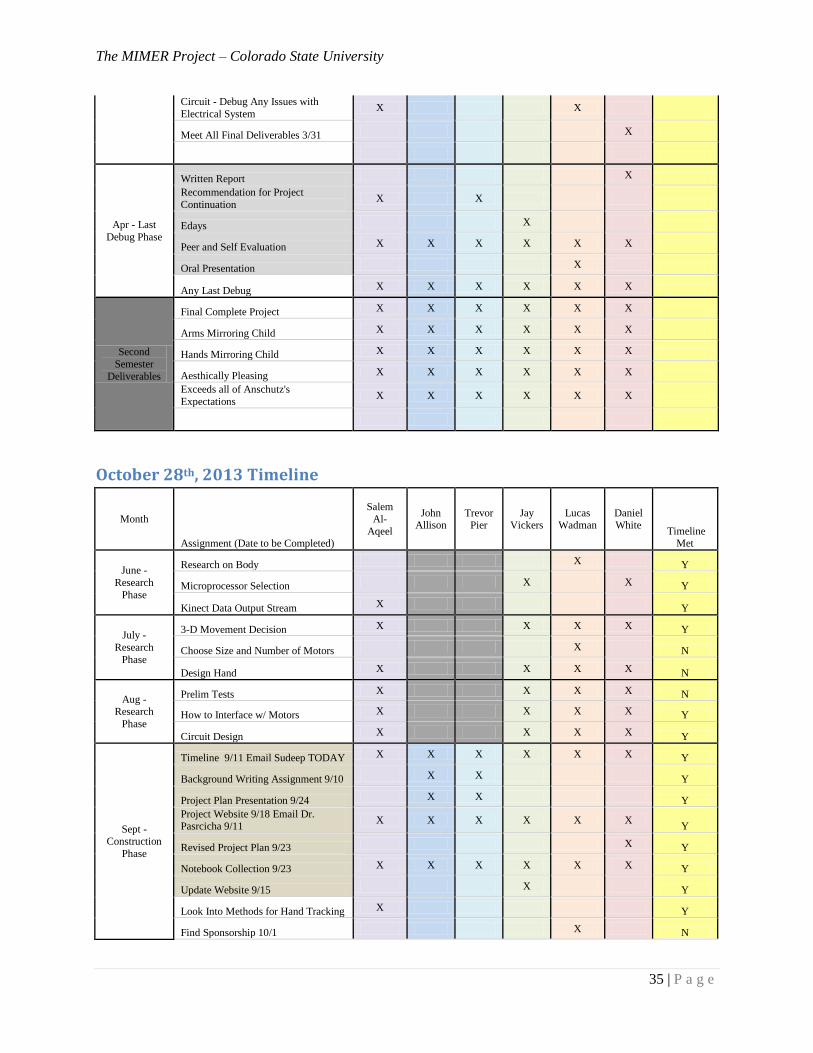
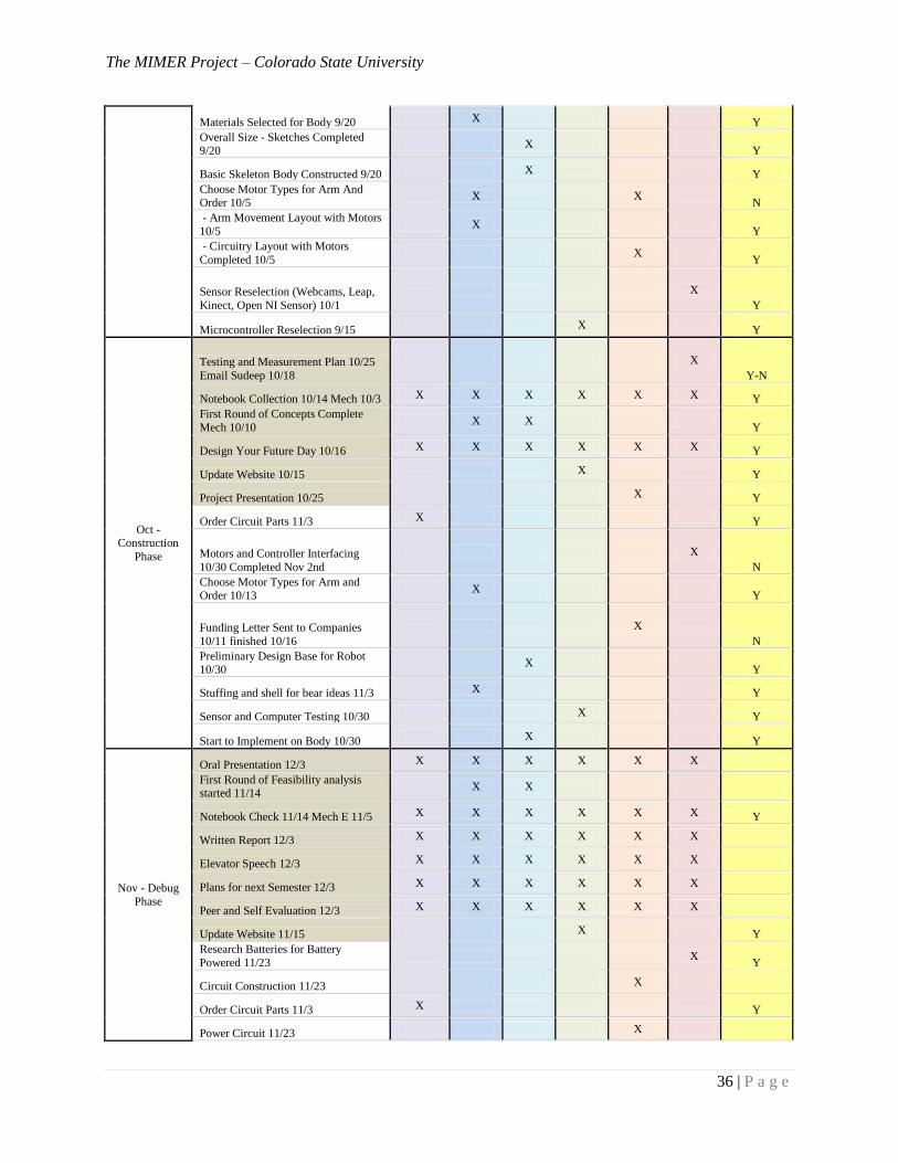
October 28th, 2013 Timeline
Month
Assignment (Date to be Completed)
Salem
Al-
Aqeel
John Allison
Trevor Pier
Jay Vickers
Lucas Wadman
Daniel White
Timeline Met
June -
Research
Phase
Research on Body X Y
Microprocessor Selection X X Y
Kinect Data Output Stream X Y
July -
Research
Phase
3-D Movement Decision X X X X Y
Choose Size and Number of Motors X N
Design Hand X X X X N
Aug - Research
Phase
Prelim Tests X X X X N
How to Interface w/ Motors X X X X Y
Circuit Design X X X X Y
Sept - Construction
Phase
Timeline 9/11 Email Sudeep TODAY X X X X X X Y
Background Writing Assignment 9/10 X X Y
Project Plan Presentation 9/24 X X Y
Project Website 9/18 Email Dr. Pasrcicha 9/11
X X X X X X Y
Revised Project Plan 9/23 X Y
Notebook Collection 9/23 X X X X X X Y
Update Website 9/15 X Y
Look Into Methods for Hand Tracking X Y
Find Sponsorship 10/1 X N
The MIMER Project – Colorado State University
36 | P a g e
Materials Selected for Body 9/20 X Y
Overall Size - Sketches Completed 9/20
X Y
Basic Skeleton Body Constructed 9/20 X Y
Choose Motor Types for Arm And Order 10/5
X X N
- Arm Movement Layout with Motors
10/5 X
Y
- Circuitry Layout with Motors
Completed 10/5 X
Y
Sensor Reselection (Webcams, Leap,
Kinect, Open NI Sensor) 10/1
X
Y
Microcontroller Reselection 9/15 X Y
Oct - Construction
Phase
Testing and Measurement Plan 10/25
Email Sudeep 10/18
X
Y-N
Notebook Collection 10/14 Mech 10/3 X X X X X X Y
First Round of Concepts Complete
Mech 10/10 X X
Y
Design Your Future Day 10/16 X X X X X X Y
Update Website 10/15 X Y
Project Presentation 10/25 X Y
Order Circuit Parts 11/3 X Y
Motors and Controller Interfacing
10/30 Completed Nov 2nd
X
N
Choose Motor Types for Arm and Order 10/13
X Y
Funding Letter Sent to Companies
10/11 finished 10/16
X
N
Preliminary Design Base for Robot 10/30
X Y
Stuffing and shell for bear ideas 11/3 X Y
Sensor and Computer Testing 10/30 X Y
Start to Implement on Body 10/30 X Y
Nov - Debug
Phase
Oral Presentation 12/3 X X X X X X
First Round of Feasibility analysis started 11/14
X X
Notebook Check 11/14 Mech E 11/5 X X X X X X Y
Written Report 12/3 X X X X X X
Elevator Speech 12/3 X X X X X X
Plans for next Semester 12/3 X X X X X X
Peer and Self Evaluation 12/3 X X X X X X
Update Website 11/15 X Y
Research Batteries for Battery
Powered 11/23 X
Y
Circuit Construction 11/23 X
Order Circuit Parts 11/3 X Y
Power Circuit 11/23 X
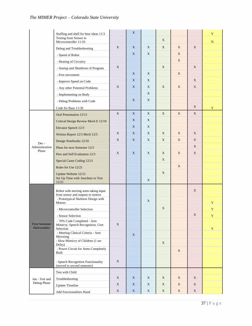
The MIMER Project – Colorado State University
37 | P a g e
Stuffing and shell for bear ideas 11/3 X Y
Testing from Sensor to
Microcontroller 11/10 X
N
Debug and Troubleshooting X X X X X X
- Speed of Robot X X X
- Heating of Circuitry X
- Startup and Shutdown of Program X X X
- Free movement X X X
- Improve Speed on Code X X X
- Any other Potential Problems X X X X X X
- Implementing on Body X
- Debug Problems with Code X X
Code for Base 11/30 X Y
Dec -
Administration Phase
Oral Presentation 12/11 X X X X X X
Critical Design Review Mech E 12/10 X X
Elevator Speech 12/3 X X
Written Report 12/3 Mech 12/5 X X X X X X
Design Notebooks 12/10 X X X X X X
Plans for next Semester 12/3 X
Peer and Self Evaluation 12/3 X X X X X X
Special Cases Coding 12/21 X
Rules for Use 12/21 X
Update Website 12/15 X
Set Up Time with Anschutz to Test
12/21 X
First Semester
Deliverables
Robot with moving arms taking input
from sensor and outputs to motors
X
- Prototypical Skeleton Design with
Motors X
Y
- Microcontroller Selection X Y
- Sensor Selection X Y
- 70% Code Completed - Arm
Mimicry, Speech Recognition, User
Selection
X
Y
- Meeting Clinical Criteria - Arm Mirroring
X
- Slow Mimicry of Children (1 sec
Delay) X
- Power Circuit for Arms Completely
Built X
- Speech Recognition Functionality
(moved to second semester)
X
Jan - Test and
Debug Phase
Test with Child
Troubleshooting X X X X X X
Update Timeline X X X X X X
Add Functionalities Hand X X X X X X
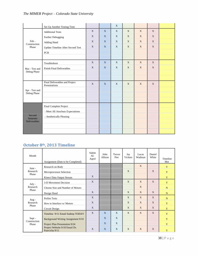
The MIMER Project – Colorado State University
38 | P a g e
Set Up Another Testing Time X
Feb - Construction
Phase
Additional Tests X X X X X X
Further Debugging X X X X X X
Adding Hand X X X X X X
Update Timeline After Second Test X X X X X X
PCB
Mar - Test and Debug Phase
Troubleshoot X X X X X X
Finish Final Deliverables X X X X X X
Apr - Test and Debug Phase
Final Deliverables and Project
Presentations X X X X X X
Second
Semester
Deliverables
Final Complete Project
- Meet All Anschutz Expectations
- Aesthetically Pleasing
October 8th, 2013 Timeline
Month
Assignment (Date to be Completed)
Salem Al-
Aqeel
John
Allison
Trevor
Pier
Jay
Vickers
Lucas
Wadman
Daniel
White Timeline
Met
June - Research
Phase
Research on Body X Y
Microprocessor Selection X X Y
Kinect Data Output Stream X Y
July - Research
Phase
3-D Movement Decision X X X X Y
Choose Size and Number of Motors X N
Design Hand X X X X N
Aug -
Research Phase
Prelim Tests X X X X N
How to Interface w/ Motors X X X X Y
Circuit Design X X X X Y
Sept - Construction
Phase
Timeline 9/11 Email Sudeep TODAY X X X X X X Y
Background Writing Assignment 9/10 X X Y
Project Plan Presentation 9/24 X X Y
Project Website 9/18 Email Dr.
Pasrcicha 9/11 X X X X X X
Y
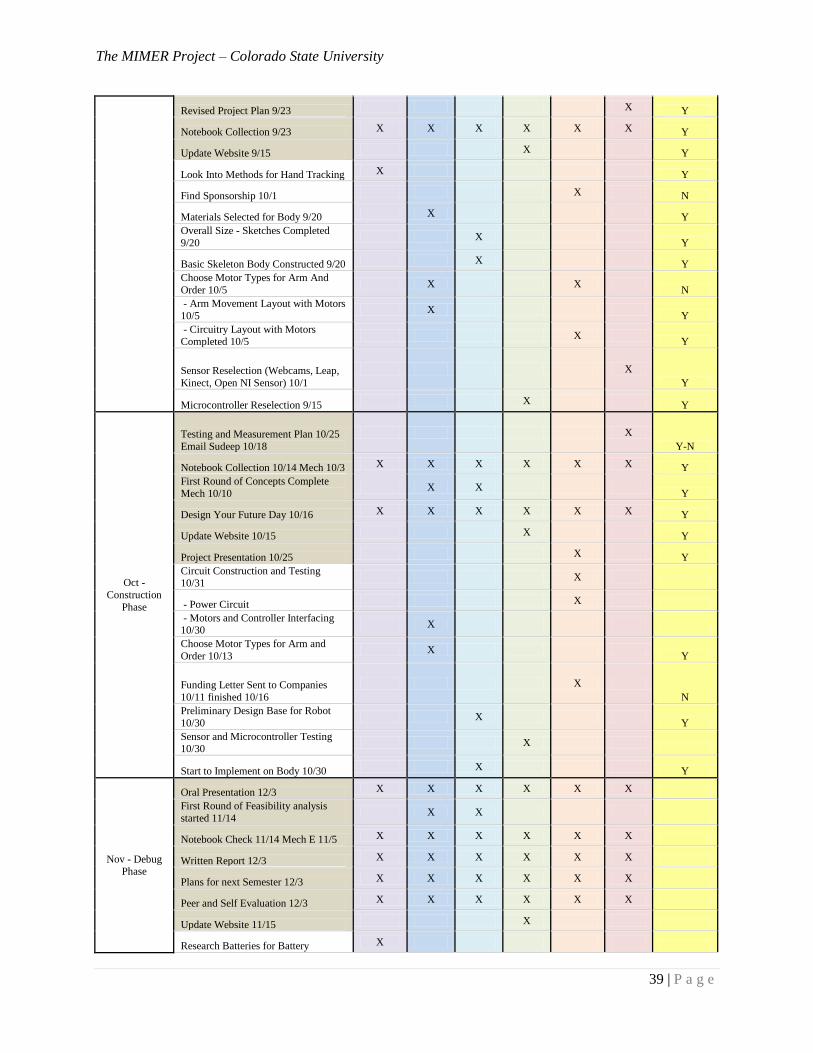
The MIMER Project – Colorado State University
39 | P a g e
Revised Project Plan 9/23 X Y
Notebook Collection 9/23 X X X X X X Y
Update Website 9/15 X Y
Look Into Methods for Hand Tracking X Y
Find Sponsorship 10/1 X N
Materials Selected for Body 9/20 X Y
Overall Size - Sketches Completed
9/20 X
Y
Basic Skeleton Body Constructed 9/20 X Y
Choose Motor Types for Arm And
Order 10/5 X X
N
- Arm Movement Layout with Motors
10/5 X
Y
- Circuitry Layout with Motors
Completed 10/5 X
Y
Sensor Reselection (Webcams, Leap,
Kinect, Open NI Sensor) 10/1
X
Y
Microcontroller Reselection 9/15 X Y
Oct -
Construction
Phase
Testing and Measurement Plan 10/25
Email Sudeep 10/18
X
Y-N
Notebook Collection 10/14 Mech 10/3 X X X X X X Y
First Round of Concepts Complete
Mech 10/10 X X
Y
Design Your Future Day 10/16 X X X X X X Y
Update Website 10/15 X Y
Project Presentation 10/25 X Y
Circuit Construction and Testing 10/31
X
- Power Circuit X
- Motors and Controller Interfacing 10/30
X
Choose Motor Types for Arm and
Order 10/13 X
Y
Funding Letter Sent to Companies
10/11 finished 10/16
X
N
Preliminary Design Base for Robot
10/30 X
Y
Sensor and Microcontroller Testing 10/30
X
Start to Implement on Body 10/30 X Y
Nov - Debug Phase
Oral Presentation 12/3 X X X X X X
First Round of Feasibility analysis
started 11/14 X X
Notebook Check 11/14 Mech E 11/5 X X X X X X
Written Report 12/3 X X X X X X
Plans for next Semester 12/3 X X X X X X
Peer and Self Evaluation 12/3 X X X X X X
Update Website 11/15 X
Research Batteries for Battery X
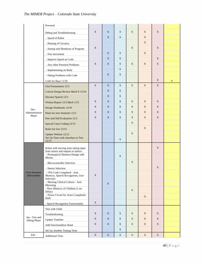
The MIMER Project – Colorado State University
40 | P a g e
Powered
Debug and Troubleshooting X X X X X X
- Speed of Robot X X X
- Heating of Circuitry X
- Startup and Shutdown of Program X X X
- Free movement X X X
- Improve Speed on Code X X X
- Any other Potential Problems X X X X X X
- Implementing on Body X
- Debug Problems with Code X X
Code for Base 11/30 X Y
Dec -
Administration
Phase
Oral Presentation 12/3 X X X X X X
Critical Design Review Mech E 12/10 X X
Elevator Speech 12/3 X X
Written Report 12/3 Mech 12/5 X X X X X X
Design Notebooks 12/10 X X X X X X
Plans for next Semester 12/3 X X X X X X
Peer and Self Evaluation 12/3 X X X X X X
Special Cases Coding 12/15 X
Rules for Use 12/15 X
Update Website 12/15 X
Set Up Time with Anschutz to Test
12/15 X
First Semester
Deliverables
Robot with moving arms taking input from sensor and outputs to motors
X
- Prototypical Skeleton Design with
Motors X
- Microcontroller Selection X
- Sensor Selection X
- 70% Code Completed - Arm Mimicry, Speech Recognition, User
Selection
X
- Meeting Clinical Criteria - Arm
Mirroring X
- Slow Mimicry of Children (1 sec Delay)
X
- Power Circuit for Arms Completely
Built X
- Speech Recognition Functionality X
Jan - Test and
Debug Phase
Test with Child
Troubleshooting X X X X X X
Update Timeline X X X X X X
Add Functionalities Hand X X X X X X
Set Up Another Testing Time X
Feb - Additional Tests X X X X X X
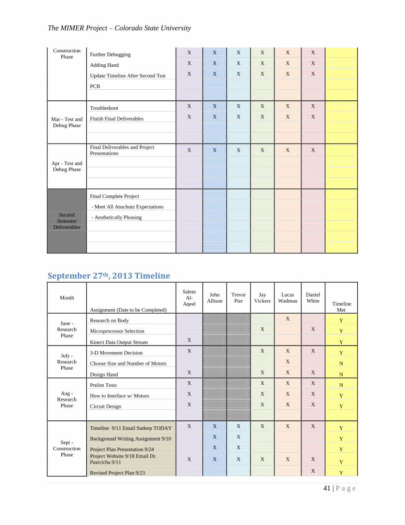
The MIMER Project – Colorado State University
41 | P a g e
Construction
Phase Further Debugging X X X X X X
Adding Hand X X X X X X
Update Timeline After Second Test X X X X X X
PCB
Mar - Test and
Debug Phase
Troubleshoot X X X X X X
Finish Final Deliverables X X X X X X
Apr - Test and
Debug Phase
Final Deliverables and Project Presentations
X X X X X X
Second
Semester
Deliverables
Final Complete Project
- Meet All Anschutz Expectations
- Aesthetically Pleasing
September 27th, 2013 Timeline
Month
Assignment (Date to be Completed)
Salem Al-
Aqeel
John
Allison
Trevor
Pier
Jay
Vickers
Lucas
Wadman
Daniel
White Timeline
Met
June - Research
Phase
Research on Body X Y
Microprocessor Selection X X Y
Kinect Data Output Stream X Y
July -
Research Phase
3-D Movement Decision X X X X Y
Choose Size and Number of Motors X N
Design Hand X X X X N
Aug - Research
Phase
Prelim Tests X X X X N
How to Interface w/ Motors X X X X Y
Circuit Design X X X X Y
Sept -
Construction Phase
Timeline 9/11 Email Sudeep TODAY X X X X X X Y
Background Writing Assignment 9/10 X X Y
Project Plan Presentation 9/24 X X Y
Project Website 9/18 Email Dr. Pasrcicha 9/11
X X X X X X Y
Revised Project Plan 9/23 X Y
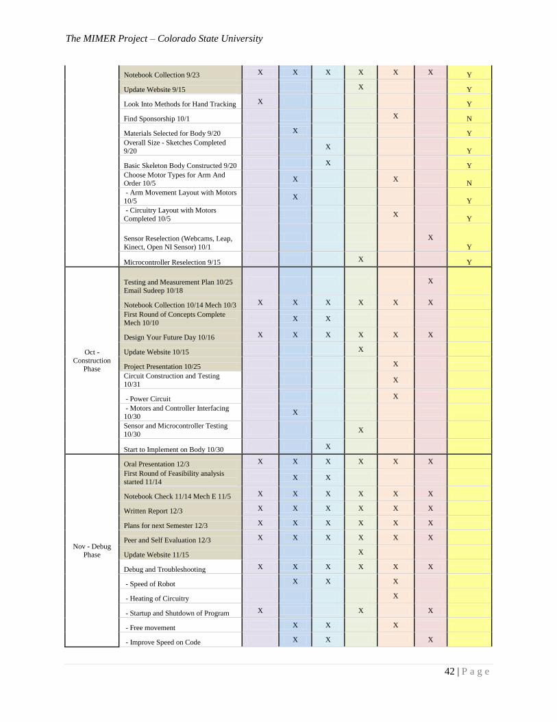
The MIMER Project – Colorado State University
42 | P a g e
Notebook Collection 9/23 X X X X X X Y
Update Website 9/15 X Y
Look Into Methods for Hand Tracking X Y
Find Sponsorship 10/1 X N
Materials Selected for Body 9/20 X Y
Overall Size - Sketches Completed 9/20
X Y
Basic Skeleton Body Constructed 9/20 X Y
Choose Motor Types for Arm And Order 10/5
X X N
- Arm Movement Layout with Motors
10/5 X
Y
- Circuitry Layout with Motors
Completed 10/5 X
Y
Sensor Reselection (Webcams, Leap,
Kinect, Open NI Sensor) 10/1
X
Y
Microcontroller Reselection 9/15 X Y
Oct -
Construction Phase
Testing and Measurement Plan 10/25
Email Sudeep 10/18
X
Notebook Collection 10/14 Mech 10/3 X X X X X X
First Round of Concepts Complete
Mech 10/10 X X
Design Your Future Day 10/16 X X X X X X
Update Website 10/15 X
Project Presentation 10/25 X
Circuit Construction and Testing
10/31 X
- Power Circuit X
- Motors and Controller Interfacing 10/30
X
Sensor and Microcontroller Testing
10/30 X
Start to Implement on Body 10/30 X
Nov - Debug Phase
Oral Presentation 12/3 X X X X X X
First Round of Feasibility analysis
started 11/14 X X
Notebook Check 11/14 Mech E 11/5 X X X X X X
Written Report 12/3 X X X X X X
Plans for next Semester 12/3 X X X X X X
Peer and Self Evaluation 12/3 X X X X X X
Update Website 11/15 X
Debug and Troubleshooting X X X X X X
- Speed of Robot X X X
- Heating of Circuitry X
- Startup and Shutdown of Program X X X
- Free movement X X X
- Improve Speed on Code X X X
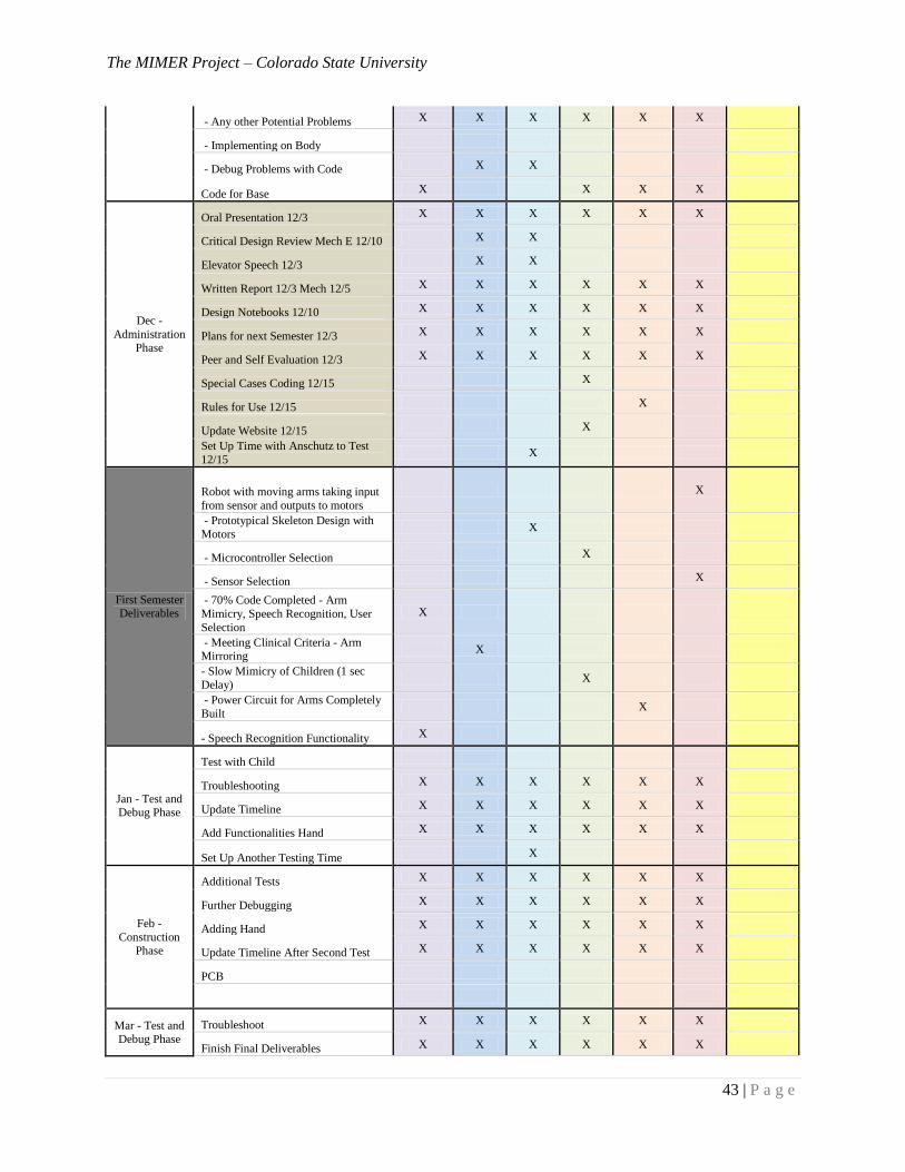
The MIMER Project – Colorado State University
43 | P a g e
- Any other Potential Problems X X X X X X
- Implementing on Body
- Debug Problems with Code X X
Code for Base X X X X
Dec -
Administration Phase
Oral Presentation 12/3 X X X X X X
Critical Design Review Mech E 12/10 X X
Elevator Speech 12/3 X X
Written Report 12/3 Mech 12/5 X X X X X X
Design Notebooks 12/10 X X X X X X
Plans for next Semester 12/3 X X X X X X
Peer and Self Evaluation 12/3 X X X X X X
Special Cases Coding 12/15 X
Rules for Use 12/15 X
Update Website 12/15 X
Set Up Time with Anschutz to Test
12/15 X
First Semester Deliverables
Robot with moving arms taking input
from sensor and outputs to motors
X
- Prototypical Skeleton Design with
Motors X
- Microcontroller Selection X
- Sensor Selection X
- 70% Code Completed - Arm
Mimicry, Speech Recognition, User
Selection
X
- Meeting Clinical Criteria - Arm Mirroring
X
- Slow Mimicry of Children (1 sec
Delay) X
- Power Circuit for Arms Completely
Built X
- Speech Recognition Functionality X
Jan - Test and Debug Phase
Test with Child
Troubleshooting X X X X X X
Update Timeline X X X X X X
Add Functionalities Hand X X X X X X
Set Up Another Testing Time X
Feb -
Construction Phase
Additional Tests X X X X X X
Further Debugging X X X X X X
Adding Hand X X X X X X
Update Timeline After Second Test X X X X X X
PCB
Mar - Test and Debug Phase
Troubleshoot X X X X X X
Finish Final Deliverables X X X X X X
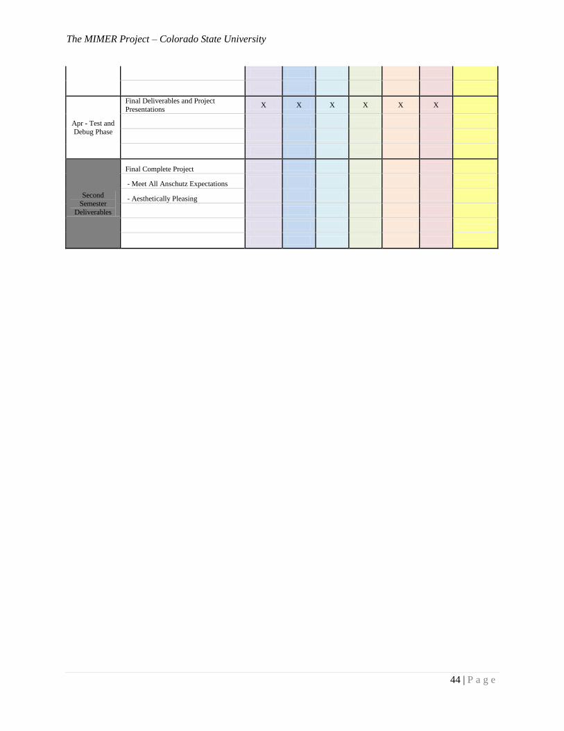
The MIMER Project – Colorado State University
44 | P a g e
Apr - Test and
Debug Phase
Final Deliverables and Project
Presentations X X X X X X
Second Semester
Deliverables
Final Complete Project
- Meet All Anschutz Expectations
- Aesthetically Pleasing
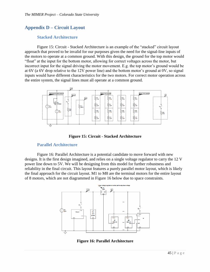
The MIMER Project – Colorado State University
45 | P a g e
Appendix D – Circuit Layout
Stacked Architecture
Figure 15: Circuit - Stacked Architecture is an example of the “stacked” circuit layout
approach that proved to be invalid for our purposes given the need for the signal-line inputs of
the motors to operate at a common ground. With this design, the ground for the top motor would
“float” at the input for the bottom motor, allowing for correct voltages across the motor, but
incorrect input for the signal driving the motor movement. E.g. the top motor’s ground would be
at 6V (a 6V drop relative to the 12V power line) and the bottom motor’s ground at 0V, so signal
inputs would have different characteristics for the two motors. For correct motor operation across
the entire system, the signal lines must all operate at a common ground.
Figure 15: Circuit - Stacked Architecture
Parallel Architecture
Figure 16: Parallel Architecture is a potential candidate to move forward with new
designs. It is the first design imagined, and relies on a single voltage regulator to carry the 12 V
power line down to 5V. We will be designing from this model for further robustness and
reliability in the final circuit. This layout features a purely parallel motor layout, which is likely
the final approach for the circuit layout. M1 to M8 are the terminal motors for the entire layout
of 8 motors, which are not diagrammed in Figure 16 below due to space constraints.
Figure 16: Parallel Architecture
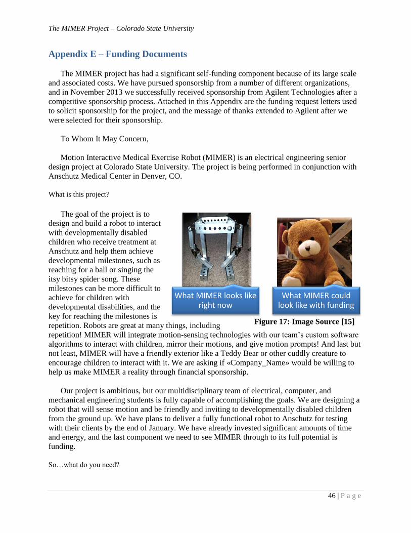
The MIMER Project – Colorado State University
46 | P a g e
Appendix E – Funding Documents
The MIMER project has had a significant self-funding component because of its large scale
and associated costs. We have pursued sponsorship from a number of different organizations,
and in November 2013 we successfully received sponsorship from Agilent Technologies after a
competitive sponsorship process. Attached in this Appendix are the funding request letters used
to solicit sponsorship for the project, and the message of thanks extended to Agilent after we
were selected for their sponsorship.
To Whom It May Concern,
Motion Interactive Medical Exercise Robot (MIMER) is an electrical engineering senior
design project at Colorado State University. The project is being performed in conjunction with
Anschutz Medical Center in Denver, CO.
What is this project?
The goal of the project is to
design and build a robot to interact
with developmentally disabled
children who receive treatment at
Anschutz and help them achieve
developmental milestones, such as
reaching for a ball or singing the
itsy bitsy spider song. These
milestones can be more difficult to
achieve for children with
developmental disabilities, and the
key for reaching the milestones is
repetition. Robots are great at many things, including
repetition! MIMER will integrate motion-sensing technologies with our team’s custom software
algorithms to interact with children, mirror their motions, and give motion prompts! And last but
not least, MIMER will have a friendly exterior like a Teddy Bear or other cuddly creature to
encourage children to interact with it. We are asking if «Company_Name» would be willing to
help us make MIMER a reality through financial sponsorship.
Our project is ambitious, but our multidisciplinary team of electrical, computer, and
mechanical engineering students is fully capable of accomplishing the goals. We are designing a
robot that will sense motion and be friendly and inviting to developmentally disabled children
from the ground up. We have plans to deliver a fully functional robot to Anschutz for testing
with their clients by the end of January. We have already invested significant amounts of time
and energy, and the last component we need to see MIMER through to its full potential is
funding.
So…what do you need?
What MIMER looks like right now
What MIMER could look like with funding
Figure 17: Image Source [15]
The MIMER Project – Colorado State University
47 | P a g e
At this point, our project is in need of funding resources so we can purchase the advanced
sensor technologies, robot components, and other components as we encounter project bumps.
We currently anticipate needing a total sponsorship of $2000 for our project, so any funding your
organization could provide would be appreciated greatly. A detailed budget breakdown is
available by request. Donations will be made through a secure web portal on the Electrical and
Computer Engineering web page.
How will this benefit «Company_Name»?
There are a number of ways in which
sponsorship would benefit
«Company_Name». This project will have
exposure not just throughout Colorado
State University through our coursework
but also within the Fort Collins and
Anschutz communities when we are
eventually running trial tests with the robot.
If «Company_Name» were to offer
assistance for our project, we would be sure
to prominently include your branding on our team shirts, deliverables like our paper and
presentation, or even on the MIMER robot itself.
We from the MIMER team thank you at «Company_Name» for your time and consideration
of this funding request. If you have any questions, please contact our fundraising lead, Luke
Wadman ([email protected]), our faculty advisor, Dr. Sudeep Pasricha
([email protected]), or the head of ECE senior design, Olivera Notaros
([email protected]). You can find more information at our project web page
(http://www.engr.colostate.edu/ece-sr-design/AY13/MIMER/index.html).
Sincerely,
Electrical and Computer Engineering MIMERS Mechanical Engineering MIMERS
Salem Al-Aqeel, Daniel White, Jay Vickers, Luke Wadman John Allison, Trevor Pier
MIMER, ready to reshape care
techniques for developmental
disabilities...with your help!

The MIMER Project – Colorado State University
48 | P a g e
Appendix F – Thank You Letter
To Dan Ferguson, Mike Craig, and Mike Hawes and the Agilent Team,
We would like to extend our thanks to your team of Dan Ferguson, Mike Craig, and Mike
Hawes, and the rest of the Agilent organization for selecting our Motion Interactive Medical
Exercise Robot (MIMER) senior design project as 1st place in the 2013 Agilent Senior Design
sponsorship competition!
This sponsorship allows us the opportunity to see our project through to completion, without
unnecessary hiccups or financial obligations to our individual team members. This is the kind of
flexibility our small team needs, and it will allow us to fully realize the potential of our project
by the end of next April.
With this generous sponsorship from Agilent, we are committed to including Agilent logos
and thanks on all our project materials, including reports, presentations, and our website. In
addition, we will be working with a member of the sponsorship committee to organize a site visit
to Agilent in the spring time frame, when MIMER will be demonstration-ready. We will also be
relaying Agilent’s generous status to our collaborators at Anschutz Medical Center.
We are enormously excited that Agilent is committed to MIMER, the next generation
apparatus for measuring effective treatment of developmental disabilities in a clinical
environment. With Agilent’s sponsorship, we are that much closer to helping Anschutz’s team of
expert clinicians usher in a new era of diagnosing, treating, and rehabilitating children with
developmental disabilities.
We again extend our humble thanks, and look forward to working with you in the future as
MIMER comes closer to a reality.
Sincerely,
Electrical and Computer Engineering MIMERS Mechanical Engineering MIMERS
Salem Al-Aqeel, Daniel White, Jay Vickers, Luke Wadman John Allison, Trevor Pier
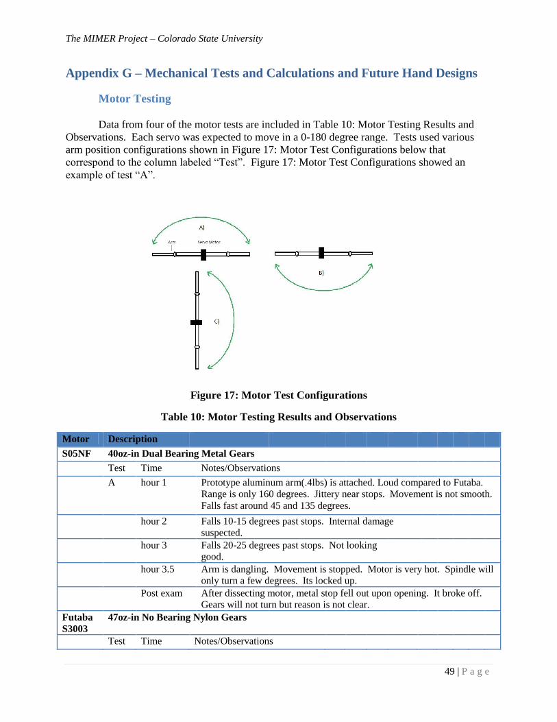
The MIMER Project – Colorado State University
49 | P a g e
Appendix G – Mechanical Tests and Calculations and Future Hand Designs
Motor Testing
Data from four of the motor tests are included in Table 10: Motor Testing Results and
Observations. Each servo was expected to move in a 0-180 degree range. Tests used various
arm position configurations shown in Figure 17: Motor Test Configurations below that
correspond to the column labeled “Test”. Figure 17: Motor Test Configurations showed an
example of test “A”.
Figure 17: Motor Test Configurations
Table 10: Motor Testing Results and Observations
Motor Description
S05NF 40oz-in Dual Bearing Metal Gears
Test Time Notes/Observations
A
hour 1 Prototype aluminum arm(.4lbs) is attached. Loud compared to Futaba.
Range is only 160 degrees. Jittery near stops. Movement is not smooth.
Falls fast around 45 and 135 degrees.
hour 2 Falls 10-15 degrees past stops. Internal damage
suspected.
hour 3 Falls 20-25 degrees past stops. Not looking
good.
hour 3.5 Arm is dangling. Movement is stopped. Motor is very hot. Spindle will
only turn a few degrees. Its locked up.
Post exam After dissecting motor, metal stop fell out upon opening. It broke off.
Gears will not turn but reason is not clear.
Futaba
S3003
47oz-in No Bearing Nylon Gears
Test Time Notes/Observations
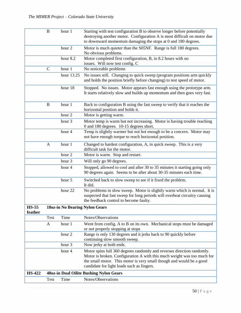
The MIMER Project – Colorado State University
50 | P a g e
B
hour 1 Starting with test configuration B to observe longer before potentially
destroying another motor. Configuration A is most difficult on motor due
to downward momentum damaging the stops at 0 and 180 degrees.
hour 2 Motor is much quieter than the S05NF. Range is full 180 degrees.
No obvious problems.
hour 8.2 Motor completed first configuration, B, in 8.2 hours with no
issues. Will now test config. C
C hour 1 No noticeable problems
hour 13.25 No issues still. Changing to quick sweep (program positions arm quickly
and holds the position briefly before changing) to test speed of motor.
hour 18
Stopped. No issues. Motor appears fast enough using the prototype arm.
It starts relatively slow and builds up momentum and then goes very fast.
B hour 1 Back to configuration B using the fast sweep to verify that it reaches the
horizontal position and holds it.
hour 2 Motor is getting warm.
hour 3 Motor temp is warm but not increasing. Motor is having trouble reaching
0 and 180 degrees. 10-15 degrees short.
hour 4
Temp is slightly warmer but not hot enough to be a concern. Motor may
not have enough torque to reach horizontal position.
A hour 1 Changed to hardest configuration, A, in quick sweep. This is a very
difficult task for the motor.
hour 2 Motor is warm. Stop and restart.
hour 3 Will only go 90 degrees.
hour 4 Stopped, allowed to cool and after 30 to 35 minutes it starting going only
90 degrees again. Seems to be after about 30-35 minutes each time.
hour 5 Switched back to slow sweep to see if it fixed the problem.
It did.
hour 22
No problems in slow sweep. Motor is slightly warm which is normal. It is
suspected that fast sweep for long periods will overheat circuitry causing
the feedback control to become faulty.
HS-55
feather
18oz-in No Bearing Nylon Gears
Test Time Notes/Observations
A hour 1 Went from config. A to B on its own. Mechanical stops must be damaged
or not properly stopping at stops
hour 2 Range is only 130 degrees and it jerks back to 90 quickly before
continuing slow smooth sweep.
hour 3 Now jerky at both ends.
hour 4
Motor spins full 360 degrees randomly and reverses direction randomly.
Motor is broken. Configuration A with this much weight was too much for
the small motor. This motor is very small though and would be a good
candidate for light loads such as fingers.
HS-422 48oz-in Dual Oilite Bushing Nylon Gears
Test Time Notes/Observations
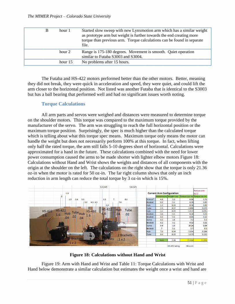
The MIMER Project – Colorado State University
51 | P a g e
B
hour 1 Started slow sweep with new Lynxmotion arm which has a similar weight
as prototype arm but weight is further towards the end creating more
torque than previous arm. Torque calculations can be found in separate
file.
hour 2 Range is 175-180 degrees. Movement is smooth. Quiet operation
similar to Futaba S3003 and S3004.
hour 15 No problems after 15 hours.
The Futaba and HS-422 motors performed better than the other motors. Better, meaning
they did not break, they were quick in acceleration and speed, they were quiet, and could lift the
arm closer to the horizontal position. Not listed was another Futaba that is identical to the S3003
but has a ball bearing that performed well and had no significant issues worth noting.
Torque Calculations
All arm parts and servos were weighed and distances were measured to determine torque
on the shoulder motors. This torque was compared to the maximum torque provided by the
manufacturer of the servo. The arm was struggling to reach the full horizontal position or the
maximum torque position. Surprisingly, the spec is much higher than the calculated torque
which is telling about what this torque spec means. Maximum torque only means the motor can
handle the weight but does not necessarily perform 100% at this torque. In fact, when lifting
only half the rated torque, the arm still falls 5-10 degrees short of horizontal. Calculations were
approximated for a hand in the future. These calculations combined with the need for lower
power consumption caused the arms to be made shorter with lighter elbow motors Figure 18:
Calculations without Hand and Wrist shows the weights and distances of all components with the
origin at the shoulder on the left. The calculations on the right show that the torque is only 21.36
oz-in when the motor is rated for 50 oz-in. The far right column shows that only an inch
reduction in arm length can reduce the total torque by 3 oz-in which is 15%.
Figure 18: Calculations without Hand and Wrist
Figure 19: Arm with Hand and Wrist and Table 11: Torque Calculations with Wrist and
Hand below demonstrate a similar calculation but estimates the weight once a wrist and hand are
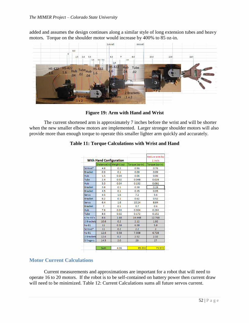
The MIMER Project – Colorado State University
52 | P a g e
added and assumes the design continues along a similar style of long extension tubes and heavy
motors. Torque on the shoulder motor would increase by 400% to 85 oz-in.
Figure 19: Arm with Hand and Wrist
The current shortened arm is approximately 7 inches before the wrist and will be shorter
when the new smaller elbow motors are implemented. Larger stronger shoulder motors will also
provide more than enough torque to operate this smaller lighter arm quickly and accurately.
Table 11: Torque Calculations with Wrist and Hand
Motor Current Calculations
Current measurements and approximations are important for a robot that will need to
operate 16 to 20 motors. If the robot is to be self-contained on battery power then current draw
will need to be minimized. Table 12: Current Calculations sums all future servos current.
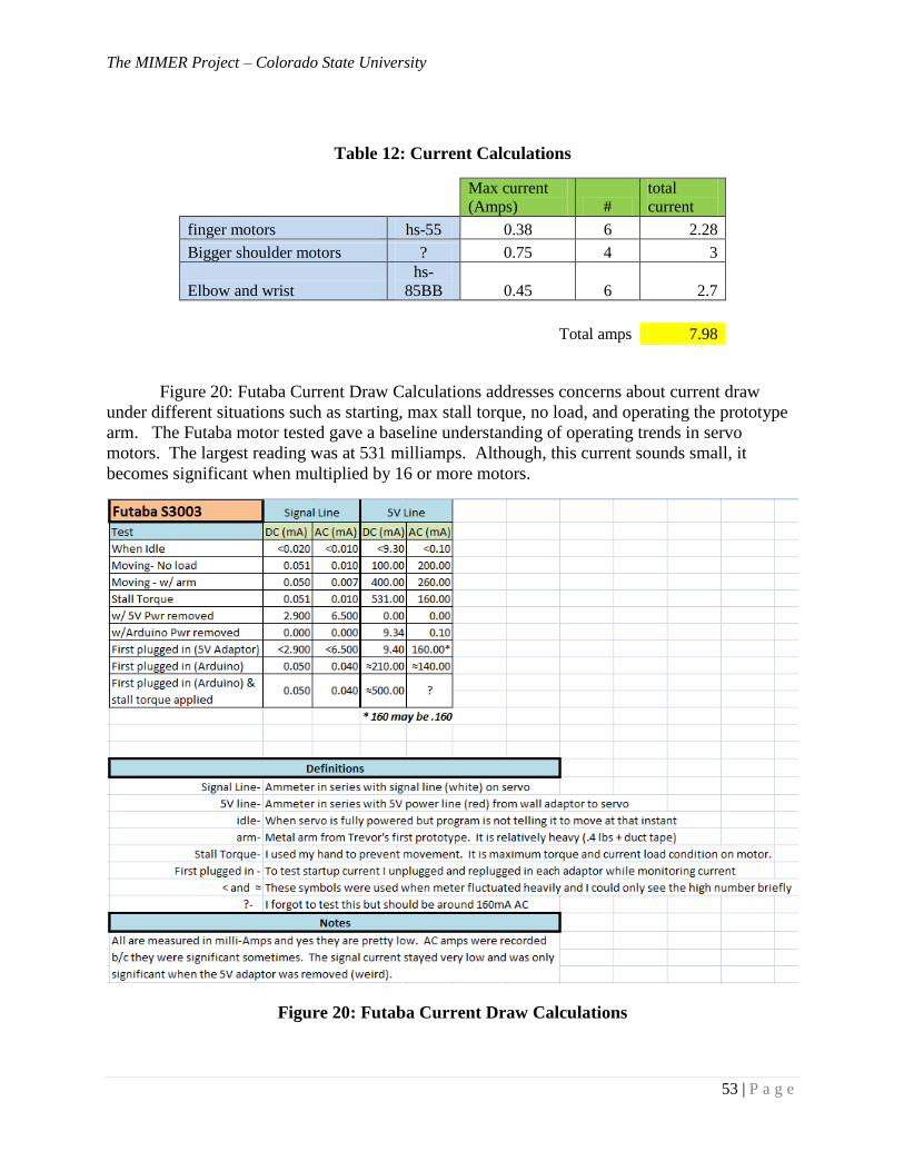
The MIMER Project – Colorado State University
53 | P a g e
Table 12: Current Calculations
Max current
(Amps) #
total
current
finger motors hs-55 0.38 6 2.28
Bigger shoulder motors ? 0.75 4 3
Elbow and wrist
hs-
85BB 0.45 6 2.7
Total amps 7.98
Figure 20: Futaba Current Draw Calculations addresses concerns about current draw
under different situations such as starting, max stall torque, no load, and operating the prototype
arm. The Futaba motor tested gave a baseline understanding of operating trends in servo
motors. The largest reading was at 531 milliamps. Although, this current sounds small, it
becomes significant when multiplied by 16 or more motors.
Figure 20: Futaba Current Draw Calculations
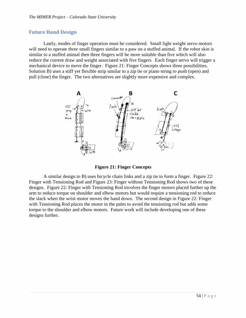
The MIMER Project – Colorado State University
54 | P a g e
Future Hand Design
Lastly, modes of finger operation must be considered. Small light weight servo motors
will need to operate three small fingers similar to a paw on a stuffed animal. If the robot skin is
similar to a stuffed animal then three fingers will be more suitable than five which will also
reduce the current draw and weight associated with five fingers. Each finger servo will trigger a
mechanical device to move the finger. Figure 21: Finger Concepts shows three possibilities.
Solution B) uses a stiff yet flexible strip similar to a zip tie or piano string to push (open) and
pull (close) the finger. The two alternatives are slightly more expensive and complex.
Figure 21: Finger Concepts
A similar design to B) uses bicycle chain links and a zip tie to form a finger. Figure 22:
Finger with Tensioning Rod and Figure 23: Finger without Tensioning Rod shows two of these
designs. Figure 22: Finger with Tensioning Rod involves the finger motors placed further up the
arm to reduce torque on shoulder and elbow motors but would require a tensioning rod to reduce
the slack when the wrist motor moves the hand down. The second design in Figure 22: Finger
with Tensioning Rod places the motor in the palm to avoid the tensioning rod but adds some
torque to the shoulder and elbow motors. Future work will include developing one of these
designs further.
A B C
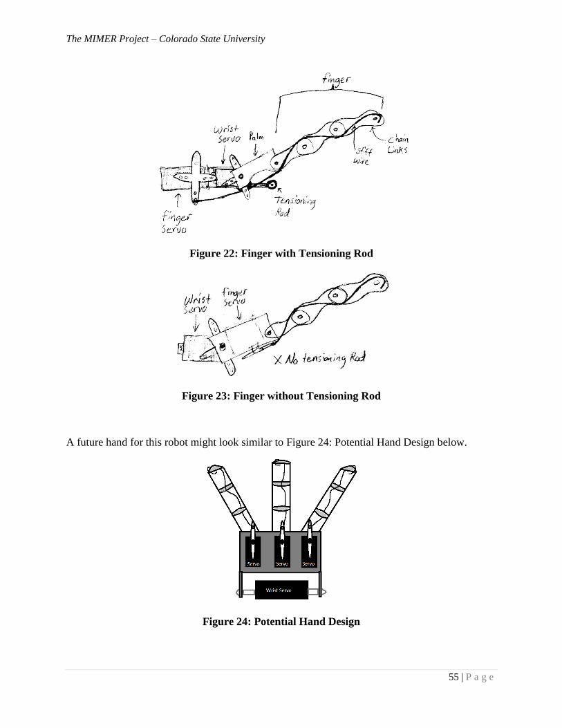
The MIMER Project – Colorado State University
55 | P a g e
Figure 22: Finger with Tensioning Rod
Figure 23: Finger without Tensioning Rod
A future hand for this robot might look similar to Figure 24: Potential Hand Design below.
Figure 24: Potential Hand Design
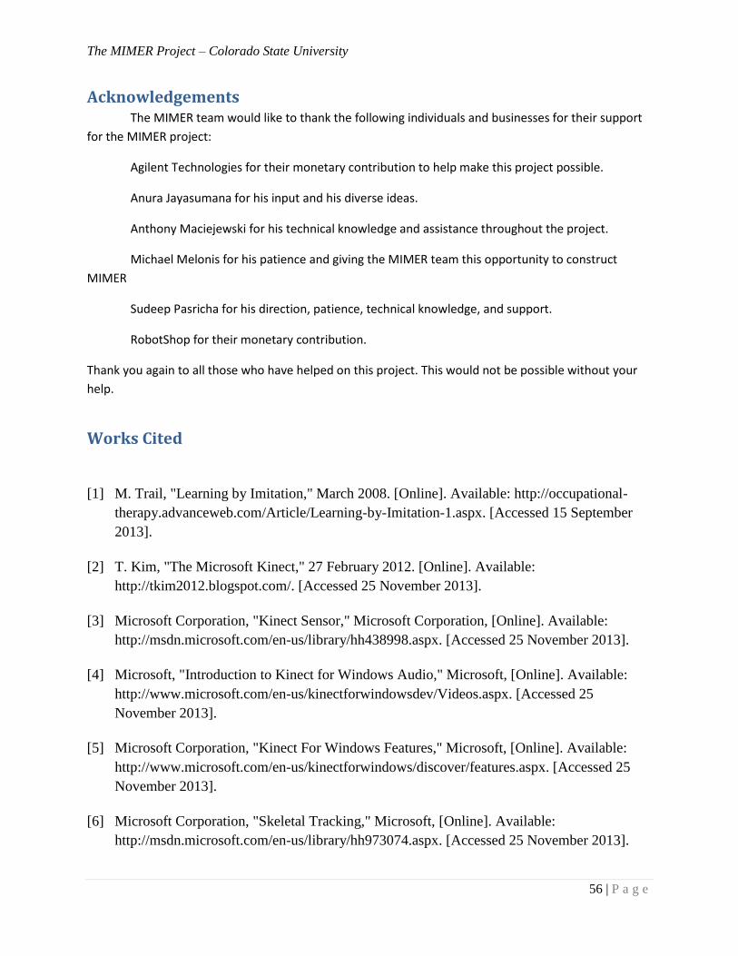
The MIMER Project – Colorado State University
56 | P a g e
Acknowledgements The MIMER team would like to thank the following individuals and businesses for their support
for the MIMER project:
Agilent Technologies for their monetary contribution to help make this project possible.
Anura Jayasumana for his input and his diverse ideas.
Anthony Maciejewski for his technical knowledge and assistance throughout the project.
Michael Melonis for his patience and giving the MIMER team this opportunity to construct
MIMER
Sudeep Pasricha for his direction, patience, technical knowledge, and support.
RobotShop for their monetary contribution.
Thank you again to all those who have helped on this project. This would not be possible without your
help.
Works Cited
[1] M. Trail, "Learning by Imitation," March 2008. [Online]. Available: http://occupational-
therapy.advanceweb.com/Article/Learning-by-Imitation-1.aspx. [Accessed 15 September
2013].
[2] T. Kim, "The Microsoft Kinect," 27 February 2012. [Online]. Available:
http://tkim2012.blogspot.com/. [Accessed 25 November 2013].
[3] Microsoft Corporation, "Kinect Sensor," Microsoft Corporation, [Online]. Available:
http://msdn.microsoft.com/en-us/library/hh438998.aspx. [Accessed 25 November 2013].
[4] Microsoft, "Introduction to Kinect for Windows Audio," Microsoft, [Online]. Available:
http://www.microsoft.com/en-us/kinectforwindowsdev/Videos.aspx. [Accessed 25
November 2013].
[5] Microsoft Corporation, "Kinect For Windows Features," Microsoft, [Online]. Available:
http://www.microsoft.com/en-us/kinectforwindows/discover/features.aspx. [Accessed 25
November 2013].
[6] Microsoft Corporation, "Skeletal Tracking," Microsoft, [Online]. Available:
http://msdn.microsoft.com/en-us/library/hh973074.aspx. [Accessed 25 November 2013].
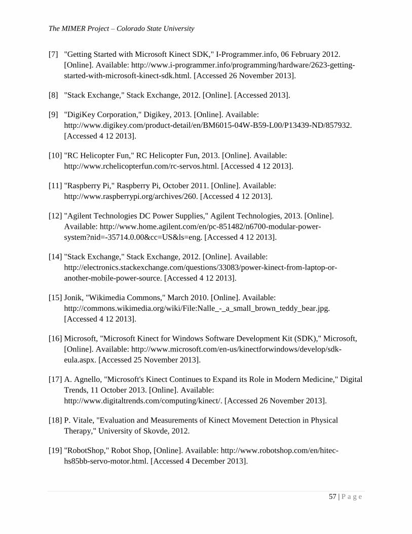
The MIMER Project – Colorado State University
57 | P a g e
[7] "Getting Started with Microsoft Kinect SDK," I-Programmer.info, 06 February 2012.
[Online]. Available: http://www.i-programmer.info/programming/hardware/2623-getting-
started-with-microsoft-kinect-sdk.html. [Accessed 26 November 2013].
[8] "Stack Exchange," Stack Exchange, 2012. [Online]. [Accessed 2013].
[9] "DigiKey Corporation," Digikey, 2013. [Online]. Available:
http://www.digikey.com/product-detail/en/BM6015-04W-B59-L00/P13439-ND/857932.
[Accessed 4 12 2013].
[10] "RC Helicopter Fun," RC Helicopter Fun, 2013. [Online]. Available:
http://www.rchelicopterfun.com/rc-servos.html. [Accessed 4 12 2013].
[11] "Raspberry Pi," Raspberry Pi, October 2011. [Online]. Available:
http://www.raspberrypi.org/archives/260. [Accessed 4 12 2013].
[12] "Agilent Technologies DC Power Supplies," Agilent Technologies, 2013. [Online].
Available: http://www.home.agilent.com/en/pc-851482/n6700-modular-power-
system?nid=-35714.0.00&cc=US&ls=eng. [Accessed 4 12 2013].
[14] "Stack Exchange," Stack Exchange, 2012. [Online]. Available:
http://electronics.stackexchange.com/questions/33083/power-kinect-from-laptop-or-
another-mobile-power-source. [Accessed 4 12 2013].
[15] Jonik, "Wikimedia Commons," March 2010. [Online]. Available:
http://commons.wikimedia.org/wiki/File:Nalle_-_a_small_brown_teddy_bear.jpg.
[Accessed 4 12 2013].
[16] Microsoft, "Microsoft Kinect for Windows Software Development Kit (SDK)," Microsoft,
[Online]. Available: http://www.microsoft.com/en-us/kinectforwindows/develop/sdk-
eula.aspx. [Accessed 25 November 2013].
[17] A. Agnello, "Microsoft's Kinect Continues to Expand its Role in Modern Medicine," Digital
Trends, 11 October 2013. [Online]. Available:
http://www.digitaltrends.com/computing/kinect/. [Accessed 26 November 2013].
[18] P. Vitale, "Evaluation and Measurements of Kinect Movement Detection in Physical
Therapy," University of Skovde, 2012.
[19] "RobotShop," Robot Shop, [Online]. Available: http://www.robotshop.com/en/hitec-
hs85bb-servo-motor.html. [Accessed 4 December 2013].
The MIMER Project – Colorado State University
58 | P a g e
[20] "RobotShop," RobotShop, [Online]. Available: http://www.robotshop.com/en/hitec-
hs645mg-servo-motor.html. [Accessed 4 December 2013].
[21] "RobotShop," RobotShop, [Online]. Available: http://www.robotshop.com/en/hitec-hs55-
servo-motor.html. [Accessed 4 December 2013].
[22] "RobotShop," RobotShop, [Online]. Available: http://www.robotshop.com/en/lynxmotion-
servo-bracket-asb-09.html. [Accessed 4 December 2013].
[23] "RobotShop," RobotShop, [Online]. Available: http://www.robotshop.com/en/lynxmotion-
hub-08-connector-hub.html. [Accessed 4 December 2013].
[24] "RobotShop," RobotShop, [Online]. Available: http://www.robotshop.com/en/lynxmotion-
humanoid-torso-a-bt-01.html. [Accessed 4 December 2013].
[25] WinBeta, "Developers getting Kinect for Windows v2 pre-release kits," WinBeta, 23
November 2013. [Online]. Available: http://www.winbeta.org/news/developers-getting-
kinect-windows-v2-pre-release-kits. [Accessed 25 November 2013].
[26] "RaspberryPi," RaspberryPi, [Online]. Available: http://www.raspberrypi.org/faqs.
[Accessed 25 November 2013].
[27] "RobotShop," RobotShop, [Online]. Available: http://www.robotshop.com/en/cytron-12v-
12rpm-166oz-in-spur-gearmotor.html. [Accessed 4 December 2013].
[28] "Furn Bedside Cabinets," Hill-Rom, [Online]. Available: http://www2.hill-
rom.com/medicraft/Furn_Bedside_Cabinets.htm. [Accessed 4 December 2013].
[29] S. Raiten, "Kinect - Getting Started - Become The Incredible Hulk," Code Project, 18 June
2011. [Online]. Available: http://www.codeproject.com/Articles/213034/Kinect-Getting-
Started-Become-The-Incredible-Hulk. [Accessed 25 November 2013].
Recommended


![[ , ] Autonomous Human Robot Interactive Skills](https://img.pdfslide.net/doc/110x75/577cc35f1a28aba71195d883/-autonomous-human-robot-interactive-skills.jpg)