CHEM 121L
General Chemistry Laboratories
Revision 3.3
The Structure of Solids
In this laboratory exercise we will examine the structure of crystalline solids that form cubic
lattice structures. We will do this by building models of representative solids that form
these structures. These solids will include Metallic, Covalent Network and Ionic solids.
Solids are generally the result of condensation of a gas or fusion of a liquid. We can divide
solids into two broad classes based on the orderliness of their particles. Crystalline Solids
generally have a well defined shape. Amorphous Solids have poorly defined shapes because
they lack extensive molecular-level packing. We will focus on the former types of solids.
Crystalline solids are subdivided into one of four major types:
Atomic or Molecular Solids
Here, discrete molecules, formed by covalent bonding of the constituent atoms, are held together by
intermolecular forces; London Dispersion Forces (LDF), Dipole-Dipole Interactions, or H-Bonding.
As an example, Methane, CH4, crystallizes as a Face-Centered Cubic solid (more on this later) in which
the molecules are held together by LDF interactions. (Recall, the C-H bond is non-polar and this
molecule has a symmetric tetrahedral shape. Both of these properties make the molecule non-polar.)
Crystal Structure of Methane
Metallic Solids
Metals are substances that exhibit luster, are malleable and ductile, and have high electrical and
thermal conductivities. Here, atoms of the metal are held together by Metallic Bonding. Because
metal atoms tend to have very few valence electrons, and low electronegativities, the atoms of the
metal collectively share their valence electrons. All the metal atoms pool their valence electrons into
an evenly distributed "sea" that "flows" between and around the metal ion cores (nucleus plus inner
electrons) and attracts them, thereby holding them together. Copper is an excellent example of a
metallic solid.

P a g e | 2
Ionic Solids
Here, cations and anions are held together by the electrical attraction of opposite charges. This
electrostatic attraction forms the basis of an Ionic Bond between the ions. The solid generally
consists of a large lattice in which no distinct “molecules” exist. A typical example is Common Salt,
or NaCl. The cations (Na+) and anions (Cl
-) crystallize as interpenetrating Face-Centered Cubic
(more on this later) lattices.
Crystal of NaCl (Green = Cl
- and Blue = Na
+)
(http://www.teachbuzz.com/lessons/earths-minerals)
Network Covalent Solids
Like an ionic solid, network covalent solids have no discrete molecules. Instead, every atom in the
solid is held together by a covalent bond; forming a large network of these bonds. Carbon, as either
diamond or graphite, produces a network covalent solid.
Lewis Structure of Carbon
We now turn to the nature of the arrangement of the atoms, or molecules, in a crystal of
these types of solids. If we could see the particles within the crystal, we would see them
packed tightly together in an orderly three-dimensional array called the crystal lattice.
Further, we would notice a periodicity to the array; the underlying unit of periodicity is
referred to as the unit cell. The structure of the unit cell will manifest itself in the

P a g e | 3
macroscopic crystalline structure of the compound. For instance, Common Salt, as was seen
above, forms a cubic unit cell. This is readily apparent in the structure of its crystals.
Crystals of Common Salt
(http://upload.wikimedia.org/wikipedia/commons/2/
22/Sodiumchloride_crystal_01.jpg)
There are 7 unique unit-cell shapes (cubic, hexagonal, tetragonal, orthorhombic,
rhombohedral, monoclinic, triclinic) that can fill all 3-D space. These are the 7 Crystal
Systems. Although there are only seven different crystal shapes, there are 14 different
crystalline lattices. For instance, the cubic shape can form Simple Cubic (sc), Body-
Centered Cubic (bcc) and Face-Centered Cubic lattices (fcc).
We will focus on these cubic crystal lattice structures.
The Simple Cubic structure occurs when spheres forming a square-packing layer are placed
directly on top of one another. This structure is relatively rare. Body-Centered Cubic
arrangements result when a second square-packing layer is offset from the first such that it
is nested in the spaces in the first:

P a g e | 4
two layers of particles forming a bc lattice (Teaching General Chemistry: A Materials Science Companion
by Arthur B. Ellis et al)
layer of particles forming a sc lattice
The Face-Centered Cubic lattice is formed from close packing of spheres:
three layers of particles forming a fcc lattice (Teaching General Chemistry: A Materials Science Companion by Arthur B. Ellis et al)
Elemental metals form the simplest unit cells because each sphere in these diagrams
corresponds to an atom in the metal. The crystal structures of many of the metallic elements
is provided in the Appendix below. It should be noted the majority form Face-Centered
Cubic and Hexagonal Close Packing structures. These two structures, which are slight
variations on each other, represent the most densely packed arrangement of spheres.
Two parameters of atomic interest concerning the arrangement of the particles within the
unit cell are the Coordination Number and the number of atoms/particles contained in the
Cell. The first, the coordination number, is defined as the number of nearest neighbor
particles. The second is simply a count of the number of particles that are part of a given
unit cell. For an illustration, consider a simple cubic unit cell. First, notice that any given
sphere within the Cell will have six nearest neighbors; two are not shown. Hence, the
coordination number for this structure is six. Second, each particle is shared by several
adjacent unit cells such that only 1/8 of each particle is contained within the pictured Cell.

P a g e | 5
Hence, the number of particles contained within this Cell is one. These parameters are of
particular importance when considering the stoichiometry of ions in an ionic solid.
Ionic solids are an interesting case. Because there are two types of "particles" within the
solid (cations and anions), we can frequently think of a unit cell for the anion as
interpenetrating a unit cell for the cation; or, vice-versa. For example, NaCl crystallizes
with the Na+ ions in a Face-Centered Cubic unit and with the Cl
- ions also Face-Centered
Cubic. (It is not always true that the two unit cells are identical.)
As an alternative, we can focus on one of these unit cells, say the cation's, and view the
anions as filling holes within the cell. The reverse view will also hold. In either case,
within a given unit cell, the number of cations relative to the number of anions must
conform to that given by the chemical formula; 1 Na+ to 1 Cl
- in the case of NaCl.
The Cubic structures exhibit three common hole types. The Simple Cubic unit cell contains
a Cubic Hole, whereas the Face-Centered Cubic cell contains both Octahedral and
Tetrahedral holes:
P a g e | 6
(Cubic Hole) (Octahedral Hole) (Tetrahedral Hole)
(Teaching General Chemistry: A Materials Science Companion by Arthur B. Ellis et al)
Although it may not be readily obvious (you will have a chance to view this in more detail
in the laboratory), the Face-Centered Cubic unit cell for the Na+ ions in the NaCl crystal
contains Cl- ions in Octahedral holes. The reverse also happens to be true; although, again,
this is not always the case.
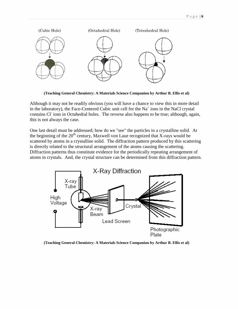
One last detail must be addressed; how do we "see" the particles in a crystalline solid. At
the beginning of the 20th
century, Maxwell von Laue recognized that X-rays would be
scattered by atoms in a crystalline solid. The diffraction pattern produced by this scattering
is directly related to the structural arrangement of the atoms causing the scattering.
Diffraction patterns thus constitute evidence for the periodically repeating arrangement of
atoms in crystals. And, the crystal structure can be determined from this diffraction pattern.
(Teaching General Chemistry: A Materials Science Companion by Arthur B. Ellis et al)

P a g e | 7
Sample Diffraction Pattern for NaCl
The X-ray diffraction experiment has been used to establish the structures of many different
crystalline solids. Additionally, it can be used on much larger biomolecules, such as
proteins or nucleic acids, and is considered the definitive method for structure determination
of these compounds.
In this laboratory, we will examine the structure of various solids. We will build models of
various metallic, covalent network and ionic solids and examine the structures they form.

P a g e | 8
Pre-Lab Questions
1. Polonium, the largest member of Group 6A, is a rare radioactive metal that is the only
element with a crystal structure based on the Simple Cubic unit cell. The density of
Polonium is 9.142 g/cm3. Calculate an atomic radius for the Polonium atom based on
this data.
2. Close-packing of spheres involves arranging this spheres three dimensionally such
they take up the greatest percentage of 3-Dimensional space. The “efficiency” of
packing involves the percentage of space occupied.
Consider two dimensional packing of circles. Two possible arrangements are
provided below:
Calculate the packing efficiency in each case. Hint: For the hexagonal case, consider
the following geometry:
(Teaching General Chemistry: A Materials Science Companion by
Arthur B. Ellis et al)
3. To state the obvious, the symmetry of a solid’s crystal
faces is determined by the nature of the crystal’s lattice
structure. In the case of the Pyrite (FeS2) pictured
here, the face-centered-cubic unit cell has manifested
itself as cubic crystals.
We will deal with the possible crystal shapes for Pyrite
in the Addendum exercise below. Here it is merely our
desire to observe some of the shapes of the crystalline

P a g e | 9
solids whose unit cell models we will be constructing. As part of your Pre-Lab
assignment, you should go to the Mineral Museum on campus and examine the
crystals formed by three of our solids. For each crystal, you should note:
1. Crystal Shape
2. Origin of the Mineral
3. Sketch a Portion or Take a Picture of the Mineral
All of the mineral’s you are to examine can be found in the "Europe & Africa"
display case in the main Hall. (Second case on the left as you enter the main
Hall.) Each is identified with a numbered identifier. The minerals you should
examine are:
Halite (NaCl) #4450
Halite (NaCl) #16644
Fluorite (CaF2) #276
Fluorite (CaF2) #274
Fluorite (CaF2) #18671
Fluorite (CaF2) #15825
Sphalerite (ZnS) #15379
Pyrite (FeS2) #11-01
Pyrite (FeS2) #15378
Pyrite (FeS2) #9550
More information concerning crystal symmetry can be found at:
http://www.tulane.edu/~sanelson/eens211/crystalmorphology&symmetry.htm
P a g e | 10
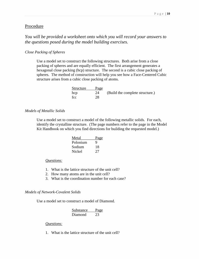
Procedure
You will be provided a worksheet onto which you will record your answers to
the questions posed during the model building exercises.
Close Packing of Spheres
Use a model set to construct the following structures. Both arise from a close
packing of spheres and are equally efficient. The first arrangement generates a
hexagonal close packing (hcp) structure. The second is a cubic close packing of
spheres. The method of construction will help you see how a Face-Centered Cubic
structure arises from a cubic close packing of atoms.
Structure Page
hcp 24 (Build the complete structure.)
fcc 28
Models of Metallic Solids
Use a model set to construct a model of the following metallic solids. For each,
identify the crystalline structure. (The page numbers refer to the page in the Model
Kit Handbook on which you find directions for building the requested model.)
Metal Page
Polonium 9
Sodium 18
Nickel 27
Questions:
1. What is the lattice structure of the unit cell?
2. How many atoms are in the unit cell?
3. What is the coordination number for each case?
Models of Network-Covalent Solids
Use a model set to construct a model of Diamond.
Substance Page
Diamond 23
Questions:
1. What is the lattice structure of the unit cell?

P a g e | 11
2. What is the geometric structure about each Carbon atom?
3. What type of hole is filled in the unit cell, and percentage of these holes are
filled?
4. What is the coordination number of the coordination number of each
Carbon?
Models of Ionic Solids
Use a model set to construct a model of the following ionic solids. For each, identify
the crystalline structure and the nature of the hole being filled.
Compound Page
CsCl 11 and 12
NaCl 33
ZnS* 51
CaF2 14 and 16
Na2O 59
TiO2* 74 (tetragonal; or, distorted cubic)
Questions:
1. Which color sphere represents the cation and which the anion? (Use the
ionic radii reported in the Appendix to decide which color corresponds to
which ion.)
2. What is the lattice structure of the cation? What is the lattice structure of
the anion?
3. What type of hole is filled by the cation? What percentage of these holes is
filled? What type of hole is filled by the anion? What percentage of these
holes are filled?
4. For the cation unit cell, how many cations and how many anions occupy
the unit cell? Do the same for the anion unit cell.
5. What is the coordination number of the cation? The anion?
* Not all of these questions will be answered for ZnS and TiO2.

P a g e | 12
Appendix - Crystal Structures of the Metallic Elements
From: Teaching General Chemistry: A Materials Science Companion by Arthur B. Ellis et al

P a g e | 13
Appendix - Ionic Radii
All values reported in picometers.
Group 1A Group 2A Group 1B Group 2B Group 3A Group 4A Group 6A Group 7A
H-
208
Li+ Be
2+ B
3+ C
4+ O
2- F
-
60 31 20 15 140 136
Na+ Mg
2+ Al
3+ Si
4+ S
2- Cl
-
95 65 50 41 184 181
K+ Ca
2+ Cu
+ Zn
2+ Ga
3+ Ge
4+ Se
2- Br
-
133 99 96 74 62 53 198 195
Rb+ Sr
2+ Ag
+ Cd
2+ In
3+ Sn
4+ Te
2- I
-
148 113 126 97 86 71 221 216
Cs+ Ba
2+ Au
+ Hg
2+ Tl
3+ Pb
4+
169 135 137 110 95 84
Tl+ Pb
2+
140 121
... there are probably as many different ways of estimating ion radii as there are ways of
estimating atom and ion electronegativities. One of the ways to arrive at a set of io radii
is the following. Many compounds are known for which variation of the cation has
essentially no effect on the cation-anion internuclear distance. This phenomena is
interpreted to mean that for such compounds the cations just fit into or are somewhat
smaller than the holes they occupy in the anion lattices. In other words, the distance
between the anion nucleus and the hole center is fixed by the fact that the anions are just
in contact with one another. According to this interpretation, the anion rdius is simply
half of the anion-anion internuclear distance. In this vein, “absolute” radii can be
established for anions, and these in turn can be used to determine the cation radii in salts
of those same anions where the cation-anion distance is not independent of the cation.
By systematically considering various salts, one expands a list of cation and anion radii.
The procedure inevitably produces some discrepancies, which have been studied from
several points of view. Probably the widely accepted ion radii are those of Pauling, who
introduced corrections for the greater internal compression forces in crystals with ions of
high charge. These corrected adii are termed rystal radii, and some of them are
presented [above]. A word of caution is in order regarding these values. Their absolute
magnitudes are of questionable meaning; they have their greatest use in the operational
sense of compaing relative ion sizes and intermolecular distances in crystals.
An Introduction to Inorganic Chemistry
by Keith F. Purcell and John C. Kotz

P a g e | 14
Addendum
Crystal Shapes
As was briefly mentioned above, the crystalline form a substance adopts will be a direct
manifestation of its underlying internal structure; i.e., the structure of its unit cell. In this
observational exercise, you will examine the crystal structures adopted by Pyrite, FeS2. The
unit cell for this material is composed of a face-centered cubic lattice, adopted by the Iron
(blue in picture below), with embedded Sulfide Ions (yellow in picture below).
(http://en.wikipedia.org/wiki/File:FeS2structure.png)
This unit cell can manifest itself as a cubic crystal shape via a simple stacking of the
underlying cubes.
http://en.wikipedia.org/wiki/File:Pyrite_from_Ampliaci%C3%B3n_a_Victoria_Mine,
_Navaj%C3%BAn,_La_Rioja,_Spain_2.jpg

P a g e | 15
But, Pyrite can also adopt other crystal shapes. These shapes are a result of different
stacking arrangements and will occur naturally when the crystal forms under different
environmental conditions. In this exercise you will examine the common additional shapes
of Pyrite crystals and correlate them with differences in the stacking of the unit cells.
Procedure
1. Examine the Pyrite crystals on display. Sketch each of the three crystal shapes
exhibited by Pyrite.
2. Correlate each shape with the appropriate stacking arrangement.
3. Examine the crystal shapes for the Common Alum and Chrome Alum. These solids
also have cubic unit cells.
Recommended