ALERT workshop, 16th September 2016, Trieste, ItalyMarek Grabski
1
16th September 2016
Trieste, Italy
MAX IV 3 GeV ring vacuum system
Advanced Low Emittance Rings Technology (ALERT)2016 Workshop
On behalf of the vacuum team
Marek Grabski, Max IV laboratory
ALERT workshop, 16th September 2016, Trieste, ItalyMarek Grabski
2
Contents
• Machine and vacuum system layout,
• NEG-coating R&D at CERN,
• Installation procedure,
• Vacuum commisioning status.

ALERT workshop, 16th September 2016, Trieste, ItalyMarek Grabski
3
MAX IV layout
https://www.maxlab.lu.se/maxiv
3 GeV ring (528 m)
Linac (300 m)Short pulse
facility
1.5 GeV ring (96 m)Conventional
design
Small aperture,all NEG-coated
Max IV - Synchrotron light source facility in Lund, Sweden.
Commissioning started:
August 2015Commissioning started:
September 2016

ALERT workshop, 16th September 2016, Trieste, ItalyMarek Grabski
4
3 GeV ring layout
100 MHz RF cavities
Landau cavities
InjectionEmittance measurement
Circumference 528 m, 20 achromats, 19 straight sections for IDs
2 In vacuum undulators (2 m long)
• NanoMAX IVU18
• BioMAX IVU18
2 EPU (4 m long, min gap 11 mm)
• VERITAS EPU48
• HIPPIE EPU53
1 In vac. Wiggler (2.4 m long)
• BALDER IVW50
Installed Insertion Devices:
Legend:
• Dk: Dipole kicker (S1)
• Mk: Multipole kicker (L)
• LK: Longitudinal kicker (S2)
• VP: Vertical pinger (S2)
L=long straight, S=short straight,

ALERT workshop, 16th September 2016, Trieste, ItalyMarek Grabski
5
U2, VC4
Min. clearance with the iron 0.5 mm, min. clearance with the coils 2 mm.
Ø22
(ID)
Dipole
3 GeV magnet layoutOne achromat
Beam direction
Photon beam
Corrector25mm
Chamber ID 22mm
Magnet apertures Ø25mm
Sextupole
Ø25
- Total length ~26 m, - 4.5 m straight section (L)

ALERT workshop, 16th September 2016, Trieste, ItalyMarek Grabski
6
Standard vacuum chamber geometryOne achromat
Beam direction
VC5
Distributed cooling
Ribs
Cooling for corrector
Cooling for corrector
Welded bellows
Welded bellows
Chamber body
Material: OFS copper
Inside diameter: 22 mm, Total length: 2.5 m,
Bent part Arc length: 1 m, Bending angle: 30, Bending radius: 19 m.
NEG-coated.
Bent part
VC5 chamber

ALERT workshop, 16th September 2016, Trieste, ItalyMarek Grabski
7
Vacuum achromat layout
Penning gauge (S2)
Extractor gauge (S1)
In each achromat:
10 BPMs,
3 pumping ports (with ion pumps) and 1 pump in FE,
1 crotch absorber,
3 gate valves.
One achromat
Beam direction
VC1VC2
VC3
VC4VC5
VC6
VC7
VC8VC9
VC10
One achromatLength: ~26m
ALERT workshop, 16th September 2016, Trieste, ItalyMarek Grabski
8
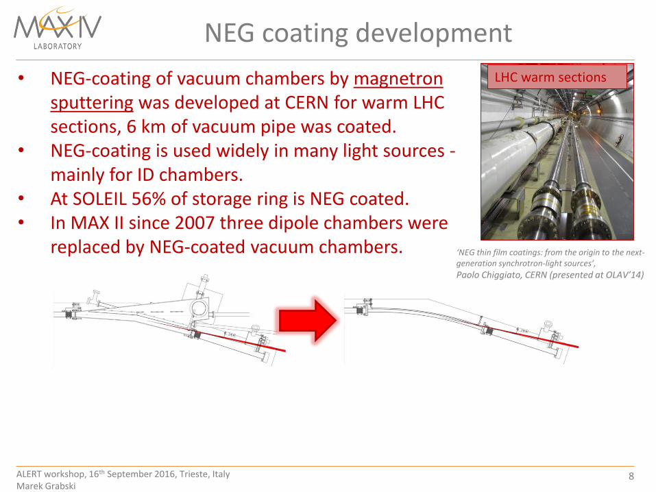
NEG coating development
• NEG-coating of vacuum chambers by magnetron sputtering was developed at CERN for warm LHC sections, 6 km of vacuum pipe was coated.
• NEG-coating is used widely in many light sources -mainly for ID chambers.
• At SOLEIL 56% of storage ring is NEG coated. • In MAX II since 2007 three dipole chambers were
replaced by NEG-coated vacuum chambers.
LHC warm sections
‘NEG thin film coatings: from the origin to the next-generation synchrotron-light sources’,
Paolo Chiggiato, CERN (presented at OLAV’14)

ALERT workshop, 16th September 2016, Trieste, ItalyMarek Grabski
9
NEG-coating R&D at CERN
1. Define and perform initial surface treatment of OFS copper substrate.
2. Validate compatibility of NEG-coating (adhesion, thickness, activation
behavior):
a). on etched OFS copper.
b). on wire-eroded surfaces and used brazing alloys.
To validate the coating feasibility 3 main stages of NEG (Ti, Zr, V) coating
validation by magnetron sputtering in collaboration with CERN were undertaken.
(R&D duration ~2 years).
3. NEG-coating validation of compact vacuum chamber geometries:
a). Coating and testing of small diameter, bent tubes.
b). Establish coating procedure/technology and coat chambers
of complex geometry.

ALERT workshop, 16th September 2016, Trieste, ItalyMarek Grabski
10
NEG-coating series production
1. Standard bent vacuum chambers (VC4) - 1.50 and 30 bends,
2. Straight vacuum (VC10) chambers,
3. Special vacuum chambers.
30
2.8 m (VC4)
2 m (VC10B)
Electron beam
Photon beamVC2
BPM
17.2 mm
Ø22
Ø22 mm
One achromatBeam direction
3 GeV - 1 achromat (~26m)
VC4VC2
Industry (70% length wise)
Collaboration with ESRF (15%)
Collaboration with CERN (15%)
Main vacuum chamber types:
VC10
Photon beam

ALERT workshop, 16th September 2016, Trieste, ItalyMarek Grabski
11
Installation procedure
Installation of NEG-coated ring
Ring installation was tested and
rehearsed by installing and activating
1 mockup achromat in summer 2014.
Actual installation started in
November 2014, ended June 2015
ALERT workshop, 16th September 2016, Trieste, ItalyMarek Grabski
12
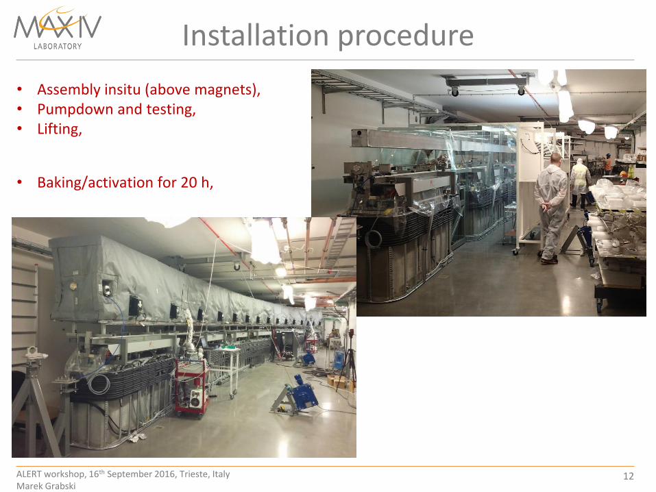
Installation procedure
• Assembly insitu (above magnets), • Pumpdown and testing, • Lifting,
• Baking/activation for 20 h,

ALERT workshop, 16th September 2016, Trieste, ItalyMarek Grabski
13
Installation procedure
• Lowering to the bottom magnet half, • Installation of final equipment (supports,
BPM cables),
• closing magnet blocks.

ALERT workshop, 16th September 2016, Trieste, ItalyMarek Grabski
14
Coating non-conformitiesAll the chambers were inspected at site before installtion.
Peeling-off at RF fingers and Cu endpiece
Observed peeling-off:At RF fingers Cu-Be insert and Cu end piece. RF fingers and Cu end were not shielded properly during coating. Solution: new pieces ordered and replaced (without coating).
Uncoated areas:Few cm^2 uncoated, in complex chambers.
Uncoated areas
Peeling-offPeeling-off at the edge
of stainless VC. Chamber not aproved for
installation.
Severe peeling-off

ALERT workshop, 16th September 2016, Trieste, ItalyMarek Grabski
15
Commissioning progress
Commissioning started in August 2015
0
20
40
60
80
100
120
1-A
ug-
20
15
31
-Au
g-2
01
5
1-O
ct-2
01
5
31
-Oct
-20
15
1-D
ec-2
01
5
31
-Dec
-20
15
31
-Jan
-20
16
1-M
ar-2
01
6
1-A
pr-
20
16
1-M
ay-2
01
6
1-J
un
-20
16
1-J
ul-
20
16
1-A
ug-
20
16
Do
se [
Ah
]
Date
Accumulated beam dose
reached: 112 Ah.
March 2016 shutdown:
- 2 in-vacuum undulators,
August 2016 shutdown:
- 2 EPU chambers (8x36mm),
- In-vacum wiggler.
Average base pressure:
Gauges 2e-10 mbar,
Ion pumps in 8e-11 mbar range.
2nd shutdown
1st shutdown

ALERT workshop, 16th September 2016, Trieste, ItalyMarek Grabski
16
Pressure vs beam current, dose
Beam direction
1E-10
3E-10
5E-10
7E-10
9E-10
1E-09
1E-09
2E-09
0
20
40
60
80
10
0
12
0
14
0
16
0
18
0
20
0
P av[m
bar
]
I [mA]
@dose=16 Ah
@dose=95 Ah
Pressures at dose 16 Ah and 95 Ah, during beam ramp up.
(presure recorded by extractor gauge at not NEG coated crotch
absorber in S1)

ALERT workshop, 16th September 2016, Trieste, ItalyMarek Grabski
17
Pressure in one achromat vs beam current
Beam direction
Pressures at dose 95 Ah, during beam ramp up, recorded at different positions along achromat (L, S1, S2)
1E-11
1E-10
1E-09
1E-08
1E-07
0
20
40
60
80
10
0
12
0
14
0
16
0
18
0
20
0
P av [m
bar
]
Beam Current [mA]
Legend:• Pressure at S1 (ion pump)• Pressure at S1 (extractor gauge)• Pressure at S2 (penning gauge)• Pressure at S2 (ion pump) • Pressure at L (ion pump)
* Pressure at L (Ion pump) probably due to electric effect

ALERT workshop, 16th September 2016, Trieste, ItalyMarek Grabski
18
Pressure vs beam current, dose
Beam direction
1E-12
1E-11
1E-10
1E-09
0.1 1 10 100 1000
No
mra
lized
aver
age
pre
ssu
rePa
v/I [
mb
ar/m
A]
Accumulated Dose [A∙h]
Y=(3.08e-10)*x^(-0.68)
Y=(1.64e-10)*x^(-0.75)
Normalized average pressure vs beam dose,
recorded in S1 uncoated crotch absorber, and S2 NEG-coated
Legend:• Pressure at S1
(extractor gauge)• Pressure at S2
(penning gauge)

ALERT workshop, 16th September 2016, Trieste, ItalyMarek Grabski
19
Lifetime evolution
1
10
100
1000
10000
0.1 1 10 100 1000
I∙τ
[mA∙h
]
Dose [A∙h]
Normalized lifetime vs accumulated doseI∙τ [mA∙h] vs Dose [Ah]
Beam lifetime up to 6 Ah,
Maximum stored beam
current 180 mA
ALERT workshop, 16th September 2016, Trieste, ItalyMarek Grabski
20
H2 (2)85.33%
He (4)0.12%
C (12)0.78%
(14)0.33%
(15)1.17%
CH4 (16)2.16%
OH (17)0.05%
H2O (18)0.10%
F (19)0.08%
CO (28)9.39% O2 (32)
0.01%
Cl (35)0.03%
Cl (36)0.00%
Ar (40)0.01%
CO2 (44)0.42%
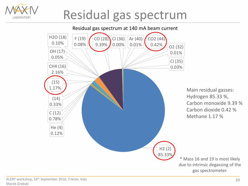
Residual gas spectrumResidual gas spectrum at 140 mA beam current
* Mass 16 and 19 is most likely due to intrinsic degassing of the
gas spectrometer.
Main residual gasses:Hydrogen 85.33 %, Carbon monoxide 9.39 %Carbon dioxide 0.42 %Methane 1.17 %

ALERT workshop, 16th September 2016, Trieste, ItalyMarek Grabski
21
Scraper measurementsMean lifetime vs vertical scraper distance from the beam center
(Done at beam dose 40 Ah)Total average pressure along the beam path
(contribution from all gasses based on the RGA spectra)
*Scraper measurements and calculations done by Jens Sundberg, Thanks!
At 50 mA:P_Torr = 3.3e-09 torrT_elastic= 104.69 hT_inelastic= 88.47 hT_Touschek= 16.62 h
y = 0.0363x + 1.5052R² = 0.9849
0
1
2
3
4
5
6
0 20 40 60 80 100
Pre
ssu
re [
e-9
To
rr]
Beam current [mA]
Scraper position from beam center, y (mm)
Mean
lif
eti
me, T
(h
)

ALERT workshop, 16th September 2016, Trieste, ItalyMarek Grabski
22
Problems
• RF cavity (S2) venting due to broken high power feedthrough
during conditioining (with closed valves). Now cavity is removed
from the ring and dummy chamber placed as could not be run with
high power anymore. Now awaits conditioning outside the ring.
Electron beam
Photon beam
Hot spot
• Hot spots in proximity of crotch absorber (S1), mis-positioning of
the crotch chamber,

ALERT workshop, 16th September 2016, Trieste, ItalyMarek Grabski
23
Future plans and development
Development needed:
• Coating of 8 mm aperture, long, bend chambers,
• Effective thin layer in-situ baking system without the need of removing the
vacuum chamber from the final location for re-activation,
• Handling of flexible delicate small vacuum pipes,
• Study new materials possible for chamber manufacturing,
• New methods of manufacturing (electroforming).
Preliminary Studies Towards a Diffraction-Limited Storage Ring- Pedro F. Tavares, September 2014
Vacuum system constraints:
• Vacuum chamber outer diameter 10 mm,
• Compact vacuum system design,
• Very low impedance flange/bellow
assemblies,
• Distributed pumping.
ALERT workshop, 16th September 2016, Trieste, ItalyMarek Grabski
24
Thank you for your attention
Acknowledgments:
Jonny Ahlbäck, Eshraq Al-Dmour, Michael Gilg, Pedro F. Tavares (MAX IV),
CERN, PKAB, ALBA, ESRF, BINP, Solaris and MAX IV staff
Recommended