TOSHIBA OPC UA Data Access Client Instruction Manual
6F8C1593

First Edition 13th January. 2016 The material in this manual may be revised without notice.
Copy right 2016 by Toshiba Corporation. All rights reserved. No part of this manual may be reproduced in any form without permission.
Introduction
i
Safety Precautions The instruction manual and the labels affixed to the products or equipment give important information for using products safely. It helps prevent damage to properties and hazard to people who use them or work with them. Make yourself familiar with the signal words and signs in this page, then read the safety precautions that follow and always follow the instructions to avoid hazards. Explanation of signal words Signal word is a word that designates a degree or level of hazard seriousness. The words WARNING and CAUTION are used for the products.
WARNING Indicates a potentially hazardous situation which could result in death or serious injury, if you do not follow the instructions.
CAUTION Indicates a potentially hazardous situation which may result in minor or moderate injury and/or property damage, if you do not follow the instructions.
Hazard alert shapes and symbols Following shapes and symbols are used in the safety precaution labels affixed to the products and in other places including operation manuals for giving safety instructions.
Filled circle means "Mandatory Action" or "Do as indicated." Required action is shown in the circle or described near the circle.
Circle band with a diagonal slash means "Prohibition" or " You must not do." Prohibited action is shown in the circle or described near the circle.
Triangle means "Hazard Alerting" or "Be alert against hazard." The kind of hazard is shown in the triangle or described near the triangle.
Exclamation point with a triangle is a safety alert symbol which indicates a potential hazard. It is used with a Signal Word.
Square or rectangle means "Information Messages" or "Notice."
Important precautions for system operation System fault or data loss may occur in the event of power outage whether it is external or internal of the system. Take precautions in advance to protect the system in order to prevent such event to take place. Also back up your data regularly to minimize the possible damage by loss of data as a result of such event. Confirmation of product safety label Confirm that product safety labels are put on the front panel of the power supply module. If the label is lost or soiled, inform TOSHIBA Corporation.
Introduction
ii
Introduction This manual explains how to use OPC UA (Unified Architecture) Client for testing TOSHIBA OPC UA Server. First, read "Safety Precautions" carefully to use this device safely and correctly. After you read this manual, keep it in a place where you can find it easily when you need it.
Composition of This Manual This manual is composed of the following chapters. Chapter 1 Outline of TOSHIBA OPC UA Data Access Client This explains the functions and composition of the TOSHIBA OPC UA Data Access Client. Chapter 2 Setting-Up TOSHIBA OPC UA Data Access Client This explains how to install, reinstall, uninstall and update the TOSHIBA OPC UA Data Access Client. Chapter 3 How to set the environments for TOSHIBA OPC UA Data Access Client This explains how to set the environments that TOSHIBA OPC UA Data Access Client. works with. Chapter 4 Specification for TOSHIBA OPC UA Data Access Client This explains how to launch TOSHIBA OPC UA Data Access Client. and its functionalities.
Microsoft and Windows are trademarks of US Microsoft Corporation registered in U.S.A. and other countries. Other company names and product names described in this manual are the trademarks and registered trademarks of the respective companies.
Introduction
iii
Conventions used in this manual
Other than safety precaution items, the following symbols are used to explain items that need your attention. Important: Explains items required to use the product correctly. Tip: Introduces referential matters to help you understand the main text. Reference: Documents you should refer to help you understand the main text. → Indicates reference locations of this manual or other manuals.
Prohibition of copying This OPC server is protected by Copyright. This OPC server can be installed in only one computer. When it is necessary to install OPC server in another computer, please buy the OPC server software newly.
Contents
iv
Contents
Safety Precautions i
Introduction iii 1. Outline 1
1.1. OPC UA 1 1.2. TOSHIBA OPC UA DataAccess Client 2
2. Setting-Up 3 2.1. Preparation 3 2.2. Installation 3 2.3. Repair 5 2.4. Uninstallation 7
3. How to set the environments 8 3.1. Windows Firewall 8
4. Specification 15 4.1 Launch TOSHIBA OPC UA Client 15 4.2 Overview of functionalities 16 4.3 [Server] menu 18 4.4 [Attributes] menu 23 4.5 [Monitored Items] menu 25 4.6 [Help] menu 28 4.7 [Browse] menu 29 4.8 [Monitor] menu 34
1. Outline
1
1. Outline This chapter describes the outline of OPC UA , and the movement environment and the construction of TOSHIBA OPC UA DataAccess Client.
1.1. OPC UA OPC-UA (UA for Unified Architecture) is the next generation OPC specification.
OPC is open connectivity in industrial automation and the enterprise systems that support industry.
The OPC standard for process control and automation has achieved wide adoption throughout industry. This is actually a family of standards and is based on Microsoft COM/DCOM.
However, in today's manufacturing industry, the times of the partial optimization have been over, and the action to the whole optimization started, and the cooperation between servers became essential from the PLC of the plant floor to an enterprise server. The COM technology for which an implementation technology depended on a platform came to have difficulty in showing the ability because the company system was often constructed on various platforms.
Then OPC UA provides unified address space and service model to solve these problems , and suggests the systems construction architecture , which does not depend on a platform for the a great variety of formats such as XML documents and multi-transport (TCP and SOAP Web Service).
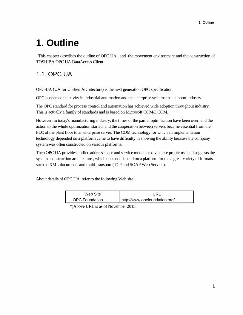
About details of OPC UA, refer to the following Web site.
Web Site URL OPC Foundation http://www.opcfoundation.org/
*)Above URL is as of November 2015.
1. Outline
2
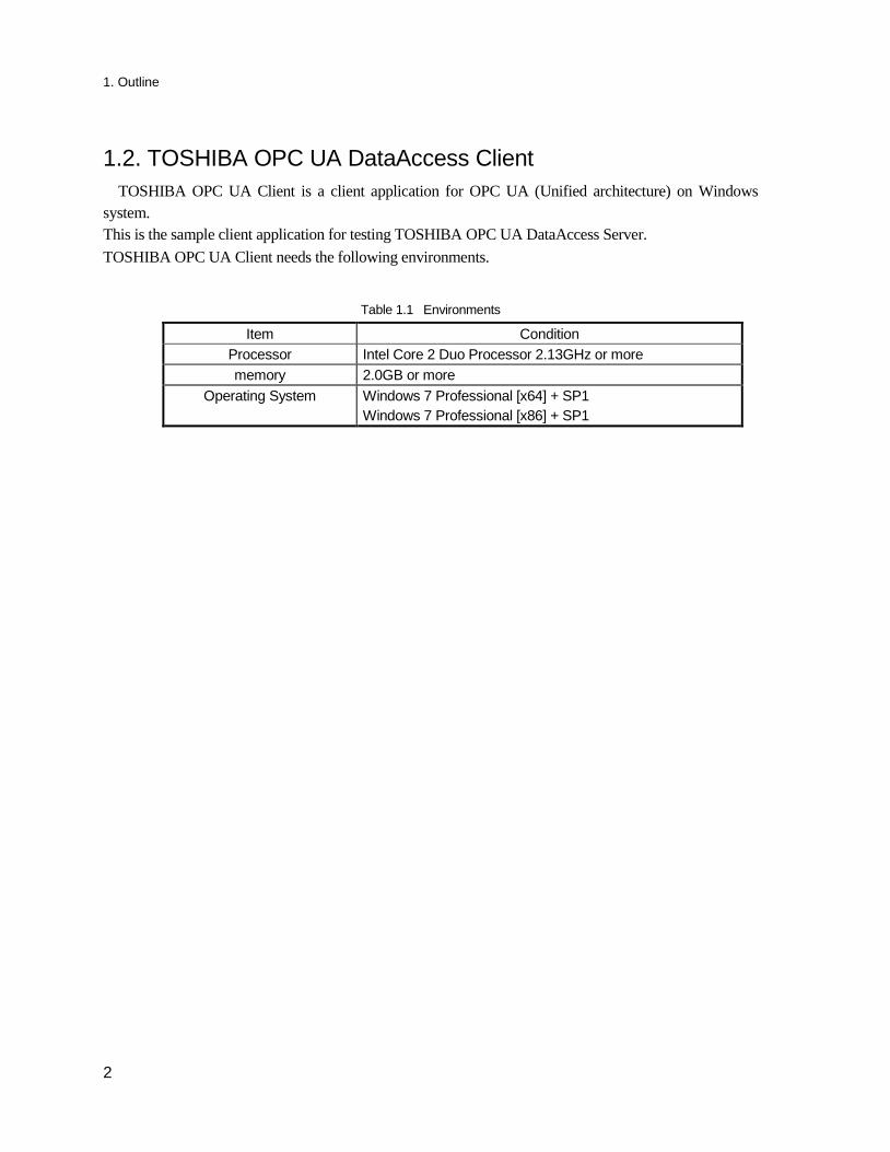
1.2. TOSHIBA OPC UA DataAccess Client TOSHIBA OPC UA Client is a client application for OPC UA (Unified architecture) on Windows
system. This is the sample client application for testing TOSHIBA OPC UA DataAccess Server. TOSHIBA OPC UA Client needs the following environments.
Table 1.1 Environments
Item Condition Processor Intel Core 2 Duo Processor 2.13GHz or more memory 2.0GB or more
Operating System Windows 7 Professional [x64] + SP1 Windows 7 Professional [x86] + SP1
2. Setting-Up
3
2. Setting-Up This chapter describes installation, repair and uninstall of TOSHIBA OPC UA Data Access Client software.
2.1. Preparation To install TOSHIBA OPC UA Data Access Client, the ‘Microsoft .NET Framework 4.5’ is required.
The following software isn’t installed on your PC with Windows 7OS, you shall install it by using the setup file under ‘dotNET Framework 4.5.1’ folder in the TOSHIBA OPC UA SERVER Software CD.
Microsoft .NET Framework4.5.1 Setup file : NDP451-KB2858728-x86-x64-AllOS-ENU.exe
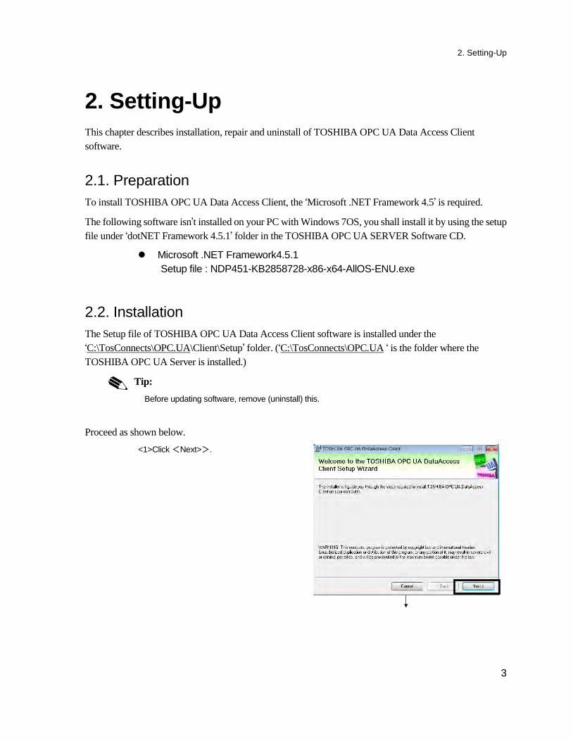
2.2. Installation The Setup file of TOSHIBA OPC UA Data Access Client software is installed under the ‘C:\TosConnects\OPC.UA\Client\Setup’ folder. (‘C:\TosConnects\OPC.UA ‘ is the folder where the TOSHIBA OPC UA Server is installed.)
Tip: Before updating software, remove (uninstall) this.
Proceed as shown below. <1>Click <Next>>.
2. Setting-Up
4
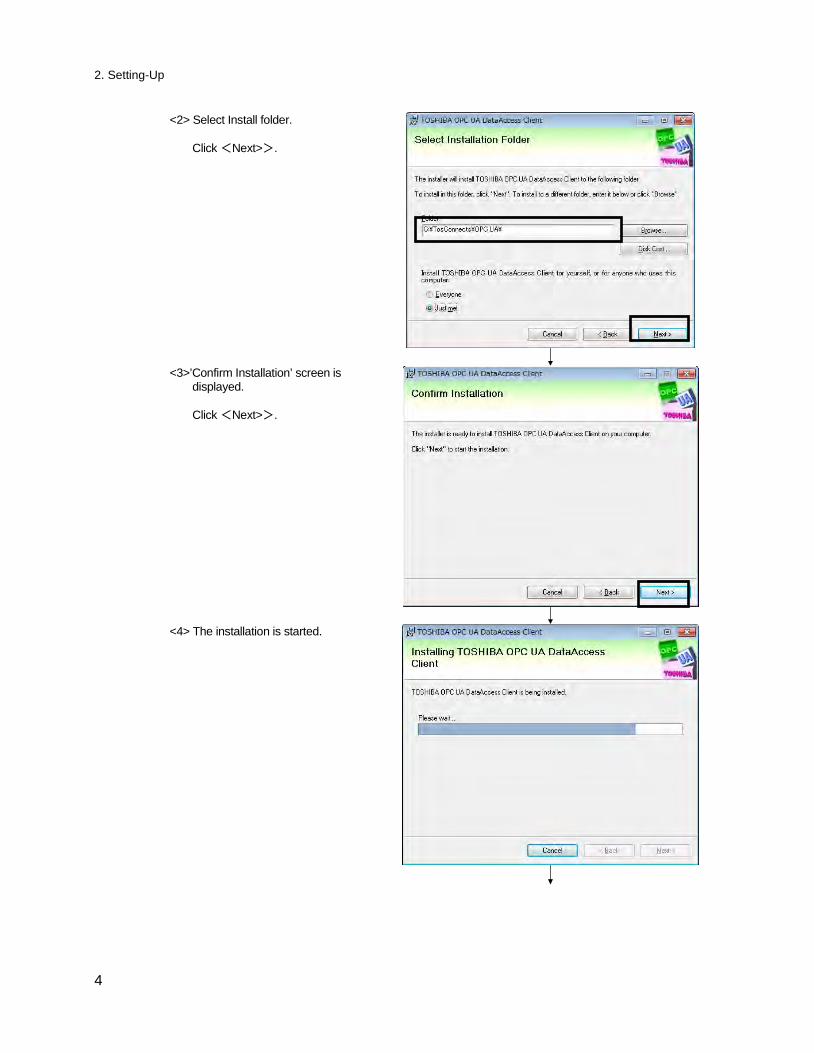
<2> Select Install folder. Click <Next>>.
<3>’Confirm Installation’ screen is
displayed. Click <Next>>.
<4> The installation is started.
2. Setting-Up
5
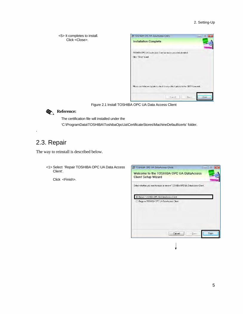
<5> It completes to install. Click <Close>.
Figure 2.1 Install TOSHIBA OPC UA Data Access Client
Reference: The certification file will installed under the
‘C:\ProgramData\TOSHIBA\ToshibaOpcUa\CertificateStores\MachineDefault\certs’ folder. . 2.3. Repair The way to reinstall is described below.
<1> Select ‘Repair TOSHIBA OPC UA Data Access
Client’. Click <Finish>.
2. Setting-Up
6
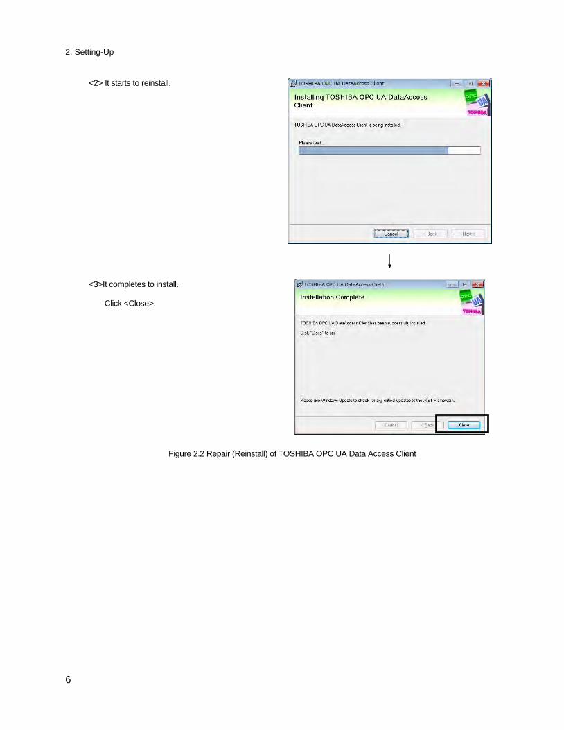
<2> It starts to reinstall.
<3>It completes to install. Click <Close>.
Figure 2.2 Repair (Reinstall) of TOSHIBA OPC UA Data Access Client
2. Setting-Up
7
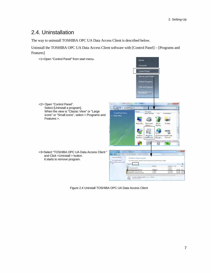
2.4. Uninstallation The way to uninstall TOSHIBA OPC UA Data Access Client is described below.
Uninstall the TOSHIBA OPC UA Data Access Client software with [Control Panel] – [Programs and Features]
<1>Open “Control Panel” from start menu.
<2> Open “Control Panel”. Select [Uninstall a program]. When the view is "Classic View" or "Large icons" or "Small icons", select < Programs and Features >.
<3>Select “TOSHIBA OPC UA Data Access Client ” and Click <Uninstall > button. It starts to remove program.
Figure 2.4 Uninstall TOSHIBA OPC UA Data Access Client
2. Setting-Up
8
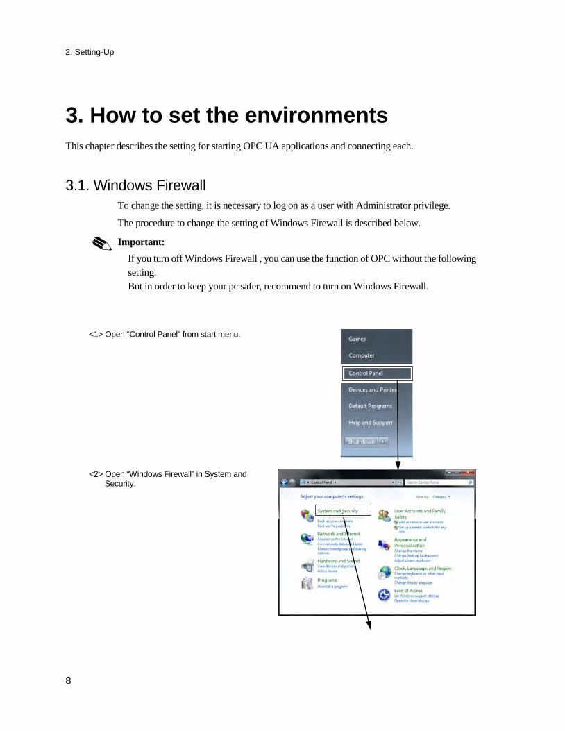
3. How to set the environments This chapter describes the setting for starting OPC UA applications and connecting each.
3.1. Windows Firewall To change the setting, it is necessary to log on as a user with Administrator privilege.
The procedure to change the setting of Windows Firewall is described below.
Important:
If you turn off Windows Firewall , you can use the function of OPC without the following setting. But in order to keep your pc safer, recommend to turn on Windows Firewall.
<1> Open “Control Panel” from start menu.
<2> Open “Windows Firewall” in System and Security.
3. How to set the environments t
9
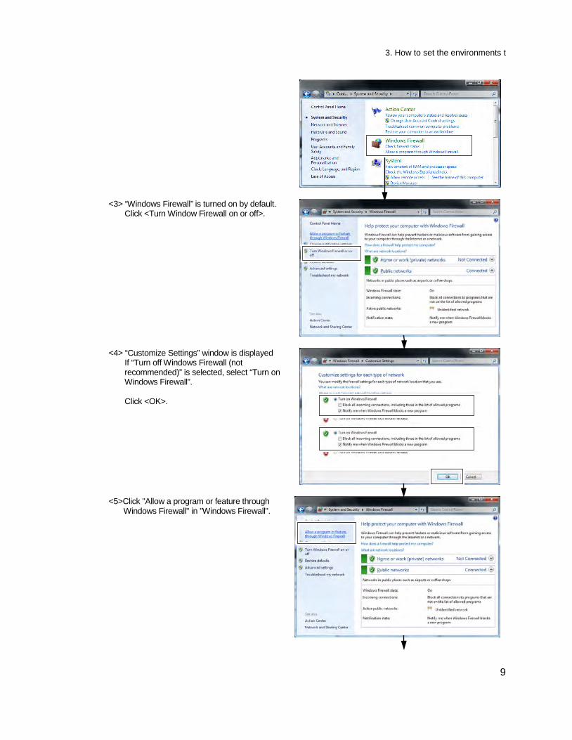
<3> “Windows Firewall” is turned on by default. Click <Turn Window Firewall on or off>.
<4> “Customize Settings” window is displayed If “Turn off Windows Firewall (not recommended)” is selected, select “Turn on Windows Firewall”. Click <OK>.
<5>Click "Allow a program or feature through Windows Firewall" in "Windows Firewall".
3. How to set the environments
10
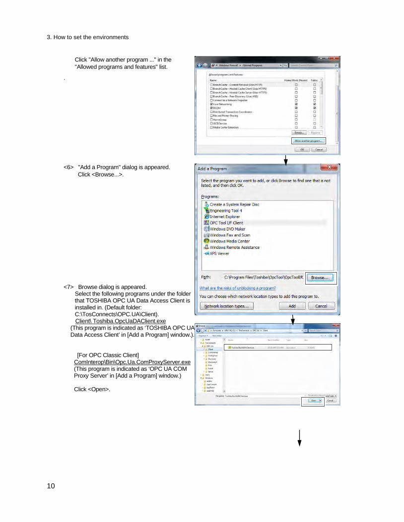
Click "Allow another program ..." in the "Allowed programs and features" list.
.
<6> "Add a Program" dialog is appeared. Click <Browse...>.
<7> Browse dialog is appeared. Select the following programs under the folder that TOSHIBA OPC UA Data Access Client is installed in. (Default folder: C:\TosConnects\OPC.UA\Client). Client\ Toshiba.OpcUaDAClient.exe
(This program is indicated as ‘TOSHIBA OPC UA Data Access Client’ in [Add a Program] window.).
[For OPC Classic Client] ComInterop\Bin\Opc.Ua.ComProxyServer.exe (This program is indicated as ‘OPC UA COM Proxy Server’ in [Add a Program] window.) Click <Open>.
3. How to set the environments t
11
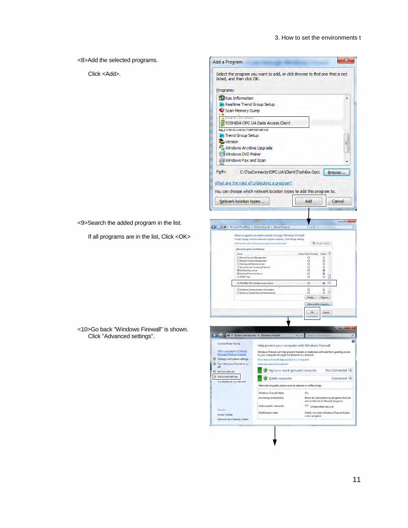
<8>Add the selected programs. Click <Add>.
<9>Search the added program in the list. If all programs are in the list, Click <OK>
<10>Go back "Windows Firewall" is shown. Click "Advanced settings".
3. How to set the environments
12
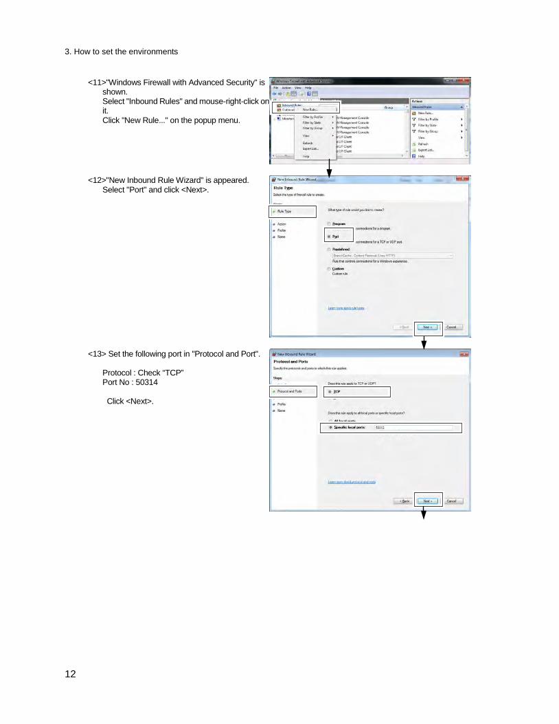
<11>"Windows Firewall with Advanced Security" is shown. Select "Inbound Rules" and mouse-right-click on it. Click "New Rule..." on the popup menu.
<12>"New Inbound Rule Wizard" is appeared. Select "Port" and click <Next>.
<13> Set the following port in "Protocol and Port". Protocol : Check “TCP” Port No : 50314 Click <Next>.
3. How to set the environments t
13
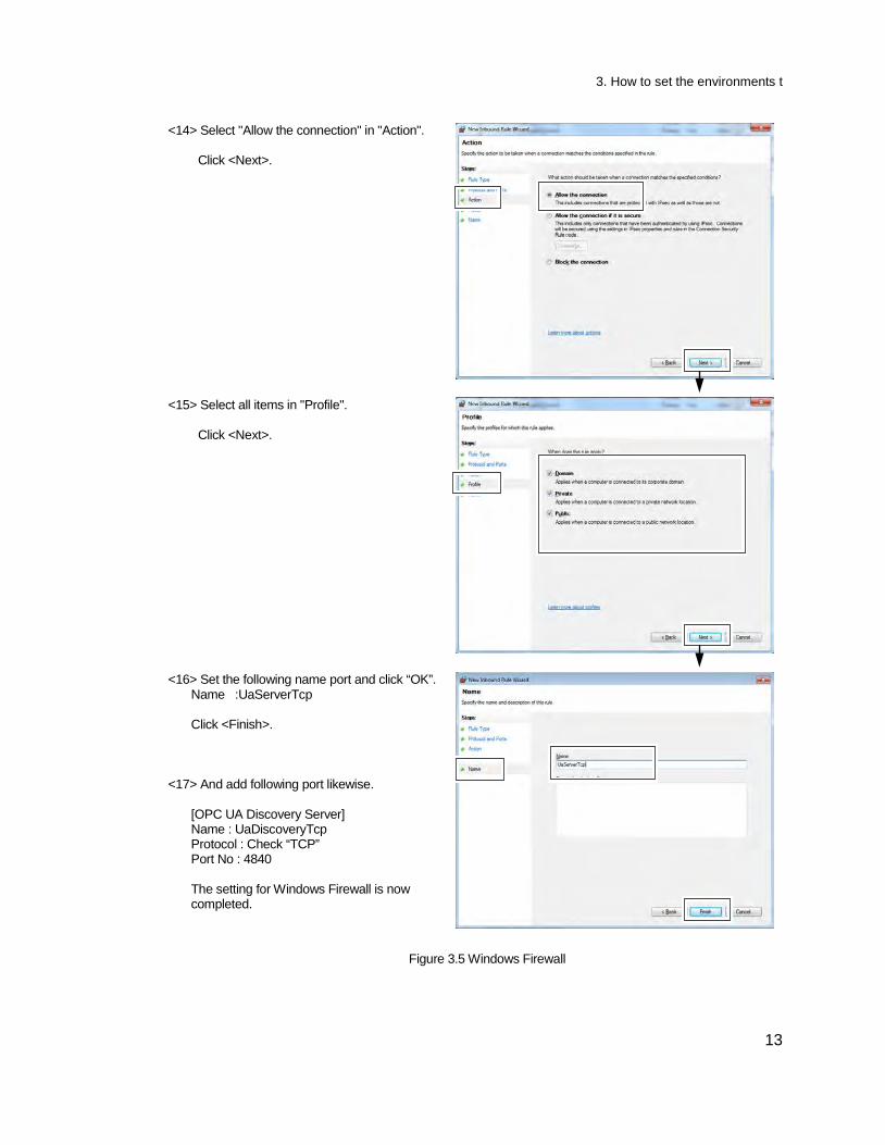
<14> Select "Allow the connection" in "Action". Click <Next>.
<15> Select all items in "Profile". Click <Next>.
<16> Set the following name port and click “OK”. Name :UaServerTcp Click <Finish>.
<17> And add following port likewise.
[OPC UA Discovery Server] Name : UaDiscoveryTcp Protocol : Check “TCP” Port No : 4840 The setting for Windows Firewall is now completed.
Figure 3.5 Windows Firewall

3. How to set the environments
14
4. Specification
15
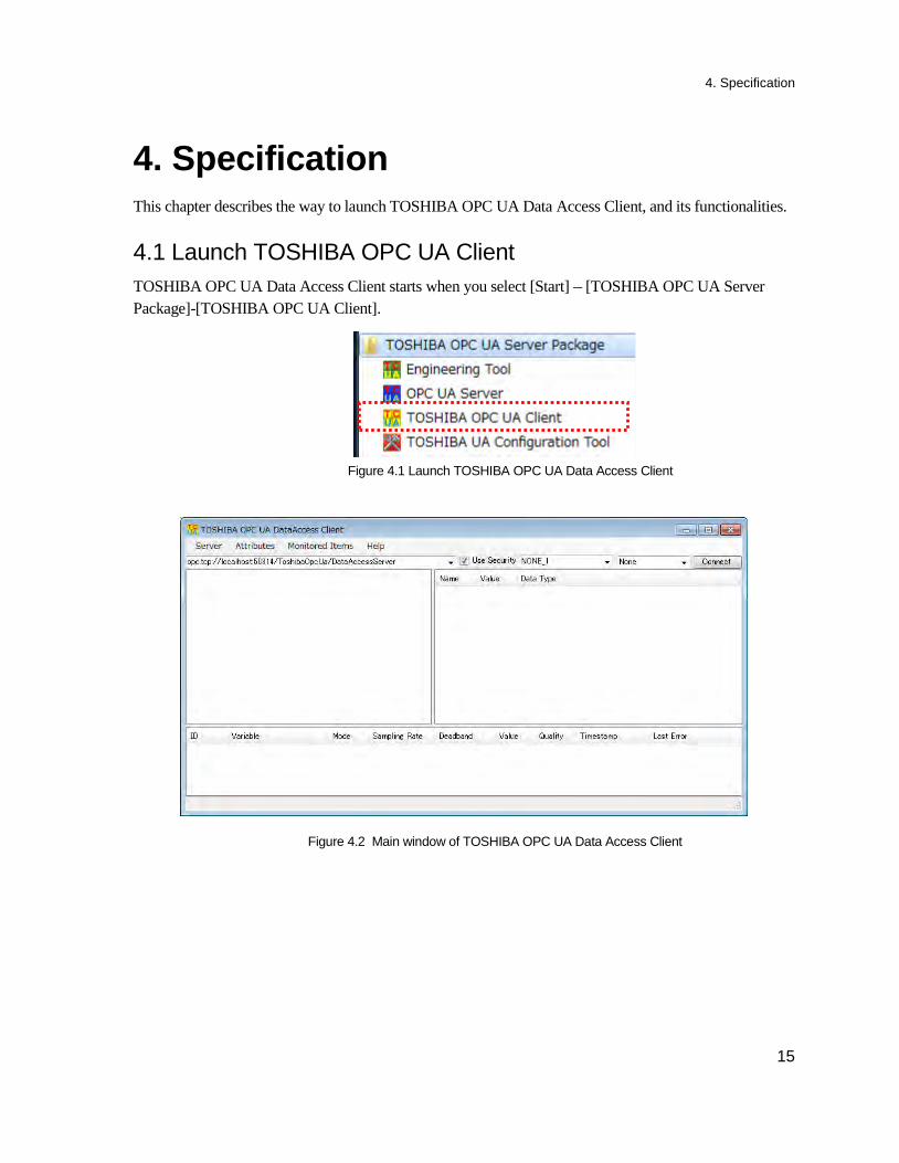
4. Specification This chapter describes the way to launch TOSHIBA OPC UA Data Access Client, and its functionalities. 4.1 Launch TOSHIBA OPC UA Client TOSHIBA OPC UA Data Access Client starts when you select [Start] – [TOSHIBA OPC UA Server Package]-[TOSHIBA OPC UA Client].
Figure 4.1 Launch TOSHIBA OPC UA Data Access Client
Figure 4.2 Main window of TOSHIBA OPC UA Data Access Client
4. Specification
16
4.2 Overview of functionalities This client application is for testing TOSHIBA OPC UA Server. The main functionalities are below.
- Connect / Disconnect with the Server
- Browse items
- Read/Write OPC items
- Monitor OPC items
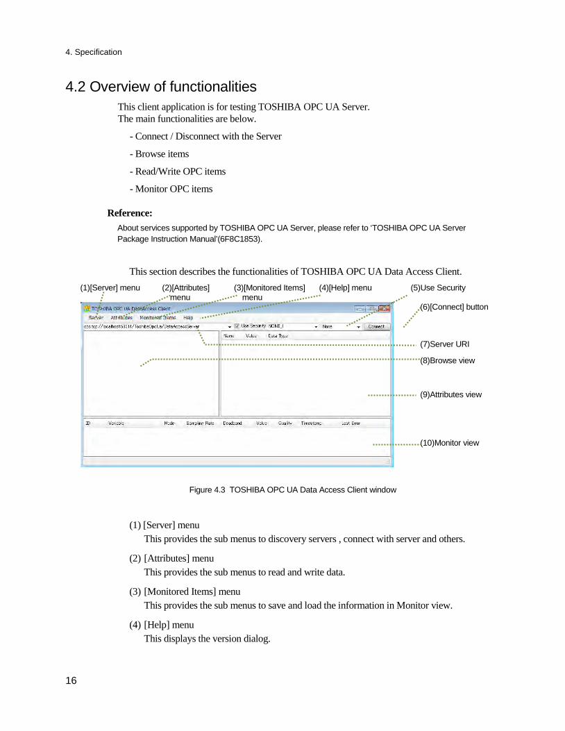
This section describes the functionalities of TOSHIBA OPC UA Data Access Client. (1)[Server] menu (2)[Attributes]
menu (3)[Monitored Items]
menu (4)[Help] menu (5)Use Security
(6)[Connect] button
(7)Server URI
(8)Browse view
(9)Attributes view
(10)Monitor view
Figure 4.3 TOSHIBA OPC UA Data Access Client window
(1) [Server] menu This provides the sub menus to discovery servers , connect with server and others.
(2) [Attributes] menu This provides the sub menus to read and write data.
(3) [Monitored Items] menu This provides the sub menus to save and load the information in Monitor view.
(4) [Help] menu This displays the version dialog.
Reference:
About services supported by TOSHIBA OPC UA Server, please refer to ‘TOSHIBA OPC UA Server Package Instruction Manual’(6F8C1853).
4. Specification
17
(5) Use Security This is for using the security to connect with the server. Checked : Use the security when this connects the client with OPC UA Server. Not checked: Not use the security when this connects the client with OPC UA Server.
TOSHIBA OPC UA Server supports the following security levels.
Table 4.1 Security Level
Security Level Security Mode Security Policy Security Level 0 None None Security Level 1 SignAndEncrypt Basic128Rsa15 Security Level 2 SignAndEncrypt Basic256
(6) [Connect] button By clicking this, it connects this client with the server.
(7) Server URI The target server’s URI is set.
(8) Browse view This displays the information of items in the target server.
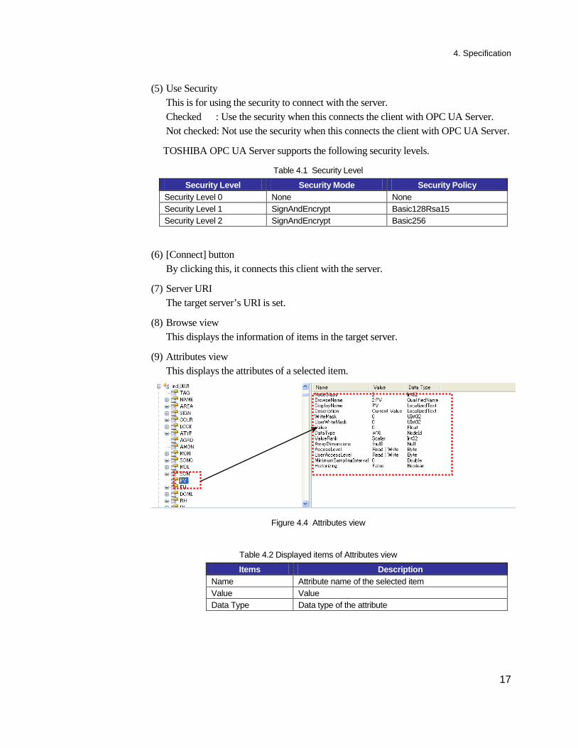
(9) Attributes view This displays the attributes of a selected item.
Figure 4.4 Attributes view
Table 4.2 Displayed items of Attributes view
Items Description Name Attribute name of the selected item Value Value Data Type Data type of the attribute
4. Specification
18
(10) Monitor view This displays the data registered by selecting [Monitor] sub-menu in the Browse view.
Table 4.3 Displayed items of Monitor view
Items Description ID ID assigned by the server when this is registered as
Monitored Item. Variable Name of a monitored item Mode Monitoring mode set in a monitored item. Sampling Rate Sampling rate set in a monitored item. Deadband Deadband set in a monitored item. Value Value of a monitored item Quality Quality of a monitored item Timestamp Timestamp when the data change is noticed. Last Error Last error
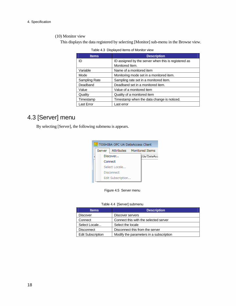
4.3 [Server] menu By selecting [Server], the following submenu is appears.
Figure 4.5 Server menu
Table 4.4 [Server] submenu
Items Description Discover Discover servers Connect Connect this with the selected server Select Locale... Select the locale Disconnect Disconnect this from the server Edit Subscription Modify the parameters in a subscription
4. Specification
19
4.3.1 [Discover] menu This discovers the servers registered in the selected host machine.
By selecting [Discover], ‘Discover Servers’ dialog appears.
Figure 4.6 'Discover Servers' dialog
(1) Host This is a host name that you want to discover servers in.
(2) [Find] button By clicking this, it discovers servers in the specified host in (1).
(3) List of servers The found servers are displayed.
(4) [OK] button By clicking this, this dialog disappears. The selected server becomes a target server. This is set in the Server URI in the main window.
(5) [Cancel] button By clicking this, this dialog disappears. The selection is disposed.
(3) List of servers
(2)[Find] button
(4)[OK]button (5)[Cancel]button
(1)Host
4. Specification
20
4.3.2 [Connect] menu This connects this client with the server.
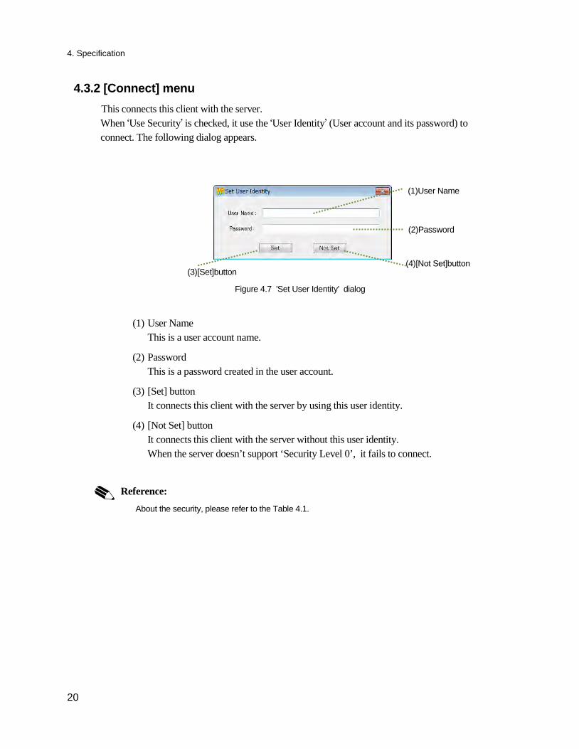
When ‘Use Security’ is checked, it use the ‘User Identity’ (User account and its password) to connect. The following dialog appears.
Figure 4.7 'Set User Identity' dialog
(1) User Name This is a user account name.
(2) Password This is a password created in the user account.
(3) [Set] button It connects this client with the server by using this user identity.
(4) [Not Set] button It connects this client with the server without this user identity. When the server doesn’t support ‘Security Level 0’, it fails to connect.
Reference:
About the security, please refer to the Table 4.1.
(2)Password
(1)User Name
(3)[Set]button (4)[Not Set]button
4. Specification
21
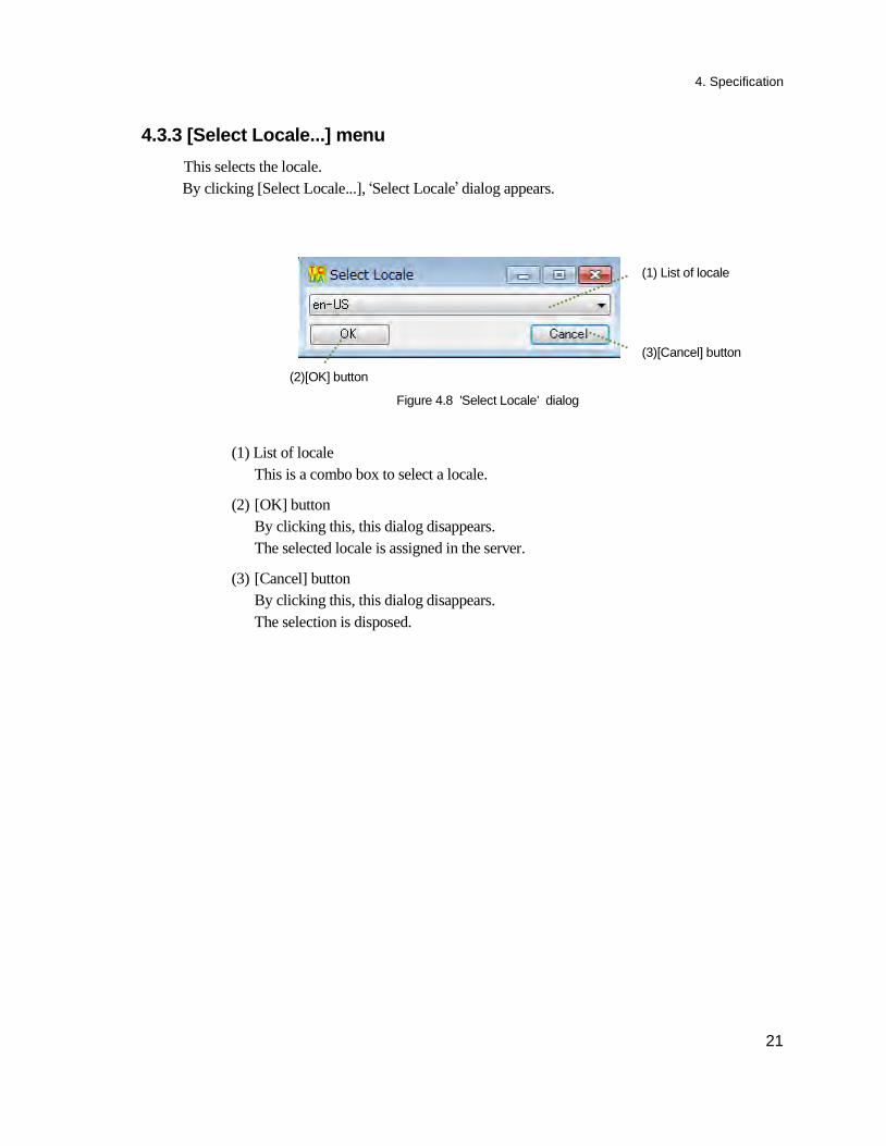
4.3.3 [Select Locale...] menu This selects the locale.
By clicking [Select Locale...], ‘Select Locale’ dialog appears.
Figure 4.8 'Select Locale' dialog
(1) List of locale This is a combo box to select a locale.
(2) [OK] button By clicking this, this dialog disappears. The selected locale is assigned in the server.
(3) [Cancel] button By clicking this, this dialog disappears. The selection is disposed.
(1) List of locale
(2)[OK] button
(3)[Cancel] button
4. Specification
22
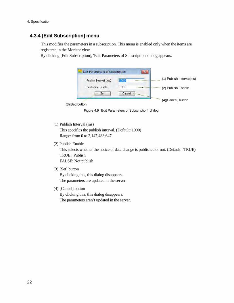
4.3.4 [Edit Subscription] menu This modifies the parameters in a subscription. This menu is enabled only when the items are
registered in the Monitor view. By clicking [Edit Subscription], ‘Edit Parameters of Subscription’ dialog appears.
Figure 4.9 'Edit Parameters of Subscription' dialog
(1) Publish Interval (ms) This specifies the publish interval. (Default: 1000) Range: from 0 to 2,147,483,647
(2) Publish Enable This selects whether the notice of data change is published or not. (Default : TRUE) TRUE : Publish FALSE: Not publish
(3) [Set] button By clicking this, this dialog disappears. The parameters are updated in the server.
(4) [Cancel] button By clicking this, this dialog disappears. The parameters aren’t updated in the server.
(1) Publish Interval(ms)
(3)[Set] button (4)[Cancel] button
(2) Publish Enable
4. Specification
23
4.4 [Attributes] menu By selecting [Attributes], the submenu to read and write data is appears.
Figure 5.10 Attributes menu
Table 4.5 [Attributes] submenu
Submenu Description Read/Write Values ... Read/Write data of the selected items.
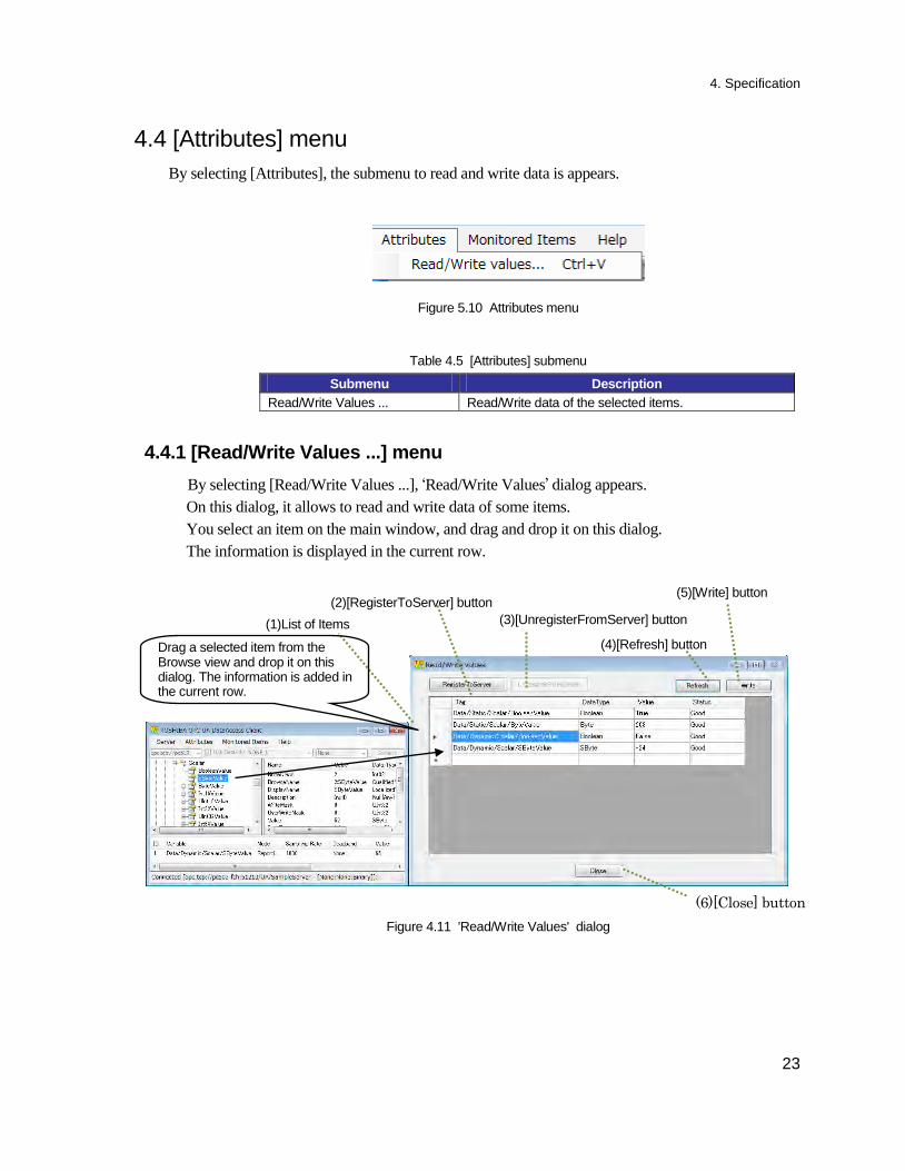
4.4.1 [Read/Write Values ...] menu By selecting [Read/Write Values ...], ‘Read/Write Values’ dialog appears.
On this dialog, it allows to read and write data of some items. You select an item on the main window, and drag and drop it on this dialog. The information is displayed in the current row.
Figure 4.11 'Read/Write Values' dialog
(2)[RegisterToServer] button (5)[Write] button
(4)[Refresh] button Drag a selected item from the Browse view and drop it on this dialog. The information is added in the current row.
(3)[UnregisterFromServer] button (1)List of Items
(6)[Close] button
4. Specification
24
(1) List of Items The informations of items that are dropped from the main window. The contents are below. - Tag : Item Name (Full path) (Read Only) - DataType : Datatype of a item (Read Only) - Value : Value of a item (Read/Write) - Status : Result of ‘Refresh’/’Write’ (Read Only)
(2) [RegisterToServer] button This carries out ‘RegisterNodes’ service. By clicking [RegisterToServer], [UnregisterFromServer] button becomes enabled and [RegisterToServer] button becomes disabled. And it prohibits to add a new row. After this procedure, ‘Refresh’/’Write’ requests use the return values of ‘RegisterNodes’ service.
(3) [UnregisterFromServer] button This carries out ‘UnregisterNodes’ service. By clicking [UnregisterFromServer], [UnregisterFrom RegisterToServer Server] button becomes enabled and [UnregisterFromServer] button becomes disabled. And it allows to add a new row. After this procedure, ‘Refresh’/’Write’ requests use the values of ‘Tag’ cell.
(4) [Refresh] button This reads the data of the registered items.
(5) [Write] button This writes values to the registered items.
(6) [Close] button By clicking this, this dialog disappears. The contents of this dialog is stored.
4. Specification
25
4.5 [Monitored Items] menu By selecting [Monitored Items], the submenu to save or load the information in the Monitor view is
appears.
Figure 4.12 Monitored Items menu
Table 4.6 [Monitored Items] submenu
Submenu Description Load Load the information of the monitored items that is saved
by [Save] menu. This loads the information of the file and registers the contents as the Monitor items into the server.
Save Save the information in the Monitor view. Monitoring Info. Displays the all information of the items in the Monitor
view.
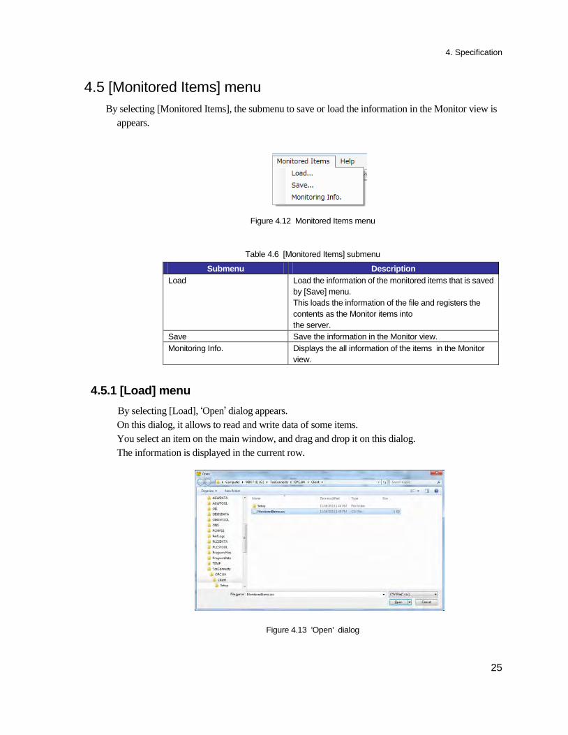
4.5.1 [Load] menu By selecting [Load], ‘Open’ dialog appears.
On this dialog, it allows to read and write data of some items. You select an item on the main window, and drag and drop it on this dialog. The information is displayed in the current row.
Figure 4.13 'Open' dialog
4. Specification
26
The result is displayed in the Monitor view.
Figure 4.14 Result example
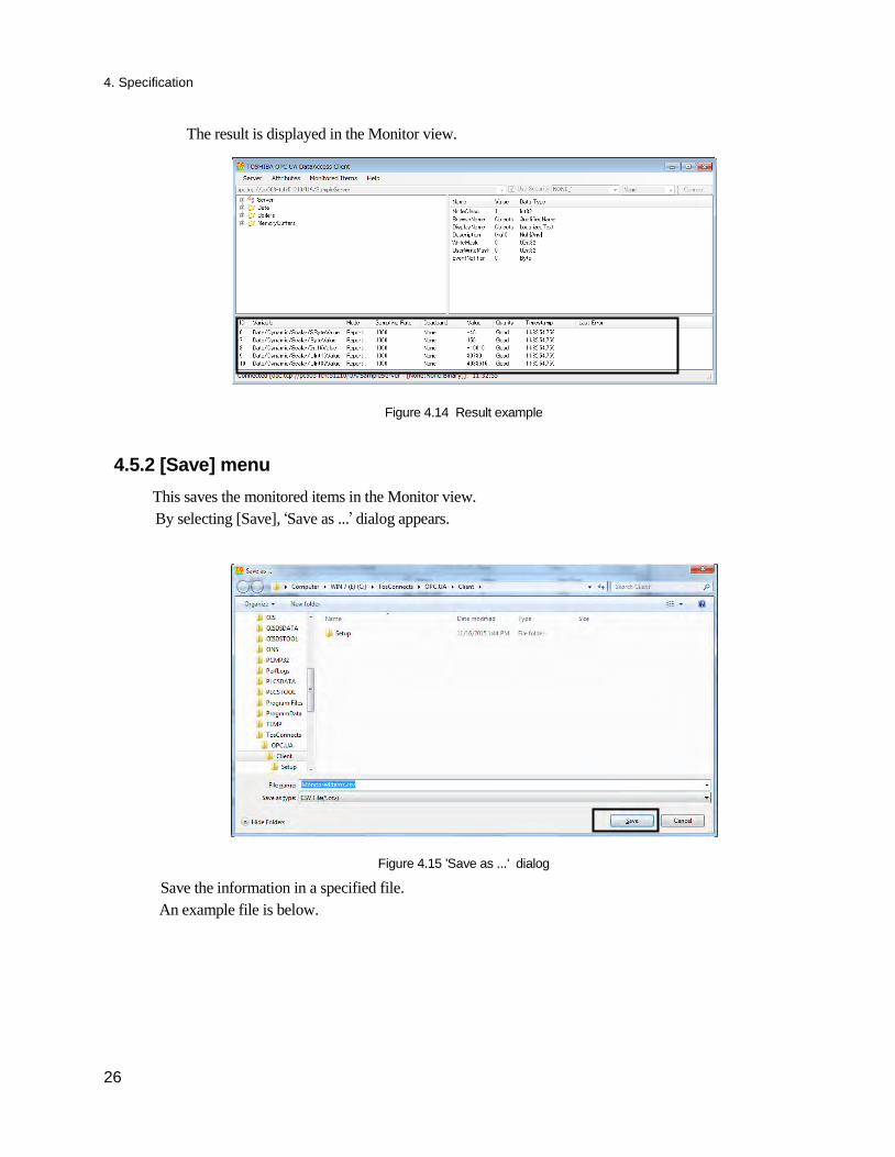
4.5.2 [Save] menu This saves the monitored items in the Monitor view.
By selecting [Save], ‘Save as ...’ dialog appears.
Figure 4.15 'Save as ...' dialog
Save the information in a specified file. An example file is below.
4. Specification
27
Figure 4.16 Example of a saved file
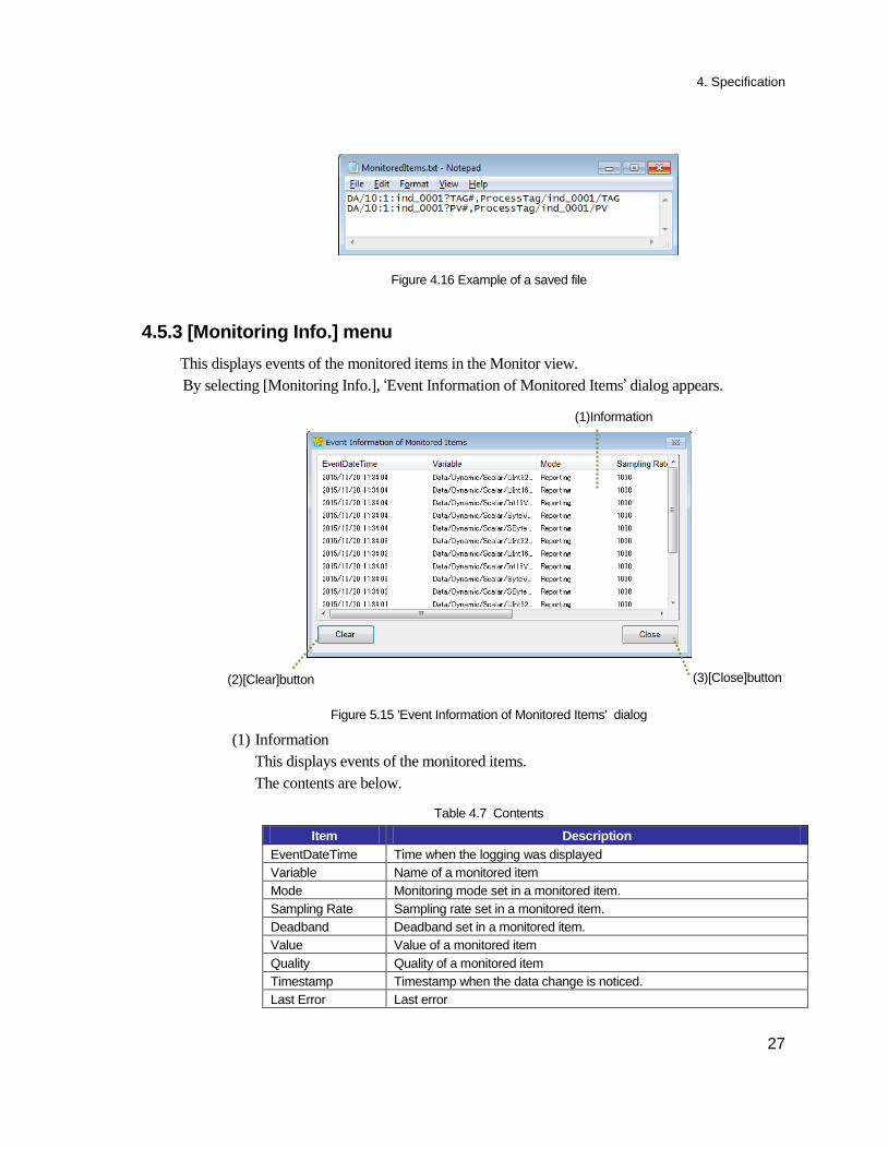
4.5.3 [Monitoring Info.] menu This displays events of the monitored items in the Monitor view.
By selecting [Monitoring Info.], ‘Event Information of Monitored Items’ dialog appears.
Figure 5.15 'Event Information of Monitored Items' dialog
(1) Information This displays events of the monitored items. The contents are below.
Table 4.7 Contents
Item Description EventDateTime Time when the logging was displayed Variable Name of a monitored item Mode Monitoring mode set in a monitored item. Sampling Rate Sampling rate set in a monitored item. Deadband Deadband set in a monitored item. Value Value of a monitored item Quality Quality of a monitored item Timestamp Timestamp when the data change is noticed. Last Error Last error
(2)[Clear]button (3)[Close]button
(1)Information
4. Specification
28
(2) [Clear] button This clears the list.
(3)[Close] button This close the dialog.
4.6 [Help] menu This displays the version information.
Figure 4.18 Help menu
Table 4.8 [Help] submenu
Submenu Description About TOSHIBA OPC UA Data Access Client …
Display the version information.
Figure 4.19 Version dialog
4. Specification
29
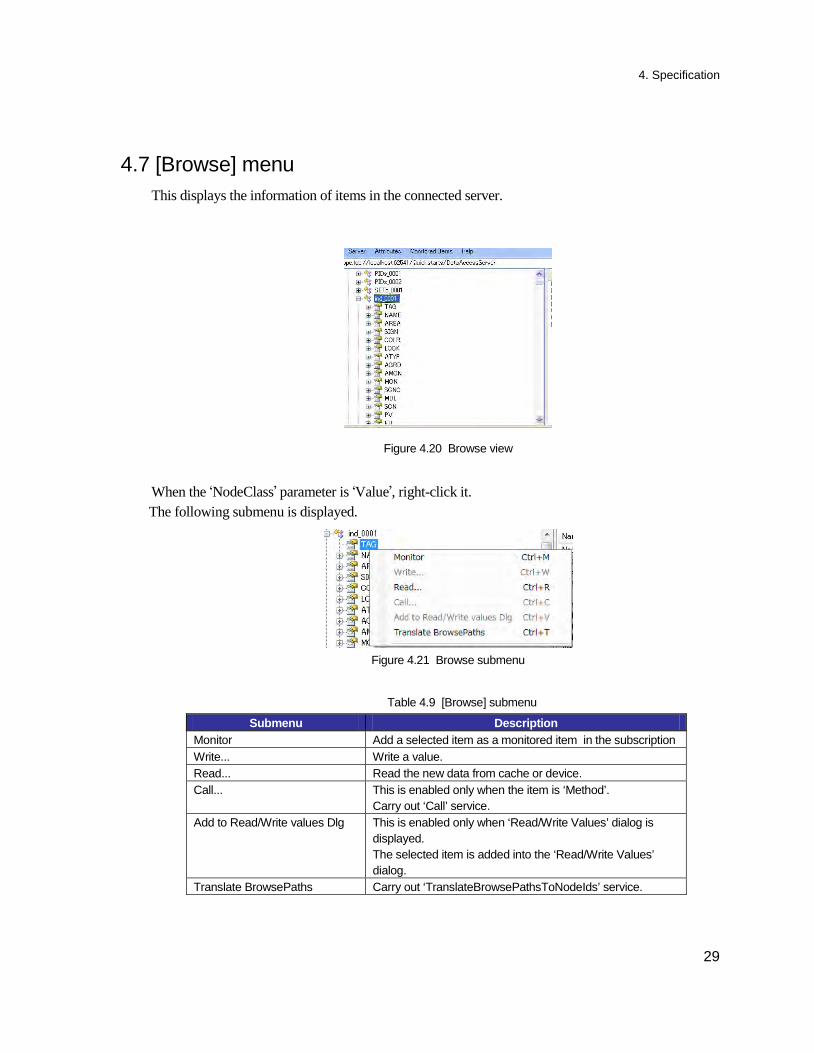
4.7 [Browse] menu This displays the information of items in the connected server.
Figure 4.20 Browse view
When the ‘NodeClass’ parameter is ‘Value’, right-click it. The following submenu is displayed.
Figure 4.21 Browse submenu
Table 4.9 [Browse] submenu
Submenu Description Monitor Add a selected item as a monitored item in the subscription Write... Write a value. Read... Read the new data from cache or device. Call... This is enabled only when the item is ‘Method’.
Carry out ‘Call’ service. Add to Read/Write values Dlg This is enabled only when ‘Read/Write Values’ dialog is
displayed. The selected item is added into the ‘Read/Write Values’ dialog.
Translate BrowsePaths Carry out ‘TranslateBrowsePathsToNodeIds’ service.
4. Specification
30
4.7.1 [Monitor] menu [Monitor] menu registers a selected item into the Subscription.
This menu can be selected in the popup menu shown by selecting an item in the Browse view and right-click it. After connecting with the server, ‘Edit Parameters of Subscription’ dialog appears. You set the parameters and click [Set] button.
Reference:
About the details, please read the paragraph of ‘Edit Parameters of Subscription’ menu.
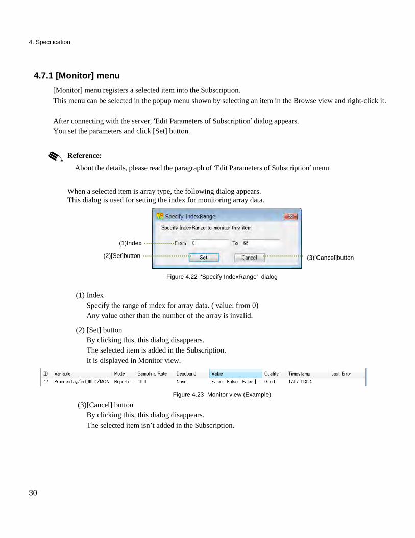
When a selected item is array type, the following dialog appears. This dialog is used for setting the index for monitoring array data.
Figure 4.22 'Specify IndexRange' dialog
(1) Index
Specify the range of index for array data. ( value: from 0) Any value other than the number of the array is invalid.
(2) [Set] button By clicking this, this dialog disappears. The selected item is added in the Subscription. It is displayed in Monitor view.
Figure 4.23 Monitor view (Example)
(3) [Cancel] button By clicking this, this dialog disappears. The selected item isn’t added in the Subscription.
(2)[Set]button (3)[Cancel]button
(1)Index
4. Specification
31
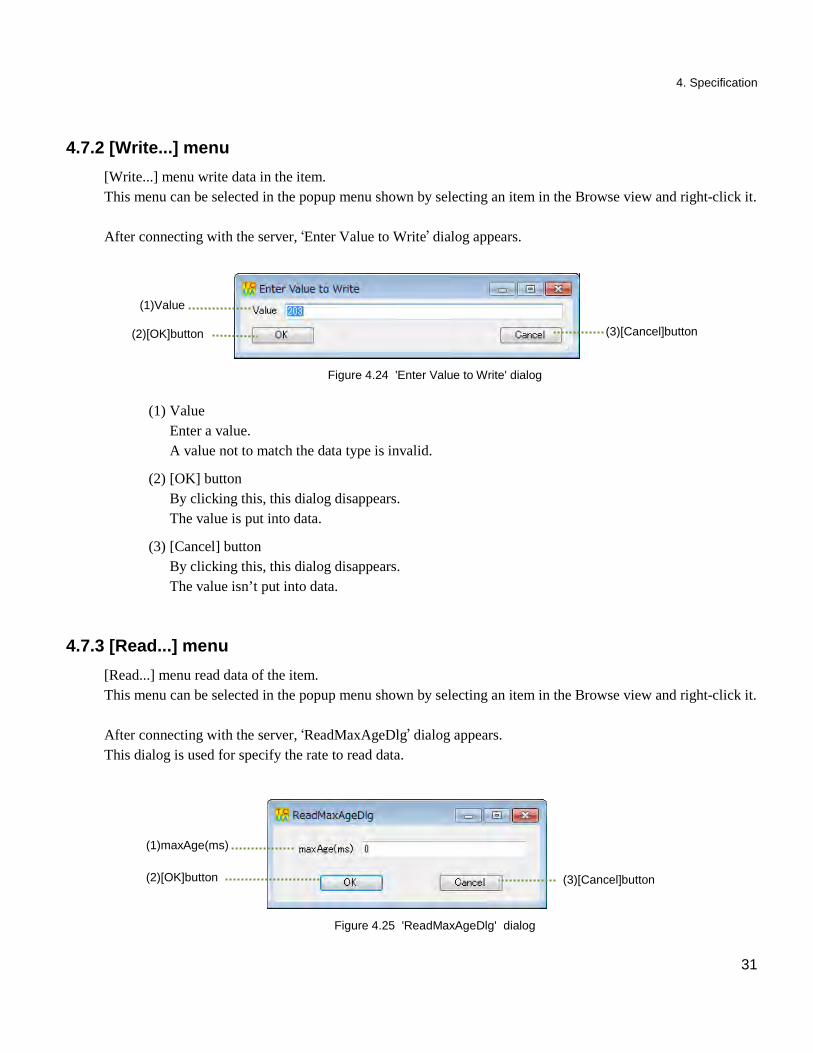
4.7.2 [Write...] menu [Write...] menu write data in the item.
This menu can be selected in the popup menu shown by selecting an item in the Browse view and right-click it. After connecting with the server, ‘Enter Value to Write’ dialog appears.
Figure 4.24 'Enter Value to Write' dialog
(1) Value
Enter a value. A value not to match the data type is invalid.
(2) [OK] button By clicking this, this dialog disappears. The value is put into data.
(3) [Cancel] button By clicking this, this dialog disappears. The value isn’t put into data.
4.7.3 [Read...] menu [Read...] menu read data of the item.
This menu can be selected in the popup menu shown by selecting an item in the Browse view and right-click it. After connecting with the server, ‘ReadMaxAgeDlg’ dialog appears. This dialog is used for specify the rate to read data.
Figure 4.25 'ReadMaxAgeDlg' dialog
(2)[OK]button (3)[Cancel]button
(1)Value
(2)[OK]button (3)[Cancel]button
(1)maxAge(ms)
4. Specification
32
(1) maxAge(ms)
Enter a rate to read data. maxAge = 0 : Read new data from the device. maxAge > 0 : When it is larger than the rate to update the cache, read a data from the cache. When it is smaller than the rate to update the cache, read a data from the device.
(2) [OK] button By clicking this, this dialog disappears. The data of item is read.
(3) [Cancel] button By clicking this, this dialog disappears. The data of item isn’t read.
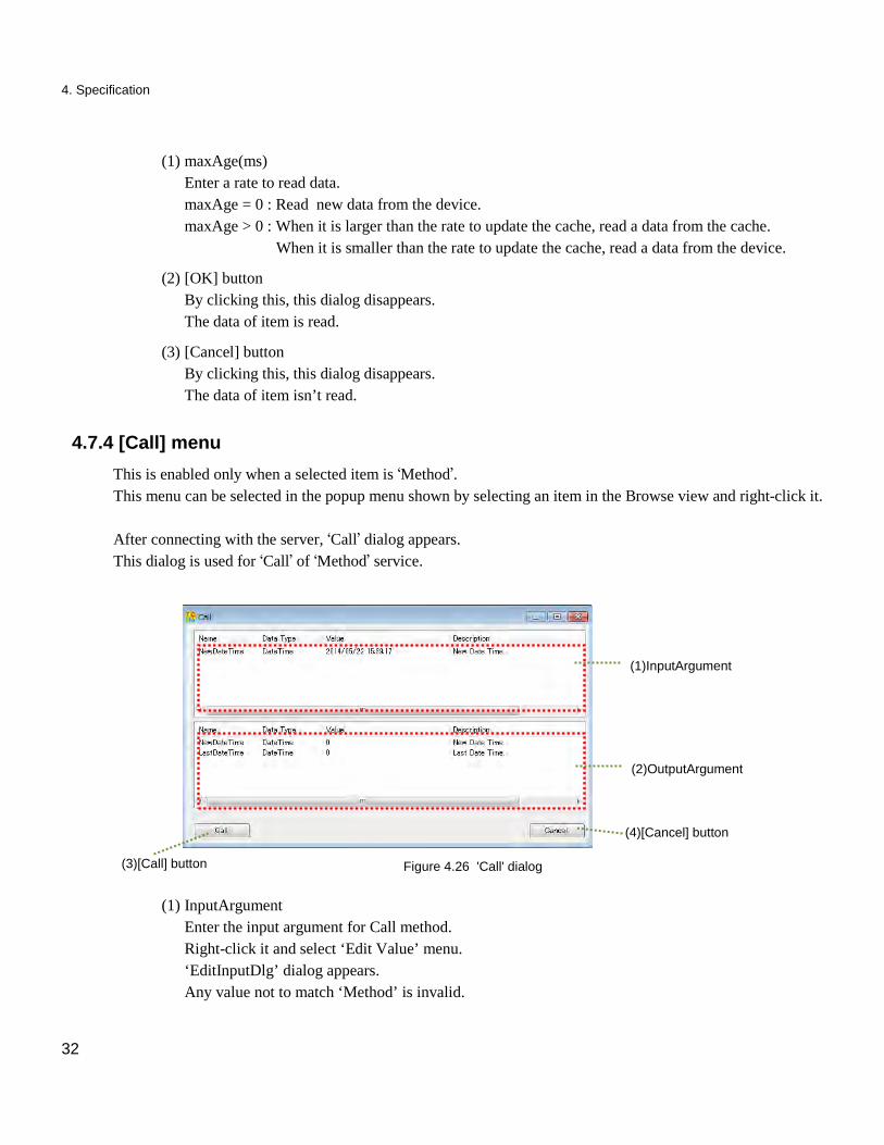
4.7.4 [Call] menu This is enabled only when a selected item is ‘Method’.
This menu can be selected in the popup menu shown by selecting an item in the Browse view and right-click it. After connecting with the server, ‘Call’ dialog appears. This dialog is used for ‘Call’ of ‘Method’ service.
Figure 4.26 'Call' dialog
(1) InputArgument
Enter the input argument for Call method. Right-click it and select ‘Edit Value’ menu. ‘EditInputDlg’ dialog appears. Any value not to match ‘Method’ is invalid.
(3)[Call] button
(4)[Cancel] button
(1)InputArgument
(2)OutputArgument
4. Specification
33
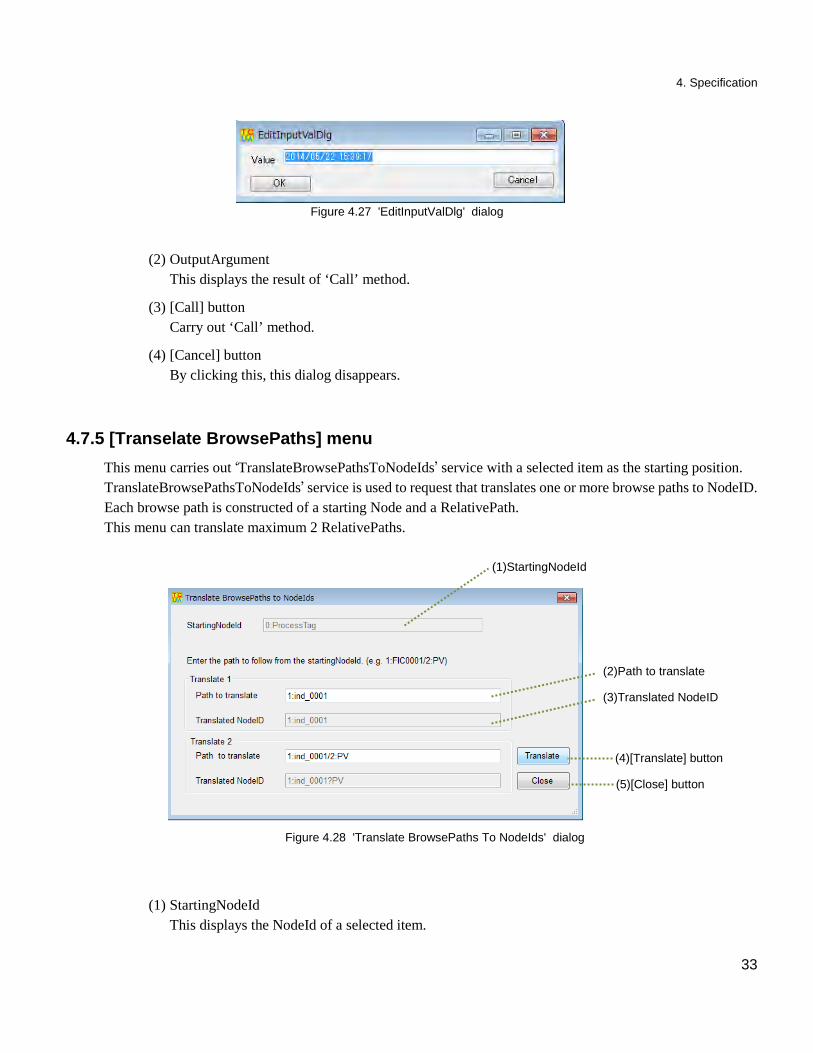
Figure 4.27 'EditInputValDlg' dialog
(2) OutputArgument This displays the result of ‘Call’ method.
(3) [Call] button Carry out ‘Call’ method.
(4) [Cancel] button By clicking this, this dialog disappears.
4.7.5 [Transelate BrowsePaths] menu This menu carries out ‘TranslateBrowsePathsToNodeIds’ service with a selected item as the starting position.
TranslateBrowsePathsToNodeIds’ service is used to request that translates one or more browse paths to NodeID. Each browse path is constructed of a starting Node and a RelativePath. This menu can translate maximum 2 RelativePaths.
Figure 4.28 'Translate BrowsePaths To NodeIds' dialog
(1) StartingNodeId This displays the NodeId of a selected item.
(5)[Close] button
(1)StartingNodeId
(2)Path to translate
(3)Translated NodeID
(4)[Translate] button
4. Specification
34
This NodeId is the starting NodeId for ‘TranslateBrowsePathsToNodeIds’ service.
(2) Path to translate This is the relative path from the specified starting NodeId. The way to specify a path depends on the rule of the Node ID of each server.
(3) Translated NodeID This is the result of ‘TranslateBrowsePathsToNodeIds’ service.
(4) [Translate] button Carry out ‘TranslateBrowsePathsToNodeIds’ service.
(5) [Close] button By clicking this, this dialog disappears.
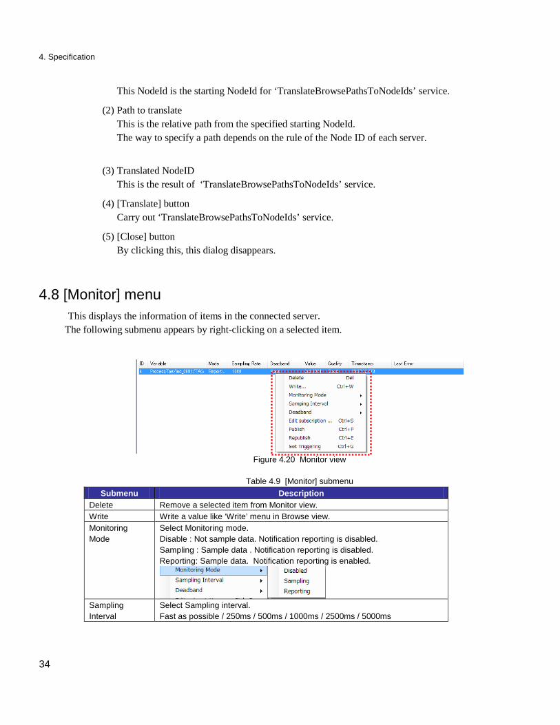
4.8 [Monitor] menu
This displays the information of items in the connected server. The following submenu appears by right-clicking on a selected item.
Figure 4.20 Monitor view
Table 4.9 [Monitor] submenu Submenu Description
Delete Remove a selected item from Monitor view. Write Write a value like ‘Write’ menu in Browse view. Monitoring Mode
Select Monitoring mode. Disable : Not sample data. Notification reporting is disabled. Sampling : Sample data . Notification reporting is disabled. Reporting: Sample data. Notification reporting is enabled.
Sampling Interval
Select Sampling interval. Fast as possible / 250ms / 500ms / 1000ms / 2500ms / 5000ms
4. Specification
35
Deadband Select the Deadband.
None Absolute Percentage
: No deadband : When there is the change of the value from a present
value, a notice of change occurs. Select among 5, 10 and 25.
: When there is the percentage change of the value from a present value, a notice of change occurs. Select among 1%, 5% and 10%. This isn’t disable for TOSHIBA OPC UA Server. When you select this, you will receive ‘BadFilterNotAllowed’ error in the monitored item.
Edit Subscription
Edit parameters of Subscription. This is same as ‘Edit Subscription’ menu of [Server] menu.
Publish Request to publish message. Republish Request to republish message. Set Triggering Set the trigger item.
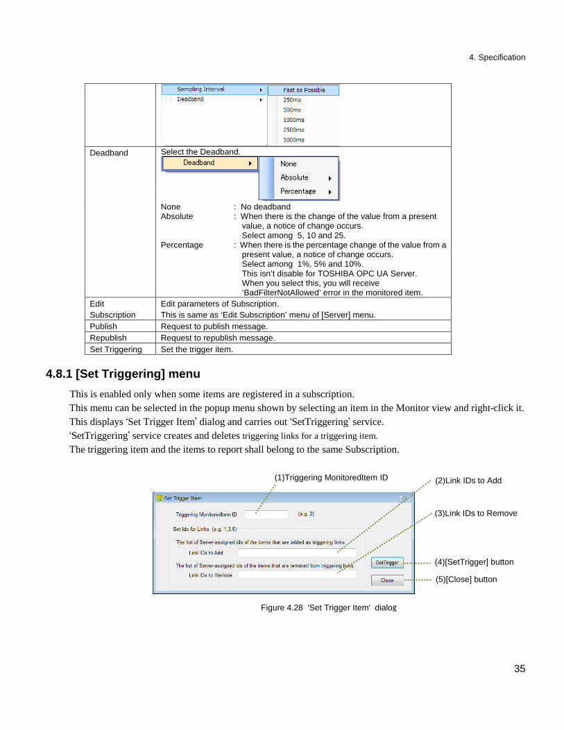
4.8.1 [Set Triggering] menu This is enabled only when some items are registered in a subscription.
This menu can be selected in the popup menu shown by selecting an item in the Monitor view and right-click it. This displays ‘Set Trigger Item’ dialog and carries out ‘SetTriggering’ service. ‘SetTriggering’ service creates and deletes triggering links for a triggering item. The triggering item and the items to report shall belong to the same Subscription.
Figure 4.28 'Set Trigger Item' dialog
(1)Triggering MonitoredItem ID
(4)[SetTrigger] button
(5)[Close] button
(3)Link IDs to Remove
(2)Link IDs to Add
4. Specification
36
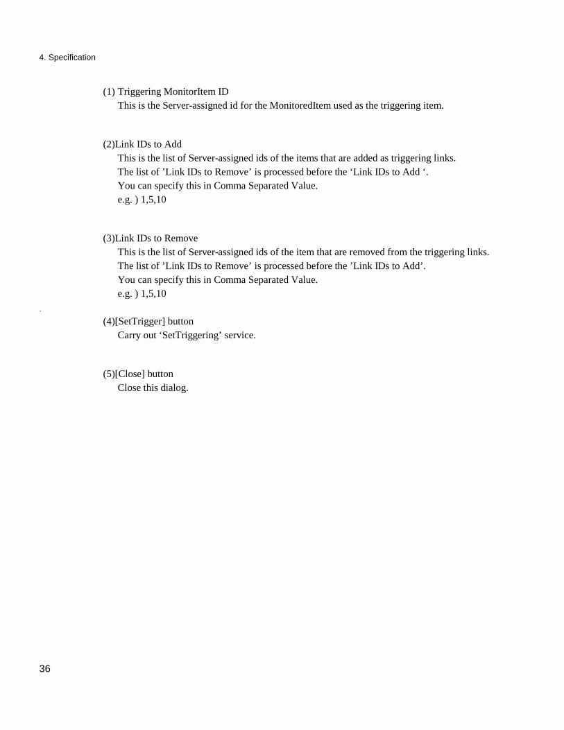
(1) Triggering MonitorItem ID This is the Server-assigned id for the MonitoredItem used as the triggering item.
(2)Link IDs to Add This is the list of Server-assigned ids of the items that are added as triggering links. The list of ’Link IDs to Remove’ is processed before the ‘Link IDs to Add ‘. You can specify this in Comma Separated Value. e.g. ) 1,5,10
(3)Link IDs to Remove This is the list of Server-assigned ids of the item that are removed from the triggering links. The list of ’Link IDs to Remove’ is processed before the ’Link IDs to Add’. You can specify this in Comma Separated Value. e.g. ) 1,5,10
.
(4)[SetTrigger] button Carry out ‘SetTriggering’ service.
(5)[Close] button Close this dialog.


Social Infrastructure Systems Company
Industrial Systems & Components Division
72-34, Horikawa-Cho, Saiwai-Ku, Kawasaki 212-8585, Japan
Recommended


![Handbuch TC3 OPC UA - Beckhoff Automation · OPC UA Sample Client [Grafische Beispielimplementierung eines OPC UA} 206] Clients um einen ersten Verbindungstest mit dem TwinCAT OPC](https://img.pdfslide.net/doc/110x75/5f0687177e708231d4186f52/handbuch-tc3-opc-ua-beckhoff-automation-opc-ua-sample-client-grafische-beispielimplementierung.jpg)