E6581335
TOSVERT VF-AS1
My Function Instruction Manual
January 2006
(C) Toshiba Schneider Inverter Corporation 2006 All rights reserved.
E6581335
- 1 -
Contents
CONTENTS ........................................................................................................................................................1
1. INTRODUCTION.....................................................................................................................................2
2. PARAMETERS USED ............................................................................................................................2
3. LOGIC INPUT/OUTPUT MY FUNCTION ...............................................................................................2
4. SETTING PARAMETERS ......................................................................................................................5
5. EXAMPLES OF SETTING....................................................................................................................12
6. ANALOG INPUT MY FUNCTION.........................................................................................................25
7. ANALOG OUTPUT MY FUNCTION.....................................................................................................29
APPENDIX 1 TABLE OF MY FUNCTION PARAMETERS.............................................................................30
APPENDIX 2 COMPUTING FUNCTIONS .......................................................................................................32
APPENDIX 3 INPUT TERMINAL FUNCTION SELECTION PARAMETERS.................................................33
APPENDIX 4 OUTPUT TERMINAL FUNCTION SELECTION PARAMETERS.............................................35
APPENDIX 5 INTERNAL DATA ......................................................................................................................39
APPENDIX 6 EXAMPLES OF COMPUTING FUNCTION SETTINGS ...........................................................41
E6581335
- 2 -
1. IntroductionVFAS1’s My function adds programming capability to inverter’s input/output signals to respond tocustomer needs without external relays or a PLC (programmable logic controller) in some cases.Therefore, My function makes it possible to reduce the space and cost required for the system.My function has three types in below:1. Logic input/output My function simplifies relay sequence operations.2. Analog input My function changes parameter settings by the analog input signals.3. Analog output My function gets the analog output signals of the maximum and minimum valuesdisplayed by the monitor function.⇒ For details of each function, refer to the relevant section.
2. Parameters usedMy functions use the parameters to .⇒ For details of each parameter, refer to the relevant section.
3. Logic input/output My functionThis chapter explains the logic input/output My function, which is typified by the combinedterminal function that combines the functions of the inverter’s input and output terminals and therelay sequence function that combines logic operation functions.
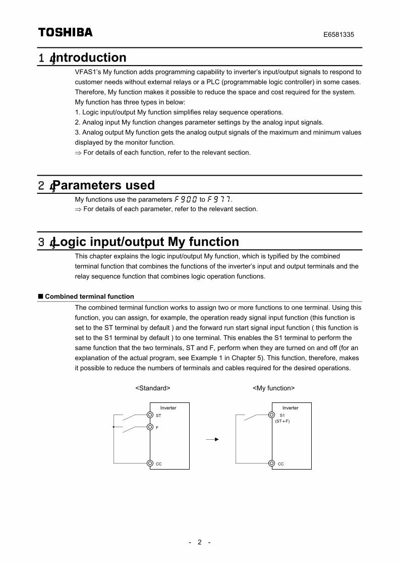
Combined terminal functionThe combined terminal function works to assign two or more functions to one terminal. Using thisfunction, you can assign, for example, the operation ready signal input function (this function isset to the ST terminal by default ) and the forward run start signal input function ( this function isset to the S1 terminal by default ) to one terminal. This enables the S1 terminal to perform thesame function that the two terminals, ST and F, perform when they are turned on and off (for anexplanation of the actual program, see Example 1 in Chapter 5). This function, therefore, makesit possible to reduce the numbers of terminals and cables required for the desired operations.
<Standard> <My function>
ST
F
CC
S1(ST+F)
CC
Inverter Inverter
E6581335
- 3 -
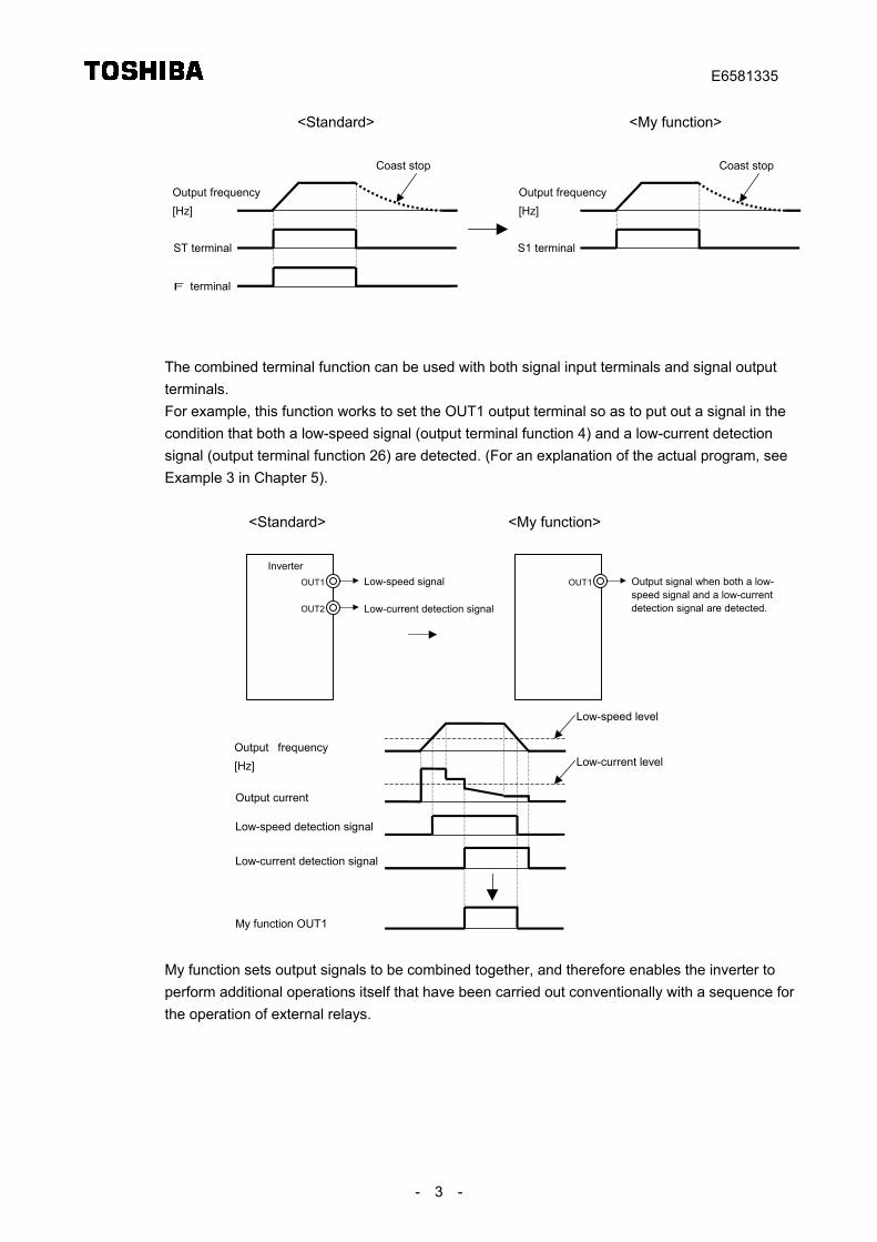
<Standard> <My function>
Output frequency[Hz]
ST terminal
F terminal
Coast stop Coast stop
S1 terminal
Output frequency[Hz]
The combined terminal function can be used with both signal input terminals and signal outputterminals.For example, this function works to set the OUT1 output terminal so as to put out a signal in thecondition that both a low-speed signal (output terminal function 4) and a low-current detectionsignal (output terminal function 26) are detected. (For an explanation of the actual program, seeExample 3 in Chapter 5).
<Standard> <My function>
OUT1
OUT2
Low-speed signal
Low-current detection signal
OUT1 Output signal when both a low-speed signal and a low-currentdetection signal are detected.
Inverter
Output frequency[Hz]
Output current
Low-speed detection signal
Low-current detection signal
My function OUT1
Low-speed level
Low-current level
My function sets output signals to be combined together, and therefore enables the inverter toperform additional operations itself that have been carried out conventionally with a sequence forthe operation of external relays.
E6581335
- 4 -
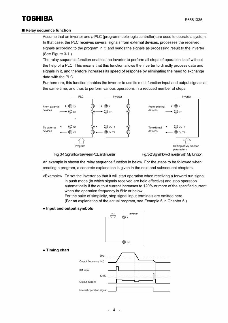
Relay sequence functionAssume that an inverter and a PLC (programmable logic controller) are used to operate a system.In that case, the PLC receives several signals from external devices, processes the receivedsignals according to the program in it, and sends the signals as processing result to the inverter .(See Figure 3-1.)The relay sequence function enables the inverter to perform all steps of operation itself withoutthe help of a PLC. This means that this function allows the inverter to directly process data andsignals in it, and therefore increases its speed of response by eliminating the need to exchangedata with the PLC.Furthermore, this function enables the inverter to use its multi-function input and output signals atthe same time, and thus to perform various operations in a reduced number of steps.
X1
X2
From externaldevices
To externaldevices
Q1
Q2
~
F
ST
OUT1
OUT2
~
PLC Inverter
Program
F
ST
From externaldevices
To externaldevices
OUT1
OUT2
~
Inverter
Setting of My functionparameters
Fig. 3-1 Signal flow between PCL and inverter Fig. 3-2 Signal flow of inverter with My function
An example is shown the relay sequence function in below. For the steps to be followed whencreating a program, a concrete explanation is given in the next and subsequent chapters.
«Example» To set the inverter so that it will start operation when receiving a forward run signalin push mode (in which signals received are held effective) and stop operationautomatically if the output current increases to 120% or more of the specified currentwhen the operation frequency is 5Hz or below.For the sake of simplicity, stop signal input terminals are omitted here.(For an explanation of the actual program, see Example 6 in Chapter 5.)
● Input and output symbols
F
CC
IX1 Inverter
● Timing chart
Output frequency [Hz]
Output current
Internal operation signal
5Hz
120%
IX1 input
E6581335
- 5 -
4. Setting parametersThis chapter explains how to set parameters related to the logic input/output My function usingexamples of setting, the composition of My functions, and the rules for them.
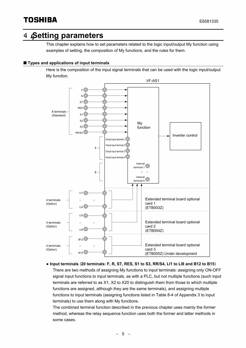
Types and applications of input terminalsHere is the composition of the input signal terminals that can be used with the logic input/outputMy function.
F
R
ST
RES
S1
S2
S3
RR/S4
LI1
LI4
~ ~
Myfunction
Internalterminal 8
~ ~
8 terminals(Standard)
Virtual input terminal 1
Virtual input terminal 2
Virtual input terminal 3
Virtual input terminal 4
4
Internalterminal 1
8
4 terminals(Option)
Inverter control
Extended terminal board optionalcard 1(ETB003Z)
Extended terminal board optionalcard 2(ETB004Z)
Extended terminal board optionalcard 3(ETB005Z) Under development
VF-AS1
LI5
LI8
~ ~4 terminals(Option)
B15
~ ~4 terminals(Option)
B12
● Input terminals (20 terminals: F, R, ST, RES, S1 to S3, RR/S4, LI1 to LI8 and B12 to B15)There are two methods of assigning My functions to input terminals: assigning only ON-OFFsignal input functions to input terminals, as with a PLC, but not multiple functions (such inputterminals are referred to as X1, X2 to X20 to distinguish them from those to which multiplefunctions are assigned, although they are the same terminals), and assigning multiplefunctions to input terminals (assigning functions listed in Table 8-4 of Appendix 3 to inputterminals) to use them along with My functions.The combined terminal function described in the previous chapter uses mainly the formermethod, whereas the relay sequence function uses both the former and latter methods insome cases.
E6581335
- 6 -
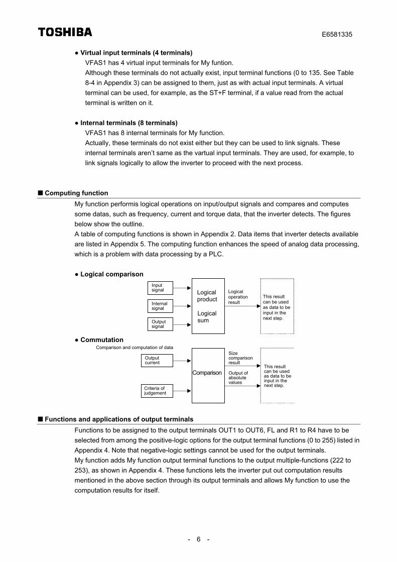
● Virtual input terminals (4 terminals)VFAS1 has 4 virtual input terminals for My funtion.Although these terminals do not actually exist, input terminal functions (0 to 135. See Table8-4 in Appendix 3) can be assigned to them, just as with actual input terminals. A virtualterminal can be used, for example, as the ST+F terminal, if a value read from the actualterminal is written on it.
● Internal terminals (8 terminals)VFAS1 has 8 internal terminals for My function.Actually, these terminals do not exist either but they can be used to link signals. Theseinternal terminals aren’t same as the vartual input terminals. They are used, for example, tolink signals logically to allow the inverter to proceed with the next process.
Computing functionMy function performis logical operations on input/output signals and compares and computessome datas, such as frequency, current and torque data, that the inverter detects. The figuresbelow show the outline.A table of computing functions is shown in Appendix 2. Data items that inverter detects availableare listed in Appendix 5. The computing function enhances the speed of analog data processing,which is a problem with data processing by a PLC.
● Logical comparison
Logicalproduct
Logicalsum
Inputsignal Logical
operationresult
This resultcan be usedas data to beinput in thenext step.
Internalsignal
Outputsignal
● Commutation
Comparison
Outputcurrent
Criteria ofjudgement
Sizecomparisonresult
This resultcan be usedas data to beinput in thenext step.
Comparison and computation of data
Output ofabsolutevalues
Functions and applications of output terminalsFunctions to be assigned to the output terminals OUT1 to OUT6, FL and R1 to R4 have to beselected from among the positive-logic options for the output terminal functions (0 to 255) listed inAppendix 4. Note that negative-logic settings cannot be used for the output terminals.My function adds My function output terminal functions to the output multiple-functions (222 to253), as shown in Appendix 4. These functions lets the inverter put out computation resultsmentioned in the above section through its output terminals and allows My function to use thecomputation results for itself.
E6581335
- 7 -
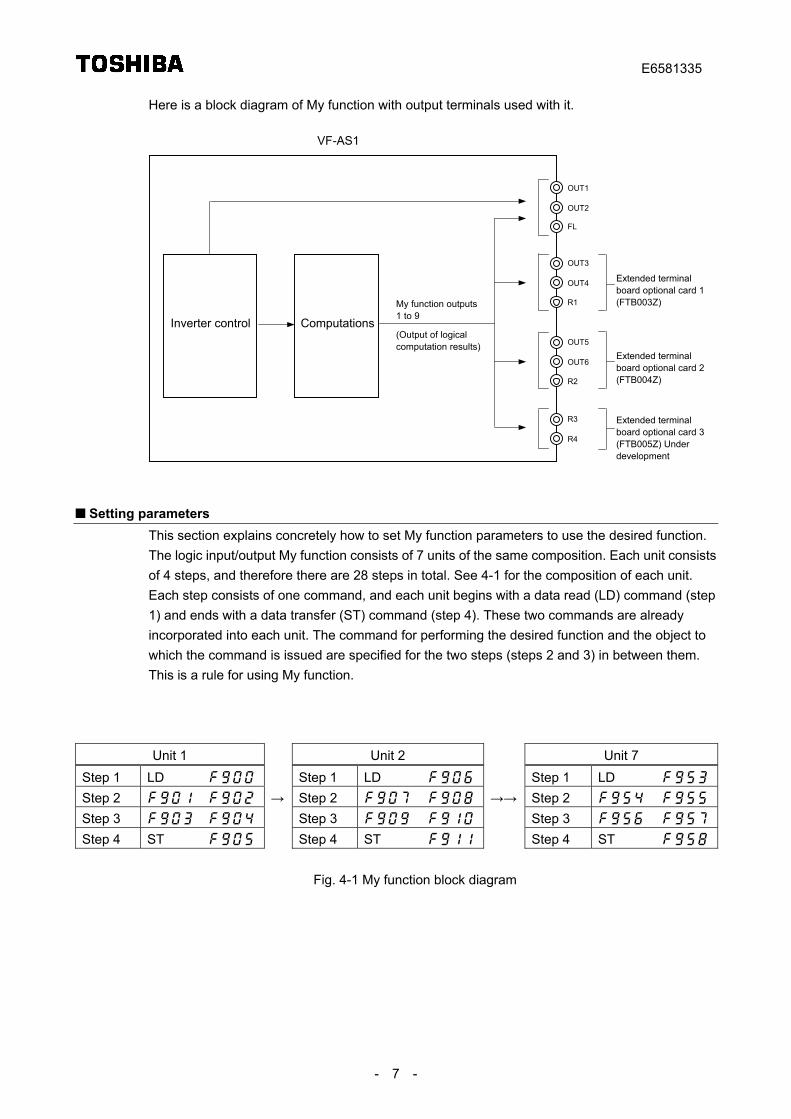
Here is a block diagram of My function with output terminals used with it.
Inverter control
VF-AS1
OUT1
Computationsb M f i
OUT2
FL
OUT3
OUT4
R1
Extended terminalboard optional card 1(FTB003Z)
OUT5
OUT6
R2
Extended terminalboard optional card 2(FTB004Z)
My function outputs1 to 9
(Output of logicalcomputation results)
R3
R4
Extended terminalboard optional card 3(FTB005Z) Underdevelopment
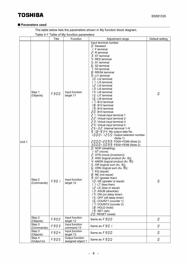
Setting parametersThis section explains concretely how to set My function parameters to use the desired function.The logic input/output My function consists of 7 units of the same composition. Each unit consistsof 4 steps, and therefore there are 28 steps in total. See 4-1 for the composition of each unit.Each step consists of one command, and each unit begins with a data read (LD) command (step1) and ends with a data transfer (ST) command (step 4). These two commands are alreadyincorporated into each unit. The command for performing the desired function and the object towhich the command is issued are specified for the two steps (steps 2 and 3) in between them.This is a rule for using My function.
Unit 1 Unit 2 Unit 7Step 1 LD Step 1 LD Step 1 LD
Step 2 → Step 2 →→ Step 2
Step 3 Step 3 Step 3
Step 4 ST Step 4 ST Step 4 ST
Fig. 4-1 My function block diagram
E6581335
- 8 -
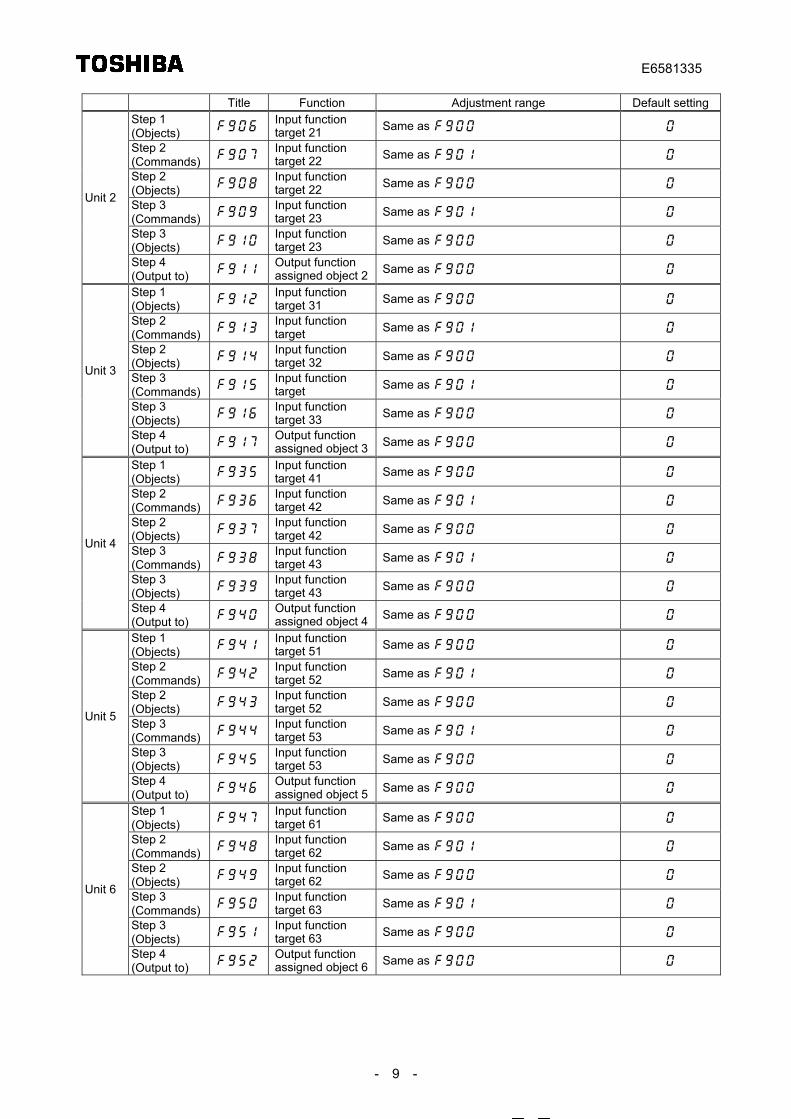
Parameters usedThe table below lists the parameters shown in My function block diagram.Table 4-1 Table of My function parameters
Title Function Adjustment range Default setting
Step 1(Objects)
Input functiontarget 11
Input terminal number: Deselect: F terminal: R terminal: ST terminal: RES terminal: S1 terminal: S2 terminal: S3 terminal: RR/S4 terminal: LI1 terminal: LI2 terminal: LI3 terminal: LI4 terminal: LI5 terminal: LI6 terminal: LI7 terminal: LI8 terminal: B12 terminal: B13 terminal: B14 terminal: B15 terminal: Virtual input terminal 1: Virtual input terminal 2: Virtual input terminal 3: Virtual input terminal 4~: Internal terminal 1~8~: My output data No.~: Output selection number
(Note 1)~: FD00~FD99 (Note 2)~: FE00~FE99 (Note 2)
Step 2(Commands)
Input functiontarget 12
: NOP (disabling): ST (move): STN (move (inversion)): AND (logical product (A∩B)): ANDN (logical product (A∩B)): OR (logical sum (A∪B)): ORN (logical sum (A∪B)): EQ (equal): NE (not equal): GT (greater than): GE (greater or equal): LT (less than): LE (less or equal): ASUB (absolute): ON (on delay timer): OFF (off delay timer): COUNT1 (counter 1): COUNT2 (counter 2): HOLD (hold): SET (set): RESET (reset)
Step 2(Objects)
Input functiontarget 12 Same as
Step 3(Commands)
Input functioncommand 13 Same as
Step 3(Objects)
Input functiontarget 13 Same as
Unit 1
Step 4(Output to)
Output functionassigned object 1 Same as
E6581335
- 9 -
Title Function Adjustment range Default settingStep 1(Objects)
Input functiontarget 21 Same as
Step 2(Commands)
Input functiontarget 22 Same as
Step 2(Objects)
Input functiontarget 22 Same as
Step 3(Commands)
Input functiontarget 23 Same as
Step 3(Objects)
Input functiontarget 23 Same as
Unit 2
Step 4(Output to)
Output functionassigned object 2 Same as
Step 1(Objects)
Input functiontarget 31 Same as
Step 2(Commands)
Input functiontarget Same as
Step 2(Objects)
Input functiontarget 32 Same as
Step 3(Commands)
Input functiontarget Same as
Step 3(Objects)
Input functiontarget 33 Same as
Unit 3
Step 4(Output to)
Output functionassigned object 3 Same as
Step 1(Objects)
Input functiontarget 41 Same as
Step 2(Commands)
Input functiontarget 42 Same as
Step 2(Objects)
Input functiontarget 42 Same as
Step 3(Commands)
Input functiontarget 43 Same as
Step 3(Objects)
Input functiontarget 43 Same as
Unit 4
Step 4(Output to)
Output functionassigned object 4 Same as
Step 1(Objects)
Input functiontarget 51 Same as
Step 2(Commands)
Input functiontarget 52 Same as
Step 2(Objects)
Input functiontarget 52 Same as
Step 3(Commands)
Input functiontarget 53 Same as
Step 3(Objects)
Input functiontarget 53 Same as
Unit 5
Step 4(Output to)
Output functionassigned object 5 Same as
Step 1(Objects)
Input functiontarget 61 Same as
Step 2(Commands)
Input functiontarget 62 Same as
Step 2(Objects)
Input functiontarget 62 Same as
Step 3(Commands)
Input functiontarget 63 Same as
Step 3(Objects)
Input functiontarget 63 Same as
Unit 6
Step 4(Output to)
Output functionassigned object 6 Same as
E6581335
- 10 -
Title Function Adjustment range Default settingStep 1(Objects)
Input functiontarget 71 Same as
Step 2(Commands)
Input functiontarget 72 Same as
Step 2(Objects)
Input functiontarget 72 Same as
Step 3(Commands)
Input functiontarget 73 Same as
Step 3(Objects)
Input functiontarget 73 Same as
Unit 7
Step 4(Output to)
Output functionassigned object 7 Same as
Note 1: See Table 8-6 “Output terminal functions” in Appendix 4. Note 2: See Table 8-7 “Data that My function can handle” in Appendix 5.
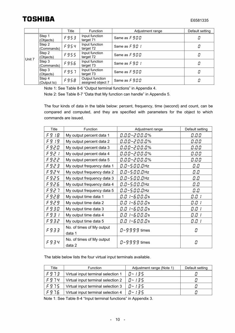
The four kinds of data in the table below: percent, frequency, time (second) and count, can becompared and computed, and they are specified with parameters for the object to whichcommands are issued.
Title Function Adjustment range Default setting
My output percent data 1 ~%
My output percent data 2 ~%
My output percent data 3 ~%
My output percent data 4 ~%
My output percent data 5 ~%
My output frequency data 1 ~Hz
My output frequency data 2 ~Hz
My output frequency data 3 ~Hz
My output frequency data 4 ~Hz
My output frequency data 5 ~Hz
My output time data 1 ~s
My output time data 2 ~s
My output time data 3 ~s
My output time data 4 ~s
My output time data 5 ~s
No. of times of My outputdata 1
~ times
No. of times of My outputdata 2
~ times
The table below lists the four virtual input terminals available.
Title Function Adjustment range (Note 1) Default setting
Virtual input terminal selection 1 ~
Virtual input terminal selection 2 ~
Virtual input terminal selection 3 ~
Virtual input terminal selection 4 ~
Note 1: See Table 8-4 “Input terminal functions” in Appendix 3.
E6581335
- 11 -
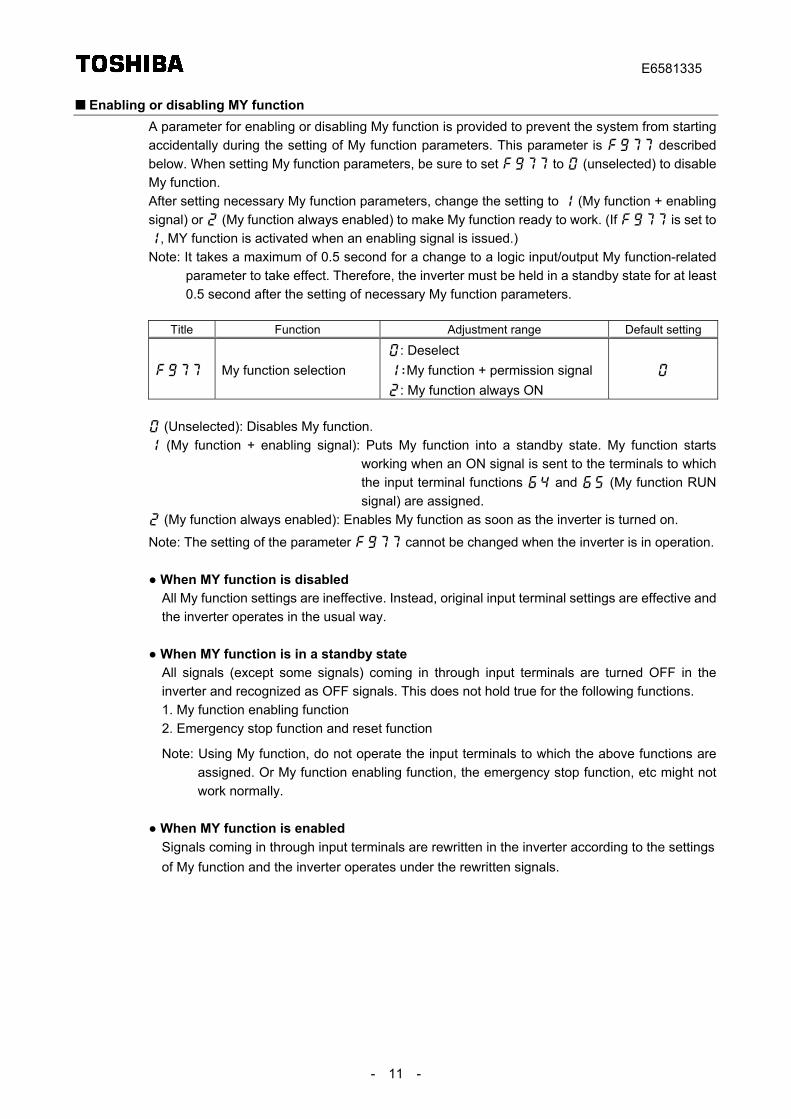
Enabling or disabling MY functionA parameter for enabling or disabling My function is provided to prevent the system from startingaccidentally during the setting of My function parameters. This parameter is describedbelow. When setting My function parameters, be sure to set to (unselected) to disableMy function.After setting necessary My function parameters, change the setting to (My function + enablingsignal) or (My function always enabled) to make My function ready to work. (If is set to, MY function is activated when an enabling signal is issued.)Note: It takes a maximum of 0.5 second for a change to a logic input/output My function-related
parameter to take effect. Therefore, the inverter must be held in a standby state for at least0.5 second after the setting of necessary My function parameters.
Title Function Adjustment range Default setting
My function selection: Deselect: My function + permission signal: My function always ON
(Unselected): Disables My function. (My function + enabling signal): Puts My function into a standby state. My function starts
working when an ON signal is sent to the terminals to whichthe input terminal functions and (My function RUNsignal) are assigned.
(My function always enabled): Enables My function as soon as the inverter is turned on.
Note: The setting of the parameter cannot be changed when the inverter is in operation.
● When MY function is disabledAll My function settings are ineffective. Instead, original input terminal settings are effective andthe inverter operates in the usual way.
● When MY function is in a standby stateAll signals (except some signals) coming in through input terminals are turned OFF in theinverter and recognized as OFF signals. This does not hold true for the following functions.1. My function enabling function2. Emergency stop function and reset function
Note: Using My function, do not operate the input terminals to which the above functions areassigned. Or My function enabling function, the emergency stop function, etc might notwork normally.
● When MY function is enabledSignals coming in through input terminals are rewritten in the inverter according to the settingsof My function and the inverter operates under the rewritten signals.
E6581335
- 12 -
5. Examples of settingThis chapter gives several examples of setting.Note that the settings described below are examples and there are several ways to set a function.Here are the examples of setting given in this chapter.
● Examples of the setting of the combined terminal functionExample 1: Performing the ST+F function by sending a signal to one terminalExample 2: Performing the ST+F+Sr function by sending a signal to one terminalExample 3: Putting out the logical product of a low-speed signal and a low-current signal
● Examples of the setting of the relay sequence functionExample 4: Operation with a combination of 2 input signalsExample 5: Push type operationExample 6: Operation with the automatic stop function
Examples of the setting of the combined terminal function
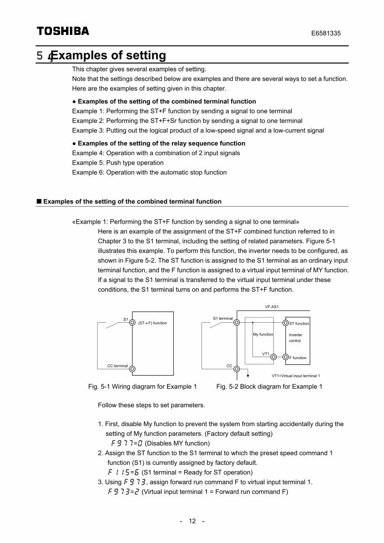
«Example 1: Performing the ST+F function by sending a signal to one terminal»Here is an example of the assignment of the ST+F combined function referred to inChapter 3 to the S1 terminal, including the setting of related parameters. Figure 5-1illustrates this example. To perform this function, the inverter needs to be configured, asshown in Figure 5-2. The ST function is assigned to the S1 terminal as an ordinary inputterminal function, and the F function is assigned to a virtual input terminal of MY function.If a signal to the S1 terminal is transferred to the virtual input terminal under theseconditions, the S1 terminal turns on and performs the ST+F function.
(ST+F) function
CC terminal
S1
Invertercontrol
CC
S1 terminal
F function
VF-AS1
ST function
VT1
VT1=Virtual input terminal 1
My function
Fig. 5-1 Wiring diagram for Example 1 Fig. 5-2 Block diagram for Example 1
Follow these steps to set parameters.
1. First, disable My function to prevent the system from starting accidentally during thesetting of My function parameters. (Factory default setting)
= (Disables MY function)2. Assign the ST function to the S1 terminal to which the preset speed command 1
function (S1) is currently assigned by factory default.= (S1 terminal = Ready for ST operation)
3. Using , assign forward run command F to virtual input terminal 1.= (Virtual input terminal 1 = Forward run command F)
E6581335
- 13 -
4. Then specify commands in accordance with MY function block diagram, and objectsto which the commands are issued.
«Unit 1» Commands ObjectsStep 1 LD = Command for reading S1 terminal
input signalsStep 2 = = Disabling command, because there is
no need to specify this in this example.Step 3 = = Disabling command, because there is
no need to specify this in this example.Step 4 ST = Command for writing signals read in
step 1 to virtual input terminal 1
5. After setting the above My function parameters, set My function ON/OFF selectionparameter to 2 (always enabled) to enable My function.= (My function always enabled)
These settings are summarized in the table below.Title Parameter setting Description
(Default) Disables My function. Assigns the ST terminal function to the S1 terminal.Prior
setting – Assigns the F terminal function to virtual input terminal 1.
Step 1 Reads S1 terminal input signals (LD S1). (Default)
Step 2 (Default)
NOP command (Disabling)
(Default)Step 3
(Default)NOP command (Disabling)
Unit 1
Step 4 Incorporates the result into virtual input terminal 1.
– – Sets My function ON/OFF selection parameter to Alwaysenabled.
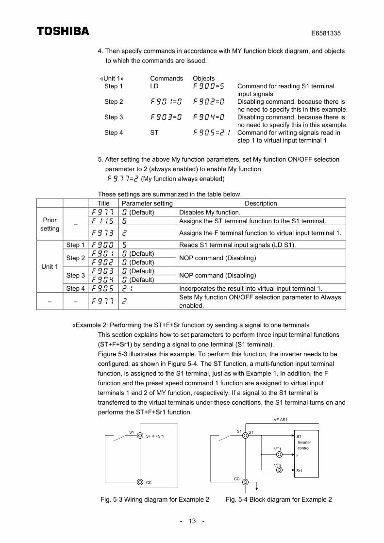
«Example 2: Performing the ST+F+Sr function by sending a signal to one terminal»This section explains how to set parameters to perform three input terminal functions(ST+F+Sr1) by sending a signal to one terminal (S1 terminal).Figure 5-3 illustrates this example. To perform this function, the inverter needs to beconfigured, as shown in Figure 5-4. The ST function, a multi-function input terminalfunction, is assigned to the S1 terminal, just as with Example 1. In addition, the Ffunction and the preset speed command 1 function are assigned to virtual inputterminals 1 and 2 of MY function, respectively. If a signal to the S1 terminal istransferred to the virtual terminals under these conditions, the S1 terminal turns on andperforms the ST+F+Sr1 function.
ST+F+Sr1
CC
S1
Invertercontrol
ST
CC
S1
Sr1
VF-AS1
ST
FVT1
VT2
Fig. 5-3 Wiring diagram for Example 2 Fig. 5-4 Block diagram for Example 2
E6581335
- 14 -
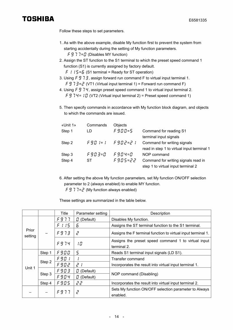
Follow these steps to set parameters.
1. As with the above example, disable My function first to prevent the system fromstarting accidentally during the setting of My function parameters.
= (Disables MY function)2. Assign the ST function to the S1 terminal to which the preset speed command 1
function (S1) is currently assigned by factory default.= (S1 terminal = Ready for ST operation)
3. Using , assign forward run command F to virtual input terminal 1.= (VT1 (Virtual input terminal 1) = Forward run command F)
4. Using , assign preset speed command 1 to virtual input terminal 2.= (VT2 (Virtual input terminal 2) = Preset speed command 1)
5. Then specify commands in accordance with My function block diagram, and objectsto which the commands are issued.
«Unit 1» Commands ObjectsStep 1 LD = Command for reading S1
terminal input signalsStep 2 = = Command for writing signals
read in step 1 to virtual input terminal 1Step 3 = = NOP commandStep 4 ST = Command for writing signals read in
step 1 to virtual input terminal 2
6. After setting the above My function parameters, set My function ON/OFF selectionparameter to 2 (always enabled) to enable MY function.= (My function always enabled)
These settings are summarized in the table below.
Title Parameter setting Description (Default) Disables My function. Assigns the ST terminal function to the S1 terminal.
Assigns the F terminal function to virtual input terminal 1.Prior
setting–
Assigns the preset speed command 1 to virtual inputterminal 2.
Step 1 Reads S1 terminal input signals (LD S1).
Step 2
Transfer commandIncorporates the result into virtual input terminal 1.
(Default)Step 3
(Default)NOP command (Disabling)
Unit 1
Step 4 Incorporates the result into virtual input terminal 2.
– – Sets My function ON/OFF selection parameter to Alwaysenabled.
E6581335
- 15 -
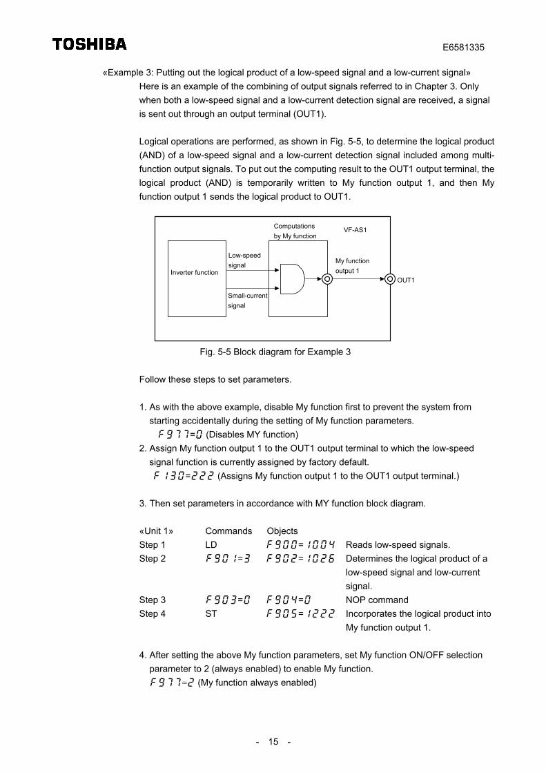
«Example 3: Putting out the logical product of a low-speed signal and a low-current signal»Here is an example of the combining of output signals referred to in Chapter 3. Onlywhen both a low-speed signal and a low-current detection signal are received, a signalis sent out through an output terminal (OUT1).
Logical operations are performed, as shown in Fig. 5-5, to determine the logical product(AND) of a low-speed signal and a low-current detection signal included among multi-function output signals. To put out the computing result to the OUT1 output terminal, thelogical product (AND) is temporarily written to My function output 1, and then Myfunction output 1 sends the logical product to OUT1.
My functionoutput 1
OUT1
Low-speedsignal
Small-currentsignal
Computationsby My function
VF-AS1
Inverter function
Fig. 5-5 Block diagram for Example 3
Follow these steps to set parameters.
1. As with the above example, disable My function first to prevent the system fromstarting accidentally during the setting of My function parameters.
= (Disables MY function)2. Assign My function output 1 to the OUT1 output terminal to which the low-speed
signal function is currently assigned by factory default.= (Assigns My function output 1 to the OUT1 output terminal.)
3. Then set parameters in accordance with MY function block diagram.
«Unit 1» Commands ObjectsStep 1 LD = Reads low-speed signals.Step 2 = = Determines the logical product of a
low-speed signal and low-currentsignal.
Step 3 = = NOP commandStep 4 ST = Incorporates the logical product into
My function output 1.
4. After setting the above My function parameters, set My function ON/OFF selectionparameter to 2 (always enabled) to enable My function.
= (My function always enabled)
E6581335
- 16 -
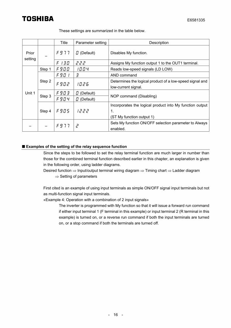
These settings are summarized in the table below.
Title Parameter setting Description
(Default) Disables My function.Priorsetting
–
Assigns My function output 1 to the OUT1 terminal.Step 1 Reads low-speed signals (LD LOW)
AND commandStep 2
Determines the logical product of a low-speed signal andlow-current signal.
(Default)Step 3
(Default)NOP command (Disabling)
Unit 1
Step 4
Incorporates the logical product into My function output1.(ST My function output 1)
– – Sets My function ON/OFF selection parameter to Alwaysenabled.
Examples of the setting of the relay sequence functionSince the steps to be followed to set the relay terminal function are much larger in number thanthose for the combined terminal function described earlier in this chapter, an explanation is givenin the following order, using ladder diagrams.Desired function ⇒ Input/output terminal wiring diagram ⇒ Timing chart ⇒ Ladder diagram
⇒ Setting of parameters
First cited is an example of using input terminals as simple ON/OFF signal input terminals but notas multi-function signal input terminals.«Example 4: Operation with a combination of 2 input signals»
The inverter is programmed with My function so that it will issue a forward run commandif either input terminal 1 (F terminal in this example) or input terminal 2 (R terminal in thisexample) is turned on, or a reverse run command if both the input terminals are turnedon, or a stop command if both the terminals are turned off.
E6581335
- 17 -
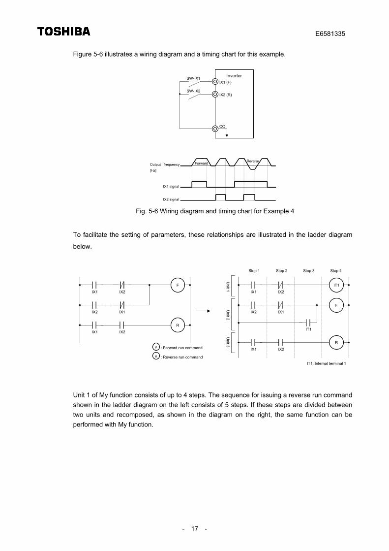
Figure 5-6 illustrates a wiring diagram and a timing chart for this example.
IX1 (F)
CC
IX2 (R)
SW-IX1
SW-IX2
Output frequency[Hz]
IX1 signal
IX2 signal
Forward Reverse
Inverter
Fig. 5-6 Wiring diagram and timing chart for Example 4
To facilitate the setting of parameters, these relationships are illustrated in the ladder diagram
below.
IX2
F
IX1
IX1
IX2
R
IX1 IX2
: Forward run command
: Reverse run command
F
R
Unit 1
Unit 2
Unit 3
F
IX2
IT1
IX1
IX1
IX2
IT1
R
IX1 IX2
IT1: Internal terminal 1
Step 1 Step 2 Step 3 Step 4
Unit 1 of My function consists of up to 4 steps. The sequence for issuing a reverse run commandshown in the ladder diagram on the left consists of 5 steps. If these steps are divided betweentwo units and recomposed, as shown in the diagram on the right, the same function can beperformed with My function.
E6581335
- 18 -
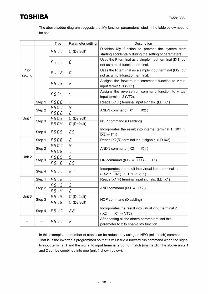
The above ladder diagram suggests that My function parameters listed in the table below need tobe set.
Title Parameter setting Description
(Default)Disables My function to prevent the system fromstarting accidentally during the setting of parameters.
Uses the F terminal as a simple input terminal (IX1) butnot as a multi-function terminal.
Uses the R terminal as a simple input terminal (IX2) butnot as a multi-function terminal.
Assigns the forward run command function to virtualinput terminal 1 (VT1).
Priorsetting
–
Assigns the reverse run command function to virtualinput terminal 2 (VT2).
Step 1 Reads IX1(F) terminal input signals. (LD IX1)
Step 2
ANDN command (IX1 ∩ IX2 )
(Default)Step 3
(Default)NOP command (Disabling)
Unit 1
Step 4 Incorporates the result into internal terminal 1. (IX1 ∩IX2 ⇒ IT1)
Step 1 Reads IX2(R) terminal input signals. (LD IX2)
Step 2
ANDN command (IX2 ∩ IX1 )
Step 3
OR command ((IX2 ∩ IX1) ∪ IT1)
Unit 2
Step 4 Incorporates the result into virtual input terminal 1.((IX2 ∩ IX1) ∪ IT1 ⇒ VT1)
Step 1 Reads IX1(F) terminal input signals. (LD IX1)
Step 2
AND command (IX1 ∩ IX2 )
(Default)Step 3
(Default)NOP command (Disabling)
Unit 3
Step 4 Incorporates the result into virtual input terminal 2.(IX2 ∩ IX1 ⇒ VT2)
– – After setting all the above parameters, set thisparameter to 2 to enable My function.
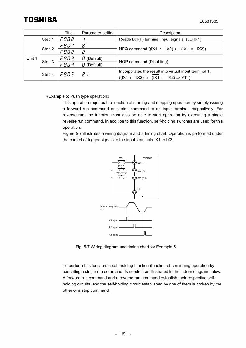
In this example, the number of steps can be reduced by using an NEQ (mismatch) command.That is, if the inverter is programmed so that it will issue a forward run command when the signalto input terminal 1 and the signal to input terminal 2 do not match (mismatch), the above units 1and 2 can be combined into one (unit 1 shown below).
E6581335
- 19 -
Title Parameter setting DescriptionStep 1 Reads IX1(F) terminal input signals. (LD IX1)
Step 2
NEQ command ((IX1 ∩ IX2) ∪ (IX1 ∩ IX2))
(Default)Step 3
(Default)NOP command (Disabling)
Unit 1
Step 4 Incorporates the result into virtual input terminal 1.((IX1 ∩ IX2) ∪ (IX1 ∩ IX2) ⇒ VT1)
«Example 5: Push type operation»This operation requires the function of starting and stopping operation by simply issuinga forward run command or a stop command to an input terminal, respectively. Forreverse run, the function must also be able to start operation by executing a singlereverse run command. In addition to this function, self-holding switches are used for thisoperation.Figure 5-7 illustrates a wiring diagram and a timing chart. Operation is performed underthe control of trigger signals to the input terminals IX1 to IX3.
IX1 (F)
CC
SW-F
IX2 (R)
SW-R
IX3 (S1)
SW-STOP
Inverter
Output frequency[Hz]
IX1 signal
IX2 signal
IX3 signal
Fig. 5-7 Wiring diagram and timing chart for Example 5
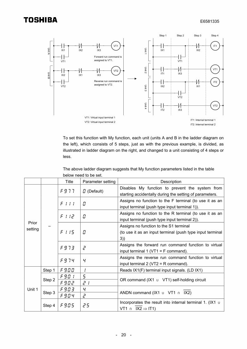
To perform this function, a self-holding function (function of continuing operation byexecuting a single run command) is needed, as illustrated in the ladder diagram below.A forward run command and a reverse run command establish their respective self-holding circuits, and the self-holding circuit established by one of them is broken by theother or a stop command.
E6581335
- 20 -
Unit 2
Unit 3
Unit 4
Unit 1
VT1
IX1 IX3
VT1
IX2
VT2
IX2 IX3
VT2
IX1
Forward run command isassigned to VT1.
Reverse run command isassigned to VT2.
IT2
IX2
VT1
IT1
IX1
IX3
VT2
VT2
IT2 IX3
Step 1 Step 2 Step 3 Step 4
IT1
IX1 IX2
VT1
Unit A
Unit B
VT1: Virtual input terminal 1
VT2: Virtual input terminal 2IT1: Internal terminal 1
IT2: Internal terminal 2
To set this function with My function, each unit (units A and B in the ladder diagram onthe left), which consists of 5 steps, just as with the previous example, is divided, asillustrated in ladder diagram on the right, and changed to a unit consisting of 4 steps orless.
The above ladder diagram suggests that My function parameters listed in the tablebelow need to be set.
Title Parameter setting Description
(Default)Disables My function to prevent the system fromstarting accidentally during the setting of parameters.
Assigns no function to the F terminal (to use it as aninput terminal (push type input terminal 1)).
Assigns no function to the R terminal (to use it as aninput terminal (push type input terminal 2)).
Assigns no function to the S1 terminal(to use it as an input terminal (push type input terminal3))
Assigns the forward run command function to virtualinput terminal 1 (VT1 = F command).
Priorsetting
–
Assigns the reverse run command function to virtualinput terminal 2 (VT2 = R command).
Step 1 Reads IX1(F) terminal input signals. (LD IX1)
Step 2
OR command (IX1 ∪ VT1) self-holding circuit
Step 3
ANDN command (IX1 ∪ VT1 ∩ IX2)
Unit 1
Step 4 Incorporates the result into internal terminal 1. (IX1 ∪VT1 ∩ IX2 ⇒ IT1)
E6581335
- 21 -
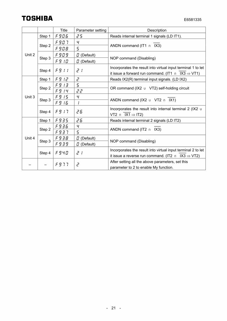
Title Parameter setting DescriptionStep 1 Reads internal terminal 1 signals (LD IT1).
Step 2
ANDN command (IT1 ∩ IX3)
(Default)Step 3
(Default)NOP command (Disabling)
Unit 2
Step 4 Incorporates the result into virtual input terminal 1 to letit issue a forward run command. (IT1 ∩ IX3 ⇒ VT1)
Step 1 Reads IX2(R) terminal input signals. (LD IX2)
Step 2
OR command (IX2 ∪ VT2) self-holding circuit
Step 3
ANDN command (IX2 ∪ VT2 ∩ IX1)
Unit 3
Step 4 Incorporates the result into internal terminal 2 (IX2 ∪VT2 ∩ IX1 ⇒ IT2)
Step 1 Reads internal terminal 2 signals (LD IT2)
Step 2
ANDN command (IT2 ∩ IX3)
(Default)Step 3
(Default)NOP command (Disabling)
Unit 4
Step 4 Incorporates the result into virtual input terminal 2 to letit issue a reverse run command. (IT2 ∩ IX3 ⇒ VT2)
– – After setting all the above parameters, set thisparameter to 2 to enable My function.
E6581335
- 22 -
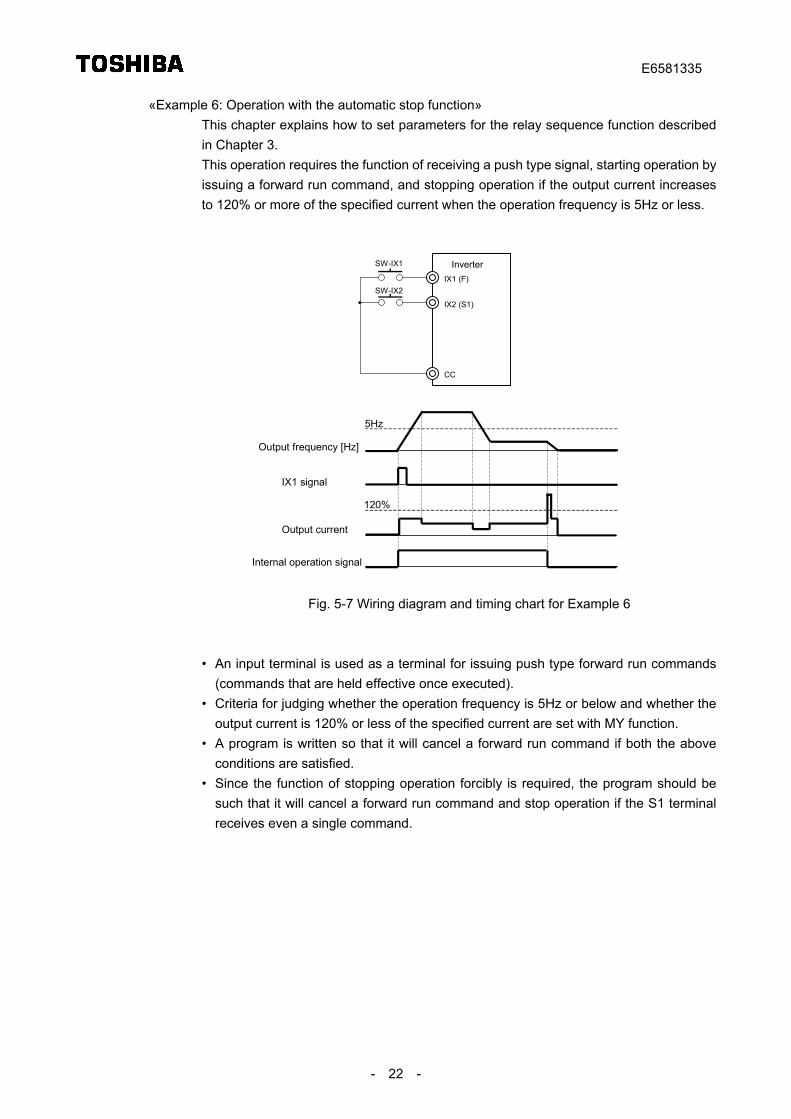
«Example 6: Operation with the automatic stop function»This chapter explains how to set parameters for the relay sequence function describedin Chapter 3.This operation requires the function of receiving a push type signal, starting operation byissuing a forward run command, and stopping operation if the output current increasesto 120% or more of the specified current when the operation frequency is 5Hz or less.
IX1 (F)
CC
SW-IX1
IX2 (S1)
SW-IX2
Inverter
Output frequency [Hz]
Output current
Internal operation signal
5Hz
120%
IX1 signal
Fig. 5-7 Wiring diagram and timing chart for Example 6
• An input terminal is used as a terminal for issuing push type forward run commands(commands that are held effective once executed).
• Criteria for judging whether the operation frequency is 5Hz or below and whether theoutput current is 120% or less of the specified current are set with MY function.
• A program is written so that it will cancel a forward run command if both the aboveconditions are satisfied.
• Since the function of stopping operation forcibly is required, the program should besuch that it will cancel a forward run command and stop operation if the S1 terminalreceives even a single command.
E6581335
- 23 -
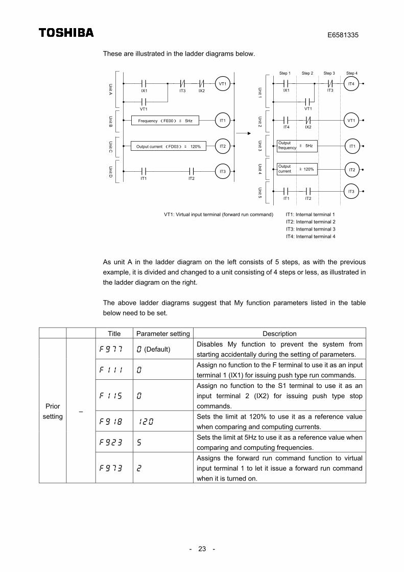
These are illustrated in the ladder diagrams below.
VT1: Virtual input terminal (forward run command) IT1: Internal terminal 1IT2: Internal terminal 2IT3: Internal terminal 3IT4: Internal terminal 4
VT1
Frequency (FE00) ≦ 5Hz
IX1 IT3
VT1
IT1
IT3
IT1 IT2
IT2Output current (FD03) ≧ 120%
Unit A
Unit B
Unit C
Unit D
IX2
IT4IX1 IT3
VT1
VT1
Unit 1
Unit 2
IT4 IX2
Unit 3 IT1
Unit 4
IT3
Unit 5
IT1 IT2
Step 1 Step 2 Step 3 Step 4
IT2
Outputfrequency ≦ 5Hz
Outputcurrent ≧120%
As unit A in the ladder diagram on the left consists of 5 steps, as with the previousexample, it is divided and changed to a unit consisting of 4 steps or less, as illustrated inthe ladder diagram on the right.
The above ladder diagrams suggest that My function parameters listed in the tablebelow need to be set.
Title Parameter setting Description
(Default)Disables My function to prevent the system fromstarting accidentally during the setting of parameters.
Assign no function to the F terminal to use it as an inputterminal 1 (IX1) for issuing push type run commands.
Assign no function to the S1 terminal to use it as aninput terminal 2 (IX2) for issuing push type stopcommands.
Sets the limit at 120% to use it as a reference valuewhen comparing and computing currents.
Sets the limit at 5Hz to use it as a reference value whencomparing and computing frequencies.
Priorsetting
–
Assigns the forward run command function to virtualinput terminal 1 to let it issue a forward run commandwhen it is turned on.
E6581335
- 24 -
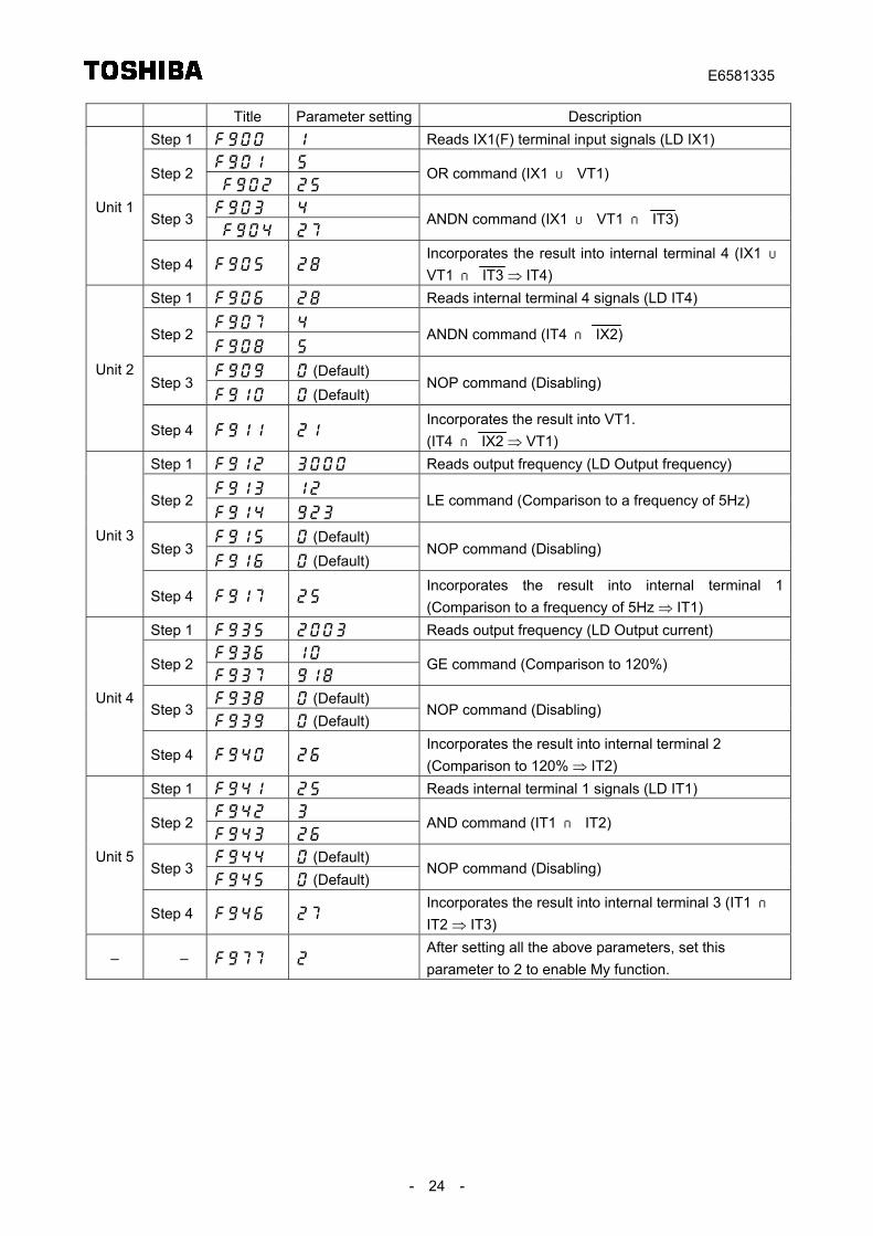
Title Parameter setting DescriptionStep 1 Reads IX1(F) terminal input signals (LD IX1)
Step 2
OR command (IX1 ∪ VT1)
Step 3
ANDN command (IX1 ∪ VT1 ∩ IT3)
Unit 1
Step 4 Incorporates the result into internal terminal 4 (IX1 ∪VT1 ∩ IT3 ⇒ IT4)
Step 1 Reads internal terminal 4 signals (LD IT4)
Step 2
ANDN command (IT4 ∩ IX2)
(Default)Step 3
(Default)NOP command (Disabling)
Unit 2
Step 4 Incorporates the result into VT1.(IT4 ∩ IX2 ⇒ VT1)
Step 1 Reads output frequency (LD Output frequency)
Step 2
LE command (Comparison to a frequency of 5Hz)
(Default)Step 3
(Default)NOP command (Disabling)
Unit 3
Step 4 Incorporates the result into internal terminal 1(Comparison to a frequency of 5Hz ⇒ IT1)
Step 1 Reads output frequency (LD Output current)
Step 2
GE command (Comparison to 120%)
(Default)Step 3
(Default)NOP command (Disabling)
Unit 4
Step 4 Incorporates the result into internal terminal 2(Comparison to 120% ⇒ IT2)
Step 1 Reads internal terminal 1 signals (LD IT1)
Step 2
AND command (IT1 ∩ IT2)
(Default)Step 3
(Default)NOP command (Disabling)
Unit 5
Step 4 Incorporates the result into internal terminal 3 (IT1 ∩IT2 ⇒ IT3)
– – After setting all the above parameters, set thisparameter to 2 to enable My function.
E6581335
- 25 -
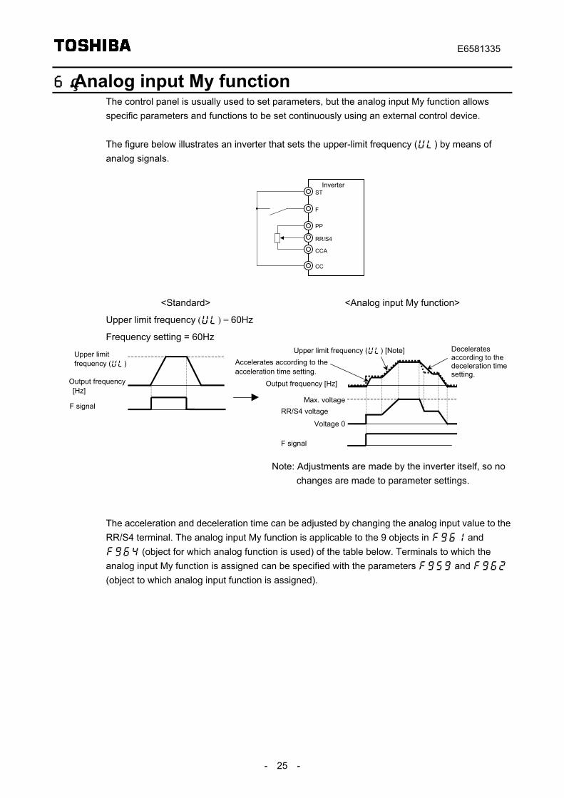
6. Analog input My functionThe control panel is usually used to set parameters, but the analog input My function allowsspecific parameters and functions to be set continuously using an external control device.
The figure below illustrates an inverter that sets the upper-limit frequency () by means ofanalog signals.
ST
F
CC
PP
RR/S4
CCA
Inverter
<Standard> <Analog input My function>
Upper limit frequency () = 60Hz
Frequency setting = 60Hz
Output frequency [Hz]
F signal
Upper limitfrequency ()
Output frequency [Hz]
F signal
Upper limit frequency () [Note]
Max. voltageRR/S4 voltage
Voltage 0
Deceleratesaccording to thedeceleration timesetting.
Accelerates according to theacceleration time setting.
Note: Adjustments are made by the inverter itself, so nochanges are made to parameter settings.
The acceleration and deceleration time can be adjusted by changing the analog input value to theRR/S4 terminal. The analog input My function is applicable to the 9 objects in and (object for which analog function is used) of the table below. Terminals to which theanalog input My function is assigned can be specified with the parameters and (object to which analog input function is assigned).
E6581335
- 26 -
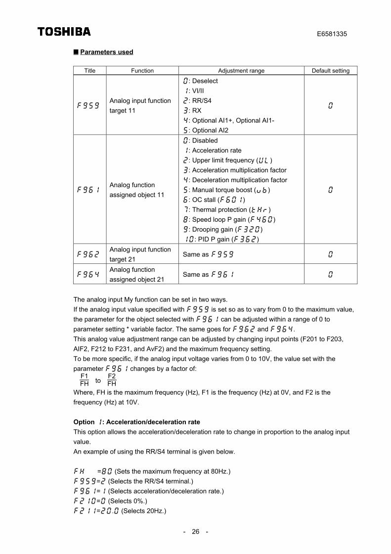
Parameters used
Title Function Adjustment range Default setting
Analog input functiontarget 11
: Deselect: VI/II: RR/S4: RX: Optional AI1+, Optional AI1-: Optional AI2
Analog functionassigned object 11
: Disabled: Acceleration rate: Upper limit frequency (): Acceleration multiplication factor: Deceleration multiplication factor: Manual torque boost (): OC stall (): Thermal protection (): Speed loop P gain (): Drooping gain (): PID P gain ()
Analog input functiontarget 21
Same as
Analog functionassigned object 21
Same as
The analog input My function can be set in two ways.If the analog input value specified with is set so as to vary from 0 to the maximum value,the parameter for the object selected with can be adjusted within a range of 0 toparameter setting * variable factor. The same goes for and .This analog value adjustment range can be adjusted by changing input points (F201 to F203,AIF2, F212 to F231, and AvF2) and the maximum frequency setting.To be more specific, if the analog input voltage varies from 0 to 10V, the value set with theparameter changes by a factor of:
F1FH to
F2FH
Where, FH is the maximum frequency (Hz), F1 is the frequency (Hz) at 0V, and F2 is thefrequency (Hz) at 10V.
Option : Acceleration/deceleration rateThis option allows the acceleration/deceleration rate to change in proportion to the analog inputvalue.An example of using the RR/S4 terminal is given below.
= (Sets the maximum frequency at 80Hz.)= (Selects the RR/S4 terminal.)= (Selects acceleration/deceleration rate.)= (Selects 0%.)=. (Selects 20Hz.)
E6581335
- 27 -
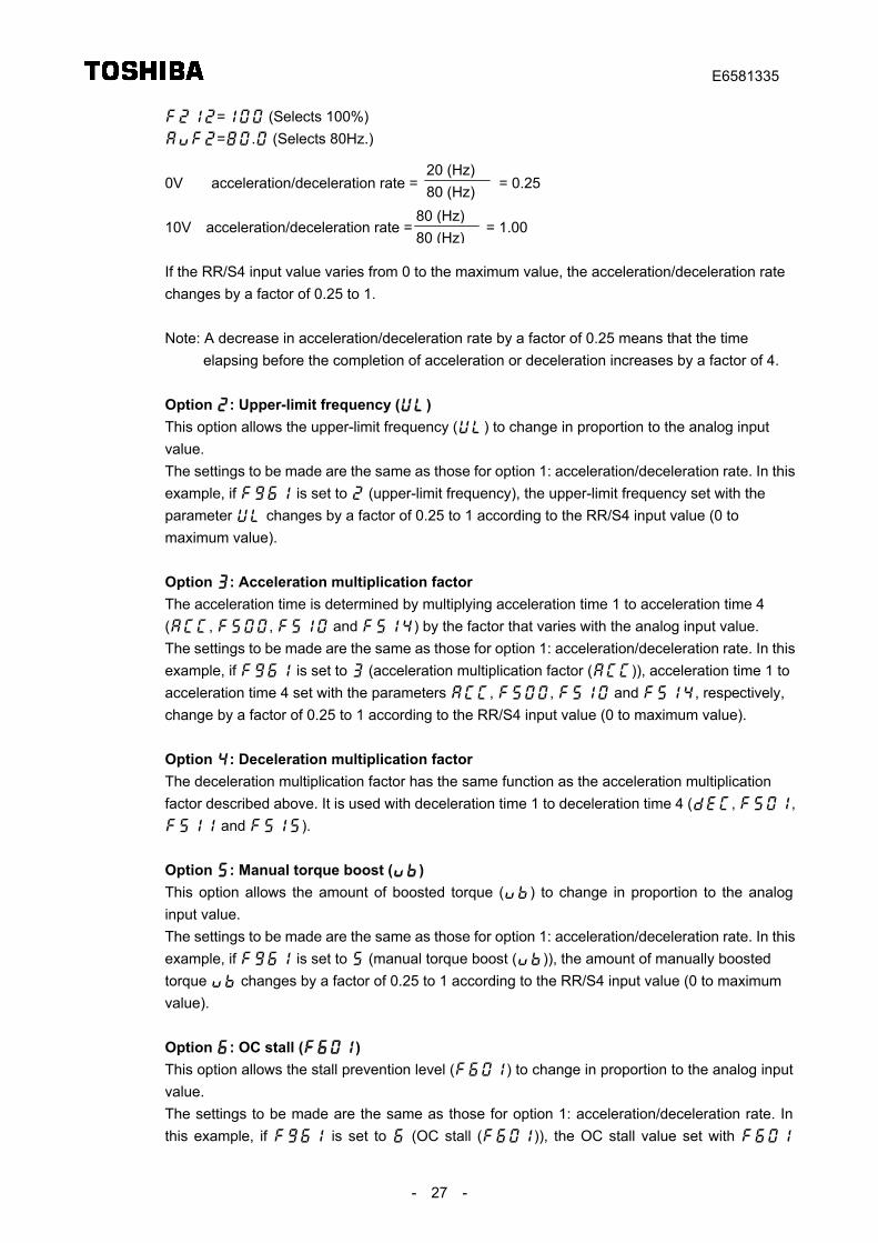
= (Selects 100%)=. (Selects 80Hz.)
0V acceleration/deceleration rate = = 0.25
10V acceleration/deceleration rate = = 1.00
If the RR/S4 input value varies from 0 to the maximum value, the acceleration/deceleration ratechanges by a factor of 0.25 to 1.
Note: A decrease in acceleration/deceleration rate by a factor of 0.25 means that the timeelapsing before the completion of acceleration or deceleration increases by a factor of 4.
Option : Upper-limit frequency ()This option allows the upper-limit frequency () to change in proportion to the analog inputvalue.The settings to be made are the same as those for option 1: acceleration/deceleration rate. In thisexample, if is set to (upper-limit frequency), the upper-limit frequency set with theparameter changes by a factor of 0.25 to 1 according to the RR/S4 input value (0 tomaximum value).
Option : Acceleration multiplication factorThe acceleration time is determined by multiplying acceleration time 1 to acceleration time 4(, , and ) by the factor that varies with the analog input value.The settings to be made are the same as those for option 1: acceleration/deceleration rate. In thisexample, if is set to (acceleration multiplication factor ()), acceleration time 1 toacceleration time 4 set with the parameters , , and , respectively,change by a factor of 0.25 to 1 according to the RR/S4 input value (0 to maximum value).
Option : Deceleration multiplication factorThe deceleration multiplication factor has the same function as the acceleration multiplicationfactor described above. It is used with deceleration time 1 to deceleration time 4 (, , and ).
Option : Manual torque boost ()This option allows the amount of boosted torque () to change in proportion to the analoginput value.The settings to be made are the same as those for option 1: acceleration/deceleration rate. In thisexample, if is set to (manual torque boost ()), the amount of manually boostedtorque changes by a factor of 0.25 to 1 according to the RR/S4 input value (0 to maximumvalue).
Option : OC stall ()This option allows the stall prevention level () to change in proportion to the analog inputvalue.The settings to be made are the same as those for option 1: acceleration/deceleration rate. Inthis example, if is set to (OC stall ()), the OC stall value set with
20 (Hz)80 (Hz)
80 (Hz)80 (Hz)
E6581335
- 28 -
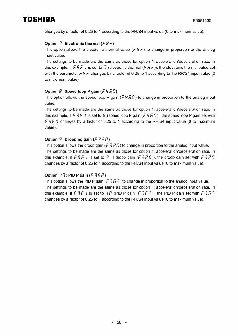
changes by a factor of 0.25 to 1 according to the RR/S4 input value (0 to maximum value).
Option : Electronic thermal ()This option allows the electronic thermal value () to change in proportion to the analoginput value.The settings to be made are the same as those for option 1: acceleration/deceleration rate. Inthis example, if is set to (electronic thermal ()), the electronic thermal value setwith the parameter changes by a factor of 0.25 to 1 according to the RR/S4 input value (0to maximum value).
Option : Speed loop P gain ()This option allows the speed loop P gain () to change in proportion to the analog inputvalue.The settings to be made are the same as those for option 1: acceleration/deceleration rate. Inthis example, if is set to (speed loop P gain ()), the speed loop P gain set with changes by a factor of 0.25 to 1 according to the RR/S4 input value (0 to maximumvalue).
Option : Drooping gain ()This option allows the droop gain () to change in proportion to the analog input value.The settings to be made are the same as those for option 1: acceleration/deceleration rate. Inthis example, if is set to (droop gain ()), the droop gain set with changes by a factor of 0.25 to 1 according to the RR/S4 input value (0 to maximum value).
Option : PID P gain ()This option allows the PID P gain () to change in proportion to the analog input value.The settings to be made are the same as those for option 1: acceleration/deceleration rate. Inthis example, if is set to (PID P gain ()), the PID P gain set with changes by a factor of 0.25 to 1 according to the RR/S4 input value (0 to maximum value).
E6581335
- 29 -
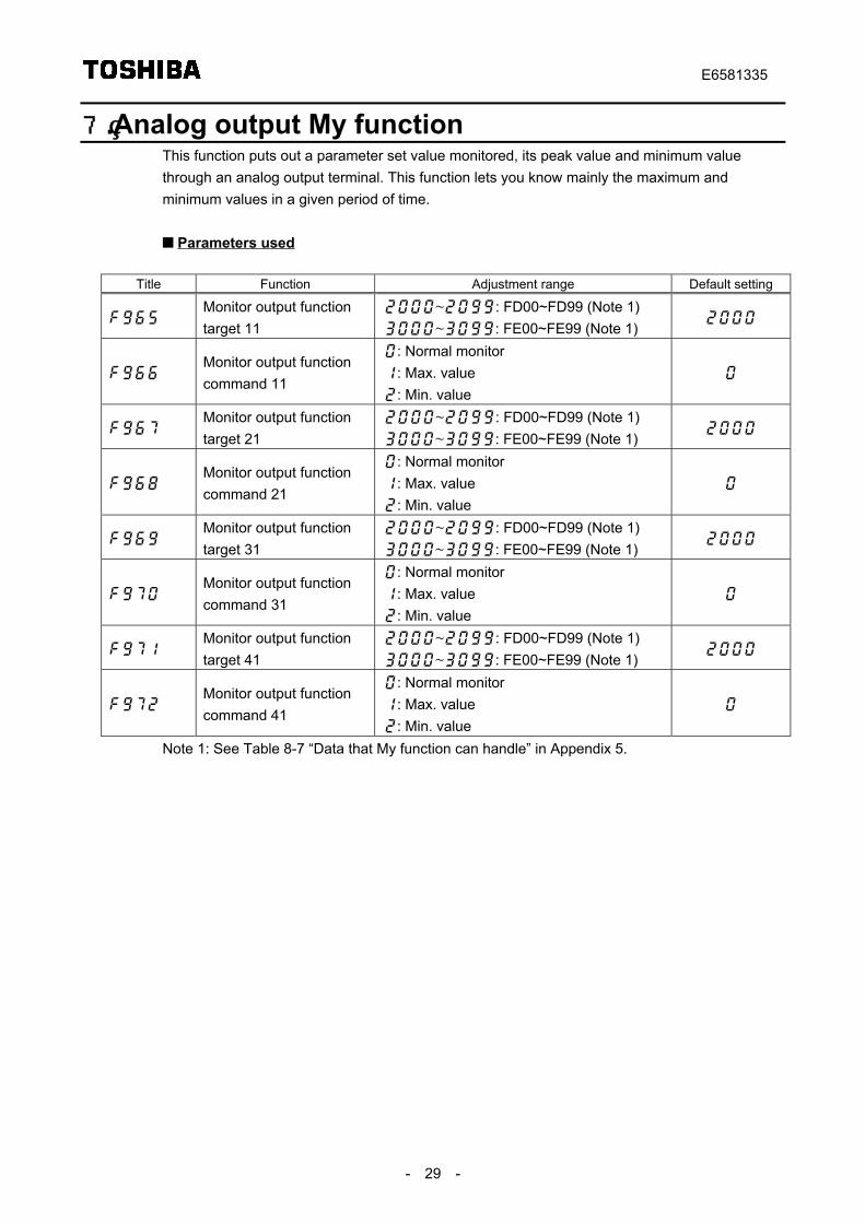
7. Analog output My functionThis function puts out a parameter set value monitored, its peak value and minimum valuethrough an analog output terminal. This function lets you know mainly the maximum andminimum values in a given period of time.
Parameters used
Title Function Adjustment range Default setting
Monitor output functiontarget 11
~: FD00~FD99 (Note 1)~: FE00~FE99 (Note 1)
Monitor output functioncommand 11
: Normal monitor: Max. value: Min. value
Monitor output functiontarget 21
~: FD00~FD99 (Note 1)~: FE00~FE99 (Note 1)
Monitor output functioncommand 21
: Normal monitor: Max. value: Min. value
Monitor output functiontarget 31
~: FD00~FD99 (Note 1)~: FE00~FE99 (Note 1)
Monitor output functioncommand 31
: Normal monitor: Max. value: Min. value
Monitor output functiontarget 41
~: FD00~FD99 (Note 1)~: FE00~FE99 (Note 1)
Monitor output functioncommand 41
: Normal monitor: Max. value: Min. value
Note 1: See Table 8-7 “Data that My function can handle” in Appendix 5.
E6581335
- 30 -
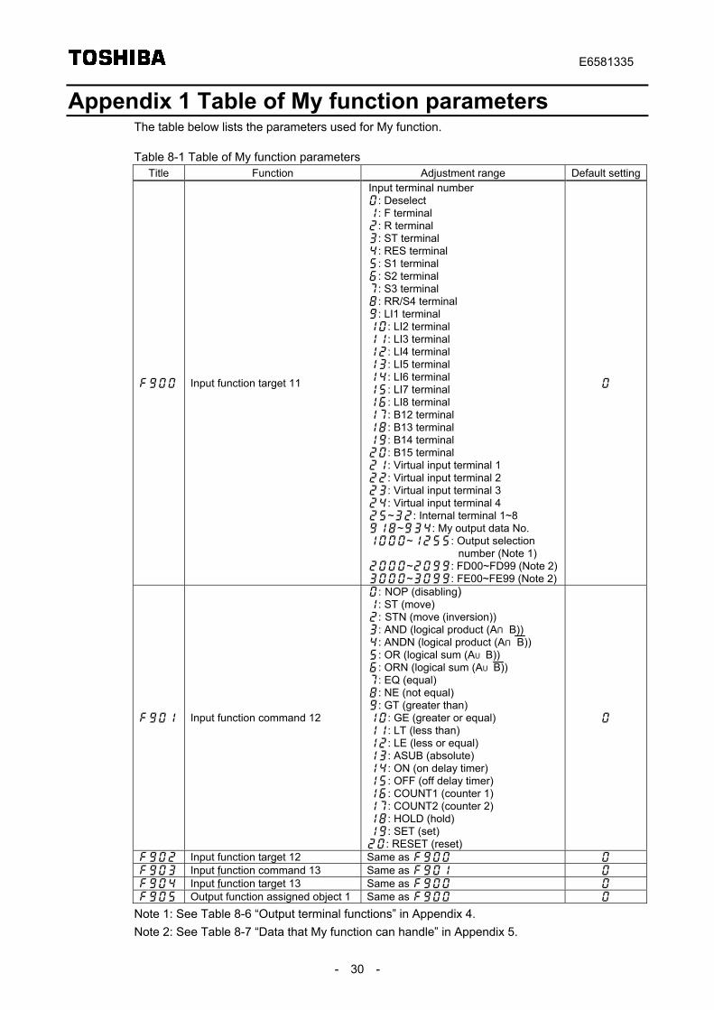
Appendix 1 Table of My function parametersThe table below lists the parameters used for My function.
Table 8-1 Table of My function parametersTitle Function Adjustment range Default setting
Input function target 11
Input terminal number: Deselect: F terminal: R terminal: ST terminal: RES terminal: S1 terminal: S2 terminal: S3 terminal: RR/S4 terminal: LI1 terminal: LI2 terminal: LI3 terminal: LI4 terminal: LI5 terminal: LI6 terminal: LI7 terminal: LI8 terminal: B12 terminal: B13 terminal: B14 terminal: B15 terminal: Virtual input terminal 1: Virtual input terminal 2: Virtual input terminal 3: Virtual input terminal 4~: Internal terminal 1~8~: My output data No.~: Output selection
number (Note 1)~: FD00~FD99 (Note 2)~: FE00~FE99 (Note 2)
Input function command 12
: NOP (disabling): ST (move): STN (move (inversion)): AND (logical product (A∩B)): ANDN (logical product (A∩B)): OR (logical sum (A∪B)): ORN (logical sum (A∪B)): EQ (equal): NE (not equal): GT (greater than): GE (greater or equal): LT (less than): LE (less or equal): ASUB (absolute): ON (on delay timer): OFF (off delay timer): COUNT1 (counter 1): COUNT2 (counter 2): HOLD (hold): SET (set): RESET (reset)
Input function target 12 Same as Input function command 13 Same as Input function target 13 Same as Output function assigned object 1 Same as
Note 1: See Table 8-6 “Output terminal functions” in Appendix 4.Note 2: See Table 8-7 “Data that My function can handle” in Appendix 5.
E6581335
- 31 -
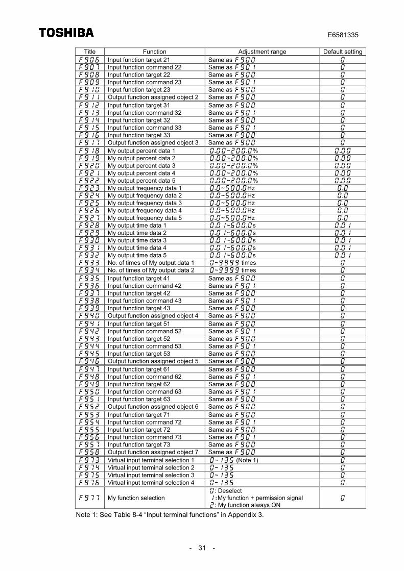
Title Function Adjustment range Default setting Input function target 21 Same as Input function command 22 Same as Input function target 22 Same as Input function command 23 Same as Input function target 23 Same as Output function assigned object 2 Same as
Input function target 31 Same as Input function command 32 Same as Input function target 32 Same as Input function command 33 Same as Input function target 33 Same as Output function assigned object 3 Same as
My output percent data 1 ~% My output percent data 2 ~% My output percent data 3 ~% My output percent data 4 ~% My output percent data 5 ~% My output frequency data 1 ~Hz My output frequency data 2 ~Hz My output frequency data 3 ~Hz My output frequency data 4 ~Hz My output frequency data 5 ~Hz My output time data 1 ~s My output time data 2 ~s My output time data 3 ~s My output time data 4 ~s My output time data 5 ~s No. of times of My output data 1 ~ times No. of times of My output data 2 ~ times
Input function target 41 Same as Input function command 42 Same as Input function target 42 Same as Input function command 43 Same as Input function target 43 Same as Output function assigned object 4 Same as
Input function target 51 Same as Input function command 52 Same as Input function target 52 Same as Input function command 53 Same as Input function target 53 Same as Output function assigned object 5 Same as
Input function target 61 Same as Input function command 62 Same as Input function target 62 Same as Input function command 63 Same as Input function target 63 Same as Output function assigned object 6 Same as
Input function target 71 Same as Input function command 72 Same as Input function target 72 Same as Input function command 73 Same as Input function target 73 Same as Output function assigned object 7 Same as
Virtual input terminal selection 1 ~ (Note 1) Virtual input terminal selection 2 ~ Virtual input terminal selection 3 ~ Virtual input terminal selection 4 ~
My function selection: Deselect: My function + permission signal: My function always ON
Note 1: See Table 8-4 “Input terminal functions” in Appendix 3.
E6581335
- 32 -
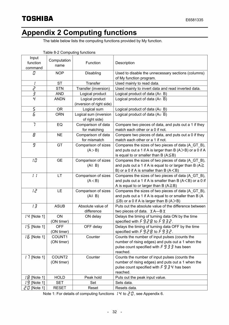
Appendix 2 Computing functionsThe table below lists the computing functions provided by My function.
Table 8-2 Computing functionsInput
functioncommand
Computationname Function Description
NOP Disabling Used to disable the unnecessary sections (columns)of My function program.
ST Transfer Used mainly to read data. STN Transfer (inversion) Used mainly to invert data and read inverted data. AND Logical product Logical product of data (A∩B) ANDN Logical product
(inversion of right side)Logical product of data (A∩B)
OR Logical sum Logical product of data (A∪B) ORN Logical sum (inversion
of right side)Logical product of data (A∪B)
EQ Comparison of datafor matching
Compare two pieces of data, and puts out a 1 if theymatch each other or a 0 if not.
NE Comparison of datafor mismatch
Compare two pieces of data, and puts out a 0 if theymatch each other or a 1 if not.
GT Comparison of sizes(A>B)
Compares the sizes of two pieces of data (A_GT_B),and puts out a 1 if A is larger than B (A>B) or a 0 if Ais equal to or smaller than B (A≦B)
GE Comparison of sizes(A≧B)
Compares the sizes of two pieces of data (A_GT_B),and puts out a 1 if A is equal to or larger than B (A≧B) or a 0 if A is smaller than B (A<B)
LT Comparison of sizes(A<B)
Compares the sizes of two pieces of data (A_GT_B),and puts out a 1 if A is smaller than B (A<B) or a 0 ifA is equal to or larger than B (A≧B)
LE Comparison of sizes(A≦B)
Compares the sizes of two pieces of data (A_GT_B),and puts out a 1 if A is equal to or smaller than B (A≦B) or a 0 if A is larger than B (A>B)
ASUB Absolute value ofdifference
Puts out the absolute value of the difference betweentwo pieces of data. IA―BI
[Note 1] ON(ON timer)
ON delay Delays the timing of turning data ON by the timespecified with to .
[Note 1] OFF(ON timer)
OFF delay Delays the timing of turning data OFF by the timespecified with to .
[Note 1] COUNT1(ON timer)
Counter Counts the number of input pulses (counts thenumber of rising edges) and puts out a 1 when thepulse count specified with has beenreached.
[Note 1] COUNT2(ON timer)
Counter Counts the number of input pulses (counts thenumber of rising edges) and puts out a 1 when thepulse count specified with has beenreached.
[Note 1] HOLD Peak hold Puts out the peak input value. [Note 1] SET Set Sets data. [Note 1] RESET Reset Resets data.
Note 1: For details of computing functions to , see Appendix 6.
E6581335
- 33 -
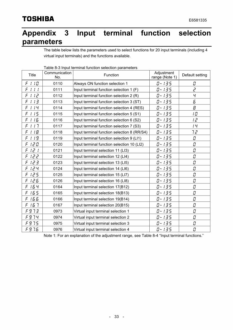
Appendix 3 Input terminal function selectionparameters
The table below lists the parameters used to select functions for 20 input terminals (including 4virtual input terminals) and the functions available.
Table 8-3 Input terminal function selection parameters
Title CommunicationNo. Function Adjustment
range (Note 1) Default setting
0110 Always ON function selection 1 ~
0111 Input terminal function selection 1 (F) ~
0112 Input terminal function selection 2 (R) ~
0113 Input terminal function selection 3 (ST) ~
0114 Input terminal function selection 4 (RES) ~
0115 Input terminal function selection 5 (S1) ~
0116 Input terminal function selection 6 (S2) ~
0117 Input terminal function selection 7 (S3) ~
0118 Input terminal function selection 8 (RR/S4) ~
0119 Input terminal function selection 9 (LI1) ~
0120 Input terminal function selection 10 (LI2) ~
0121 Input terminal selection 11 (LI3) ~
0122 Input terminal selection 12 (LI4) ~
0123 Input terminal selection 13 (LI5) ~
0124 Input terminal selection 14 (LI6) ~
0125 Input terminal selection 15 (LI7) ~
0126 Input terminal selection 16 (LI8) ~
0164 Input terminal selection 17(B12) ~
0165 Input terminal selection 18(B13) ~
0166 Input terminal selection 19(B14) ~
0167 Input terminal selection 20(B15) ~
0973 Virtual input terminal selection 1 ~
0974 Virtual input terminal selection 2 ~
0975 Virtual input terminal selection 3 ~
0976 Virtual input terminal selection 4 ~
Note 1: For an explanation of the adjustment range, see Table 8-4 “Input terminal functions.”
E6581335
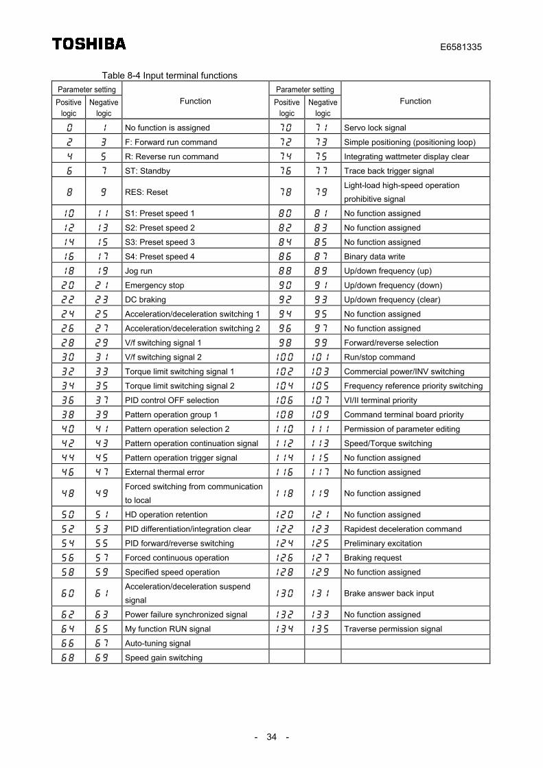
- 34 -
Table 8-4 Input terminal functionsParameter setting Parameter setting
Positivelogic
Negativelogic
Function Positivelogic
Negativelogic
Function
No function is assigned Servo lock signal
F: Forward run command Simple positioning (positioning loop)
R: Reverse run command Integrating wattmeter display clear
ST: Standby Trace back trigger signal
RES: Reset Light-load high-speed operation
prohibitive signal
S1: Preset speed 1 No function assigned
S2: Preset speed 2 No function assigned
S3: Preset speed 3 No function assigned
S4: Preset speed 4 Binary data write
Jog run Up/down frequency (up)
Emergency stop Up/down frequency (down)
DC braking Up/down frequency (clear)
Acceleration/deceleration switching 1 No function assigned
Acceleration/deceleration switching 2 No function assigned
V/f switching signal 1 Forward/reverse selection
V/f switching signal 2 Run/stop command
Torque limit switching signal 1 Commercial power/INV switching
Torque limit switching signal 2 Frequency reference priority switching
PID control OFF selection VI/II terminal priority
Pattern operation group 1 Command terminal board priority
Pattern operation selection 2 Permission of parameter editing
Pattern operation continuation signal Speed/Torque switching
Pattern operation trigger signal No function assigned
External thermal error No function assigned
Forced switching from communication
to local No function assigned
HD operation retention No function assigned
PID differentiation/integration clear Rapidest deceleration command
PID forward/reverse switching Preliminary excitation
Forced continuous operation Braking request
Specified speed operation No function assigned
Acceleration/deceleration suspend
signal Brake answer back input
Power failure synchronized signal No function assigned
My function RUN signal Traverse permission signal
Auto-tuning signal
Speed gain switching
E6581335
- 35 -
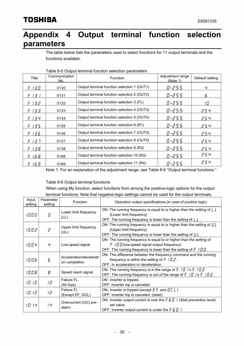
Appendix 4 Output terminal function selectionparameters
The table below lists the parameters used to select functions for 11 output terminals and thefunctions available.
Table 8-5 Output terminal function selection parameters
Title CommunicationNo.
Function Adjustment range(Note 1)
Default setting
0130 Output terminal function selection 1 (OUT1) ~
0131 Output terminal function selection 2 (OUT2) ~
0132 Output terminal function selection 3 (FL) ~
0133 Output terminal function selection 4 (OUT3) ~
0134 Output terminal function selection 5 (OUT4) ~
0135 Output terminal function selection 6 (R1) ~
0136 Output terminal function selection 7 (OUT5) ~
0137 Output terminal function selection 8 (OUT6) ~
0138 Output terminal function selection 9 (R2) ~
0168 Output terminal function selection 10 (R3) ~
0169 Output terminal function selection 11 (R4) ~
Note 1: For an explanation of the adjustment range, see Table 8-6 “Output terminal functions.”
Table 8-6 Output terminal functionsWhen using My function, select functions from among the positive-logic options for the outputterminal functions. Note that negative-logic settings cannot be used for the output terminals.
Inputsetting
Parametersetting Function Operation output specifications (in case of positive logic)
Lower limit frequency(LL)
ON: The running frequency is equal to or higher than the setting of (Lower limit frequency)
OFF: The running frequency is lower than the setting of .
Upper limit frequency(UL)
ON: The running frequency is equal to or higher than the setting of (Upper limit frequency)
OFF: The running frequency is lower than the setting of .
Low-speed signalON: The running frequency is equal to or higher than the setting of
(low-speed signal output frequency)OFF: The running frequency is lower than the setting of .
Acceleration/deceleration completion
ON: The difference between the frequency command and the runningfrequency is within the setting of .
OFF: In acceleration or deceleration.
Speed reach signalON: The running frequency is in the range of ± .OFF: The running frequency is out of the range of ± .
Failure FL(All trips)
ON: Inverter is tripped.OFF: Inverter trip is canceled.
Failure FL(Except EF, OCL)
ON: Inverter is tripped (except and )OFF: Inverter trip is canceled. (reset)
Overcurrent (OC) pre-alarm
ON: Inverter output current is over the (Stall prevention level)set value.
OFF: Inverter output current is under the .
E6581335
- 36 -
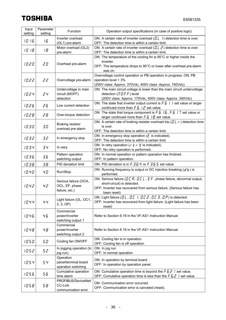
Inputsetting
Parametersetting Function Operation output specifications (in case of positive logic)
Inverter overload(OL1) pre-alarm
ON: A certain rate of inverter overload () detection time is over.OFF: The detection time is within a certain limit.
Motor overload (OL2)pre-alarm
ON: A certain rate of inverter overload () detection time is over.OFF: The detection time is within a certain limit.
Overheat pre-alarm
ON: The temperature of the cooling fin is 95°C or higher inside theinverter.
OFF: The temperature drops to 90°C or lower after overheat pre-alarmwas on.
Overvoltage pre-alarmOvervoltage control operation or PB operation in progress. ON: PBoperation level + 3%(200V class: Approx. 370Vdc, 400V class :Approx. 740Vdc)
Undervoltage in maincircuit (MOFF)detection
ON: The main circuit voltage is lower than the main circuit undervoltagedetection () level.(200V class: Approx. 170Vdc, 400V class: Approx. 340Vdc)
Low current detectionON: The state that inverter output current is set value or larger
continued more than set value.
Over-torque detectionON: The state that torque component is , set value or
larger continued more than set value.
Braking resistoroverload pre-alarm
ON: A certain rate of braking resister overload trip () detection timeis over.
OFF: The detection time is within a certain limit.
In emergency stopON: In emergency stop operation ( is indicated).OFF: The detection time is within a certain limit.
In retryON: In retry operation ( is indicated).OFF: No retry operation is performed.
Pattern operationswitching output
ON: In normal operation or pattern operation has finished.OFF: In pattern operation.
PID deviation limit ON: PID deviation is in or set value.
Run/StopON: Running frequency is output or DC injection breaking () is
performed.
Serious failure (OCA,OCL, EF, phasefailure, etc.)
ON: Serious failure (, , , phase failure, abnormal output,short-circuit) is detected.
OFF: Inverter has recovered from serious failure. (Serious failure hasbeen reset)
Light failure (OL, OC1,2, 3, OP)
ON: Light failure (, , , , ) is detected.OFF: Inverter has recovered from light failure. (Light failure has been
reset)
Commercialpower/inverterswitching output 1
Refer to Section 6.19 in the VF-AS1 Instruction Manual.
Commercialpower/inverterswitching output 2
Refer to Section 6.19 in the VF-AS1 Instruction Manual.
Cooling fan ON/OFFON: Cooling fan is in operation.OFF: Cooling fan is off operation.
In jogging operation (Injog run)
ON: In jog runOFF: In normal operation
Operationpanel/terminal boardoperation switching
ON: In operation by terminal board.OFF: In operation by operation panel.
Cumulative operationtime alarm
ON: Cumulative operation time is beyond the set value.OFF: Cumulative operation time is less than the set value.
PROFIBUS/DeviceNet/CC-Linkcommunication error
ON: Communication error occurred.OFF: Communication error is canceled (reset).
E6581335
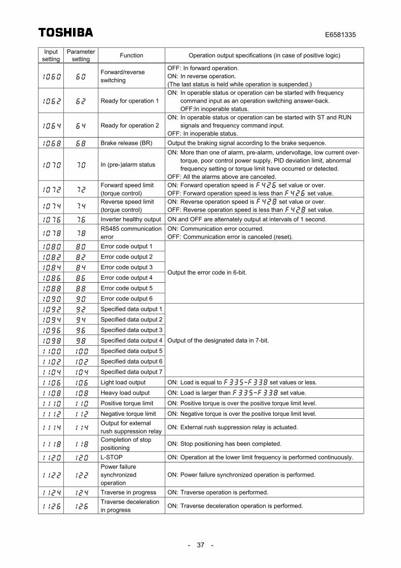
- 37 -
Inputsetting
Parametersetting Function Operation output specifications (in case of positive logic)
Forward/reverseswitching
OFF: In forward operation.ON: In reverse operation.(The last status is held while operation is suspended.)
Ready for operation 1ON: In operable status or operation can be started with frequency
command input as an operation switching answer-back.OFF:In inoperable status.
Ready for operation 2ON: In operable status or operation can be started with ST and RUN
signals and frequency command input.OFF: In inoperable status.
Brake release (BR) Output the braking signal according to the brake sequence.
In (pre-)alarm status
ON: More than one of alarm, pre-alarm, undervoltage, low current over-torque, poor control power supply, PID deviation limit, abnormalfrequency setting or torque limit have occurred or detected.
OFF: All the alarms above are canceled.
Forward speed limit(torque control)
ON: Forward operation speed is set value or over.OFF: Forward operation speed is less than set value.
Reverse speed limit(torque control)
ON: Reverse operation speed is set value or over.OFF: Reverse operation speed is less than set value.
Inverter healthy output ON and OFF are alternately output at intervals of 1 second.
RS485 communicationerror
ON: Communication error occurred.OFF: Communication error is canceled (reset).
Error code output 1
Error code output 2
Error code output 3
Error code output 4
Error code output 5
Error code output 6
Output the error code in 6-bit.
Specified data output 1
Specified data output 2
Specified data output 3
Specified data output 4
Specified data output 5
Specified data output 6
Specified data output 7
Output of the designated data in 7-bit.
Light load output ON: Load is equal to ~ set values or less.
Heavy load output ON: Load is larger than ~ set value.
Positive torque limit ON: Positive torque is over the positive torque limit level.
Negative torque limit ON: Negative torque is over the positive torque limit level.
Output for externalrush suppression relay
ON: External rush suppression relay is actuated.
Completion of stoppositioning
ON: Stop positioning has been completed.
L-STOP ON: Operation at the lower limit frequency is performed continuously.
Power failuresynchronizedoperation
ON: Power failure synchronized operation is performed.
Traverse in progress ON: Traverse operation is performed.
Traverse decelerationin progress
ON: Traverse deceleration operation is performed.
E6581335
- 38 -
Inputsetting
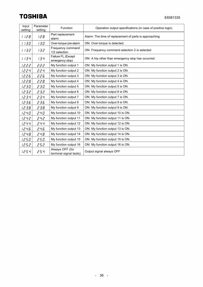
Parametersetting Function Operation output specifications (in case of positive logic)
Part replacementalarm
Alarm: The time of replacement of parts is approaching.
Over-torque pre-alarm ON: Over-torque is detected.
Frequency command1/2 selection
ON: Frequency command selection 2 is selected.
Failure FL (Exceptemergency stop)
ON: A trip other than emergency stop has occurred.
My function output 1 ON: My function output 1 is ON.
My function output 2 ON: My function output 2 is ON.
My function output 3 ON: My function output 3 is ON.
My function output 4 ON: My function output 4 is ON.
My function output 5 ON: My function output 5 is ON.
My function output 6 ON: My function output 6 is ON.
My function output 7 ON: My function output 7 is ON.
My function output 8 ON: My function output 8 is ON.
My function output 9 ON: My function output 9 is ON.
My function output 10 ON: My function output 10 is ON.
My function output 11 ON: My function output 11 is ON.
My function output 12 ON: My function output 12 is ON.
My function output 13 ON: My function output 13 is ON.
My function output 14 ON: My function output 14 is ON.
My function output 15 ON: My function output 15 is ON.
My function output 16 ON: My function output 16 is ON.
Always OFF (forterminal signal tests)
Output signal always OFF
E6581335
- 39 -
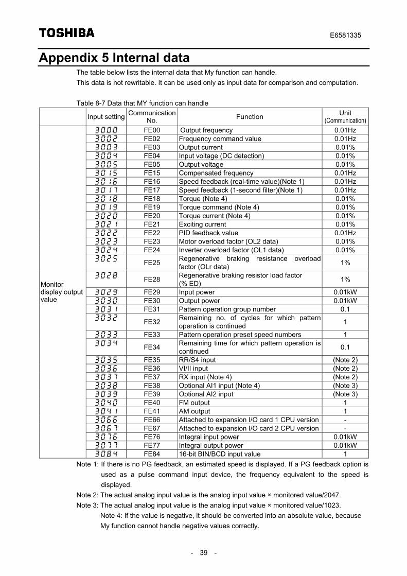
Appendix 5 Internal dataThe table below lists the internal data that My function can handle.This data is not rewritable. It can be used only as input data for comparison and computation.
Table 8-7 Data that MY function can handle
Input setting CommunicationNo. Function Unit
(Communication) FE00 Output frequency 0.01Hz FE02 Frequency command value 0.01Hz FE03 Output current 0.01% FE04 Input voltage (DC detection) 0.01% FE05 Output voltage 0.01% FE15 Compensated frequency 0.01Hz FE16 Speed feedback (real-time value)(Note 1) 0.01Hz FE17 Speed feedback (1-second filter)(Note 1) 0.01Hz FE18 Torque (Note 4) 0.01% FE19 Torque command (Note 4) 0.01% FE20 Torque current (Note 4) 0.01% FE21 Exciting current 0.01% FE22 PID feedback value 0.01Hz FE23 Motor overload factor (OL2 data) 0.01% FE24 Inverter overload factor (OL1 data) 0.01% FE25 Regenerative braking resistance overload
factor (OLr data) 1%
FE28 Regenerative braking resistor load factor(% ED) 1%
FE29 Input power 0.01kW FE30 Output power 0.01kW FE31 Pattern operation group number 0.1 FE32 Remaining no. of cycles for which pattern
operation is continued 1
FE33 Pattern operation preset speed numbers 1 FE34 Remaining time for which pattern operation is
continued 0.1
FE35 RR/S4 input (Note 2) FE36 VI/II input (Note 2) FE37 RX input (Note 4) (Note 2) FE38 Optional AI1 input (Note 4) (Note 3) FE39 Optional AI2 input (Note 3) FE40 FM output 1 FE41 AM output 1 FE66 Attached to expansion I/O card 1 CPU version - FE67 Attached to expansion I/O card 2 CPU version - FE76 Integral input power 0.01kW FE77 Integral output power 0.01kW
Monitordisplay outputvalue
FE84 16-bit BIN/BCD input value 1Note 1: If there is no PG feedback, an estimated speed is displayed. If a PG feedback option is
used as a pulse command input device, the frequency equivalent to the speed isdisplayed.
Note 2: The actual analog input value is the analog input value × monitored value/2047.Note 3: The actual analog input value is the analog input value × monitored value/1023.
Note 4: If the value is negative, it should be converted into an absolute value, becauseMy function cannot handle negative values correctly.
E6581335
- 40 -
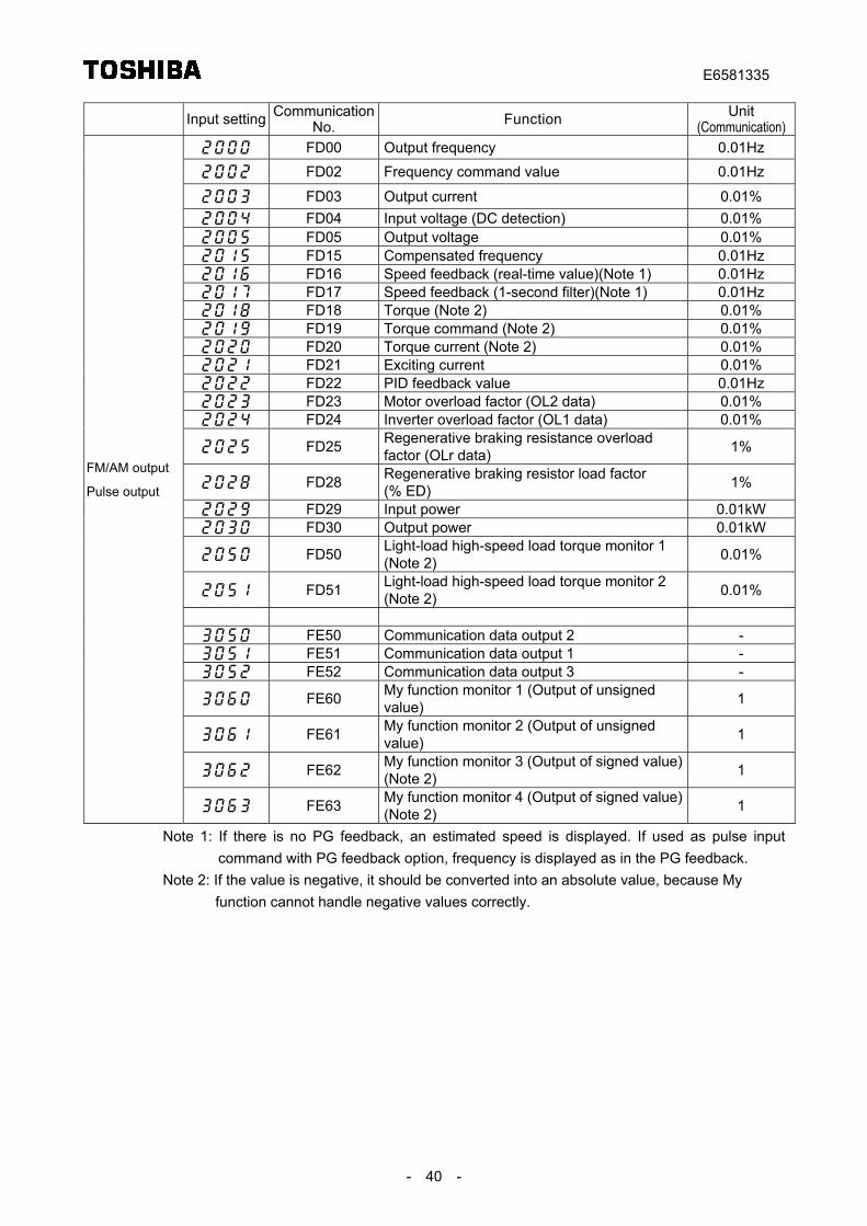
Input setting CommunicationNo. Function Unit
(Communication) FD00 Output frequency 0.01Hz FD02 Frequency command value 0.01Hz
FD03 Output current 0.01% FD04 Input voltage (DC detection) 0.01% FD05 Output voltage 0.01% FD15 Compensated frequency 0.01Hz FD16 Speed feedback (real-time value)(Note 1) 0.01Hz FD17 Speed feedback (1-second filter)(Note 1) 0.01Hz FD18 Torque (Note 2) 0.01% FD19 Torque command (Note 2) 0.01% FD20 Torque current (Note 2) 0.01% FD21 Exciting current 0.01% FD22 PID feedback value 0.01Hz FD23 Motor overload factor (OL2 data) 0.01% FD24 Inverter overload factor (OL1 data) 0.01%
FD25 Regenerative braking resistance overloadfactor (OLr data) 1%
FD28 Regenerative braking resistor load factor(% ED) 1%
FD29 Input power 0.01kW FD30 Output power 0.01kW
FD50 Light-load high-speed load torque monitor 1(Note 2) 0.01%
FD51 Light-load high-speed load torque monitor 2(Note 2) 0.01%
FE50 Communication data output 2 - FE51 Communication data output 1 - FE52 Communication data output 3 -
FE60 My function monitor 1 (Output of unsignedvalue) 1
FE61 My function monitor 2 (Output of unsignedvalue) 1
FE62 My function monitor 3 (Output of signed value)(Note 2) 1
FM/AM output
Pulse output
FE63 My function monitor 4 (Output of signed value)(Note 2) 1
Note 1: If there is no PG feedback, an estimated speed is displayed. If used as pulse inputcommand with PG feedback option, frequency is displayed as in the PG feedback.
Note 2: If the value is negative, it should be converted into an absolute value, because Myfunction cannot handle negative values correctly.
E6581335
- 41 -
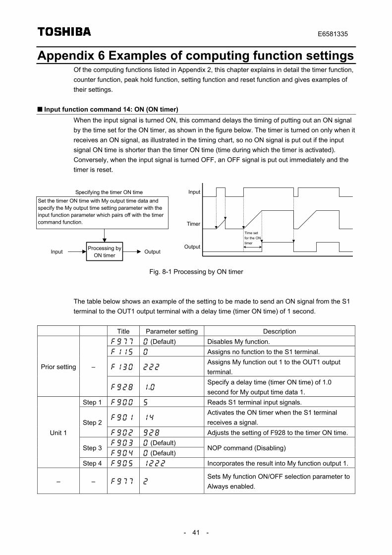
Appendix 6 Examples of computing function settingsOf the computing functions listed in Appendix 2, this chapter explains in detail the timer function,counter function, peak hold function, setting function and reset function and gives examples oftheir settings.
Input function command 14: ON (ON timer)When the input signal is turned ON, this command delays the timing of putting out an ON signalby the time set for the ON timer, as shown in the figure below. The timer is turned on only when itreceives an ON signal, as illustrated in the timing chart, so no ON signal is put out if the inputsignal ON time is shorter than the timer ON time (time during which the timer is activated).Conversely, when the input signal is turned OFF, an OFF signal is put out immediately and thetimer is reset.
Fig. 8-1 Processing by ON timer
The table below shows an example of the setting to be made to send an ON signal from the S1terminal to the OUT1 output terminal with a delay time (timer ON time) of 1 second.
Title Parameter setting Description (Default) Disables My function. Assigns no function to the S1 terminal.
Assigns My function out 1 to the OUT1 outputterminal.
Prior setting –
Specify a delay time (timer ON time) of 1.0second for My output time data 1.
Step 1 Reads S1 terminal input signals.
Activates the ON timer when the S1 terminalreceives a signal.Step 2
Adjusts the setting of F928 to the timer ON time. (Default)
Step 3 (Default)
NOP command (Disabling)
Unit 1
Step 4 Incorporates the result into My function output 1.
– – Sets My function ON/OFF selection parameter toAlways enabled.
Input
Output
TimerTime setfor the ONtimer
Processing byON timer
Set the timer ON time with My output time data andspecify the My output time setting parameter with theinput function parameter which pairs off with the timercommand function.
Input Output
Specifying the timer ON time
E6581335
- 42 -
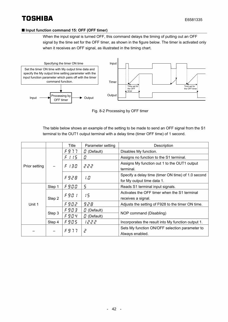
Input function command 15: OFF (OFF timer)When the input signal is turned OFF, this command delays the timing of putting out an OFFsignal by the time set for the OFF timer, as shown in the figure below. The timer is activated onlywhen it receives an OFF signal, as illustrated in the timing chart.
Fig. 8-2 Processing by OFF timer
The table below shows an example of the setting to be made to send an OFF signal from the S1terminal to the OUT1 output terminal with a delay time (timer OFF time) of 1 second.
Title Parameter setting Description (Default) Disables My function. Assigns no function to the S1 terminal.
Assigns My function out 1 to the OUT1 outputterminal.
Prior setting –
Specify a delay time (timer ON time) of 1.0 secondfor My output time data 1.
Step 1 Reads S1 terminal input signals.
Activates the OFF timer when the S1 terminalreceives a signal.Step 2
Adjusts the setting of F928 to the timer ON time. (Default)
Step 3 (Default)
NOP command (Disabling)
Unit 1
Step 4 Incorporates the result into My function output 1.
– – Sets My function ON/OFF selection parameter toAlways enabled.
Input
Output
TimerTime set forthe OFFtimer
Time set forthe OFF timer
Processing byOFF timer
Set the timer ON time with My output time data andspecify the My output time setting parameter with theinput function parameter which pairs off with the timer
command function.
Input Output
Specifying the timer ON time
E6581335
- 43 -
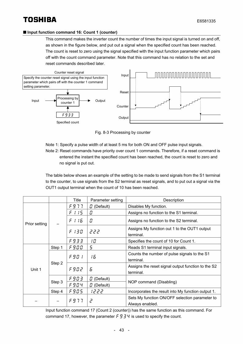
Input function command 16: Count 1 (counter)This command makes the inverter count the number of times the input signal is turned on and off,as shown in the figure below, and put out a signal when the specified count has been reached.The count is reset to zero using the signal specified with the input function parameter which pairsoff with the count command parameter. Note that this command has no relation to the set andreset commands described later.
Fig. 8-3 Processing by counter
Note 1: Specify a pulse width of at least 5 ms for both ON and OFF pulse input signals.Note 2: Reset commands have priority over count 1 commands. Therefore, if a reset command is
entered the instant the specified count has been reached, the count is reset to zero andno signal is put out.
The table below shows an example of the setting to be made to send signals from the S1 terminalto the counter, to use signals from the S2 terminal as reset signals, and to put out a signal via theOUT1 output terminal when the count of 10 has been reached.
Title Parameter setting Description (Default) Disables My function. Assigns no function to the S1 terminal.
Assigns no function to the S2 terminal.
Assigns My function out 1 to the OUT1 outputterminal.
Prior setting –
Specifies the count of 10 for Count 1.Step 1 Reads S1 terminal input signals.
Counts the number of pulse signals to the S1terminal.
Step 2
Assigns the reset signal output function to the S2terminal.
(Default)Step 3
(Default)NOP command (Disabling)
Unit 1
Step 4 Incorporates the result into My function output 1.
– – Sets My function ON/OFF selection parameter toAlways enabled.
Input function command 17 (Count 2 (counter)) has the same function as this command. Forcommand 17, however, the parameter is used to specify the count.
0
Processing bycounter 1
Specify the counter reset signal using the input functionparameter which pairs off with the counter 1 commandsetting parameter.
Input Output
Counter reset signalInput
Output
Counter
Specified count
Reset
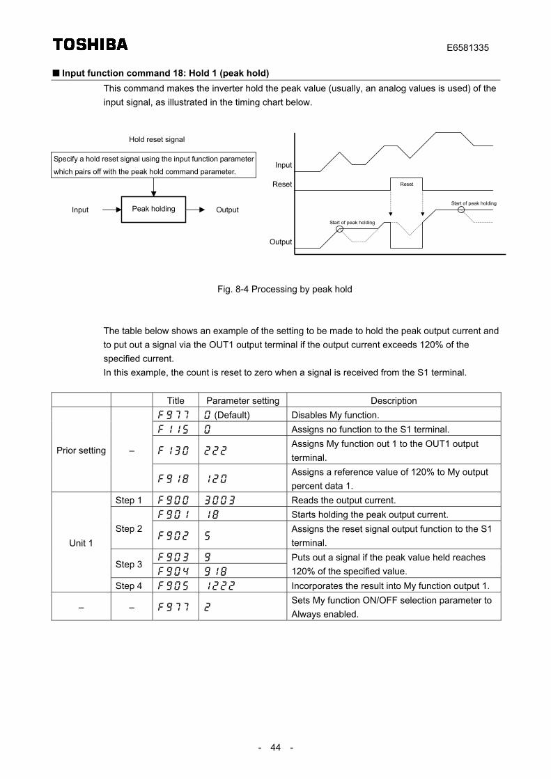
E6581335
- 44 -
Input function command 18: Hold 1 (peak hold)This command makes the inverter hold the peak value (usually, an analog values is used) of theinput signal, as illustrated in the timing chart below.
Fig. 8-4 Processing by peak hold
The table below shows an example of the setting to be made to hold the peak output current andto put out a signal via the OUT1 output terminal if the output current exceeds 120% of thespecified current.In this example, the count is reset to zero when a signal is received from the S1 terminal.
Title Parameter setting Description (Default) Disables My function. Assigns no function to the S1 terminal.
Assigns My function out 1 to the OUT1 outputterminal.
Prior setting –
Assigns a reference value of 120% to My outputpercent data 1.
Step 1 Reads the output current. Starts holding the peak output current.
Step 2
Assigns the reset signal output function to the S1terminal.
Step 3
Puts out a signal if the peak value held reaches120% of the specified value.
Unit 1
Step 4 Incorporates the result into My function output 1.
– – Sets My function ON/OFF selection parameter toAlways enabled.
Peak holding
Specify a hold reset signal using the input function parameter
which pairs off with the peak hold command parameter.
Input Output
Hold reset signal
Input
Output
Reset
Start of peak holding
Start of peak holding
Reset
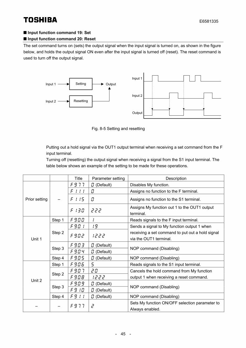
E6581335
- 45 -
Input function command 19: Set Input function command 20: Reset
The set command turns on (sets) the output signal when the input signal is turned on, as shown in the figurebelow, and holds the output signal ON even after the input signal is turned off (reset). The reset command isused to turn off the output signal.
Fig. 8-5 Setting and resetting
Putting out a hold signal via the OUT1 output terminal when receiving a set command from the Finput terminal.Turning off (resetting) the output signal when receiving a signal from the S1 input terminal. Thetable below shows an example of the setting to be made for these operations.
Title Parameter setting Description (Default) Disables My function. Assigns no function to the F terminal.
Assigns no function to the S1 terminal.Prior setting –
Assigns My function out 1 to the OUT1 outputterminal.
Step 1 Reads signals to the F input terminal.
Step 2
Sends a signal to My function output 1 whenreceiving a set command to put out a hold signalvia the OUT1 terminal.
(Default)Step 3
(Default)NOP command (Disabling)
Unit 1
Step 4 (Default) NOP command (Disabling)Step 1 Reads signals to the S1 input terminal.
Step 2
Cancels the hold command from My functionoutput 1 when receiving a reset command.
(Default)Step 3
(Default)NOP command (Disabling)
Unit 2
Step 4 (Default) NOP command (Disabling)
– – Sets My function ON/OFF selection parameter toAlways enabled.
SettingInput 1 Output
Input 1
Output
Input 2ResettingInput 2
Recommended


![Input Function x(t) Output Function y(t) T[ ]. Consider The following Input/Output relations](https://img.pdfslide.net/doc/110x75/56649f4a5503460f94c6c48c/input-function-xt-output-function-yt-t-consider-the-following-inputoutput.jpg)