2AZ-FE ENGINE MECHANICAL – ENGINE EM–1
M
EENGINEINSPECTION1. INSPECT ENGINE COOLANT
(a) Inspect the engine coolant (See page CO-1).
2. INSPECT ENGINE OIL(a) Inspect the engine oil (See page LU-1).
3. INSPECT BATTERY(a) Inspect the battery (See page CH-4).
4. INSPECT SPARK PLUGS(a) Inspect the spark plugs (See page IG-5).
5. INSPECT AIR CLEANER FILTER ELEMENT SUB-ASSEMBLY(a) Remove the air cleaner filter element sub-assembly.(b) Visually check that there is no dirt, blockage, and/or
damage to the air cleaner filter element.HINT:• If there is any dirt or a blockage in the air cleaner
filter element, clean it with compressed air.• If any dirt or a blockage remains even after
cleaning the air cleaner filter element with compressed air, replace it.
6. INSPECT IGNITION TIMING(a) Warm up the engine.(b) When using the intelligent tester:
Check the ignition timing.(1) Connect the intelligent tester to the DLC3.(2) Enter DATA LIST MODE on the intelligent
tester.Ignition timing:
8 to 12° BTDC at idleHINT:Refer to the intelligent tester operator's manual for help when selecting the DATA LIST.
(c) When not using the intelligent tester:Check the ignition timing.(1) Using SST, connect terminals 13 (TC) and 4
(CG) of the DLC3.SST 09843-18040NOTICE:• Confirm the terminal numbers before
connecting them. Connection with a wrong terminal can damage the engine.
• Turn off all electrical systems before connecting the terminals.
• Perform this inspection after the cooling fan motor is turned off.
Intelligent Tester
DLC3 CAN VIM
C110200E02
1 2 3 4 5 6 7 8
9 10 11121314 1615
DLC3
TC
CG
A082779E69

EM–2 2AZ-FE ENGINE MECHANICAL – ENGINE
EM
(2) Remove the No. 1 engine cover.(3) Pull out the wire harness as shown in the
illustration. Connect the clip of the timing light to the wire harness.NOTICE:• Use a timing light which can detect the
first signal.• After checking, be sure to tape the wire
harness.(4) Check the ignition timing at idle.
Ignition timing: 8 to 12° BTDC at idle
NOTICE:When checking the ignition timing, the transmission should be in neutral.HINT:After engine rpm is kept at 1,000 to 1,300 rpm for 5 seconds, check that it returns to idle speed.
(5) Disconnect terminals 13 (TC) and 4 (CG) of the DLC3.
(6) Check the ignition timing at idle.Ignition timing:
5 to 15° BTDC at idle(7) Confirm that the ignition timing moves to the
advanced angle side when the engine rpm is increased.
(8) Remove the timing light.7. INSPECT ENGINE IDLE SPEED
(a) Warm up the engine.(b) When using the intelligent tester:
Check the idle speed.(1) Connect the intelligent tester to the DLC3.
HINT:Refer to the intelligent tester operator's manual for further details.
(2) Enter DATA LIST MODE on the intelligent tester.Idle speed
NOTICE:• When checking the idle speed, the
transmission should be in neutral.• Check the idle speed with the cooling fan
off.• Switch off all accessories and air
conditioning before connecting the intelligent tester.
A052004
Intelligent Tester
DLC3 CAN VIM
C110200E02
Item Specified Condition
M/T 650 to 750 rpm
A/T 610 to 710 rpm

2AZ-FE ENGINE MECHANICAL – ENGINE EM–3
M
E(c) When not using the intelligent tester:Check the idle speed.(1) Using SST, connect the tachometer tester
probe to terminal 9 (TAC) of the DLC3.SST 09843-18030
(2) Check the idle speed.Idle speed
8. INSPECT COMPRESSION(a) Warm up and stop the engine.(b) Disconnect the injector connectors.(c) Remove the ignition coils.(d) Remove the spark plugs.(e) Check the cylinder compression pressure.
(1) Insert a compression gauge into the spark plug hole.
(2) Fully open the throttle.(3) While cranking the engine, measure the
compression pressure.Compression pressure:
1.360 MPa (13.9 kgf/ cm2, 198 psi) Minimum pressure:
0.98 MPa (10 kgf/ cm2, 142 psi) Difference between each cylinder:
100 kPa (1.0 kgf/ cm2, 14 psi) NOTICE:• Always use a fully charged battery to
obtain an engine speed of 250 rpm or more.
• Check the other cylinders' compression pressure in the same way.
• This measurement must be done as quickly as possible.
(4) If the cylinder compression is low, pour a small amount of engine oil into the cylinder through the spark plug hole and inspect again.HINT:• If adding oil increases the compression, the
piston rings and/or cylinder bore may be worn or damaged.
• If pressure stays low, a valve may be stuck or seated improperly, or there may be leakage in the gasket.
9. INSPECT CO/HC(a) Start the engine.(b) Run the engine at 2,500 rpm for approximately 180
seconds.(c) Insert the CO/HC meter testing probe at least 40 cm
(1.3 ft) into the tailpipe during idling.
1 2 3 4 5 6 7 8
9 10 1112131415 16
DLC3
TACA082779E70
Item Specified Condition
M/T 650 to 750 rpm
A/T 610 to 710 rpm
A001037

EM–4 2AZ-FE ENGINE MECHANICAL – ENGINE
EM
(d) Immediately check CO/HC concentration at idle and/or 2,500 rpm.HINT:• Complete the measuring within 3 minutes.• Check regulations and restrictions in your area
when performing 2 mode CO/HC concentration testing (engine check at both idle speed and at 2,500 rpm).
(e) If the CO/HC concentration does not comply with regulations, troubleshoot in the order given below.(1) Check A/F sensor and heated oxygen sensor
operation (See page EC-21). (2) See the table below for possible causes, and
then inspect and repair.CO HC Problems Causes
Normal High Rough idle
1. Faulty ignitions:– Incorrect timing– Fouled, shorted or improperly gapped plugs
2. Incorrect valve clearance3. Leaky intake and exhaust valves4. Leaky cylinders
Low High Rough idle(fluctuating HC reading)
1. Vacuum leaks:– PCV hoses– Intake manifold– Throttle body– Brake booster line
2. Lean mixture causing misfire
High High Rough idle(black smoke from exhaust)
1. Restricted air filter2. Plugged PCV valve3. Faulty SFI system:
– Faulty pressure regulator– Defective ECT– Defective MAF meter– Faulty ECM– Faulty injectors– Faulty throttle position sensor

2AZ-FE ENGINE MECHANICAL – DRIVE BELT EM–5
M
EENGINE2AZ-FE ENGINE MECHANICALDRIVE BELTCOMPONENTS
V-RIBBED BELT
FRONT FENDER APRON SEAL RH
ENGINE UNDER COVER RH
A134946E01

EM–6 2AZ-FE ENGINE MECHANICAL – DRIVE BELT
EM
REMOVAL1. REMOVE FRONT WHEEL RH2. REMOVE ENGINE UNDER COVER RH3. REMOVE FRONT FENDER APRON SEAL RH4. REMOVE V-RIBBED BELT
(a) Using SST and 19 mm socket wrench, loosen the V-ribbed belt tensioner arm clockwise, then remove the V-ribbed belt.SST 09216-42010NOTICE:• Be sure to connect SST and the tools so that
they are in line during use.• When retracting the tensioner, turn it
clockwise slowly for 3 seconds or more. Do not apply force rapidly.
• After the tensioner is fully retracted, do not apply force any more than necessary.
INSPECTION1. INSPECT V-RIBBED BELT
(a) Visually check the V-ribbed belt for excessive wear, frayed cords, etc. If any defect has been found, replace the V-ribbed belt.HINT:• Cracks on the rib side of a belt are considered
acceptable. If the belt has chunks missing from the ribs, it should be replaced.
• A "new belt" is a belt which has been used for less than 5 minutes with the engine running.
• A "used belt" is a belt which has been used for 5 minutes or more with the engine running.
INSTALLATION1. INSTALL V-RIBBED BELT
(a) Using SST and 19 mm socket wrench, loosen the V-ribbed belt tensioner arm clockwise, then install the V-ribbed belt.SST 09216-42010NOTICE:• Be sure to connect SST and the tools so that
they are in line during use.• When retracting the tensioner, turn it
clockwise slowly for 3 seconds or more. Do not apply force rapidly.
SST
19 mm Socket Wrench
A114351E03
REPLACE
CORRECT INCORRECT
A131418E01
SST
19 mm Socket Wrench
A114351E03

2AZ-FE ENGINE MECHANICAL – DRIVE BELT EM–7
M
E• After the tensioner is fully retracted, do not apply force any more than necessary.
(b) After installing the V-ribbed belt, check that it fits properly in the ribbed grooves. Check to confirm that the belt has not slipped out of the grooves on the bottom of the crank pulley by hand.
2. INSTALL FRONT FENDER APRON SEAL RH3. INSTALL ENGINE UNDER COVER RH4. INSTALL FRONT WHEEL RH
Torque: 103 N*m (1,050 kgf*cm, 76 ft.*lbf)

EM–8 2AZ-FE ENGINE MECHANICAL – VALVE CLEARANCE
EM
VALVE CLEARANCEADJUSTMENT1. REMOVE FRONT WHEEL RH2. REMOVE ENGINE UNDER COVER LH3. REMOVE ENGINE UNDER COVER RH4. REMOVE FRONT FENDER APRON SUB-ASSEMBLY
RH5. REMOVE NO. 1 ENGINE COVER (See page EM-94)6. REMOVE IGNITION COIL ASSEMBLY (See page EM-
106)7. REMOVE CYLINDER HEAD COVER SUB-ASSEMBLY
(See page EM-21)8. SET NO. 1 CYLINDER TO TDC/COMPRESSION
(a) Turn the crankshaft pulley until its groove and the timing mark "0" of the timing chain cover are aligned.
(b) Check that each timing mark of the camshaft timing gear and sprocket is aligned with each timing mark located on the No. 1 and No. 2 bearing caps as shown in the illustration. If not, turn the crankshaft by 1 revolution (360°) to align the timing marks as above.
9. CHECK VALVE CLEARANCE(a) Check only the valves indicated.
(1) Using a feeler gauge, measure the clearance between the valve lifter and camshaft.Standard valve clearance (cold)
(2) Record any out-of-specification valve clearance measurements. They will be used later to determine the required replacement valve clearance lifters.
(b) Turn the crankshaft 1 revolution (360°) and set the No. 4 cylinder to the TDC/compression.
Timing Mark
Timing Mark
Groove
A098345E09
No. 1 Cylinder TDC/Compression
IN
EX
A098170E04
Item Standard Condition
Intake 0.19 to 0.29 mm (0.0075 to 0.0114 in.)
Exhaust 0.38 to 0.48 mm (0.0150 to 0.0189 in.)

2AZ-FE ENGINE MECHANICAL – VALVE CLEARANCE EM–9
M
E(c) Check only the valves indicated.(1) Using a feeler gauge, measure the clearance
between the valve lifter and camshaft.Standard valve clearance (cold)
(2) Record any out-of-specification valve clearance measurements. They will be used later to determine the required replacement valve lifters.
10. ADJUST VALVE CLEARANCE(a) Remove the No. 2 camshaft (see page EM-38).(b) Remove the camshaft (see page EM-38).(c) Remove the valve lifters.(d) Using a micrometer, measure the thickness of the
removed valve lifters.(e) Calculate the thickness of a new lifter so that the
valve clearance comes within the specified values. New lifter thickness
CALCULATION EXAMPLE (Intake):1. Measured intake valve clearance = 0.40 mm
(0.0158 in.)(Measured - Specification = Excess clearance)(a)0.40 mm (0.0158 in.) - 0.24 mm (0.0095 in.) =
0.16 mm (0.0063 in.)2. Measured used lifter measurement = 5.250 mm
(0.2067 in.)3. New lifter thickness = 5.410 mm (0.2130 in.)
(Excess clearance + Used lifter thickness = Ideal new lifter)(a)0.16 mm (0.0063 in.) + 5.250 mm (0.2067 in.)
= 5.410 mm (0.2130 in.)4. Closest new lifter = 5.420 mm (0.2134 in.)
– Select No. 42 lifter
No. 4 Cylinder TDC/Compression
IN
EX
A098171E04
Item Standard Condition
Intake 0.19 to 0.29 mm (0.0075 to 0.0114 in.)
Exhaust 0.38 to 0.48 mm (0.0150 to 0.0189 in.)
A001082E01
Item Specification
Intake A = B + (C - 0.24 mm (0.0095 in.))
Exhaust A = B + (C - 0.43 mm (0.0169 in.))
A New lifter thickness
B Used lifter thickness
C Measured valve clearance

EM–10 2AZ-FE ENGINE MECHANICAL – VALVE CLEARANCE
EM
(f) Select a new lifter with a thickness as close as possible to the calculated values.HINT:• Lifters are available in 35 sizes in increments of
0.020 mm (0.0008 in.), from 5.060 to 5.740 mm (0.1992 to 0.2260 in.).
• The identification number inside the valve lifters shows the value to 2 decimal places. (The illustration shows 5.420 mm (0.2134 in.)
42
A126901E01

2AZ-FE ENGINE MECHANICAL – VALVE CLEARANCE EM–11
M
E(g) Valve lifter selection chart (intake).
New lifter thicknessLifter No. Thickness
mm (in.)Lifter No. Thickness
mm (in.)Lifter No. Thickness
mm (in.)
06 5.060 (0.1992) 30 5.300 (0.2087) 54 5.540 (0.2181)
0.00
0 - 0
.030
(0.
0000
- 0.
0012
)0.
031
- 0.0
50 (
0.00
12 -
0.00
20)
0.05
1 - 0
.070
(0.0
020
- 0.0
028)
0.07
1 - 0
.090
(0.0
028
- 0.0
035)
0.09
1 - 0
.110
(0.
0036
- 0.
0043
)0.
111
- 0.1
30 (
0.00
44 -
0.00
51)
0.13
1 - 0
.150
(0.0
052
- 0.0
059)
0.15
1 - 0
.170
(0.0
059
- 0.0
067)
0.17
1 - 0
.189
(0.0
067
- 0.0
074)
0.19
0 - 0
.290
(0.0
075
- 0.0
114)
0.29
1 - 0
.310
(0.0
115
- 0.0
122)
0.31
1 - 0
.330
(0.0
122
- 0.0
130)
0.33
1 - 0
.350
(0.0
130
- 0.0
138)
0.35
1 - 0
.370
(0.0
138
- 0.0
146)
0.37
1 - 0
.390
(0.0
146
- 0.0
154)
0.39
1 - 0
.410
(0.0
154
- 0.0
161)
0.41
1 - 0
.430
(0.0
162
- 0.0
169)
0.43
1 - 0
.450
(0.0
170
- 0.0
177)
0.45
1 - 0
.470
(0.0
178
- 0.0
185)
0.47
1 - 0
.490
(0.0
185
- 0.0
193)
0.49
1 - 0
.510
(0.
0193
- 0.
0201
)0.
511
- 0.5
30 (0
.020
1 - 0
.020
9)0.
531
- 0.5
50 (0
.020
9 - 0
.021
7)0.
551
- 0.5
70 (0
.021
7 - 0
.022
4)0.
571
- 0.5
90 (
0.02
25 -
0.02
32)
0.59
1 - 0
.610
(0.
0233
- 0.
0240
)0.
611
- 0.6
30 (0
.024
1 - 0
.024
8)0.
631
- 0.6
50 (0
.024
8 - 0
.025
6)0.
651
- 0.6
70 (0
.025
6 - 0
.026
4)0.
671
- 0.6
90 (0
.026
4 - 0
.027
2)0.
691
- 0.7
10 (0
.027
2 - 0
.028
0)0.
711
- 0.7
30 (0
.028
0 - 0
.028
7)0.
731
- 0.7
50 (0
.028
8 - 0
.029
5)0.
751
- 0.7
70 (0
.029
6 - 0
.030
3)0.
771
- 0.7
90 (0
.030
4 - 0
.031
1)0.
791
- 0.8
10 (0
.031
1 - 0
.031
9)0.
811
- 0.8
30 (0
.031
9 - 0
.032
7)0.
831
- 0.8
50 (0
.032
7 - 0
.033
5)0.
851
- 0.8
70 (0
.033
5 - 0
.034
3)0.
871
- 0.8
90 (
0.03
43 -
0.03
50)
0.89
1 - 0
.910
(0.
0351
- 0.
0358
)0.
911
- 0.9
30 (0
.035
9 - 0
.036
6)
5.060 (0.1992)5.080 (0.2000)5.100 (0.2008)5.120 (0.2016)5.140 (0.2024)5.160 (0.2031)5.180 (0.2039)5.200 (0.2047)5.210 (0.2051)5.220 (0.2055)5.230 (0.2059)5.240 (0.2063)5.250 (0.2067)5.260 (0.2071)5.270 (0.2075)5.280 (0.2079)5.290 (0.2083)5.300 (0.2087)5.310 (0.2091)5.320 (0.2094)5.330 (0.2098)5.340 (0.2102)5.350 (0.2106)5.360 (0.2110)5.370 (0.2114)5.380 (0.2118)5.390 (0.2122)5.400 (0.2126)5.410 (0.2130)5.420 (0.2134)5.430 (0.2138)5.440 (0.2142)5.450 (0.2146)5.460 (0.2150)5.470 (0.2154)5.480 (0.2157)5.490 (0.2161)5.500 (0.2165)5.510 (0.2169)5.520 (0.2173)5.530 (0.2177)5.540 (0.2181)5.550 (0.2185)5.560 (0.2189)5.570 (0.2193)5.580 (0.2197)5.590 (0.2201)5.600 (0.2205)5.620 (0.2213)5.640 (0.2220)5.660 (0.2228)5.680 (0.2236)5.700 (0.2244)5.720 (0.2252)5.740 (0.2260)
14 16 18 20 22 24 26 28 30 32 34 36 38 40 42 44 46 48 50 52 54 56 58 60 62 64 66 68 70 72 741406 16 18 20 22 24 26 28 30 32 34 36 38 40 42 44 46 48 50 52 54 56 58 60 62 64 66 68 70 72 74160806
0806 100806 10 12
0806 10 12 140806 10 12 14 16
180806 10 12 14 1618 200806 10 12 14 1618 200806 10 12 14 1618 200806 10 12 14 16
18 20 2208 10 12 14 1618 20 220806
0610 12 14 16
18 20 22 2408 10 12 14 16
18 20 22 24 261010
12 14 1618 20 22 24 26 2814 1618 20 22 24 26 281412 16
18 20 22 24 26 28 301618 20 22 24 26 28 30
181416
20 22 24 26 28 30 32
2016 22 24 26 28 30 32 342018 22 24 26 28 30 32 342218 24 26 28 30 32 34 362220 24 26 28 30 32 34 362420 26 28 30 32 34 36 382422 26 28 30 32 34 36 382622 28 30 32 34 36 38 402624 28 30 32 34 36 38 402824 30 32 34 36 38 40 422826 30 32 34 36 38 40 423026 32 34 36 38 40 42 443028 32 34 36 38 40 42 443228 34 36 38 40 42 44 463230 34 36 38 40 42 44 463430 36 38 40 42 44 46 483432 36 38 40 42 44 46 483632 38 40 42 44 46 48 503634 38 40 42 44 46 48 503834 40 42 44 46 48 50 523836 40 42 44 46 48 50 524036 42 44 46 48 50 52 544038 42 44 46 48 50 52 544238 44 46 48 50 52 54 564240 44 46 48 50 52 54 564440 46 48 50 52 54 56 584642 48 50 52 54 56 58 604844 50 52 54 56 58 60 625046 52 54 56 58 60 62 645248 54 56 58 60 62 64 665450 56 58 60 62 64 66 685652 58 60 62 64 66 68 705854 60 62 64 66 68 70 72
18 20 22 24 26 28 30 32
161412
18 20 22 241208 2614 16
18 20 22 2410 12 14 16
18 20 22 24 26 28 30 32 34 36 38 40 42 44 46 48 50 52 54 56 58 60 62 64 66 68 70 72 7418 20 22 24 26 28 30 32 34 36 38 40 42 44 46 48 50 52 54 56 58 60 62 64 66 68 70 72 7420 22 24 26 28 30 32 34 36 38 40 42 44 46 48 50 52 54 56 58 60 62 64 66 68 70 72 7422 24 26 28 30 32 34 36 38 40 42 44 46 48 50 52 54 56 58 60 62 64 66 68 70 72 7424 26 28 30 32 34 36 38 40 42 44 46 48 50 52 54 56 58 60 62 64 66 68 70 72 7426 28 30 32 34 36 38 40 42 44 46 48 50 52 54 56 58 60 62 64 66 68 70 72 7428 30 32 34 36 38 40 42 44 46 48 50 52 54 56 58 60 62 64 66 68 70 72 74 7428 30 32 34 36 38 40 42 44 46 48 50 52 54 56 58 60 62 64 66 68 70 72 74 7430 32 34 36 38 40 42 44 46 48 50 52 54 56 58 60 62 64 66 68 70 72 74 7430 32 34 36 38 40 42 44 46 48 50 52 54 56 58 60 62 64 66 68 70 72 74 7432 34 36 38 40 42 44 46 48 50 52 54 56 58 60 62 64 66 68 70 72 74 7432 34 36 38 40 42 44 46 48 50 52 54 56 58 60 62 64 66 68 70 72 74 7434 36 38 40 42 44 46 48 50 52 54 56 58 60 62 64 66 68 70 72 74 7434 36 38 40 42 44 46 48 50 52 54 56 58 60 62 64 66 68 70 72 74 7436 38 40 42 44 46 48 50 52 54 56 58 60 62 64 66 68 70 72 74 7436 38 40 42 44 46 48 50 52 54 56 58 60 62 64 66 68 70 72 74 7438 40 42 44 46 48 50 52 54 56 58 60 62 64 66 68 70 72 74 74
40 42 44 46 48 50 52 54 56 58 60 62 64 66 68 70 72 74 74
42 44 46 48 50 52 54 56 58 60 62 64 66 68 70 72 74 7442 44 46 48 50 52 54 56 58 60 62 64 66 68 70 72 74 7444 46 48 50 52 54 56 58 60 62 64 66 68 70 72 74 7444 46 48 50 52 54 56 58 60 62 64 66 68 70 72 74 7446 48 50 52 54 56 58 60 62 64 66 68 70 72 74 7446 48 50 52 54 56 58 60 62 64 66 68 70 72 74 7448 50 52 54 56 58 60 62 64 66 68 70 72 74 7448 50 52 54 56 58 60 62 64 66 68 70 72 74 7450 52 54 56 58 60 62 64 66 68 70 72 74 7450 52 54 56 58 60 62 64 66 68 70 72 74 7452 54 56 58 60 62 64 66 68 70 72 74 7452 54 56 58 60 62 64 66 68 70 72 74 7454 56 58 60 62 64 66 68 70 72 74 7454 56 58 60 62 64 66 68 70 72 74 7456 58 60 62 64 66 68 70 72 74 7456 58 60 62 64 66 68 70 72 74 7458 60 62 64 66 68 70 72 74 7458 60 62 64 66 68 70 72 74 7460 62 64 66 68 70 72 74 7460 62 64 66 68 70 72 74 7462 64 66 68 70 72 74 7462 64 66 68 70 72 74 7464 66 68 70 72 74 7464 66 68 70 72 74 7466 68 70 72 74 7466 68 70 72 74 7468 70 72 74 7470 72 74 74 7472 74 74 7474 74 747474
74
40 42 44 46 48 50 52 54 56 58 60 62 64 66 68 70 72 74 74
38 40 42 44 46 48 50 52 54 56 58 60 62 64 66 68 70 72 74 74
12
Measured clearance
Installed lifter thickness
mm (in.)
mm (in.)
A126931E02

EM–12 2AZ-FE ENGINE MECHANICAL – VALVE CLEARANCE
EM
Standard intake valve clearance (cold):0.19 to 0.29 mm (0.0075 to 0.0114 in.)EXAMPLE:The 5.250 mm (0.2067 in.) lifter is installed, and the measured clearance is 0.400 mm (0.0157 in.). Replace the 5.250 mm (0.2067 in.) lifter with a new No. 42 lifter.
08 5.080 (0.2000) 32 5.320 (0.2094) 56 5.560 (0.2189)
10 5.100 (0.2008) 34 5.340 (0.2102) 58 5.580 (0.2197)
12 5.120 (0.2016) 36 5.360 (0.2110) 60 5.600 (0.2205)
14 5.140 (0.2024) 38 5.380 (0.2118) 62 5.620 (0.2213)
16 5.160 (0.2031) 40 5.400 (0.2126) 64 5.640 (0.2220)
18 5.180 (0.2039) 42 5.420 (0.2134) 66 5.660 (0.2228)
20 5.200 (0.2047) 44 5.440 (0.2142) 68 5.680 (0.2236)
22 5.220 (0.2055) 46 5.460 (0.2150) 70 5.700 (0.2244)
24 5.240 (0.2063) 48 5.480 (0.2157) 72 5.720 (0.2252)
26 5.260 (0.2071) 50 5.500 (0.2165) 74 5.740 (0.2260)
28 5.280 (0.2079) 52 5.520 (0.2173) - -
Lifter No. Thicknessmm (in.)
Lifter No. Thicknessmm (in.)
Lifter No. Thicknessmm (in.)

2AZ-FE ENGINE MECHANICAL – VALVE CLEARANCE EM–13
M
E(h) Valve lifter selection chart (exhaust).
New lifter thicknessLifter No. Thickness
mm (in.)Lifter No. Thickness
mm (in.)Lifter No. Thickness
mm (in.)
06 5.060 (0.1992) 30 5.300 (0.2087) 54 5.540 (0.2181)
0.00
0 - 0
.030
(0.
0000
- 0.
0012
)0.
031
- 0.0
50 (
0.00
12 -
0.00
20)
0.05
1 - 0
.070
(0.0
020
- 0.0
028)
0.07
1 - 0
.090
(0.0
028
- 0.0
035)
0.09
1 - 0
.110
(0.0
036
- 0.0
043)
0.11
1 - 0
.130
(0.
0044
- 0.
0051
)0.
131
- 0.1
50 (0
.005
2 - 0
.005
9)0.
151
- 0.1
70 (0
.005
9 - 0
.006
7)0.
171
- 0.1
90 (0
.006
7 - 0
.007
5)0.
191
- 0.2
10 (0
.007
5 - 0
.008
3)0.
211
- 0.2
30 (0
.008
3 - 0
.009
1)0.
231
- 0.2
50 (
0.00
91 -
0.00
98)
0.25
1 - 0
.270
(0.0
099
- 0.0
106)
0.27
1 - 0
.290
(0.0
107
- 0.0
114)
0.29
1 - 0
.299
(0.0
115
- 0.0
118)
0.30
0 - 0
.400
(0.
0118
- 0.
0157
)0.
401
- 0.4
20 (0
.015
8 - 0
.016
5)0.
421
- 0.4
40 (0
.016
6 - 0
.017
3)0.
441
- 0.4
60 (0
.017
4 - 0
.018
1)0.
461
- 0.4
80 (0
.018
1 - 0
.018
9)0.
481
- 0.5
00 (
0.01
89 -
0.01
97)
0.50
1 - 0
.520
(0.0
197
- 0.0
205)
0.52
1 - 0
.540
(0.0
205
- 0.0
213)
0.54
1 - 0
.560
(0.0
213
- 0.0
220)
0.56
1 - 0
.580
(0.
0221
- 0.
0228
)0.
581
- 0.6
00 (
0.02
29 -
0.02
36)
0.60
1 - 0
.620
(0.0
237
- 0.0
244)
0.62
1 - 0
.640
(0.0
244
- 0.0
252)
0.64
1 - 0
.660
(0.0
252
- 0.0
260)
0.66
1 - 0
.680
(0.0
260
- 0.0
268)
0.68
1 - 0
.700
(0.0
268
- 0.0
276)
0.70
1 - 0
.720
(0.0
276
- 0.0
283)
0.72
1 - 0
.740
(0.0
284
- 0.0
291)
0.74
1 - 0
.760
(0.0
292
- 0.0
299)
0.76
1 - 0
.780
(0.0
300
- 0.0
307)
0.78
1 - 0
.800
(0.0
307
- 0.0
315)
0.80
1 - 0
.820
(0.0
315
- 0.0
323)
0.82
1 - 0
.840
(0.0
323
- 0.0
331)
0.84
1 - 0
.860
(0.0
331
- 0.0
339)
0.86
1 - 0
.880
(0.
0339
- 0.
0346
)0.
881
- 0.9
00 (
0.03
47 -
0.03
54)
0.90
1 - 0
.920
(0.0
355
- 0.0
362)
0.92
1 - 0
.940
(0.0
363
- 0.0
370)
0.94
1 - 0
.960
(0.0
370
- 0.0
378)
0.96
1 - 0
.980
(0.0
378
- 0.0
386)
0.98
1 - 1
.000
(0.
0386
- 0.
0394
)1.
001
- 1.0
20 (
0.03
94 -
0.04
02)
1.02
1 - 1
.040
(0.
0402
- 0.
0409
)1.
041
- 1.0
60 (
0.04
10 -
0.04
17)
1.06
1 - 1
.080
(0.
0418
- 0.
0425
)
5.060 (0.1992)5.080 (0.2000)5.100 (0.2008)5.120 (0.2016)5.140 (0.2024)5.160 (0.2031)5.180 (0.2039)5.200 (0.2047)5.210 (0.2051)5.220 (0.2055)5.230 (0.2059)5.240 (0.2063)5.250 (0.2067)5.260 (0.2071)5.270 (0.2075)5.280 (0.2079)5.290 (0.2083)5.300 (0.2087)5.310 (0.2091)5.320 (0.2094)5.330 (0.2098)5.340 (0.2102)5.350 (0.2106)5.360 (0.2110)5.370 (0.2114)5.380 (0.2118)5.390 (0.2122)5.400 (0.2126)5.410 (0.2130)5.420 (0.2134)5.430 (0.2138)5.440 (0.2142)5.450 (0.2146)5.460 (0.2150)5.470 (0.2154)5.480 (0.2157)5.490 (0.2161)5.500 (0.2165)5.510 (0.2169)5.520 (0.2173)5.530 (0.2177)5.540 (0.2181)5.550 (0.2185)5.560 (0.2189)5.570 (0.2193)5.580 (0.2197)5.590 (0.2201)5.600 (0.2205)5.620 (0.2213)5.640 (0.2220)5.660 (0.2228)5.680 (0.2236)5.700 (0.2244)5.720 (0.2252)5.740 (0.2260)
Installed lifter thicknessmm (in.)
Measured clearancemm (in.)
28 3006 14 16 18 20 22 24 26 28 30 32 34 36 38 40 42 44 46 48 50 52 54 56 58 60 62 64 66 68 70 72 74 74
74747472706866646260585654525048464442403836343230282624222018747474727068666462605856545250484644424038363432302826242220
747474727068666462605856545250484644424038363432302826242274747472706866646260585654525048464442403836343230282624
74747472706866646260585654525048464442403836343230282674747472706866646260585654525048464442403836343230287474747270686664626058565452504846444240383634323028
747474727068666462605856545250484644424038363432302874747472706866646260585654525048464442403836343230
74747472706866646260585654525048464442403836343230747474727068666462605856545250484644424038363432
7474747270686664626058565452504846444240383634327474747270686664626058565452504846444240383634
747474727068666462605856545250484644424038363474747472706866646260585654525048464442403836
74747472706866646260585654525048464442403836747474727068666462605856545250484644424038
7474747270686664626058565452504846444240387474747270686664626058565452504846444240
747474727068666462605856545250484644424074747472706866646260585654525048464442
74747472706866646260585654525048464442747474727068666462605856545250484644
7474747270686664626058565452504846447474747270686664626058565452504846
747474727068666462605856545250484674747472706866646260585654525048
74747472706866646260585654525048747474727068666462605856545250
7474747270686664626058565452507474747270686664626058565452
747474727068666462605856545274747472706866646260585654
74747472706866646260585654747474727068666462605856
7474747270686664626058567474747270686664626058
747474727068666462605874747472706866646260
74747472706866646260747474727068666462
7474747270686664627474747270686664
747474727068666474747472706866
7474747270687474747270
74747472747474
74747474
74
747270686664
62
60
58
56
54
52
50
48
46
44
42
40
38
36
34
32
30
28
262624222018160806
06 08 1012100806
12 1410080612 14 16100806
12 14 16 1810080612 14 16 18 2010080612 14 16 18 20100806
12 14 16 18 20 2210080612 14 16 18 20 22100806
12 14 16 18 20 22 2410080612 14 16 18 20 22 24100806
12 14 16 18 20 22 24 2610080612 14 16 18 20 22 24 26100806
12 14 16 18 20 22 24 26 2810080612 14 16 18 20 22 24 26 28100806
12 14 16 18 20 22 24 26 2810080612 14 16 18 20 22 24 26 28
3030100806
12 14 16 18 20 22 24 26 28 30 3210080612 14 16 18 20 22 24 26 28 30 32100806
12 14 16 18 20 22 24 26 28 30 32 3410080612 14 16 18 20 22 24 26 28 30 32 34100806
12 14 16 18 20 22 24 26 28 30 32 34 36100812 14 16 18 20 22 24 26 28 30 32 34 361008
12 14 16 18 20 22 24 26 28 30 32 34 36 381012 14 16 18 20 22 24 26 28 30 32 34 36 38
12 14 16 18 20 22 24 26 28 30 32 34 36 38 4012 14 16 18 20 22 24 26 28 30 32 34 36 38 4014 16 18 20 22 24 26 28 30 32 34 36 38 40 4214 16 18 20 22 24 26 28 30 32 34 36 38 40 4216 18 20 22 24 26 28 30 32 34 36 38 40 42 4416 18 20 22 24 26 28 30 32 34 36 38 40 42 4418 20 22 24 26 28 30 32 34 36 38 40 42 44 4618 20 22 24 26 28 30 32 34 36 38 40 42 44 4620 22 24 26 28 30 32 34 36 38 40 42 44 46 4820 22 24 26 28 30 32 34 36 38 40 42 44 46 4822 24 26 28 30 32 34 36 38 40 42 44 46 48 5022 24 26 28 30 32 34 36 38 40 42 44 46 48 5024 26 28 30 32 34 36 38 40 42 44 46 48 50 5224 26 28 30 32 34 36 38 40 42 44 46 48 50 5226 28 30 32 34 36 38 40 42 44 46 48 50 52 5426 28 30 32 34 36 38 40 42 44 46 48 50 52 5428 30 32 34 36 38 40 42 44 46 48 50 52 54 5628 30 32 34 36 38 40 42 44 46 48 50 52 54 5630 32 34 36 38 40 42 44 46 48 50 52 54 56 5830 32 34 36 38 40 42 44 46 48 50 52 54 56 5832 34 36 38 40 42 44 46 48 50 52 54 56 58 6034 36 38 40 42 44 46 48 50 52 54 56 58 60 6236 38 40 42 44 46 48 50 52 54 56 58 60 62 6438 40 42 44 46 48 50 52 54 56 58 60 62 64 6640 42 44 46 48 50 52 54 56 58 60 62 64 66 6842 44 46 48 50 52 54 56 58 60 62 64 66 68 7044 46 48 50 52 54 56 58 60 62 64 66 68 7270
10
7432 34 36 38 40 42 44 46 48 50 52 54 56 58 60 62 64 66 68 70 72 74 7474
Measured clearance
mm (in.)
Installed lifter thickness
mm (in.)
A114356E01

EM–14 2AZ-FE ENGINE MECHANICAL – VALVE CLEARANCE
EM
Standard exhaust valve clearance (cold):0.38 to 0.48 mm (0.0150 to 0.0189 in.)EXAMPLE:The 5.340 mm (0.2102 in.) lifter is installed, and the measured clearance is 0.430 mm (0.0169 in.). Replace the 5.340 mm (0.2102 in.) lifter with a new No. 42 lifter.
(i) Install the selected valve lifter.
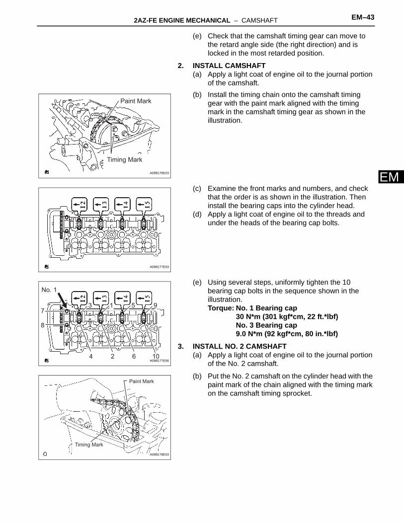
11. INSTALL CAMSHAFT(a) Apply a light coat of engine oil to the journal portion
of the camshaft.(b) Install the timing chain onto the camshaft timing
gear with the paint mark aligned with the timing mark on the camshaft timing gear as shown in the illustration.
(c) Examine the front marks and numbers, and check that the order is as shown in the illustration. Then install the bearing caps into the cylinder head.
(d) Apply a light coat of engine oil to the threads and under the heads of the bearing cap bolts.
08 5.080 (0.2000) 32 5.320 (0.2094) 56 5.560 (0.2189)
10 5.100 (0.2008) 34 5.340 (0.2102) 58 5.580 (0.2197)
12 5.120 (0.2016) 36 5.360 (0.2110) 60 5.600 (0.2205)
14 5.140 (0.2024) 38 5.380 (0.2118) 62 5.620 (0.2213)
16 5.160 (0.2031) 40 5.400 (0.2126) 64 5.640 (0.2220)
18 5.180 (0.2039) 42 5.420 (0.2134) 66 5.660 (0.2228)
20 5.200 (0.2047) 44 5.440 (0.2142) 68 5.680 (0.2236)
22 5.220 (0.2055) 46 5.460 (0.2150) 70 5.700 (0.2244)
24 5.240 (0.2063) 48 5.480 (0.2157) 72 5.720 (0.2252)
26 5.260 (0.2071) 50 5.500 (0.2165) 74 5.740 (0.2260)
28 5.280 (0.2079) 52 5.520 (0.2173) - -
Lifter No. Thicknessmm (in.)
Lifter No. Thicknessmm (in.)
Lifter No. Thicknessmm (in.)
Timing Mark
Paint Mark
A098176E04
A098177E03

2AZ-FE ENGINE MECHANICAL – VALVE CLEARANCE EM–15
M
E(e) Using several steps, uniformly tighten the 10 bearing cap bolts in the sequence shown in the illustration.Torque: No. 1 bearing cap
30 N*m (301 kgf*cm, 22 ft.*lbf)No. 3 bearing cap9.0 N*m (92 kgf*cm, 80 in.*lbf)
12. INSTALL NO. 2 CAMSHAFT(a) Apply a light coat of engine oil to the journal portion
of the No. 2 camshaft.
(b) Put the No. 2 camshaft on the cylinder head with the paint mark of the chain aligned with the timing mark on the camshaft timing sprocket.
(c) While holding the No. 2 camshaft by hand, temporarily tighten the camshaft timing sprocket set bolt.
(d) Examine the front marks and numbers, and check that the order is as shown in the illustration. Then install the bearing caps onto the cylinder head.
(e) Apply a light coat of engine oil to the threads and under the heads of the bearing cap bolts.
(f) Using several steps, uniformly tighten the 10 bearing cap bolts in the sequence shown in the illustration.Torque: No. 2 bearing cap
30 N*m (301 kgf*cm, 22 ft.*lbf)No. 3 bearing cap9.0 N*m (92 kgf*cm, 80 in.*lbf)
8
4 2 6 10
73 1 5 9
No. 1
A098177E06
Timing Mark
Paint Mark
A098178E03
A086659
A098174E05
7
3
4 2 6 10
1 5 9
8
No. 2A098174E07

EM–16 2AZ-FE ENGINE MECHANICAL – VALVE CLEARANCE
EM
(g) While holding the camshaft with a wrench, tighten the camshaft timing sprocket set bolt.Torque: 54 N*m (551 kgf*cm, 40 ft.*lbf)NOTICE:Be careful not to damage the valve lifter.
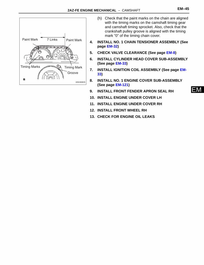
(h) Check that the paint marks on the chain are aligned with the timing marks on the camshaft timing gear and camshaft timing sprocket. Also, check that the crankshaft pulley groove is aligned with the timing mark "0" of the timing chain cover.
13. INSTALL NO. 1 CHAIN TENSIONER (See page EM-32)14. INSTALL CYLINDER HEAD COVER SUB-ASSEMBLY
(See page EM-33)15. INSTALL IGNITION COIL ASSEMBLY (See page EM-
33)16. CHECK FOR ENGINE OIL LEAKS17. INSTALL NO. 1 ENGINE COVER (See page EM-121)18. INSTALL FRONT FENDER APRON RH19. INSTALL ENGINE UNDER COVER LH20. INSTALL ENGINE UNDER COVER RH21. INSTALL FRONT WHEEL RH
Hold
Tighten
A098173E04
7 LinksPaint Mark Paint Mark
Timing Mark Timing Mark
Groove
A098180E04

2AZ-FE ENGINE MECHANICAL – TIMING CHAIN EM–17
M
EENGINE2AZ-FE ENGINE MECHANICALTIMING CHAINCOMPONENTS
FRONT FENDER APRON SEAL RH
N*m (kgf*cm, ft.*lbf) : Specified torque
ENGINE MOVING CONTROL ROD SUB-ASSEMBLY
NO. 1 ENGINE COVER SUB-ASSEMBLY
NO. 2 ENGINE MOUNTING BRACKET RH
NO. 2 ENGINE MOUNTING STAY RH
V-RIBBED BELT
64 (653, 47)
64 (653, 47)
52 (531, 38)
52 (531, 38)
21 (214, 15)
9.0 (92, 80 in.*lbf)
9.8 (100, 87 in.*lbf)
GENERATOR ASSEMBLY
A134948E01

EM–18 2AZ-FE ENGINE MECHANICAL – TIMING CHAIN
EM
ENGINE UNDER COVER RH
ENGINE UNDER COVER LH
N*m (kgf*cm, ft.*lbf) : Specified torque Non-reusable part
VANE PUMP ASSEMBLY
43 (439, 32)
FRONT EXHAUST
PIPE ASSEMBLY
EXHAUST PIPE GASKET
EXHAUST PIPE GASKET
FRONT EXHAUST PIPE NO. 1
SUPPORT BRACKET
62 (633, 46)
33 (337, 24) 33 (337, 24)
56 (571, 41)
REAR EXHAUST PIPE NO. 1
SUPPORT BRACKET
A134947E01

2AZ-FE ENGINE MECHANICAL – TIMING CHAIN EM–19
M
ECRANKSHAFT PULLEY
CYLINDER HEAD COVER SUB-ASSEMBLY
IGNITION COIL ASSEMBLY
N*m (kgf*cm, ft.*lbf) : Specified torque Non-reusable part
9.0 (92, 80 in.*lbf)
9.0 (92, 80 in.*lbf)
9.0 (92, 80 in.*lbf)
9.0 (92, 80 in.*lbf)
TMMK: 170 (1,733, 125) TMC: 180 (1,835, 133)
25 (255, 18)
11 (110, 8)
CYLINDER HEAD COVER GASKET
x12x2GASKETOIL PAN DRAIN PLUG
OIL PAN SUB-ASSEMBLY
CRANK POSITION SENSOR
11 (110, 8)
14 (143, 10)14 (143, 10)
x2x6
A134922E01

EM–20 2AZ-FE ENGINE MECHANICAL – TIMING CHAIN
EM
CHAIN SUB-ASSEMBLY
CHAIN TENSIONER SLIPPER
CRANKSHAFT TIMING SPROCKET
NO. 1 CHAIN TENSIONER ASSEMBLY
NO. 1 CHAIN VIBRATION DAMPER
NO. 1 CRANKSHAFT POSITION SENSOR PLATE
NO. 2 CHAIN SUB-ASSEMBLY
TIMING CHAIN CASE OIL SEAL
TIMING CHAIN COVER SUB-ASSEMBLY
TIMING CHAIN GUIDE
V-RIBBED BELT TENSIONER ASSEMBLY
OIL PUMP DRIVE SPROCKET
N*m (kgf*cm, ft.*lbf) : Specified torque
Non-reusable part
9.0 (92, 80 in.*lbf)
9.0 (92, 80 in.*lbf)
9.0 (92, 80 in.*lbf)
19 (194, 14)
60 (607, 44)
30 (301, 22)
12 (122, 9.0)
GASKET
OIL PUMP DRIVEN SPROCKET
CHAIN TENSIONER
SPRING
x4
x8
11 (112, 8)
55 (561, 41)
25 (255, 18)
22 (220, 16)STUD BOLT
A134923E01

2AZ-FE ENGINE MECHANICAL – TIMING CHAIN EM–21
M
EREMOVAL1. DISCONNECT CABLE FROM NEGATIVE BATTERY
TERMINAL2. REMOVE NO. 1 ENGINE COVER SUB-ASSEMBLY
(See page EM-94)3. REMOVE FRONT WHEEL RH4. REMOVE ENGINE UNDER COVER LH5. REMOVE ENGINE UNDER COVER RH6. REMOVE FRONT FENDER APRON SEAL RH7. DRAIN ENGINE OIL (See page LU-4)8. REMOVE FRONT EXHAUST PIPE ASSEMBLY
HINT:See page EX-2.
9. REMOVE NO. 2 ENGINE MOUNTING STAY RH (See page EM-95)
10. REMOVE ENGINE MOVING CONTROL ROD SUB-ASSEMBLY (See page EM-95)
11. REMOVE NO. 2 ENGINE MOUNTING BRACKET RH (See page EM-96)
12. REMOVE V-RIBBED BELT (See page EM-6)13. REMOVE GENERATOR ASSEMBLY (See page CH-11)14. REMOVE VANE PUMP ASSEMBLY (See page EM-
101)15. REMOVE IGNITION COIL ASSEMBLY (See page EM-
106)16. DISCONNECT VENTILATION HOSE17. DISCONNECT NO. 2 VENTILATION HOSE18. REMOVE CYLINDER HEAD COVER SUB-ASSEMBLY
(a) Remove the 2 bolts and disconnect the 2 engine wires.
A112210E01

EM–22 2AZ-FE ENGINE MECHANICAL – TIMING CHAIN
EM
(b) Remove the 8 bolts, 2 nuts, and the cylinder head cover.
19. SET NO. 1 CYLINDER TO TDC/COMPRESSION (See page EM-8)
20. REMOVE CRANKSHAFT PULLEY (See page EM-75)21. REMOVE CRANK POSITION SENSOR (See page ES-
411)
22. REMOVE OIL PAN SUB-ASSEMBLY(a) Remove the 12 bolts and 2 nuts.
(b) Insert the blade of SST between the crankcase and oil pan. Cut through the sealer and remove the oil pan.SST 09032-00100NOTICE:Be careful not to damage the contact surfaces of the crankcase, chain cover and oil pan.
23. REMOVE NO. 1 CHAIN TENSIONER ASSEMBLY(a) Remove the 2 nuts, tensioner and gasket.
NOTICE:Do not turn the crankshaft without the chain tensioner.
24. INSTALL ENGINE HANGERS(a) Install the No. 1 engine hanger and No. 2 engine
hanger with the bolts as shown in the illustration.Parts No.:
Torque: 38 N*m (387 kgf*cm, 28 ft.*lbf)(b) Attach the sling device to the engine hangers and
chain block.
A127550E02
A114333
SST
SST
A000019E05
A098348E01
No. 1 Engine Hanger No. 2 Engine Hanger
A052507E05
No. 1 Engine hanger 12281-28010
No. 2 Engine hanger 12282-28010
Bolt 91512-61020

2AZ-FE ENGINE MECHANICAL – TIMING CHAIN EM–23
M
E25. REMOVE V-RIBBED BELT TENSIONER ASSEMBLY(a) Lift the engine upward using the chain block.
NOTICE:Do not lift the engine more than necessary.
(b) Remove the bolt, nut and V-ribbed belt tensioner.
26. REMOVE ENGINE MOUNTING INSULATOR(a) Attach the engine chain hoist to the engine hangers.
CAUTION:Do not attempt to hang the engine by hooking the chain to any other part.
(b) Remove the bolt and disconnect the engine mounting insulator FR.
(c) M/T:Remove the bolt and disconnect the engine lateral control rod.
(d) Remove the 2 bolts and disconnect the steering gear return tube clamps from the frame.
A112212
A059880
M/T
A060825E02
A138332

EM–24 2AZ-FE ENGINE MECHANICAL – TIMING CHAIN
EM
(e) Remove the 4 nuts from the engine mounting insulator RH.
(f) Raise the engine and remove the engine mounting insulator RH.
27. REMOVE ENGINE MOUNTING BRACKET RH(a) Remove the 3 bolts and engine mounting bracket.
28. REMOVE TIMING CHAIN COVER SUB-ASSEMBLY (See page LU-11)
29. REMOVE TIMING CHAIN CASE OIL SEAL (See page LU-12)
30. REMOVE NO. 1 CRANKSHAFT POSITION SENSOR PLATE(a) Remove the crankshaft position sensor plate.
31. REMOVE CHAIN TENSIONER SLIPPER(a) Remove the bolt and chain tensioner slipper.
32. REMOVE NO. 1 CHAIN VIBRATION DAMPER(a) Remove the 2 bolts and chain vibration damper.
A059900
A052481
A132571
A125372
A125371
2AZ-FE ENGINE MECHANICAL – TIMING CHAIN EM–25
M
E33. REMOVE TIMING CHAIN GUIDE(a) Remove the bolt and timing chain guide.
34. REMOVE CHAIN SUB-ASSEMBLY(a) Remove the chain sub-assembly.
35. REMOVE CRANKSHAFT TIMING SPROCKET(a) Remove the crankshaft timing sprocket.
36. REMOVE NO. 2 CHAIN SUB-ASSEMBLY(a) Turn the crankshaft by 90° counterclockwise to align
the adjusting hole of the oil pump drive shaft sprocket with the groove of the oil pump.
A125373
A128185
A125374
Groove
90°
A098351E01

EM–26 2AZ-FE ENGINE MECHANICAL – TIMING CHAIN
EM
(b) Insert a 4 mm diameter bar into the adjusting hole of the oil pump drive shaft sprocket to lock the gear in position, and then remove the nut.
(c) Remove the bolt, chain tensioner plate and spring.
(d) Remove the chain tensioner, oil pump driven sprocket and chain.
GrooveA098352E01
Bolt
Spring
Chain Tensioner PlateB011415E03
A063847

2AZ-FE ENGINE MECHANICAL – TIMING CHAIN EM–27
M
EINSPECTION1. INSPECT CHAIN SUB-ASSEMBLY (See page EM-138)2. INSPECT NO. 2 CHAIN SUB-ASSEMBLY (See page
EM-138)3. INSPECT OIL PUMP DRIVE SPROCKET (See page
EM-138)4. INSPECT OIL PUMP DRIVE SHAFT SPROCKET (See
page EM-139)5. INSPECT CHAIN TENSIONER SLIPPER (See page
EM-140)6. INSPECT NO. 1 CHAIN VIBRATION DAMPER (See
page EM-140)7. INSPECT CHAIN TENSIONER PLATE (See page EM-
140)8. INSPECT NO. 1 CHAIN TENSIONER (See page EM-
140)INSTALLATION1. INSTALL NO. 2 CHAIN SUB-ASSEMBLY
(a) Set the crankshaft key into the left horizontal position.
(b) Turn the drive shaft so that the cutout faces upward.
(c) Align the yellow mark links with the timing marks of each gear as shown in the illustration.
(d) Install the sprockets onto the crankshaft and oil pump shaft with the chain wrapped on the gears.
(e) Temporarily tighten the oil pump drive shaft sprocket with the nut.
B011424
Timing Mark
Timing Mark
Mark Link
Mark Link
Oil Pump Drive Shaft Sprocket
Oil Pump Drive Sprocket
A094198E06

EM–28 2AZ-FE ENGINE MECHANICAL – TIMING CHAIN
EM
(f) Insert the damper spring into the adjusting hole, and then install the chain tensioner plate with the bolt.Torque: 12 N*m (122 kgf*cm, 9 ft.*lbf)
(g) Align the adjusting hole of the oil pump drive shaft sprocket with the groove of the oil pump.
(h) Insert a 4 mm diameter bar into the adjusting hole of the oil pump drive shaft gear to lock the gear in position, and then tighten the nut.Torque: 30 N*m (301 kgf*cm, 22 ft.*lbf)
(i) Rotate the crankshaft clockwise by 90°, and align the crankshaft key to the top.
2. INSTALL CRANKSHAFT TIMING SPROCKET(a) Install the crankshaft timing sprocket.
Spring
Bolt
Chain Tensioner PlateA090851E03
GrooveA052512E02
A036525
A125374

2AZ-FE ENGINE MECHANICAL – TIMING CHAIN EM–29
M
E3. INSTALL NO. 1 CHAIN VIBRATION DAMPER(a) Install the chain vibration damper with the 2 bolts.
Torque: 9.0 N*m (92 kgf*cm, 80 in.*lbf)
4. INSTALL CHAIN SUB-ASSEMBLY(a) Set the No. 1 cylinder to TDC/compression.
(1) Turn the camshafts with a wrench (using the hexagonal lobe) to align the timing marks of the camshaft timing gear with each timing mark located on the No. 1 and No. 2 bearing caps as shown in the illustration.
(2) Using the crankshaft pulley bolt, turn the crankshaft to position with the key on the crankshaft upward.
(b) Install the chain onto the crankshaft timing sprocket with the gold or pink mark link aligned with the timing mark on the crankshaft.
A132570
Timing Marks
Timing MarksA053018E05
A052505
Mark Link
Timing Mark
A094576E01
EM–30 2AZ-FE ENGINE MECHANICAL – TIMING CHAIN
EM
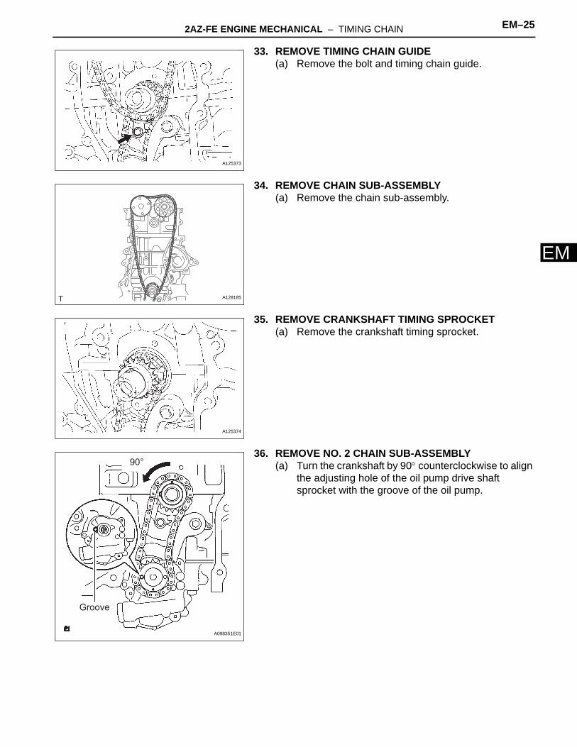
(c) Using SST and a hammer, tap in the crankshaft timing sprocket.SST 09309-37010
(d) Align the gold or yellow link with each timing mark located on the camshaft timing gear and sprocket, then install the chain.
5. INSTALL CHAIN TENSIONER SLIPPER(a) Install the chain tensioner slipper with the bolt.
Torque: 19 N*m (194 kgf*cm, 14 ft.*lbf)
6. INSTALL TIMING CHAIN GUIDE(a) Install the timing chain guide with the bolt.
Torque: 9.0 N*m (92 kgf*cm, 80 in.*lbf)
7. INSTALL NO. 1 CRANKSHAFT POSITION SENSOR PLATE(a) Install the sensor plate with the "F" mark facing
forward.
8. INSTALL TIMING CHAIN CASE OIL SEAL (See page LU-15)
9. INSTALL TIMING CHAIN COVER SUB-ASSEMBLY (See page LU-15)
SST
A098369E01
Timing MarkTiming Mark
Mark Link
A098370E01
Hold
A124787E01
A125373
A124770

2AZ-FE ENGINE MECHANICAL – TIMING CHAIN EM–31
M
E10. INSTALL V-RIBBED BELT TENSIONER ASSEMBLY(a) Install the V-ribbed belt tensioner with the bolt and
nut.Torque: 60 N*m (607 kgf*cm, 44 ft.*lbf)NOTICE:Do not lift the engine more than necessary.
11. INSTALL ENGINE MOUNTING BRACKET RH(a) Install the engine mounting bracket with the 3 bolts.
Torque: 54 N*m (551 kgf*cm, 40 ft.*lbf)
12. INSTALL ENGINE MOUNTING INSULATOR(a) Raise the engine and install the engine mounting
insulator RH.(b) Install the engine mounting insulator RH with the 4
nuts.Torque: Nut A
95 N*m (969 kgf*cm, 70 ft.*lbf)Nut B87 N*m (888 kgf*cm, 64 ft.*lbf)
(c) Install the steering gear return tube clamps to the frame with the 2 bolts.Torque: 8.0 N*m (80 kgf*cm, 69 in.*lbf)
(d) Install the engine mounting insulator FR with the bolt.Torque: 87 N*m (888 kgf*cm, 64 ft.*lbf)
A112212
A052481
A
BB
B
A059900E02
A138332
A059880

EM–32 2AZ-FE ENGINE MECHANICAL – TIMING CHAIN
EM
(e) M/T:Install the engine lateral control rod with the bolt.Torque: 89 N*m (910 kgf*cm, 66 ft.*lbf)
13. INSTALL OIL PAN SUB-ASSEMBLY(a) Remove any old packing material and be careful not
to drop any oil on the contact surfaces of the cylinder block and oil pan.
(b) Apply a continuous bead of seal packing (Diameter 3.0 to 4.0 mm (0.118 to 0.157 in.)) as shown in the illustration.Seal packing:
Toyota Genuine Seal Packing Block, Three Bond 1207B or Equivalent
NOTICE:• Remove any oil from the contact surfaces.• Install the oil pan within 3 minutes after
applying seal packing.• Do not start the engine for at least 2 hours
after installing.(c) Install the oil pan to the cylinder block.
(d) Uniformly tighten the 12 bolts and 2 nuts in the sequence shown in the illustration.Torque: 9.0 N*m (92 kgf*cm, 80 in.*lbf)
14. INSTALL CRANK POSITION SENSOR (See page ES-411)
15. INSTALL CRANKSHAFT PULLEY (See page EM-76)
16. INSTALL NO. 1 CHAIN TENSIONER ASSEMBLY(a) Release the ratchet pawl, then fully push in the
plunger and hook the hook to the pin so that the plunger is in the position shown in the illustration.
M/T
A060825E01
Seal Packing
6.0 mm (0.236 in.)
Seal Diameter: 3.0 to 4.0 mmA114332E01
1, 1510
1112
13
14
9
8
7
6
54 3 2 A114333E01
Push
Raise
PinHook
A098376E03

2AZ-FE ENGINE MECHANICAL – TIMING CHAIN EM–33
M
E(b) Install a new gasket and the chain tensioner with the 2 nuts.Torque: 9.0 N*m (92 kgf*cm, 80 in.*lbf)NOTICE:If the hook releases the plunger while the chain tensioner is being installed, set the hook again.
(c) Turn the crankshaft counterclockwise, then disconnect the plunger knock pin from the hook.
(d) Turn the crankshaft clockwise, then check that the plunger is extended.
17. INSTALL CYLINDER HEAD COVER SUB-ASSEMBLY(a) Remove any old packing material from the contact
surface.
Engine Front
A098377E03
Turn
Disconnect
Pin
Hook
A112204E02
TurnPush
Plunger
A112205E02

EM–34 2AZ-FE ENGINE MECHANICAL – TIMING CHAIN
EM
(b) Apply seal packing to the 2 locations shown in the illustration.Seal packing:
Toyota Genuine Seal Packing Block, Three Bond 1207B or Equivalent
NOTICE:• Remove any oil from the contact surface.• Install the cylinder head cover within 3
minutes of applying seal packing.• Do not add engine oil for at least 2 hours after
installing the cylinder head cover.(c) Install the cylinder head cover with the 8 bolts and 2
nuts.Torque: Bolt A
11 N*m (112 kgf*cm, 8 ft.*lbf)Bolt B14 N*m (143 kgf*cm, 10 ft.*lbf)Nut11 N*m (112 kgf*cm, 8 ft.*lbf)
(d) Install the 2 engine wires with the 2 bolts.Torque: 8.4 N*m (86 kgf*cm, 74 in.*lbf)
18. INSTALL NO. 2 VENTILATION HOSE19. INSTALL VENTILATION HOSE20. INSTALL IGNITION COIL ASSEMBLY
(a) Install the 4 ignition coils with the 4 bolts.Torque: 9.0 N*m (92 kgf*cm, 80 in.*lbf)
21. INSTALL VANE PUMP ASSEMBLY (See page EM-113)22. INSTALL GENERATOR ASSEMBLY (See page CH-19)23. INSTALL V-RIBBED BELT (See page EM-6)24. INSTALL NO. 2 ENGINE MOUNTING BRACKET RH
(See page EM-118)25. INSTALL ENGINE MOVING CONTROL ROD SUB-
ASSEMBLY (See page EM-119)26. INSTALL NO. 2 ENGINE MOUNTING STAY RH (See
page EM-119)27. INSTALL FRONT EXHAUST PIPE ASSEMBLY
HINT:See page EX-3.
28. ADD ENGINE OIL29. CONNECT CABLE TO NEGATIVE BATTERY
TERMINAL (See page EM-120)30. CHECK FOR ENGINE OIL LEAKS31. CHECK FOR EXHAUST GAS LEAKS32. CHECK IGNITION TIMING (See page EM-1)
A094205E01
NutNut
A A AA
AA
BB
A127550E01
A112210

2AZ-FE ENGINE MECHANICAL – TIMING CHAIN EM–35
M
E33. INSTALL FRONT FENDER APRON SEAL RH34. INSTALL ENGINE UNDER COVER LH35. INSTALL ENGINE UNDER COVER RH36. INSTALL FRONT WHEEL RH37. INSTALL NO. 1 ENGINE COVER SUB-ASSEMBLY
(See page EM-121)

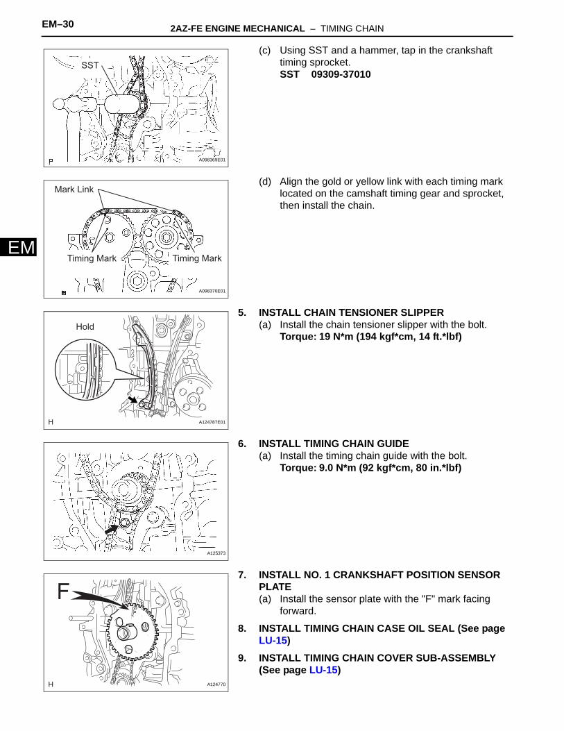
2AZ-FE ENGINE MECHANICAL – CAMSHAFT EM–35
M
EENGINE2AZ-FE ENGINE MECHANICALCAMSHAFTCOMPONENTS
NO. 1 ENGINE COVER SUB-ASSEMBLY
V-RIBBED BELT9.0 (92, 80 in.*lbf)
FRONT FENDER APRON SEAL RH
ENGINE UNDER COVER RH
ENGINE UNDER COVER LH
N*m (kgf*cm, ft.*lbf) : Specified torqueA134949E01
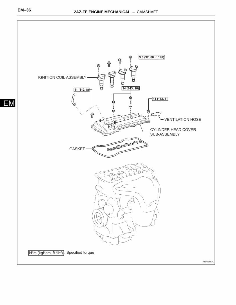
EM–36 2AZ-FE ENGINE MECHANICAL – CAMSHAFT
EM
N*m (kgf*cm, ft.*lbf) : Specified torque
9.0 (92, 80 in.*lbf)
11 (112, 8)
11 (112, 8) 14 (143, 10)
CYLINDER HEAD COVER SUB-ASSEMBLY
IGNITION COIL ASSEMBLY
GASKET
VENTILATION HOSE
A134919E01

2AZ-FE ENGINE MECHANICAL – CAMSHAFT EM–37
M
EN*m (kgf*cm, ft.*lbf) : Specified torque
Non-reusable part
9.0 (92, 80 in.*lbf)
9.0 (92, 80 in.*lbf)
54 (551, 40)
54 (551, 40)
30 (301, 22)
GASKET
NO. 1 CHAIN TENSIONER ASSEMBLY
CAMSHAFT
CAMSHAFT TIMING GEAR ASSEMBLY
x16
x4
NO. 3 CAMSHAFT BEARING CAP
NO. 3 CAMSHAFT BEARING CAP
NO. 2 CAMSHAFT BEARING CAP
NO. 2 CAMSHAFT TIMING SPROCKET
NO. 1 CAMSHAFT BEARING CAP
NO. 2 CAMSHAFT
A134921E01

EM–38 2AZ-FE ENGINE MECHANICAL – CAMSHAFT
EM
REMOVAL1. REMOVE FRONT WHEEL RH2. REMOVE ENGINE UNDER COVER LH3. REMOVE ENGINE UNDER COVER RH4. REMOVE FRONT FENDER APRON SEAL RH5. REMOVE NO. 1 ENGINE COVER SUB-ASSEMBLY
(See page EM-94)6. REMOVE IGNITION COIL ASSEMBLY (See page EM-
106)7. REMOVE CYLINDER HEAD COVER SUB-ASSEMBLY
(See page EM-21)8. SET NO. 1 CYLINDER TO TDC/COMPRESSION (See
page EM-8)9. REMOVE NO. 1 CHAIN TENSIONER ASSEMBLY (See
page EM-22)10. REMOVE NO. 2 CAMSHAFT
(a) While holding the camshaft with a wrench, loosen the camshaft timing set bolt.
(b) Using several steps, uniformly loosen and remove the 10 bearing cap bolts in the sequence shown in the illustration.
(c) Remove the 5 bearing caps.
(d) While holding the No. 2 camshaft by hand, remove the camshaft timing sprocket set bolt.
(e) Remove the camshaft timing sprocket from the No. 2 camshaft with the timing chain wrapped on the sprocket.
(f) Remove the camshaft timing sprocket from the timing chain.
Loosen
Hold
A098173E03
1
5
6 810 4
79 3
2
A098174E11
A086659

2AZ-FE ENGINE MECHANICAL – CAMSHAFT EM–39
M
E11. REMOVE CAMSHAFT(a) Using several steps, uniformly loosen and remove
the 10 bearing cap bolts in the sequence shown in the illustration.
(b) Remove the 5 bearing caps.(c) Remove the camshaft and camshaft timing gear
while holding the timing chain by hand.
(d) Tie the timing chain with a string as shown in the illustration.NOTICE:Be careful not to drop anything inside the timing chain cover.
12. REMOVE CAMSHAFT TIMING GEAR ASSEMBLY(a) Clamp the camshaft in a vise, and make sure that
the camshaft timing gear does not rotate.(b) Cover all the oil ports except the advance side port
shown in the illustration with vinyl tape.
(c) Apply air pressure of 100 kPa (1.0 kgf/cm2, 14 psi) to the oil path, then turn the camshaft timing gear in the advance direction (counterclockwise) by hand.CAUTION:Cover the paths with a shop rag or piece of cloth to avoid oil splashes.HINT:Depending on the air pressure, the camshaft timing gear will turn to the advance angle side without applying force by hand. Also, if the pressure is difficult to apply because of air leakage from the port, the lock may be difficult to release.
1
2
6
5 79 3
810 4A098175E04
A052474
Advance Side Port
A090848E03
A031032

EM–40 2AZ-FE ENGINE MECHANICAL – CAMSHAFT
EM
(d) Remove the flange bolt of the camshaft timing gear.NOTICE:• Be sure not to remove the other 4 bolts.• If planning to reuse the gear, be sure to
release the straight pin lock before installing the gear.
INSPECTION1. INSPECT CAMSHAFT TIMING GEAR ASSEMBLY
(a) Check the lock of the camshaft timing gear.(1) Clamp the camshaft in a vise, and confirm that
the camshaft timing gear is locked.NOTICE:Be careful not to damage the camshaft.
(b) Release the lock pin.(1) Cover the 4 oil paths of the cam journal with
vinyl tape as shown in the illustration.HINT:The 2 advance side paths are provided in the groove of the camshaft. Plug one of the paths with a rubber piece.
(2) Break through the tape of the advance side path and the retard side path on the opposite side to the hole of the advance side path, as shown in the illustration.
(3) Apply approximately 200 kPa (2.0 kgf/cm2, 28 psi) of air pressure to the two broken paths.CAUTION:Cover the paths with a piece of cloth when applying pressure to keep oil from splashing.
(4) Check that the camshaft timing gear revolves in the advance direction when reducing the air pressure of the retard side path.OK:
Gear rotates in the advance direction.HINT:This operation releases the lock pin for the most retarded position.
A032639
Retard Side
Path
Advance
Side Path
Open
CloseOpen
Close
RubberVinyl Tape
A062190E02
Retard
Side Path
Advance
Side Path
A062191E03

2AZ-FE ENGINE MECHANICAL – CAMSHAFT EM–41
M
E(5) When the camshaft timing gear reaches the most advanced position, remove the air gun from the retard side path and advance side path, in that order.NOTICE:Do not remove the air gun from the advance side path first. The gear may abruptly shift in the retard direction and break the lock pin.
(c) Check for smooth rotation.(1) Rotate the camshaft timing gear within its
movable range several times, but do not turn it to the most retarded position. Check that the gear rotates smoothly.OK:
Gear rotates smoothly.NOTICE:Do not use an air gun to check for smooth operation.
(d) Check the lock in the most retarded position.(1) Confirm that the camshaft timing gear is locked
at the most retarded position.2. INSPECT CAMSHAFT
(a) Inspect the camshaft for runout.(1) Place the camshaft on V-blocks.(2) Using a dial indicator, measure the circle runout
at the center journal.Maximum circle runout:
0.03 mm (0.0012 in.)If the circle runout is greater than the maximum, replace the camshaft.
(b) Inspect the cam lobes.(1) Using a micrometer, measure the cam lobe
height.Standard cam lobe height:
47.306 to 47.406 mm (1.8624 to 1.8664 in.)Minimum cam lobe height:
47.196 mm (1.8581 in.)If the cam lobe height is less than the minimum, replace the camshaft.
(c) Inspect the camshaft journals.(1) Using a micrometer, measure the journal
diameter.Standard journal diameter
EM01628E01
A036687E01
A036688E01
Journal Position Specified Condition
No. 1 35.971 to 35.985 mm (1.4162 to 1.4167 in.)
Other 22.959 to 22.975 mm (0.9039 to 0.9045 in.)

EM–42 2AZ-FE ENGINE MECHANICAL – CAMSHAFT
EM
If the journal diameter is not as specified, check the oil clearance.
3. INSPECT NO. 2 CAMSHAFT(a) Inspect the camshaft for runout.
(1) Place the camshaft on V-blocks.(2) Using a dial indicator, measure the circle runout
at the center journal.Maximum circle runout:
0.03 mm (0.0012 in.)If the circle runout is greater than the maximum, replace the No. 2 camshaft.
(b) Inspect the cam lobes.(1) Using a micrometer, measure the cam lobe
height.Standard cam lobe height:
45.983 to 46.083 mm (1.8104 to 1.8143 in.)Minimum cam lobe height:
45.873 mm (1.8060 in.)If the cam lobe height is less than the minimum, replace the No. 2 camshaft.
(c) Inspect the camshaft journals.(1) Using a micrometer, measure the journal
diameter.Standard journal diameter
If the journal diameter is not as specified, check the oil clearance.
INSTALLATION1. INSTALL CAMSHAFT TIMING GEAR ASSEMBLY
(a) Put the camshaft timing gear and camshaft together with the straight pin and key groove misaligned, as shown in the illustration.
(b) Turn the camshaft timing gear as shown in the illustration while pushing it gently against the camshaft. Push further at the position where the pin fits into the groove.NOTICE:Be sure not to turn the camshaft timing gear to the retard angle side (the right angle).
(c) Check that there is no clearance between the gear and camshaft.
(d) Tighten the flange bolt with the camshaft timing gear fixed in place.Torque: 54 N*m (551 kgf*cm, 40 ft.*lbf)
EM01628E01
A036687E01
A036688E01
Journal Position Specified Condition
No. 1 35.971 to 35.985 mm (1.4162 to 1.4167 in.)
Other 22.959 to 22.975 mm (0.9039 to 0.9045 in.)
Straight Pin
Key GrooveA098365E02
2AZ-FE ENGINE MECHANICAL – CAMSHAFT EM–43
M
E(e) Check that the camshaft timing gear can move to the retard angle side (the right direction) and is locked in the most retarded position.
2. INSTALL CAMSHAFT(a) Apply a light coat of engine oil to the journal portion
of the camshaft.(b) Install the timing chain onto the camshaft timing
gear with the paint mark aligned with the timing mark in the camshaft timing gear as shown in the illustration.
(c) Examine the front marks and numbers, and check that the order is as shown in the illustration. Then install the bearing caps into the cylinder head.
(d) Apply a light coat of engine oil to the threads and under the heads of the bearing cap bolts.
(e) Using several steps, uniformly tighten the 10 bearing cap bolts in the sequence shown in the illustration.Torque: No. 1 Bearing cap
30 N*m (301 kgf*cm, 22 ft.*lbf)No. 3 Bearing cap9.0 N*m (92 kgf*cm, 80 in.*lbf)
3. INSTALL NO. 2 CAMSHAFT(a) Apply a light coat of engine oil to the journal portion
of the No. 2 camshaft.
(b) Put the No. 2 camshaft on the cylinder head with the paint mark of the chain aligned with the timing mark on the camshaft timing sprocket.
Timing Mark
Paint Mark
A098176E03
A098177E03
8
4 2 6 10
73 1 5 9
No. 1
A098177E06
Timing Mark
Paint Mark
A098178E03

EM–44 2AZ-FE ENGINE MECHANICAL – CAMSHAFT
EM
(c) While holding the No. 2 camshaft by hand, temporarily tighten the camshaft timing sprocket set bolt.
(d) Examine the front marks and numbers, and check that the order is as shown in the illustration. Then install the bearing caps onto the cylinder head.
(e) Apply a light coat of engine oil to the threads and under the heads of the bearing cap bolts.
(f) Using several steps, uniformly tighten the 10 bearing cap bolts in the sequence shown in the illustration.Torque: No. 2 Bearing cap
30 N*m (301 kgf*cm, 22 ft.*lbf)No. 3 Bearing cap9.0 N*m (92 kgf*cm, 80 in.*lbf)
(g) While holding the camshaft with a wrench, tighten the camshaft timing sprocket set bolt.Torque: 54 N*m (551 kgf*cm, 40 ft.*lbf)
A086659
A098174E05
7
3
4 2 6 10
1 5 9
8
No. 2A098174E07
Hold
Tighten
A098173E04
2AZ-FE ENGINE MECHANICAL – CAMSHAFT EM–45
M
E(h) Check that the paint marks on the chain are aligned with the timing marks on the camshaft timing gear and camshaft timing sprocket. Also, check that the crankshaft pulley groove is aligned with the timing mark "0" of the timing chain cover.
4. INSTALL NO. 1 CHAIN TENSIONER ASSEMBLY (See page EM-32)
5. CHECK VALVE CLEARANCE (See page EM-8)6. INSTALL CYLINDER HEAD COVER SUB-ASSEMBLY
(See page EM-33)7. INSTALL IGNITION COIL ASSEMBLY (See page EM-
33)8. INSTALL NO. 1 ENGINE COVER SUB-ASSEMBLY
(See page EM-121)9. INSTALL FRONT FENDER APRON SEAL RH10. INSTALL ENGINE UNDER COVER LH11. INSTALL ENGINE UNDER COVER RH12. INSTALL FRONT WHEEL RH13. CHECK FOR ENGINE OIL LEAKS
7 Links Paint MarkPaint Mark
Timing Marks Timing MarkGroove
A052460E05

EM–46 2AZ-FE ENGINE MECHANICAL – CYLINDER HEAD
EM
ENGINE2AZ-FE ENGINE MECHANICALCYLINDER HEADCOMPONENTS
COWL TOP PANEL OUTER SUB-ASSEMBLY
FRONT WIPER ARM AND BLADE ASSEMBLY RH
FRONT WIPER ARM AND BLADE ASSEMBLY LH
FRONT FENDER TO COWL SIDE SEAL RH
COWL TOP VENTILATOR LOUVER SUB-ASSEMBLY
FRONT FENDER TO COWL SIDE SEAL LH
N*m (kgf*cm, ft.*lbf) : Specified torque
5.0 (51, 44 in.*lbf)
7.5 (77, 66 in.*lbf)85 (867, 63)
20 (204, 15)
WINDSHIELD WIPER LINK ASSEMBLY
A136912E01

2AZ-FE ENGINE MECHANICAL – CYLINDER HEAD EM–47
M
EFRONT FENDER APRON SEAL RH
N*m (kgf*cm, ft.*lbf) : Specified torque
ENGINE MOVING CONTROL ROD SUB-ASSEMBLY
NO. 1 ENGINE COVER SUB-ASSEMBLY
NO. 2 ENGINE MOUNTING BRACKET RH
NO. 2 ENGINE MOUNTING STAY RH
V-RIBBED BELT
64 (653, 47)
64 (653, 47)
52 (531, 38)
52 (531, 38)
21 (214, 15)
9.0 (92, 80 in.*lbf)
9.8 (100, 87 in.*lbf)
GENERATOR ASSEMBLY
A134948E01
EM–48 2AZ-FE ENGINE MECHANICAL – CYLINDER HEAD
EM
AIR CLEANER CAP SUB-ASSEMBLY
AIR CLEANER CASE SUB-ASSEMBLY
AIR CLEANER INLET ASSEMBLYBATTERY
N*m (kgf*cm, ft.*lbf) : Specified torque
BATTERY TRAY
9.0 (92, 80 in.*lbf)
5.0 (51, 44 in.*lbf)5.0 (51, 44 in.*lbf)
3.5 (36, 31 in.*lbf)
A134950E01

2AZ-FE ENGINE MECHANICAL – CYLINDER HEAD EM–49
M
EENGINE UNDER COVER RH
ENGINE UNDER COVER LH
N*m (kgf*cm, ft.*lbf) : Specified torque Non-reusable part
VANE PUMP ASSEMBLY
43 (439, 32)
FRONT EXHAUST
PIPE ASSEMBLY
EXHAUST PIPE GASKET
EXHAUST PIPE GASKET
FRONT EXHAUST PIPE NO. 1
SUPPORT BRACKET
62 (633, 46)
33 (337, 24) 33 (337, 24)
56 (571, 41)
REAR EXHAUST PIPE NO. 1
SUPPORT BRACKET
A134947E01

EM–50 2AZ-FE ENGINE MECHANICAL – CYLINDER HEAD
EM
FUEL DELIVERY PIPE WITH INJECTOR
SPACER
N*m (kgf*cm, ft.*lbf) : Specified torque Non-reusable part
20 (204, 15)
30 (306, 22)
12 (122, 9)
44 (449, 32)
44 (449, 32)
44 (449, 32)
37 (378, 27)
INTAKE MANIFOLD
MANIFOLD STAY
NO. 2 MANIFOLD STAY
NO. 1 INTAKE MANIFOLD INSULATOR
GASKET
GASKET
VENTILATION HOSE
VENTILATION HOSE NO. 2
For PZEV:
EXHAUST MANIFOLD CONVERTER SUB-ASSEMBLY
x5
INSURATOR
NO. 1 MANIFOLD CONVERTER INSULATOR
INTAKE AIR CONTROL VALVE (For PZEV)
A136908E02

2AZ-FE ENGINE MECHANICAL – CYLINDER HEAD EM–51
M
ECAMSHAFT
CYLINDER HEAD GASKET
CYLINDER HEAD SUB-ASSEMBLY
NO. 2 CAMSHAFT
NO. 2 CAMSHAFT BEARING
N*m (kgf*cm, ft.*lbf) : Specified torque
Non-reusable part
9.0 (92, 80 in.*lbf)
1st: 70 (714, 52) 2nd: Turn 90 °
9.0 (92, 80 in.*lbf)
30 (301, 22)
54 (551, 39)
NO. 3 BEARING CAP
NO. 2 BEARING CAP
NO. 1 BEARING CAP
x16
x10
x4
CAMSHAFT BEARING NO. 1
CAMSHAFT TIMING GEAR ASSEMBLY
CAMSHAFT TIMING SPROCKET
OIL CONTROL VALVE
O-RING
CYLINDER HEAD BOLT
A134951E01

EM–52 2AZ-FE ENGINE MECHANICAL – CYLINDER HEAD
EM
VALVE SPRING RETAINER LOCK
VALVE SPRING RETAINERVALVE SPRING RETAINER
VALVE SPRING RETAINER LOCK
INNER COMPRESSION SPRINGINNER COMPRESSION SPRING
5.0 (51, 44 in.*lbf)
9.5 (97, 84 in.*lbf)
9.5 (97, 84 in.*lbf)
5.0 (51, 44 in.*lbf)
N*m (kgf*cm, ft.*lbf) : Specified torque Non-reusable part
EXHAUST VALVE INTAKE VALVE
STUD BOLT
STUD BOLT
STUD BOLT
STUD BOLT
VALVE LIFTERVALVE LIFTER
VALVE SPRING SEATVALVE SPRING SEAT
EXHAUST VALVE GUIDE BUSHINTAKE VALVE GUIDE BUSH
RING PIN
NO. 1 STRAIGHT SCREW PLUG
5.0 (51, 44 in.*lbf)
STUD BOLT
GASKET
GASKET
NO. 1 STRAIGHT SCREW PLUG
86 (879, 64)
86 (879, 64)
VALVE STEM OIL SEALVALVE STEM OIL SEAL
A136083E01

2AZ-FE ENGINE MECHANICAL – CYLINDER HEAD EM–53
M
EREMOVAL1. DISCHARGE FUEL SYSTEM PRESSURE
HINT:See page FU-1.
2. DISCONNECT CABLE FROM NEGATIVE BATTERY TERMINAL
3. REMOVE ENGINE UNDER COVER LH4. REMOVE ENGINE UNDER COVER RH5. REMOVE FRONT FENDER APRON SEAL RH6. REMOVE NO. 1 ENGINE COVER SUB-ASSEMBLY
(See page EM-94)7. DRAIN ENGINE COOLANT (See page CO-5)8. DRAIN ENGINE OIL (See page LU-4)9. REMOVE WINDSHIELD WIPER LINK ASSEMBLY
HINT:See page WW-9.
10. REMOVE COWL TOP PANEL OUTER SUB-ASSEMBLY (See page ES-424)
11. REMOVE AIR CLEANER INLET ASSEMBLY (See page EM-94)
12. REMOVE AIR CLEANER CAP SUB-ASSEMBLY (See page ES-416)
13. REMOVE AIR CLEANER CASE SUB-ASSEMBLY (See page EM-95)
14. REMOVE BATTERY (See page EM-95)15. REMOVE THROTTLE BODY ASSEMBLY (See page
ES-417)16. DISCONNECT FUEL TUBE SUB-ASSEMBLY (See
page FU-12)17. REMOVE FUEL DELIVERY PIPE WITH INJECTOR
(See page FU-13)18. REMOVE INTAKE MANIFOLD (See page ES-424)19. REMOVE INTAKE AIR CONTROL VALVE (For PZEV)
(See page IT-7)20. REMOVE NO. 1 INTAKE MANIFOLD INSULATOR (See
page EM-103)21. REMOVE FRONT EXHAUST PIPE ASSEMBLY
HINT:See page EX-2.
22. REMOVE NO. 2 ENGINE MOUNTING STAY RH (See page EM-95)
23. REMOVE ENGINE MOVING CONTROL ROD SUB-ASSEMBLY (See page EM-95)

EM–54 2AZ-FE ENGINE MECHANICAL – CYLINDER HEAD
EM
24. REMOVE NO. 2 ENGINE MOUNTING BRACKET RH (See page EM-96)
25. REMOVE V-RIBBED BELT (See page EM-6)26. REMOVE GENERATOR ASSEMBLY (See page CH-11)27. REMOVE OIL LEVEL GAUGE SUB-ASSEMBLY28. REMOVE OIL LEVEL GAUGE GUIDE (See page EM-
104)29. REMOVE MANIFOLD STAY (See page EM-104)30. REMOVE NO. 2 MANIFOLD STAY (See page EM-104)31. REMOVE EXHAUST MANIFOLD CONVERTER SUB-
ASSEMBLY (See page EM-104)32. REMOVE CHAIN SUB-ASSEMBLY
HINT:See page EM-21.
33. REMOVE NO. 2 CAMSHAFT(a) Using several steps, uniformly loosen and remove
the 10 bearing cap bolts in the sequence shown in the illustration.
(b) Remove the 5 bearing caps and No. 2 camshaft.
34. REMOVE CAMSHAFT(a) Using several steps, uniformly loosen and remove
the 10 bearing cap bolts in the sequence shown in the illustration.
(b) Remove the 5 bearing caps and camshaft.
35. REMOVE CAMSHAFT TIMING OIL CONTROL VALVE ASSEMBLY (See page ES-405)
36. DISCONNECT RADIATOR HOSE INLET (See page EM-96)
37. DISCONNECT ENGINE WIRE(a) Disconnect the radio setting condenser connector.(b) Disconnect the engine oil pressure switch
connector.(c) Disconnect the engine coolant temperature sensor
connector.(d) Disconnect the camshaft position sensor connector.(e) Remove the bolt and ground cable.
1
5
6 810 4
79 3
2
A098174E11
1
2
6
5 79 3
810 4A098175E04
A098748E01

2AZ-FE ENGINE MECHANICAL – CYLINDER HEAD EM–55
M
E38. REMOVE NO. 2 CAMSHAFT BEARING(a) Remove the No. 2 camshaft bearing.
39. REMOVE CYLINDER HEAD SUB-ASSEMBLY(a) Using several steps, uniformly loosen and remove
the 10 cylinder head bolts and 10 plate washers with a 10 mm bi-hexagon wrench in the sequence shown in the illustration.NOTICE:Head warpage or cracking could result from removing the bolts in the wrong order.
(b) Using a screwdriver with its tip wrapped with tape, pry between the cylinder head and cylinder block, and remove the cylinder head.NOTICE:Be careful not to damage the contact surfaces of the cylinder head and cylinder block.
40. REMOVE CYLINDER HEAD GASKET(a) Remove the cylinder head gasket.
DISASSEMBLY1. REMOVE VALVE LIFTER
(a) Remove the valve lifters.HINT:Arrange the valve lifters in the correct order.
A128879
1 5 9 7 3
461082F050595E01
A126930
A126929
A062842E01

EM–56 2AZ-FE ENGINE MECHANICAL – CYLINDER HEAD
EM
2. REMOVE INTAKE VALVE(a) Using SST and wooden blocks, compress and
remove the valve retainer locks.SST 09202-70020 (09202-00010)
(b) Remove the retainer, valve spring and valve.HINT:Arrange the removed parts in the correct order.
3. REMOVE EXHAUST VALVE(a) Using SST and wooden blocks, compress and
remove the valve retainer locks.SST 09202-70020 (09202-00010)
(b) Remove the retainer, valve spring and valve.HINT:Arrange the removed parts in the correct order.
4. REMOVE VALVE STEM OIL SEAL(a) Using needle-nose pliers, remove the oil seals.
5. REMOVE VALVE SPRING SEAT(a) Using compressed air and a magnetic finger,
remove the valve spring seats by blowing air onto them.
6. REMOVE NO. 1 STRAIGHT SCREW PLUG(a) Using a 14 mm straight hexagon wrench, remove
the 2 screw plugs and 2 gaskets.NOTICE:If water leaks from the straight screw plug or the plug corrodes, replace it.
7. REMOVE STUD BOLT8. REMOVE RING PIN
Wooden Block
SST
A128225E01
SST
Wooden BlockA128226E01
A013356E04
A062845E01
A062841

2AZ-FE ENGINE MECHANICAL – CYLINDER HEAD EM–57
M
E9. REMOVE INTAKE VALVE GUIDE BUSH(a) Heat the cylinder head to 80 to 100°C (176 to
212°F). (b) Place the cylinder head on wooden blocks.(c) Using SST and a hammer, tap out the guide bush.
SST 09201-10000 (09201-01050), 09950-70010 (09951-07100)
10. REMOVE EXHAUST VALVE GUIDE BUSH(a) Heat the cylinder head to 80 to 100°C (176 to
212°F). (b) Place the cylinder head on wooden blocks.
(c) Using SST and a hammer, tap out the guide bush.SST 09201-10000 (09201-01050), 09950-70010
(09951-07100)
INSPECTION1. INSPECT CYLINDER HEAD FOR FLATNESS
(a) Using a precision straight edge and a feeler gauge, measure the surface contacting the cylinder block and the manifolds for warpage.Maximum warpage
If the warpage is greater than the maximum, replace the cylinder head.
SST
A036632E01
SST
A036633E03
Cylinder Block Side:
Intake Manifold Side:
Exhaust Manifold Side:
A052445E01
Item Specified Condition
Cylinder block side 0.05 mm (0.0020 in.)
Intake manifold side 0.08 mm (0.0031 in.)
Exhaust manifold side 0.08 mm (0.0031 in.)

EM–58 2AZ-FE ENGINE MECHANICAL – CYLINDER HEAD
EM
2. INSPECT CYLINDER HEAD FOR CRACKS(a) Using a dye penetrant, check the intake ports,
exhaust ports and cylinder surface for cracks.If cracked, replace the cylinder head.
3. INSPECT VALVE SEATS(a) Apply a light coat of prussian blue to the valve face.(b) Lightly press the valve face against the valve seat.(c) Check the valve face and valve seat according to
the following procedure:(1) If prussian blue appears 360° around the valve
face, the valve face is concentric. If not, replace the valve.
(2) If prussian blue appears 360° around the valve seat, the guide and valve face are concentric. If not, resurface the valve seat.
(3) Check that the valve seat contact is in the middle of the valve face with the width between 1.0 to 1.4 mm (Intake side (0.039 to 0.055 in.)).
(4) Check that the valve seat contact is in the middle of the valve face with the width between 1.2 to 1.6 mm (Exhaust side (0.047 to 0.063 in.)).
4. REPAIR VALVE SEATSNOTICE:• Repair the seat while checking the seating
position.• Keep the lip free from foreign matter.(a) Using a 45° cutter, resurface the valve seat so that
the valve seat width is more than the specification.
A013365
Width
A052446E01
A128228

2AZ-FE ENGINE MECHANICAL – CYLINDER HEAD EM–59
M
E(b) Using 30° and 75° cutters, correct the valve seat so that the valve contacts the entire circumference of the seat. The contact should be in the center of the valve seat, and the valve seat width should be maintained within the specified range around the entire circumference of the seat.Valve Seat Width
(c) Handrub the valve and valve seat with an abrasive compound.
(d) Check the valve seating position.
5. INSPECT CAMSHAFT THRUST CLEARANCE(a) Install the camshafts (See page EM-70).(b) Using a dial indicator, measure the thrust clearance
while moving the camshaft back and forth.Standard thrust clearance
Maximum thrust clearance
If the thrust clearance is greater than the maximum, replace the cylinder head. If the thrust surface is damaged, replace the camshaft.
6. INSPECT CAMSHAFT OIL CLEARANCE(a) Clean the bearing caps and camshaft journals.(b) Place the camshafts on the cylinder head.(c) Lay a strip of Plastigage across each of the
camshaft journals.(d) Install the bearing caps (See page EM-70).
NOTICE:Do not turn the camshaft.
(e) Remove the bearing caps (See page EM-53).
75° 45°30°
Width
A128227E01
Item Specified Condition
Intake Side 1.0 to 1.4 mm (0.039 to 0.055 in.)
Exhaust Side 1.2 to 1.6 mm (0.047 to 0.063 in.)
A036626
Item Specified Condition
Intake 0.040 to 0.095 mm (0.0016 to 0.0037 in.)
Exhaust 0.080 to 0.135 mm (0.0032 to 0.0053 in.)
Item Specified Condition
Intake 0.110 mm (0.0043 in.)
Exhaust 0.150 mm (0.0059 in.)
Plastigage
A036627E03

EM–60 2AZ-FE ENGINE MECHANICAL – CYLINDER HEAD
EM
(f) Measure the Plastigage at its widest point.Standard oil clearance
Maximum oil clearance
NOTICE:Completely remove the Plastigage after the inspection.• If the oil clearance is greater than the maximum,
replace the camshaft. If necessary, replace the cylinder head.
• If the oil clearance on the camshaft No. 1 journal is greater than the maximum, choose a new bearing and install it.
(1) Check the number mark shown in the illustration.Cylinder head journal bore diameter
Standard bearing center wall thickness
Camshaft journal diameter
Plastigage
A036628E01
Item Specified Condition
Camshaft No. 1 journal bearing mark 1 0.007 to 0.038 mm (0.0003 to 0.0015 in.)
Camshaft No. 1 journal bearing mark 2 0.008 to 0.038 mm (0.0003 to 0.0015 in.)
Camshaft No. 1 journal bearing mark 3 0.008 to 0.038 mm (0.0003 to 0.0015 in.)
Camshaft other journals 0.025 to 0.062 mm (0.0010 to 0.0024 in.)
No. 2 camshaft No. 1 journal 0.015 to 0.054 mm (0.0006 to 0.0021 in.)
No. 2 camshaft other journals 0.025 to 0.062 mm (0.0010 to 0.0024 in.)
Item Specified Condition
Intake 0.070 mm (0.0028 in.)
Exhaust 0.100 mm (0.0039 in.)
Number Mark
Number Mark
A013530E04
Mark 1 Mark 2 Mark 3
40.000 to 40.008 mm (1.5748 to 1.5752 in.)
40.009 to 40.017 mm (1.5752 to 1.5755 in.)
40.018 to 40.025 mm (1.5755 to 1.5758 in.)
Mark 1 Mark 2 Mark 3
2.000 to 2.004 mm (0.0787 to 0.0789 in.)
2.005 to 2.008 mm (0.0789 to 0.0791 in.)
2.009 to 2.012 mm (0.0791 to 0.0792 in.)
Mark 1 Mark 2 Mark 3
35.971 to 35.985 mm (1.4162 to 1.4167 in.)
35.971 to 35.985 mm (1.4162 to 1.4167 in.)
35.971 to 35.985 mm (1.4162 to 1.4167 in.)

2AZ-FE ENGINE MECHANICAL – CYLINDER HEAD EM–61
M
E7. INSPECT INNER COMPRESSION SPRING(a) Using vernier calipers, measure the free length of
the valve spring.Free length:
47.43 mm (1.867 in.)If the free length is not as specified, replace the valve spring.
(b) Using steel squares, measure the deviation of the valve spring.Maximum deviation:
1.6 mm (0.063 in.)If the deviation is greater than the maximum, replace the valve spring.
8. INSPECT INTAKE VALVE(a) Using a gasket scraper, scrape off any carbon on
the valve head.
(b) Using vernier calipers, measure the overall length of the valve.Standard overall length:
101.71 mm (4.0043 in.)Minimum overall length:
101.21 mm (3.9846 in.)If the overall length is less than the minimum, replace the valve.
(c) Using a micrometer, measure the diameter of the valve stem.Valve stem diameter:
5.470 to 5.485 mm (0.2154 to 0.2159 in.)If the valve stem is not as specified, check the oil clearance.
EM00801
EM00988E01
A126904
Overall Length
A121380E01
A121378

EM–62 2AZ-FE ENGINE MECHANICAL – CYLINDER HEAD
EM
(d) Using vernier calipers, measure the valve head margin thickness.Standard margin thickness:
1.05 to 1.45 mm (0.0413 to 0.0571 in.)Minimum margin thickness:
0.50 mm (0.0197 in.)If the margin thickness is less than the minimum, replace the valve.
9. INSPECT EXHAUST VALVE(a) Using a gasket scraper, scrape off any carbon on
the valve head.
(b) Using vernier calipers, measure the overall length of the valve.Standard overall length:
101.15 mm (3.9823 in.)Minimum overall length:
100.70 mm (3.9646 in.)If the overall length is less than the minimum, replace the valve.
(c) Using a micrometer, measure the diameter of the valve stem.Valve stem diameter:
5.465 to 5.480 mm (0.2152 to 0.2157 in.)If the valve stem is not as specified, check the oil clearance.
(d) Using vernier calipers, measure the valve head margin thickness.Standard margin thickness:
1.20 to 1.60 mm (0.0472 to 0.0630 in.)Minimum margin thickness:
0.50 mm (0.0197 in.)If the margin thickness is less than the minimum, replace the valve.
Margin Thickness
A014597E01
A126904
Overall Length
A121383E01
A121381
Margin Thickness
A121382E01

2AZ-FE ENGINE MECHANICAL – CYLINDER HEAD EM–63
M
E10. INSPECT INTAKE VALVE GUIDE BUSH(a) Using a caliper gauge, measure the inside diameter
of the guide bush.Bushing inside diameter:
5.510 to 5.530 mm (0.2169 to 0.2177 in.)(b) Subtract the valve stem diameter measurement
from the guide bush inside diameter measurement.Standard oil clearance:
0.025 to 0.060 mm (0.0010 to 0.0024 in.)Maximum oil clearance:
0.080 mm (0.0031 in.)If the clearance is greater than the maximum, replace the valve and guide bush.
11. INSPECT EXHAUST VALVE GUIDE BUSH(a) Using a caliper gauge, measure the inside diameter
of the guide bush.Bushing inside diameter:
5.510 to 5.530 mm (0.2169 to 0.2177 in.)(b) Subtract the valve stem diameter measurement
from the guide bushing inside diameter measurement.Standard oil clearance:
0.030 to 0.065 mm (0.0012 to 0.0026 in.)Maximum oil clearance:
0.100 mm (0.0039 in.)If the clearance is greater than the maximum, replace the valve and guide bush.
12. INSPECT VALVE LIFTER(a) Using a micrometer, measure the lifter diameter.
Lifter diameter:30.966 to 30.976 mm (1.2191 to 1.2195 in.)
(b) Using a caliper gauge, measure the lifter bore diameter of the cylinder head.Standard lifter bore diameter:
31.009 to 31.025 mm (1.2208 to 1.2215 in.)(c) Subtract the lifter diameter measurement from the
lifter bore diameter measurement.Standard oil clearance:
0.033 to 0.059 mm (0.0013 to 0.0023 in.)Maximum oil clearance:
0.070 mm (0.0028 in.)If the oil clearance is greater than the maximum, replace the lifter. If necessary, replace the cylinder head.
A128229
A136163
P016860E01
A129853
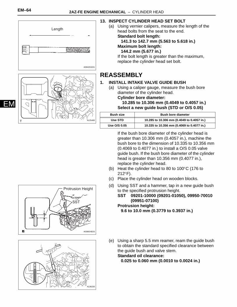
EM–64 2AZ-FE ENGINE MECHANICAL – CYLINDER HEAD
EM
13. INSPECT CYLINDER HEAD SET BOLT(a) Using vernier calipers, measure the length of the
head bolts from the seat to the end.Standard bolt length:
141.3 to 142.7 mm (5.563 to 5.618 in.)Maximum bolt length:
144.2 mm (5.677 in.)If the bolt length is greater than the maximum, replace the cylinder head set bolt.
REASSEMBLY1. INSTALL INTAKE VALVE GUIDE BUSH
(a) Using a caliper gauge, measure the bush bore diameter of the cylinder head.Cylinder bore diameter:
10.285 to 10.306 mm (0.4049 to 0.4057 in.)Select a new guide bush (STD or O/S 0.05)
If the bush bore diameter of the cylinder head is greater than 10.306 mm (0.4057 in.), machine the bush bore to the dimension of 10.335 to 10.356 mm (0.4069 to 0.4077 in.) to install a O/S 0.05 valve guide bush. If the bush bore diameter of the cylinder head is greater than 10.356 mm (0.4077 in.), replace the cylinder head.
(b) Heat the cylinder head to 80 to 100°C (176 to 212°F).
(c) Place the cylinder head on wooden blocks.(d) Using SST and a hammer, tap in a new guide bush
to the specified protrusion height.SST 09201-10000 (09201-01050), 09950-70010
(09951-07100)Protrusion height:
9.6 to 10.0 mm (0.3779 to 0.3937 in.)
(e) Using a sharp 5.5 mm reamer, ream the guide bush to obtain the standard specified clearance between the guide bush and valve stem.Standard oil clearance:
0.025 to 0.060 mm (0.0010 to 0.0024 in.)
Length
A094201E01
A131495
Bush size Bush bore diameter
Use STD 10.285 to 10.306 mm (0.4049 to 0.4057 in.)
Use O/S 0.05 10.335 to 10.356 mm (0.4069 to 0.4077 in.)
SST
Protrusion Height
A036634E03
A136150

2AZ-FE ENGINE MECHANICAL – CYLINDER HEAD EM–65
M
E2. INSTALL EXHAUST VALVE GUIDE BUSH(a) Using a caliper gauge, measure the bush bore
diameter of the cylinder head.Diameter:
10.285 to 10.306 mm (0.4049 to 0.4057 in.)Select a new guide bush (STD or O/S 0.05)
If the bush bore diameter of the cylinder head is greater than 10.306 mm (0.4057 in.), machine the bush bore to the dimension of 10.335 to 10.356 mm (0.4069 to 0.4077 in.) to install a O/S 0.05 valve guide bush. If the bush bore diameter of the cylinder head is greater than 10.356 mm (0.4077 in.), replace the cylinder head.
(b) Heat the cylinder head to 80 to 100°C (176 to 212°F).
(c) Place the cylinder head on wooden blocks.(d) Using SST and a hammer, tap in a new guide bush
to the specified protrusion height.SST 09201-10000 (09201-01050), 09950-70010
(09951-07100)Protrusion height:
9.6 to 10.0 mm (0.3779 to 0.3937 in.)
(e) Using a sharp 5.5 mm reamer, ream the guide bush to obtain the standard specified clearance between the guide bush and valve stem.Standard oil clearance:
0.030 to 0.065 mm (0.0012 to 0.0026 in.)
A124782
Bush size Bush bore diameter
Use STD 10.285 to 10.306 mm (0.4049 to 0.4057 in.)
Use O/S 0.05 10.335 to 10.356 mm (0.4069 to 0.4077 in.)
SST
Protrusion Height
A036635E03
A124783

EM–66 2AZ-FE ENGINE MECHANICAL – CYLINDER HEAD
EM
3. INSTALL RING W/HEAD PIN(a) Using a plastic-faced hammer, tap in a new ring pin
to the specified protrusion height.Protrusion height:
3 mm (0.12 in.)4. INSTALL STUD BOLT
NOTICE:If the stud bolt is deformed or the threads are damaged, replace it.
Upper Side:
11 mm (0.43 in.)
8 mm (0.31 in.) 3 mm (0.12 in.)A128230E01

2AZ-FE ENGINE MECHANICAL – CYLINDER HEAD EM–67
M
E(a) Using E5 and E7 "torx" sockets, install the stud bolts.
Torque: Bolt A5.0 N*m (51 kgf*cm, 44 in.*lbf)Bolt B5.0 N*m (51 kgf*cm, 44 in.*lbf)Bolt C9.5 N*m (97 kgf*cm, 84 in.*lbf)Bolt D9.5 N*m (97 kgf*cm, 84 in.*lbf)
Front Side:
A
Upper Side:
B
Intake Side:
C D
12 mm (0.47 in.)
33 mm (1.30 in.)
9 mm (0.35 in.)
A (M6) B (M6)
12 mm (0.47 in.)
46.5 mm (1.83 in.)
12 mm (0.47 in.)
C (M8)
24 mm (0.94 in.)
49.5 mm (1.95 in.)
13 mm (0.51 in.)
D (M8)
13 mm (0.51 in.)
37.5 mm (1.48 in.)
18 mm (0.71 in.)
Exhaust Side:
A
B
A128231E01
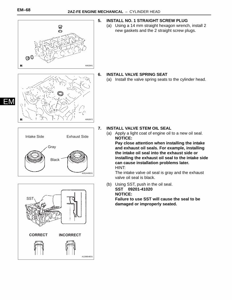
EM–68 2AZ-FE ENGINE MECHANICAL – CYLINDER HEAD
EM
5. INSTALL NO. 1 STRAIGHT SCREW PLUG(a) Using a 14 mm straight hexagon wrench, install 2
new gaskets and the 2 straight screw plugs.
6. INSTALL VALVE SPRING SEAT(a) Install the valve spring seats to the cylinder head.
7. INSTALL VALVE STEM OIL SEAL(a) Apply a light coat of engine oil to a new oil seal.
NOTICE:Pay close attention when installing the intake and exhaust oil seals. For example, installing the intake oil seal into the exhaust side or installing the exhaust oil seal to the intake side can cause installation problems later.HINT:The intake valve oil seal is gray and the exhaust valve oil seal is black.
(b) Using SST, push in the oil seal.SST 09201-41020NOTICE:Failure to use SST will cause the seal to be damaged or improperly seated.
A062841
A062872
Intake Side
Gray
Black
Exhaust Side
A052449E01
SST
CORRECT INCORRECT
A129854E01

2AZ-FE ENGINE MECHANICAL – CYLINDER HEAD EM–69
M
E8. INSTALL INTAKE VALVE(a) Apply a sufficient coat of engine oil to the tip area of
the intake valve shown in the illustration.(b) Install the valve, compression spring and spring
retainer to the cylinder head.NOTICE:Install the same parts in the same combination to the original locations.
(c) Using SST and wooden blocks, compress the spring and install the 2 retainer locks.SST 09202-70020 (09202-00010)
(d) Using a 5 mm pin punch and plastic hammer, lightly tap the valve stem tip to ensure a proper fit.NOTICE:Be careful not to damage the valve stem tip.
9. INSTALL EXHAUST VALVE(a) Apply a sufficient coat of engine oil to the tip area of
the exhaust valve shown in the illustration.(b) Install the valve, compression spring and spring
retainer to the cylinder head.NOTICE:Install the same parts in the same combination to the original locations.
(c) Using SST and wooden blocks, compress the spring and install the 2 retainer locks.SST 09202-70020 (09202-00010)
30 mm (1.18 in.) or more
A094935E04
Wooden Block
SST
A128225E01
5 mm Pin PunchA036640E01
30 mm (1.18 in.) or moreA094936E03
SST
Wooden BlockA128226E01

EM–70 2AZ-FE ENGINE MECHANICAL – CYLINDER HEAD
EM
(d) Using a 5 mm pin punch and plastic hammer, lightly tap the valve stem tip to ensure a proper fit.NOTICE:Be careful not to damage the valve stem tip.
10. INSTALL VALVE LIFTER(a) Assemble the valve lifter and the tip of the valve
stem with a light coat of engine oil applied.NOTICE:Install the valve lifters in their original places.
INSTALLATION1. INSTALL CYLINDER HEAD GASKET
(a) Place a new gasket on the cylinder block surface with the Lot No. stamp facing upward.NOTICE:• Remove any oil from the contact surface.• Make sure that the gasket is installed in the
correct direction.2. INSTALL CYLINDER HEAD SUB-ASSEMBLY
HINT:The cylinder head bolts are tightened in 2 progressive steps.(a) Apply a light coat of engine oil to the bolt threads
and the area beneath the bolt heads that come in contact with the washers.
(b) Install the bolts and plate washers to the cylinder head.NOTICE:Do not drop the washers into the cylinder head.
(c) Using several steps, uniformly install and tighten the 10 cylinder head set bolts and plate washers with a 10 mm bi-hexagon wrench in the order shown in the illustration.Torque: 70 N*m (714 kgf*cm, 52 ft.*lbf)
5 mm Pin PunchA036641E01
A062842E01
Lot No.
A126929E01
1
5
9
7
3
4
6
10
8
2 F050595E03

2AZ-FE ENGINE MECHANICAL – CYLINDER HEAD EM–71
M
E(d) Mark the front side of the cylinder head bolt with paint.
(e) Retighten the cylinder head bolts 90° in the sequence shown in the illustration.
(f) Check that the paint mark is now at a 90° angle to the front.
3. CONNECT ENGINE WIRE(a) Connect the ground cable with the bolt.
Torque: 8.4 N*m (86 kgf*cm, 74 in.*lbf)(b) Connect the camshaft position sensor connector.(c) Connect the engine coolant temperature sensor
connector.(d) Connect the engine oil pressure switch connector.(e) Connect the radio setting condenser connector.
4. CONNECT RADIATOR HOSE INLET (See page EM-118)
5. INSTALL NO. 2 CAMSHAFT BEARING(a) Install the No. 2 camshaft bearing.
6. INSTALL CAMSHAFT TIMING OIL CONTROL VALVE ASSEMBLY (See page ES-406)
7. INSTALL CAMSHAFTS(a) Apply a light coat of engine oil to the journal portion
of the camshaft.
(b) Place the 2 camshafts on the cylinder head with the No. 1 cam lobes facing the directions shown in the illustration.
(c) Examine the front marks and numbers, and check that the order is as shown in the illustration. Then install the bearing caps onto the cylinder head.
(d) Apply a light coat of engine oil to the threads and under the heads of the bearing cap bolts.
Engine Front90°
Paint MarkA098364E01
A098748E01
A128879
No. 1 Cam Lobe
F050592E01
F050591E01

EM–72 2AZ-FE ENGINE MECHANICAL – CYLINDER HEAD
EM
(e) Using several steps, uniformly tighten the 20 bearing cap bolts in the sequence shown in the illustration.Torque: No. 1 and No. 2 bearing cap
30 N*m (301 kgf*cm, 22 ft.*lbf)No. 3 bearing cap9.0 N*m (92 kgf*cm, 80 in.*lbf)
8. INSTALL CHAIN SUB-ASSEMBLYHINT:See page EM-27.
9. INSTALL EXHAUST MANIFOLD CONVERTER SUB-ASSEMBLY (See page EM-109)
10. INSTALL NO. 2 MANIFOLD STAY (See page EM-110)11. INSTALL MANIFOLD STAY (See page EM-111)12. INSTALL OIL LEVEL GAUGE GUIDE (See page EM-
111)13. INSTALL OIL LEVEL GAUGE SUB-ASSEMBLY14. INSTALL GENERATOR ASSEMBLY (See page CH-19)15. INSTALL V-RIBBED BELT (See page EM-6)16. INSTALL NO. 2 ENGINE MOUNTING BRACKET RH
(See page EM-118)17. INSTALL ENGINE MOVING CONTROL ROD SUB-
ASSEMBLY (See page EM-119)18. INSTALL NO. 2 ENGINE MOUNTING STAY RH (See
page EM-119)19. INSTALL FRONT EXHAUST PIPE ASSEMBLY
HINT:See page EX-3.
20. INSTALL NO. 1 INTAKE MANIFOLD INSULATOR (See page EM-111)
21. INSTALL INTAKE AIR CONTROL VALVE (For PZEV) (See page IT-7)
22. INSTALL INTAKE MANIFOLD (See page ES-425)23. INSTALL FUEL DELIVERY PIPE WITH INJECTOR
(See page FU-15)24. CONNECT FUEL TUBE SUB-ASSEMBLY (See page
FU-16)25. INSTALL THROTTLE BODY ASSEMBLY (See page
ES-418)26. INSTALL BATTERY (See page EM-119)27. REMOVE AIR CLEANER CASE SUB-ASSEMBLY (See
page EM-120)28. INSTALL AIR CLEANER CAP SUB-ASSEMBLY (See
page ES-419)
No. 1
No. 2
12
56
9
3478
1017
18
19201112
16
1514
13
F050596E05

2AZ-FE ENGINE MECHANICAL – CYLINDER HEAD EM–73
M
E29. INSTALL AIR CLEANER INLET ASSEMBLY (See page EM-120)
30. INSTALL COWL TOP PANEL OUTER SUB-ASSEMBLY (See page ES-426)
31. INSTALL WINDSHIELD WIPER LINK ASSEMBLYHINT:See page WW-13.
32. CONNECT CABLE FROM NEGATIVE BATTERY TERMINAL (See page EM-120)
33. ADD ENGINE OIL34. CHECK FOR FUEL LEAKS (See page FU-9)35. ADD COOLANT (See page CO-5)36. CHECK FOR ENGINE COOLANT LEAKS (See page
CO-1)37. CHECK FOR ENGINE OIL LEAKS38. CHECK FOR EXHAUST GAS LEAKS39. INSPECT IGNITION TIMING (See page EM-1)40. INSPECT IDLE SPEED (See page EM-2)41. INSPECT COMPRESSION (See page EM-3)42. INSPECT CO/HC (See page EM-3)43. INSTALL NO. 1 ENGINE COVER SUB-ASSEMBLY
(See page EM-121)44. INSTALL FRONT FENDER APRON SEAL RH45. INSTALL ENGINE UNDER COVER LH46. INSTALL ENGINE UNDER COVER RH47. INSTALL FRONT WHEEL RH (See page EM-120)

EM–74 2AZ-FE ENGINE MECHANICAL – ENGINE FRONT OIL SEAL
EM
ENGINE2AZ-FE ENGINE MECHANICALENGINE FRONT OIL SEALCOMPONENTS
CRANKSHAFT PULLEY
TIMING CHAIN CASE OIL SEAL
V-RIBBED BELT
N*m (kgf*cm, ft.*lbf) : Specified torque Non-reusable part
TMMK: 170 (1,733, 125) TMC: 180 (1,835, 133)
ENGINE UNDER COVER RH
ENGINE UNDER COVER LH
FRONT FENDER APRON SEAL RH
A134924E03

2AZ-FE ENGINE MECHANICAL – ENGINE FRONT OIL SEAL EM–75
M
EREMOVAL1. REMOVE FRONT WHEEL RH2. REMOVE FRONT FENDER APRON SEAL RH3. REMOVE ENGINE UNDER COVER LH4. REMOVE ENGINE UNDER COVER RH5. REMOVE V-RIBBED BELT (See page EM-6)6. REMOVE CRANKSHAFT PULLEY
(a) TMMK made:(1) Using SST, fix the pulley in place and loosen
the pulley bolt.SST 09960-10010 (09962-01000, 09963-
01000)
(2) Using SST, remove the pulley bolt and pulley.SST 09950-40011 (09951-04010, 09952-
04010, 09953-04030, 09955-04041, 09957-04010, 09954-04010, 91111-51014)
(b) TMC made:(1) Using SST, fix the pulley in place and loosen
the pulley bolt.SST 09213-54015 (91651-60855), 09330-
00021
(2) Using SST, remove the pulley bolt and pulley.SST 09950-50013 (09951-05010, 09952-
05010, 09953-05020, 09954-05021), 09950-40011 (09957-04010)
HINT:If necessary, remove the pulley and pulley bolt using SST.
SST
A062057E02
Hooking Point
SSTA062058E03
SSTSST
A013697E02
SST
A124860E01

EM–76 2AZ-FE ENGINE MECHANICAL – ENGINE FRONT OIL SEAL
EM
7. REMOVE TIMING CHAIN CASE OIL SEAL(a) Using a knife, cut off the oil seal lip.(b) Using a screwdriver with the tip taped, pry out the oil
seal.NOTICE:After the removal, check the crankshaft for damage. If it is damaged, smooth the surface with 400-grit sandpaper.
Cut Position
A112529E02

2AZ-FE ENGINE MECHANICAL – ENGINE FRONT OIL SEAL EM–77
M
EINSTALLATION1. INSTALL TIMING CHAIN CASE OIL SEAL
(a) Apply MP grease to a new oil seal lip.NOTICE:Keep the lip free from foreign matter.
(b) Using SST and a hammer, tap in the oil seal until its surface is flush with the rear oil seal retainer edge.SST 09223-22010NOTICE:Wipe off extra grease from the crankshaft.
2. INSTALL CRANKSHAFT PULLEY(a) TMMK made:
(1) Align the pulley set key with the key groove of the pulley.
(2) Using SST, fix the pulley in place and tighten the bolt.SST 09960-10010 (09962-01000, 09963-
01000)Torque: 170 N*m (1,733 kgf*cm, 125 ft.*lbf)
(b) TMC made:(1) Align the pulley set key with the key groove of
the pulley.
(2) Using SST, fix the pulley in place and tighten the bolt.SST 09213-54015 (91651-60855), 09330-
00021Torque: 180 N*m (1,835 kgf*cm, 133 ft.*lbf)
3. INSTALL V-RIBBED BELT (See page EM-6)4. INSTALL ENGINE UNDER COVER LH5. INSTALL ENGINE UNDER COVER RH6. INSTALL FRONT FENDER APRON SEAL RH7. INSTALL FRONT WHEEL RH8. CHECK FOR ENGINE OIL LEAKS
A032663
SST
A062057E02
SSTSST
A013697E03
2AZ-FE ENGINE MECHANICAL – ENGINE REAR OIL SEAL EM–77
M
EENGINE2AZ-FE ENGINE MECHANICALENGINE REAR OIL SEALCOMPONENTS
ENGINE REAR OIL SEAL
N*m (kgf*cm, ft.*lbf) : Specified torque
Non-reusable part
130 (1,330, 96)
19 (195, 14)
CLUTCH COVER ASSEMBLY
CLUTCH DISC ASSEMBLY
FLYWHEEL SUB-ASSEMBLY
M/T:
x8
x6
A136909E01

EM–78 2AZ-FE ENGINE MECHANICAL – ENGINE REAR OIL SEAL
EM
ENGINE REAR OIL SEALN*m (kgf*cm, ft.*lbf) : Specified torque
Non-reusable part
98 (1,000, 72)41 (418, 30)
DRIVE PLATE & RING GEAR SUB-ASSEMBLY
FRONT SPACER
REAR SPACER
A/T:
x6 x8
A136910E01
2AZ-FE ENGINE MECHANICAL – ENGINE REAR OIL SEAL EM–79
M
EREMOVAL1. SEPARATE AUTOMATIC TRANSAXLE ASSEMBLY
(for Automatic Transaxle)HINT:See page AX-162.
2. SEPARATE MANUAL TRANSAXLE ASSEMBLY (for Manual Transaxle)HINT:See page MX-24.
3. REMOVE DRIVE PLATE & RING GEAR SUB-ASSEMBLY (for Automatic Transaxle)(a) TMMK made:
(1) Using SST, hold the crankshaft.SST 09960-10010 (09962-01000, 09963-
01000)
(b) TMC made:(1) Using SST, hold the crankshaft.
SST 09213-54015 (91651-60855), 09330-00021
(c) Remove the 8 bolts, rear spacer, drive plate and front spacer.
4. REMOVE CLUTCH COVER ASSEMBLY (for Manual Transaxle) (See page CL-32)
5. REMOVE CLUTCH DISC ASSEMBLY (for Manual Transaxle) (See page CL-32)
6. REMOVE FLYWHEEL SUB-ASSEMBLY (for Manual Transaxle)(a) TMMK made:
(1) Using SST, hold the crankshaft.SST 09960-10010 (09962-01000, 09963-
01000)
SST
A062061E01
SSTA126932E01
A091018
SST
A062061E01

EM–80 2AZ-FE ENGINE MECHANICAL – ENGINE REAR OIL SEAL
EM
(b) TMC made:(1) Using SST, hold the crankshaft.
SST 09213-54015 (91651-60855), 09330-00021
(c) Remove the 8 bolts and flywheel.
7. REMOVE ENGINE REAR OIL SEAL(a) Using a knife, cut through the oil seal lip.(b) Using a screwdriver with its tip taped, pry out the oil
seal.NOTICE:After the removal, check the crankshaft for damage. If it is damaged, smooth the surface with 400-grit sandpaper.
SSTA126932E01
A091020E01
Cut positionA128873E01

2AZ-FE ENGINE MECHANICAL – ENGINE REAR OIL SEAL EM–81
M
EINSTALLATION1. INSTALL ENGINE REAR OIL SEAL
(a) Apply MP grease to a new oil seal lip.NOTICE:Keep the lip free from foreign matter.
(b) Using SST and a hammer, tap in the oil seal until its surface is flush with the rear oil seal retainer edge.SST 09223-15030, 09950-70010 (09951-07100)NOTICE:Wipe off extra grease from the crankshaft.
2. INSTALL FLYWHEEL SUB-ASSEMBLY (for Manual Transaxle)(a) TMMK made:
(1) Using SST, hold the crankshaft.SST 09960-10010 (09962-01000, 09963-
01000)
(b) TMC made:(1) Using SST, hold the crankshaft.
SST 09213-54015 (91651-60855), 09330-00021
(c) Clean the bolt and the bolt hole.(d) Apply adhesive to 2 or 3 threads of the bolt end.
Adhesive:Part No. 08833-00070, THREE BOND or equivalent
(e) Install the flywheel with the 8 bolts. Uniformly tighten the 8 bolts in the sequence shown in the illustration.Torque: 130 N*m (1,330 kgf*cm, 96 ft.*lbf)
3. INSTALL CLUTCH DISC ASSEMBLY (for Manual Transaxle) (See page CL-34)
4. INSTALL CLUTCH COVER ASSEMBLY (for Manual Transaxle) (See page CL-34)
SST
A128874E01
SST
A062061E01
SSTA126932E01
A060816

EM–82 2AZ-FE ENGINE MECHANICAL – ENGINE REAR OIL SEAL
EM
5. INSTALL DRIVE PLATE & RING GEAR SUB-ASSEMBLY (for Automatic Transaxle)(a) TMMK made:
(1) Using SST, hold the crankshaft.SST 09960-10010 (09962-01000, 09963-
01000)
(b) TMC made:(1) Using SST, hold the crankshaft.
SST 09213-54015 (91651-60855), 09330-00021
(c) Clean the bolt and the bolt hole.(d) Apply adhesive to 2 or 3 threads of the bolt end.
Adhesive:Part No. 08833-00070, THREE BOND or equivalent
(e) Install the front spacer, drive plate and rear spacer with the 8 bolts. Uniformly tighten the 8 bolts in the sequence shown in the illustration.Torque: 98 N*m (1,000 kgf*cm, 72 ft.*lbf)
6. INSTALL MANUAL TRANSAXLE ASSEMBLY (for Manual Transaxle)HINT:See page MX-27.
7. INSTALL AUTOMATIC TRANSAXLE ASSEMBLY (for Automatic Transaxle)HINT:See page AX-168.
SST
A062061E01
SSTA126932E01
1
2
3
45
6
78
A112224E01

2AZ-FE ENGINE MECHANICAL – ENGINE ASSEMBLY EM–83
M
EENGINE2AZ-FE ENGINE MECHANICALENGINE ASSEMBLYCOMPONENTS
COWL TOP PANEL OUTER SUB-ASSEMBLY
FRONT WIPER ARM AND BLADE ASSEMBLY RH
FRONT WIPER ARM AND BLADE ASSEMBLY LH
FRONT FENDER TO COWL SIDE SEAL RH
COWL TOP VENTILATOR LOUVER SUB-ASSEMBLY
FRONT FENDER TO COWL SIDE SEAL LH
N*m (kgf*cm, ft.*lbf) : Specified torque
5.0 (51, 44 in.*lbf)
7.5 (77, 66 in.*lbf)85 (867, 63)
20 (204, 15)
WINDSHIELD WIPER LINK ASSEMBLY
A136912E01

EM–84 2AZ-FE ENGINE MECHANICAL – ENGINE ASSEMBLY
EM
FRONT FENDER APRON SEAL RH
N*m (kgf*cm, ft.*lbf) : Specified torque
ENGINE MOVING CONTROL ROD SUB-ASSEMBLY
NO. 1 ENGINE COVER SUB-ASSEMBLY
NO. 2 ENGINE MOUNTING BRACKET RH
NO. 2 ENGINE MOUNTING STAY RH
V-RIBBED BELT
64 (653, 47)
64 (653, 47)
52 (531, 38)
52 (531, 38)
21 (214, 15)
9.0 (92, 80 in.*lbf)
9.8 (100, 87 in.*lbf)
GENERATOR ASSEMBLY
A134948E01

2AZ-FE ENGINE MECHANICAL – ENGINE ASSEMBLY EM–85
M
EBATTERY TRAY
9.0 (92, 80 in.*lbf)
AIR CLEANER CAP SUB-ASSEMBLY
AIR CLEANER CASE SUB-ASSEMBLY
AIR CLEANER INLET ASSEMBLYBATTERY
ENGINE UNDER COVER RH
ENGINE UNDER COVER LH
R/B COVER
N*m (kgf*cm, ft.*lbf) : Specified torque
5.0 (51, 44 in.*lbf)
3.5 (36, 31 in.*lbf)
5.0 (51, 44 in.*lbf)
A134915E01

EM–86 2AZ-FE ENGINE MECHANICAL – ENGINE ASSEMBLY
EM
NO. 1 OIL RESERVOIR TO PUMP HOSE NO. 1 VACUUM HOSE CONNECTOR
OIL COOLER INLET HOSEOIL COOLER OUTLET HOSE
RETURN TUBE SUB-ASSEMBLY
TRANSMISSION CONTROL CABLE ASSEMBLY (for A/T)
TRANSMISSION CONTROL CABLE ASSEMBLY
M/T:
CLUTCH ACCUMULATOR ASSEMBLY
CLUTCH RELEASE CYLINDER ASSEMBLY
N*m (kgf*cm, ft.*lbf) : Specified torque Non-reusable part
12 (120, 9)
13 (133, 10)
25 (250, 18)
12 (120, 9)
CLIP
CLIP
HEATER INLET WATER HOSE
HEATER OUTLET WATER HOSERADIATOR HOSE INLET
RADIATOR HOSE OUTLET
COMPRESSOR AND MAGNETIC CLUTCH
A134916E01

2AZ-FE ENGINE MECHANICAL – ENGINE ASSEMBLY EM–87
M
EFRONT AXLE HUB NUT LH
FRONT EXHAUST PIPE ASSEMBLY
TIE ROD ASSEMBLY LH
N*m (kgf*cm, ft.*lbf) : Specified torque Non-reusable part
294 (3,000, 217)
75 (755, 55)
49 (500, 36)
35 (357, 26)
33 (337, 24) 33 (337, 24)
62 (633, 46)
56 (571, 41)
8.0 (82, 71 in.*lbf)
EXHAUST PIPE GASKET
EXHAUST PIPE GASKET
REAR EXHAUST PIPE NO. 1 SUPPORT BRACKET
FRONT EXHAUST PIPE NO. 1 SUPPORT BRACKET
DRIVE SHAFT ASSEMBLY LH
74 (755, 55)
19 (194, 13)
STEERING SLIDING YOKE
FRONT SUSPENSION LOWER NO. 1 ARM LH
FRONT SPEED SENSOR LH
NO. 1 EXHAUST PIPE SUPPORT BRACKET
COTTER PIN
A134917E01

EM–88 2AZ-FE ENGINE MECHANICAL – ENGINE ASSEMBLY
EM
FRAME SIDE RAIL PLATE SUB-ASSEMBLY RH
FRAME SIDE RAIL PLATE SUB-ASSEMBLY LH
FRAME SUSPENSION MEMBER BRACE REAR LH
FRAME SUSPENSION MEMBER BRACE REAR RH
N*m (kgf*cm, ft.*lbf) : Specified torque
95 (969, 70)
87 (888, 64)
85 (867, 63)
85 (867, 63)32 (326, 24)
32 (326, 24)
95 (969, 70)
43 (439, 32)
54 (551, 40)
A/T:
ENGINE MOUNTING BRACKET RH
FRONT FRAME ASSEMBLY
VANE PUMP ASSEMBLY
x3
A138330E01

2AZ-FE ENGINE MECHANICAL – ENGINE ASSEMBLY EM–89
M
EN*m (kgf*cm, ft.*lbf) : Specified torque
87 (888, 64) 143 (1,459, 105)
32 (326, 24)
85 (867, 63)
85 (867, 63)32 (326, 24)
43 (439, 32)
89 (910, 66)
64 (653, 47)54 (551, 40)
95 (969, 70)
NO. 2 ENGINE MOUNTING BRACKET REAR
FRAME SUSPENSION MEMBER BRACE REAR LH
FRAME SUSPENSION MEMBER BRACE REAR RH
FRAME SIDE RAIL PLATE SUB-ASSEMBLY LH
FRAME SIDE RAIL PLATE SUB-ASSEMBLY RH
M/T:
ENGINE MOUNTING BRACKET RH
FRONT FRAME ASSEMBLY
VANE PUMP ASSEMBLY
A138333E01
EM–90 2AZ-FE ENGINE MECHANICAL – ENGINE ASSEMBLY
EM
N*m (kgf*cm, ft.*lbf) : Specified torque Non-reusable part
64 (653, 47)
64 (650, 47)
46 (470, 34)
39 (398, 29)
98 (1,000, 72)
44 (450, 32)
41 (418, 30)
AUTOMATIC TRANSAXLE ASSEMBLY
ENGINE WIRE
HOLE SNAP RING
FLYWHEEL HOUSING UNDER COVER
FRONT SPACER
REAR SPACER
SNAP RING
A/T:
DRIVE PLATE & RING GEAR SUB-ASSEMBLY
DRIVE SHAFT BEARING BRACKET
FRONT DRIVE SHAFT ASSEMBLY LH
STARTER ASSEMBLY
FRONT DRIVE SHAFT ASSEMBLY RH
A139203E01

2AZ-FE ENGINE MECHANICAL – ENGINE ASSEMBLY EM–91
M
EENGINE WIRE
MANUAL TRANSAXLE ASSEMBLY
N*m (kgf*cm, ft.*lbf) : Specified torque Non-reusable part
64 (653, 47)
39 (398, 29)
46 (470, 34)
64 (650, 47)
46 (470, 34)
64 (650, 47)
19 (195, 14)130 (1,330, 96)
44 (450, 32)
HOLE SNAP RING
SNAP RING
M/T:
CLUTCH COVER ASSEMBLY
CLUTCH DISC ASSEMBLY
DRIVE SHAFT BEARING BRACKET
FLYWHEEL SUB-ASSEMBLY
FRONT DRIVE SHAFT ASSEMBLY LH
FRONT DRIVE SHAFT ASSEMBLY RH
STARTER ASSEMBLY
A137255E01

EM–92 2AZ-FE ENGINE MECHANICAL – ENGINE ASSEMBLY
EM
FUEL DELIVERY PIPE WITH INJECTOR
SPACER
N*m (kgf*cm, ft.*lbf) : Specified torque Non-reusable part
20 (204, 15)
30 (306, 22)
12 (122, 9)
44 (449, 32)
44 (449, 32)
44 (449, 32)
37 (378, 27)
INTAKE MANIFOLD
MANIFOLD STAY
NO. 2 MANIFOLD STAY
NO. 1 INTAKE MANIFOLD INSULATOR
GASKET
GASKET
VENTILATION HOSE
VENTILATION HOSE NO. 2
For PZEV:
EXHAUST MANIFOLD CONVERTER SUB-ASSEMBLY
x5
INSURATOR
NO. 1 MANIFOLD CONVERTER INSULATOR
INTAKE AIR CONTROL VALVE (For PZEV)
A136908E02
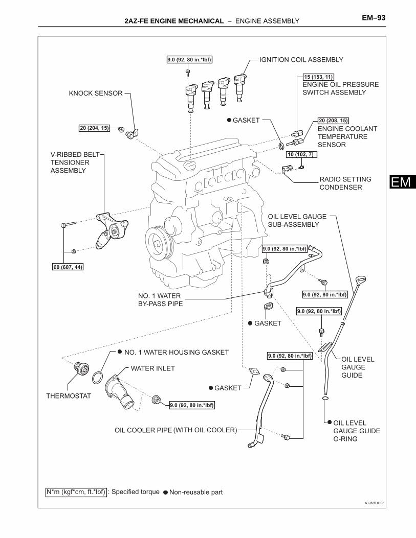
2AZ-FE ENGINE MECHANICAL – ENGINE ASSEMBLY EM–93
M
EIGNITION COIL ASSEMBLY
V-RIBBED BELT TENSIONER ASSEMBLY
N*m (kgf*cm, ft.*lbf) : Specified torque Non-reusable part
9.0 (92, 80 in.*lbf)
9.0 (92, 80 in.*lbf)
9.0 (92, 80 in.*lbf)
9.0 (92, 80 in.*lbf)
9.0 (92, 80 in.*lbf)
9.0 (92, 80 in.*lbf)
60 (607, 44)
15 (153, 11)
20 (204, 15)20 (208, 15)
GASKET
NO. 1 WATER HOUSING GASKET
GASKET
WATER INLET
THERMOSTAT
OIL COOLER PIPE (WITH OIL COOLER)
ENGINE COOLANT TEMPERATURE SENSOR
ENGINE OIL PRESSURE SWITCH ASSEMBLYKNOCK SENSOR
OIL LEVEL GAUGE SUB-ASSEMBLY
OIL LEVEL GAUGE GUIDE O-RING
OIL LEVEL GAUGE GUIDE
NO. 1 WATER BY-PASS PIPE
GASKET
RADIO SETTING CONDENSER
10 (102, 7)
A136911E02

EM–94 2AZ-FE ENGINE MECHANICAL – ENGINE ASSEMBLY
EM
REMOVAL1. DISCHARGE FUEL SYSTEM PRESSURE
HINT:See page FU-1.
2. DISCONNECT CABLE FROM NEGATIVE BATTERY TERMINAL
3. PLACE FRONT WHEELS FACING STRAIGHT AHEAD4. REMOVE FRONT WHEELS5. REMOVE ENGINE UNDER COVER LH6. REMOVE ENGINE UNDER COVER RH7. REMOVE FRONT FENDER APRON SEAL RH8. DRAIN ENGINE OIL (See page LU-4)9. DRAIN ENGINE COOLANT (See page CO-5)10. DRAIN AUTOMATIC TRANSAXLE FLUID (for
Automatic Transaxle) (See page AX-162)11. DRAIN MANUAL TRANSAXLE OIL (for Manual
Transaxle) (See page MX-5)12. DRAIN BRAKE FLUID (for Manual Transaxle) (See
page BR-28)13. REMOVE WINDSHIELD WIPER LINK ASSEMBLY
HINT:See page WW-9.
14. REMOVE COWL TOP PANEL OUTER SUB-ASSEMBLY (See page ES-424)
15. REMOVE NO. 1 ENGINE COVER SUB-ASSEMBLY(a) Remove the 2 nuts and cover.
16. REMOVE V-RIBBED BELT (See page EM-6)
17. REMOVE AIR CLEANER INLET ASSEMBLY(a) Remove the 2 bolts, clamp and air cleaner inlet.
18. REMOVE AIR CLEANER CAP SUB-ASSEMBLY (See page ES-416)
A134904
A134903

2AZ-FE ENGINE MECHANICAL – ENGINE ASSEMBLY EM–95
M
E19. REMOVE AIR CLEANER CASE SUB-ASSEMBLY(a) Disconnect the hose clamp.(b) Remove the 3 bolts and air cleaner case.
20. REMOVE BATTERY(a) Loosen the bolt and nut, and remove the battery
clamp.(b) Remove the battery and battery tray.
21. REMOVE NO. 2 ENGINE MOUNTING STAY RH(a) Remove the 2 bolts and No. 2 mounting stay RH.
22. REMOVE ENGINE MOVING CONTROL ROD SUB-ASSEMBLY(a) Remove the bolt and disconnect the ground cable.
A134905
A134906
A134912
A134909

EM–96 2AZ-FE ENGINE MECHANICAL – ENGINE ASSEMBLY
EM
(b) Remove the 3 bolts and the engine moving control rod with bracket.
23. REMOVE NO. 2 ENGINE MOUNTING BRACKET RH(a) Remove the 3 bolts and No. 2 mounting bracket RH.
24. DISCONNECT NO. 1 VACUUM HOSE CONNECTOR(a) Remove the clamp and disconnect the vacuum
hose connector.
25. DISCONNECT RADIATOR HOSE INLET(a) Remove the clamp and disconnect the radiator hose
inlet.
26. DISCONNECT RADIATOR HOSE OUTLET(a) Remove the clamp and disconnect the radiator hose
outlet.
27. DISCONNECT OIL COOLER INLET HOSE (for Automatic Transaxle) (See page CO-22)
28. DISCONNECT OIL COOLER OUTLET HOSE (for Automatic Transaxle) (See page CO-23)
A134910
A134911
A134908
A134907
A127545

2AZ-FE ENGINE MECHANICAL – ENGINE ASSEMBLY EM–97
M
E29. DISCONNECT HEATER INLET WATER HOSE(a) Disconnect the heater inlet water hose.
30. DISCONNECT HEATER OUTLET WATER HOSE(a) Disconnect the heater outlet water hose.
31. REMOVE ECMHINT:See page ES-432.
32. DISCONNECT ENGINE WIRE(a) Disconnect the engine wire from the engine room
relay block.(1) Remove the nut and separate the wire harness.(2) Using a screwdriver, unlock the engine room R/
B. Pull the engine room R/B upward.(3) Disconnect the engine wire connectors.
(b) Remove the clamp from the bracket.
A124832
A124831
A132975
A134913

EM–98 2AZ-FE ENGINE MECHANICAL – ENGINE ASSEMBLY
EM
(c) Remove the 2 bolts and clamp from the body.
33. DISCONNECT TRANSMISSION CONTROL CABLE ASSEMBLY (for Automatic Transaxle)(a) Remove the clip and nut, and separate the control
lever.(b) Separate the clamp and separate the cable from the
transaxle.
34. DISCONNECT TRANSMISSION CONTROL CABLE ASSEMBLY (for Manual Transaxle)(a) Remove the 2 clips and 2 washers and disconnect
the 2 cables from the transaxle.(b) Remove the 2 clips and disconnect the 2 cables
from the control cable bracket.
35. DISCONNECT NO. 1 OIL RESERVOIR TO PUMP HOSE(a) Disconnect the No. 1 oil reservoir to pump hose.
A134914
A132974
C132952
A060072
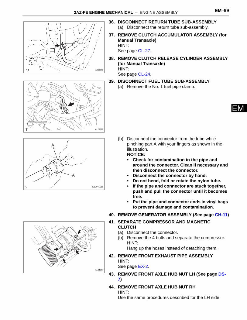
2AZ-FE ENGINE MECHANICAL – ENGINE ASSEMBLY EM–99
M
E36. DISCONNECT RETURN TUBE SUB-ASSEMBLY(a) Disconnect the return tube sub-assembly.
37. REMOVE CLUTCH ACCUMULATOR ASSEMBLY (for Manual Transaxle)HINT:See page CL-27.
38. REMOVE CLUTCH RELEASE CYLINDER ASSEMBLY (for Manual Transaxle)HINT:See page CL-24.
39. DISCONNECT FUEL TUBE SUB-ASSEMBLY(a) Remove the No. 1 fuel pipe clamp.
(b) Disconnect the connector from the tube while pinching part A with your fingers as shown in the illustration.NOTICE:• Check for contamination in the pipe and
around the connector. Clean if necessary and then disconnect the connector.
• Disconnect the connector by hand.• Do not bend, fold or rotate the nylon tube.• If the pipe and connector are stuck together,
push and pull the connector until it becomes free.
• Put the pipe and connector ends in vinyl bags to prevent damage and contamination.
40. REMOVE GENERATOR ASSEMBLY (See page CH-11)41. SEPARATE COMPRESSOR AND MAGNETIC
CLUTCH(a) Disconnect the connector.(b) Remove the 4 bolts and separate the compressor.
HINT:Hang up the hoses instead of detaching them.
42. REMOVE FRONT EXHAUST PIPE ASSEMBLYHINT:See page EX-2.
43. REMOVE FRONT AXLE HUB NUT LH (See page DS-7)
44. REMOVE FRONT AXLE HUB NUT RHHINT:Use the same procedures described for the LH side.
A060073
A129626
A
A
B012941E15
A134944

EM–100 2AZ-FE ENGINE MECHANICAL – ENGINE ASSEMBLY
EM
45. REMOVE FRONT STABILIZER LINK ASSEMBLY LH (See page DS-7)
46. REMOVE FRONT STABILIZER LINK ASSEMBLY RHHINT:Use the same procedures described for the LH side.
47. REMOVE FRONT SPEED SENSOR LH (See page DS-7)
48. REMOVE FRONT SPEED SENSOR RHHINT:Use the same procedures described for the LH side.
49. DISCONNECT TIE ROD ASSEMBLY LH (See page DS-8)
50. DISCONNECT TIE ROD ASSEMBLY RHHINT:Use the same procedures described for the LH side.
51. DISCONNECT FRONT SUSPENSION LOWER NO. 1 ARM LH (See page DS-8)
52. DISCONNECT FRONT SUSPENSION LOWER NO. 1 ARM RHHINT:Use the same procedures described for the LH side.
53. SEPARATE FRONT AXLE ASSEMBLY LH (See page DS-8)
54. SEPARATE FRONT AXLE ASSEMBLY RHHINT:Use the same procedures described for the LH side.
55. REMOVE DRIVE PLATE & TORQUE CONVERTER CLUTCH SETTING BOLT (for Automatic Transaxle) (See page AX-164)
56. REMOVE NO. 1 EXHAUST PIPE SUPPORT BRACKET(a) Remove the 2 bolts and exhaust pipe support
bracket.
57. SEPARATE STEERING SLIDING YOKE (See page PS-40)
58. REMOVE ENGINE ASSEMBLY WITH TRANSAXLE(a) Set the engine lifter.(b) Remove the 4 bolts, 2 nuts and frame side rail plate
RH and LH.
A059877

2AZ-FE ENGINE MECHANICAL – ENGINE ASSEMBLY EM–101
M
E(c) Remove the 4 bolts, 2 nuts and front suspension member brace rear RH and LH.
(d) Carefully remove the engine assembly from the vehicle.
(e) Install the 2 engine hangers as shown in the illustration.Parts No.:
Torque: 38 N*m (387 kgf*cm, 28 ft.*lbf)(f) Using a chain block and an engine sling device,
hang the engine assembly.59. REMOVE VANE PUMP ASSEMBLY
(a) Disconnect the oil pressure switch connector.(b) Loosen the 2 bolts and remove the vane pump from
the engine.
60. REMOVE FRONT FRAME ASSEMBLY(a) A/T:
Remove the nut from the engine mounting insulator LH.
(b) M/T:Remove the bolt from the engine mounting insulator LH.
A059878
No . 1 Engine Hanger No. 2 Engine Hanger
A090847E03
Parts Parts No.
No. 1 Engine hanger 12281-28010
No. 2 Engine hanger 12282-28010
Bolt 91512-61020
A059879
A/T
A052490E01
M/T
A059881E01

EM–102 2AZ-FE ENGINE MECHANICAL – ENGINE ASSEMBLY
EM
(c) Remove the nut from the engine mounting insulator RH.
(d) Remove the bolt from the engine mounting insulator FR.
(e) M/T:Remove the bolt from the engine lateral control rod.
(f) Raise the engine assembly and separate the front frame.
61. REMOVE FRONT DRIVE SHAFT ASSEMBLY LH (See page DS-9)
62. REMOVE FRONT DRIVE SHAFT ASSEMBLY RH (See page DS-9)
63. REMOVE ENGINE WIRE64. REMOVE STARTER ASSEMBLY (for Manual
Transaxle) (See page ST-5)65. REMOVE STARTER ASSEMBLY (for Automatic
Transaxle) (See page ST-5)66. SEPARATE AUTOMATIC TRANSAXLE ASSEMBLY
(for Automatic Transaxle)HINT:See page AX-162.
67. SEPARATE MANUAL TRANSAXLE ASSEMBLY (for Manual Transaxle)HINT:See page MX-24.
68. REMOVE DRIVE PLATE & RING GEAR SUB-ASSEMBLY (for Automatic Transaxle) (See page EM-79)
69. REMOVE CLUTCH COVER ASSEMBLY (for Manual Transaxle) (See page CL-32)
70. REMOVE CLUTCH DISC ASSEMBLY (for Manual Transaxle) (See page CL-32)
A052482
A059880
M/T
A060825E04
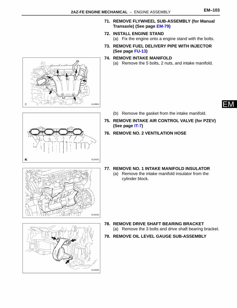
2AZ-FE ENGINE MECHANICAL – ENGINE ASSEMBLY EM–103
M
E71. REMOVE FLYWHEEL SUB-ASSEMBLY (for Manual Transaxle) (See page EM-79)
72. INSTALL ENGINE STAND(a) Fix the engine onto a engine stand with the bolts.
73. REMOVE FUEL DELIVERY PIPE WITH INJECTOR (See page FU-13)
74. REMOVE INTAKE MANIFOLD(a) Remove the 5 bolts, 2 nuts, and intake manifold.
(b) Remove the gasket from the intake manifold.
75. REMOVE INTAKE AIR CONTROL VALVE (for PZEV) (See page IT-7)
76. REMOVE NO. 2 VENTILATION HOSE
77. REMOVE NO. 1 INTAKE MANIFOLD INSULATOR(a) Remove the intake manifold insulator from the
cylinder block.
78. REMOVE DRIVE SHAFT BEARING BRACKET(a) Remove the 3 bolts and drive shaft bearing bracket.
79. REMOVE OIL LEVEL GAUGE SUB-ASSEMBLY
A128862
A134342
A134343
A134945

EM–104 2AZ-FE ENGINE MECHANICAL – ENGINE ASSEMBLY
EM
80. REMOVE OIL LEVEL GAUGE GUIDE(a) Remove the bolt and oil level gauge guide.(b) Remove the O-ring from the oil level gauge guide.
81. REMOVE MANIFOLD STAY(a) Remove the bolt, nut and stay.
82. REMOVE NO. 2 MANIFOLD STAY(a) Remove the bolt, nut and stay.
83. REMOVE EXHAUST MANIFOLD CONVERTER SUB-ASSEMBLY(a) For PZEV:
(1) Disconnect the air-fuel ratio sensor connector.
(2) Remove the 5 nuts, manifold converter and gasket.
A112218
A112193
A112192
A098744E01
A136913

2AZ-FE ENGINE MECHANICAL – ENGINE ASSEMBLY EM–105
M
E(b) Except for PZEV:(1) Remove the 4 bolts and No. 1 insulator.
(2) Disconnect the air-fuel ratio sensor connector.
(3) Remove the 5 nuts, manifold converter and gasket.
84. REMOVE WATER INLET (See page CO-13)85. REMOVE THERMOSTAT (See page CO-13)
86. REMOVE NO. 1 WATER BY-PASS PIPE(a) Remove the bolt, 2 nuts and No. 1 water by-pass
pipe with the gasket.
87. REMOVE OIL COOLER PIPE (w/ Oil Cooler)(a) Remove the bolt, 2 nuts and oil cooler pipe with the
gasket.
A112189
A098744E01
A112190
A112226
A126879

EM–106 2AZ-FE ENGINE MECHANICAL – ENGINE ASSEMBLY
EM
88. REMOVE ENGINE MOUNTING BRACKET RH(a) Remove the 3 bolts and engine mounting bracket
RH.
89. REMOVE V-RIBBED BELT TENSIONER ASSEMBLY(a) Remove the bolt, nut and belt tensioner.
90. REMOVE IGNITION COIL ASSEMBLY(a) Remove the 4 bolts and 4 ignition coils.
91. REMOVE CAMSHAFT TIMING OIL CONTROL VALVE ASSEMBLY (See page ES-405)
92. REMOVE KNOCK SENSOR(a) Disconnect the sensor connector.(b) Remove the nut and sensor.
93. REMOVE RADIO SETTING CONDENSER(a) Remove the bolt and radio setting condenser.
94. REMOVE ENGINE OIL PRESSURE SWITCH ASSEMBLY(a) Using a 24 mm deep socket wrench, remove the
engine oil pressure switch assembly.
A052481
A112212
A112227
A128875

2AZ-FE ENGINE MECHANICAL – ENGINE ASSEMBLY EM–107
M
E95. REMOVE ENGINE COOLANT TEMPERATURE SENSOR(a) Using SST, remove the sensor and gasket.
SST 09817-33190
INSPECTION1. INSPECT INTAKE MANIFOLD
(a) Using a precision straight edge and feeler gauge, measure the surface contacting the cylinder head for warpage.Maximum warpage:
0.20 mm (0.0079 in.)If the warpage is greater than maximum, replace the manifold.
2. INSPECT EXHAUST MANIFOLD CONVERTER SUB-ASSEMBLY(a) Using a precision straight edge and feeler gauge,
measure the surface contacting the cylinder head for warpage.Maximum warpage:
0.70 mm (0.0276 in.)If the warpage is greater than the maximum, replace the manifold.
INSTALLATION1. INSTALL ENGINE COOLANT TEMPERATURE
SENSOR(a) Using SST, install a new gasket and the ECT
sensor.SST 09817-33190Torque: 20 N*m (208 kgf*cm, 15 ft.*lbf)
SST
Gasket
A114367E01
A085564
A124780
SST
Gasket
A114367E01

EM–108 2AZ-FE ENGINE MECHANICAL – ENGINE ASSEMBLY
EM
2. INSTALL ENGINE OIL PRESSURE SWITCH ASSEMBLY(a) Clean the threads of the oil pressure switch. Apply
adhesive to 2 or 3 threads of the oil.Adhesive:
Part No. 08833-00080 THREE BOND 1344 or equivalent
(b) Using a 24 mm deep socket wrench, install the oil pressure switch.Torque: 15 N*m (153 kgf*cm, 11 ft.*lbf)
3. INSTALL RADIO SETTING CONDENSER(a) Install the condenser with the bolt.
Torque: 10 N*m (102 kgf*cm, 7 ft.*lbf)
4. INSTALL KNOCK SENSOR(a) Install the sensor with the nut as shown in the
illustration.Torque: 20 N*m (204 kgf*cm, 15 ft.*lbf)
5. INSTALL CAMSHAFT TIMING OIL CONTROL VALVE ASSEMBLY (See page ES-406)
6. INSTALL IGNITION COIL ASSEMBLY(a) Install the 4 ignition coils with the 4 bolts.
Torque: 9.0 N*m (92 kgf*cm, 80 in.*lbf)
7. INSTALL V-RIBBED BELT TENSIONER ASSEMBLY(a) Install the V-ribbed belt tensioner with the bolt and
nut.Torque: 60 N*m (607 kgf*cm, 44 ft.*lbf)
Adhesive
P012478E01
A128875
A112227
Upper
Engine Front10°
10°
A078436E01
A112212

2AZ-FE ENGINE MECHANICAL – ENGINE ASSEMBLY EM–109
M
E8. INSTALL ENGINE MOUNTING BRACKET RH(a) Remove the engine mounting bracket RH with the 3
bolts.Torque: 54 N*m (551 kgf*cm, 40 ft.*lbf)
9. INSTALL OIL COOLER PIPE (w/ Oil Cooler)(a) Install a new gasket and the pipe with the bolt and 2
nuts.Torque: 9.0 N*m (92 kgf*cm, 80 in.*lbf)
10. INSTALL NO. 1 WATER BY-PASS PIPE(a) Install a new gasket and the pipe with the bolt and 2
nuts.Torque: 9.0 N*m (92 kgf*cm, 80 in.*lbf)
11. INSTALL THERMOSTAT (See page CO-13)12. INSTALL WATER INLET (See page CO-14)13. INSTALL EXHAUST MANIFOLD CONVERTER SUB-
ASSEMBLY(a) Except for PZEV:
(1) Install a new gasket onto the cylinder head.(2) Temporarily tighten the exhaust manifold
converter with the 5 nuts.(3) Tighten the 5 nuts in the sequence shown in
the illustration.Torque: 37 N*m (378 kgf*cm, 27 ft.*lbf)
A052481
A126879
A112226
1
2 3
45
A112190E01

EM–110 2AZ-FE ENGINE MECHANICAL – ENGINE ASSEMBLY
EM
(4) Connect the air-fuel ratio sensor connector.
(5) Install the exhaust manifold heat insulator with the 4 bolts.Torque: 12 N*m (122 kgf*cm, 9 ft.*lbf)
(b) For PZEV:(1) Install a new gasket onto the cylinder head.(2) Temporarily tighten the exhaust manifold
converter with the 5 nuts.
(3) Tighten the 5 nuts in the sequence shown in the illustration.Torque: 37 N*m (378 kgf*cm, 27 ft.*lbf)
(4) Connect the air-fuel ratio sensor connector.
14. INSTALL NO. 2 MANIFOLD STAY(a) Install the stay with the bolt and nut.
Torque: 44 N*m (449 kgf*cm, 32 ft.*lbf)
A098744E01
A112189
1
2 3
4 5A136913E01
A098744E01
A112192

2AZ-FE ENGINE MECHANICAL – ENGINE ASSEMBLY EM–111
M
E15. INSTALL MANIFOLD STAY(a) Install the stay with the bolt and nut.
Torque: 44 N*m (449 kgf*cm, 32 ft.*lbf)
16. INSTALL OIL LEVEL GAUGE GUIDE(a) Apply a light coat of engine oil to a new O-ring and
install it to the guide.(b) Install the oil level gauge guide with the bolt.
Torque: 9.0 N*m (92 kgf*cm, 80 in.*lbf)17. INSTALL OIL LEVEL GAUGE SUB-ASSEMBLY
18. INSTALL DRIVE SHAFT BEARING BRACKET(a) Install the bracket with the 3 bolts.
Torque: 64 N*m (653 kgf*cm, 47 ft.*lbf)
19. INSTALL NO. 1 INTAKE MANIFOLD INSULATOR(a) Install the intake manifold insulator onto the cylinder
block.
20. INSTALL NO. 2 VENTILATION HOSE21. INSTALL INTAKE AIR CONTROL VALVE (for PZEV)
(See page IT-7)
22. INSTALL INTAKE MANIFOLD(a) Install a new gasket into the intake manifold.
A112193
A112218
A134945
A134343
New Gasket
A090130E02

EM–112 2AZ-FE ENGINE MECHANICAL – ENGINE ASSEMBLY
EM
(b) Install the intake manifold with the 5 bolts and 2 nuts.Torque: 30 N*m (305 kgf*cm, 22 ft.*lbf)
23. INSTALL FUEL DELIVERY PIPE WITH INJECTOR (See page FU-15)
24. REMOVE ENGINE STAND25. INSTALL FLYWHEEL SUB-ASSEMBLY (for Manual
Transaxle) (See page EM-80)26. INSTALL CLUTCH DISC ASSEMBLY (for Manual
Transaxle) (See page CL-34)27. INSTALL CLUTCH COVER ASSEMBLY (for Manual
Transaxle) (See page CL-34)28. INSTALL DRIVE PLATE & RING GEAR SUB-
ASSEMBLY (for Automatic Transaxle) (See page EM-81)
29. INSTALL MANUAL TRANSAXLE ASSEMBLY (for Manual Transaxle)HINT:See page MX-27.
30. INSTALL AUTOMATIC TRANSAXLE ASSEMBLY (for Automatic Transaxle)HINT:See page AX-168.
31. INSTALL STARTER ASSEMBLY (for Manual Transaxle) (See page ST-13)
32. INSTALL STARTER ASSEMBLY (for Automatic Transaxle) (See page ST-13)
33. INSTALL ENGINE WIRE34. INSTALL FRONT DRIVE SHAFT ASSEMBLY LH (See
page DS-20)35. INSTALL FRONT DRIVE SHAFT ASSEMBLY RH (See
page DS-21)36. INSTALL FRONT FRAME ASSEMBLY
(a) A/T:Install the engine mounting insulator LH with the nut.Torque: 95 N*m (969 kgf*cm, 70 ft.*lbf)
A128862
A/T
A052490E01

2AZ-FE ENGINE MECHANICAL – ENGINE ASSEMBLY EM–113
M
E(b) M/T:Install the engine mounting insulator LH with the bolt.Torque: 143 N*m (1,459 kgf*cm, 105 ft.*lbf)
(c) Install the engine mounting insulator RH with the nut.Torque: 95 N*m (969 kgf*cm, 70 ft.*lbf)
(d) Install the engine mounting insulator FR with the bolt.Torque: 87 N*m (888 kgf*cm, 64 ft.*lbf)
(e) M/T:Install the engine lateral control rod with the bolt.Torque: 89 N*m (910 kgf*cm, 66 ft.*lbf)
37. INSTALL VANE PUMP ASSEMBLY(a) Install the vane pump to the engine with the 2 bolts.
Torque: 43 N*m (439 kgf*cm, 32 ft.*lbf)(b) Connect the oil pressure switch connector.
M/T
A059881E01
A052482
A059880
M/T
A060825E01
A059879

EM–114 2AZ-FE ENGINE MECHANICAL – ENGINE ASSEMBLY
EM
38. INSTALL ENGINE ASSEMBLY WITH TRANSAXLE(a) Set the engine assembly with transaxle on the
engine lifter.(b) Install the engine assembly to the vehicle.(c) Install the frame side plate LH and RH with the 4
bolts and 2 nuts.Torque: Bolt A
85 N*m (867 kgf*cm, 63 ft.*lbf)Bolt B and nut32 N*m (326 kgf*cm, 24 ft.*lbf)
(d) Install the front suspension member brace rear RH and LH with the 4 bolts and 2 nuts.Torque: Bolt C
85 N*m (867 kgf*cm, 63 ft.*lbf)Bolt D and nut32 N*m (326 kgf*cm, 24 ft.*lbf)
39. INSTALL STEERING SLIDING YOKE (See page PS-65)
40. INSTALL NO. 1 EXHAUST PIPE SUPPORT BRACKET(a) Install the exhaust pipe support bracket with the 2
bolts.Torque: 19 N*m (194 kgf*cm, 14 ft.*lbf)
41. INSTALL DRIVE PLATE & TORQUE CONVERTER CLUTCH SETTING BOLT (for Automatic Transaxle) (See page AX-172)
42. INSTALL FRONT AXLE ASSEMBLY LH (See page DS-21)
43. INSTALL FRONT AXLE ASSEMBLY RHHINT:Use the same procedures described for the LH side.
44. INSTALL FRONT SUSPENSION LOWER NO. 1 ARM LH (See page DS-21)
45. INSTALL FRONT SUSPENSION LOWER NO. 1 ARM RHHINT:Use the same procedures described for the LH side.
46. INSTALL TIE ROD ASSEMBLY LH (See page DS-21)47. INSTALL TIE ROD ASSEMBLY RH
HINT:Use the same procedures described for the LH side.
48. INSTALL FRONT SPEED SENSOR LH (See page DS-21)
49. INSTALL FRONT SPEED SENSOR RHTorque: 8.0 N*m (82 kgf*cm, 71 in.*lbf)
50. INSTALL FRONT STABILIZER LINK ASSEMBLY LH (See page DS-22)
Nut Nut
A
BB
A
A059877E02
NutCC
DD
Nut
A059878E02

2AZ-FE ENGINE MECHANICAL – ENGINE ASSEMBLY EM–115
M
E51. INSTALL FRONT STABILIZER LINK ASSEMBLY RHHINT:Use the same procedures described for the LH side.
52. INSTALL FRONT AXLE HUB NUT LH (See page DS-22)
53. INSTALL FRONT AXLE HUB NUT RHHINT:Use the same procedures described for the LH side.
54. INSTALL FRONT EXHAUST PIPE ASSEMBLYHINT:See page EX-3.
55. INSTALL COMPRESSOR AND MAGNETIC CLUTCH(a) Install the cooler compressor with the 4 bolts.
Torque: 25 N*m (250 kgf*cm, 18 ft.*lbf)NOTICE:Tighten the bolts in the order shown in the illustration to install the cooler compressor.
56. INSTALL GENERATOR ASSEMBLY (See page CH-19)
57. CONNECT FUEL TUBE SUB-ASSEMBLY(a) Push in the fuel tube connector to the fuel pipe until
the connector makes a "click" sound.NOTICE:• Check for damage or contamination on the
connected part of the pipe.• Check if the pipe and the connector are
securely connected by trying to pull them apart.
(b) Install the No. 1 fuel pipe clamp.
58. INSTALL CLUTCH RELEASE CYLINDER ASSEMBLY (for Manual Transaxle)HINT:See page CL-25.
59. REMOVE CLUTCH ACCUMULATOR ASSEMBLY (for Manual Transaxle)HINT:See page CL-29.
11
12
13
14
A134944E01
B012944
A129626

EM–116 2AZ-FE ENGINE MECHANICAL – ENGINE ASSEMBLY
EM
60. CONNECT RETURN TUBE SUB-ASSEMBLY(a) Connect the return tube sub-assembly.
61. CONNECT NO. 1 OIL RESERVOIR TO PUMP HOSE(a) Connect the No. 1 oil reservoir to pump hose.
62. INSTALL TRANSMISSION CONTROL CABLE ASSEMBLY (for Manual Transaxle)(a) Connect the ends of the 2 cables and install the 2
washers and 2 clips.(b) Install 2 new clips to the control cable bracket.
63. INSTALL TRANSMISSION CONTROL CABLE ASSEMBLY (for Automatic Transaxle)(a) Install a new clip and nut, and connect the control
lever.Torque: 13 N*m (133 kgf*cm, 10 ft.*lbf)
(b) Connect the clamp with the cable to the transaxle.
A060073
A060072
C132952
A132974

2AZ-FE ENGINE MECHANICAL – ENGINE ASSEMBLY EM–117
M
E64. CONNECT ENGINE WIRE(a) Install the 2 bolts and clamp to the body.
Torque: Bolt A8.4 N*m (85 kgf*cm, 74 in.*lbf)Bolt B12 N*m (123 kgf*cm, 9 ft.*lbf)
(b) Connect the clamp to the bracket.
(c) Connect the wire to the engine room junction block. Then, install it with the nut and 3 connectors.Torque: 8.4 N*m (85 kgf*cm, 74 in.*lbf)
65. INSTALL ECMHINT:See page ES-433.
66. CONNECT HEATER INLET WATER HOSE(a) Connect the heater inlet water hose.
AB
A134914E01
A134913
A132975
A124832

EM–118 2AZ-FE ENGINE MECHANICAL – ENGINE ASSEMBLY
EM
67. CONNECT HEATER OUTLET WATER HOSE(a) Connect the heater outlet water hose.
68. CONNECT OIL COOLER INLET HOSE (See page CO-30)
69. CONNECT OIL COOLER OUTLET HOSE (See page CO-30)
70. CONNECT RADIATOR HOSE INLET(a) Install the clamp and connect the radiator hose inlet.
71. CONNECT RADIATOR HOSE OUTLET(a) Install the clamp and connect the radiator hose
outlet.
72. CONNECT NO. 1 VACUUM HOSE CONNECTOR(a) Install the clamp and connect the vacuum hose
connector.
73. INSTALL NO. 2 ENGINE MOUNTING BRACKET RH(a) Install the 3 bolts and No. 2 mounting bracket RH.
Torque: 52 N*m (531 kgf*cm, 38 ft.*lbf)
A124831
A134907
A127545
A134908
A134911

2AZ-FE ENGINE MECHANICAL – ENGINE ASSEMBLY EM–119
M
E74. INSTALL ENGINE MOVING CONTROL ROD SUB-ASSEMBLY(a) Install the engine moving control rod with the 3
bolts.Torque: 64 N*m (653 kgf*cm, 47 ft.*lbf)
(b) Install the ground cable with the bolt.Torque: 8.4 N*m (85 kgf*cm, 74 in.*lbf)
75. INSTALL NO. 2 ENGINE MOUNTING STAY RH(a) Install the No. 2 mounting stay RH with the 2 bolts.
Torque: 64 N*m (653 kgf*cm, 47 ft.*lbf)76. INSTALL BATTERY
(a) Install the battery and battery tray.
(b) Install the battery clamp with the bolt and nut.Torque: Bolt
9.0 N*m (92 kgf*cm, 80 in.*lbf)Nut3.5 N*m (36 kgf*cm, 31 in.*lbf)
A134910
A134909
A134912
A134906

EM–120 2AZ-FE ENGINE MECHANICAL – ENGINE ASSEMBLY
EM
77. INSTALL AIR CLEANER CASE SUB-ASSEMBLY(a) Install the air cleaner case with the 3 bolts.
Torque: 5.0 N*m (51 kgf*cm, 44 in.*lbf)(b) Connect the hose clamp.
78. INSTALL AIR CLEANER CAP SUB-ASSEMBLY (See page ES-419)
79. INSTALL AIR CLEANER INLET ASSEMBLY(a) Install the air cleaner inlet with the 2 bolts.
Torque: 5.0 N*m (51 kgf*cm, 44 in.*lbf)80. INSTALL V-RIBBED BELT (See page EM-6)81. INSTALL COWL TOP PANEL OUTER SUB-
ASSEMBLY (See page ES-426)82. INSTALL WINDSHIELD WIPER LINK ASSEMBLY
HINT:See page WW-13.
83. INSTALL FRONT WHEELTorque: 103 N*m (1,050 kgf*cm, 76 ft.*lbf)
84. ADD ENGINE OIL85. CONNECT CABLE TO NEGATIVE BATTERY
TERMINALTorque: 6.9 N*m (70 kgf*cm, 61 in.*lbf)
86. BLEED CLUTCH LINE (for Manual Transaxle) (See page CL-25)
87. ADD ENGINE COOLANT (See page CO-5)88. ADD MANUAL TRANSAXLE OIL (for Manual
Transaxle) (See page MX-6)89. ADD AUTOMATIC TRANSAXLE FLUID (for Automatic
Transaxle) (See page AX-175)90. ADD POWER STEERING FLUID91. BLEED POWER STEERING FLUID (See page PS-7)92. CHECK FOR FUEL LEAKS (See page FU-9)93. CHECK FOR ENGINE OIL LEAKS94. CHECK FOR ENGINE COOLANT LEAKS (See page
CO-1)95. CHECK FOR EXHAUST GAS LEAKS96. CHECK SHIFT LEVER POSITION (See page AX-179)
A134905
A134903

2AZ-FE ENGINE MECHANICAL – ENGINE ASSEMBLY EM–121
M
E97. ADJUST FRONT WHEEL ALIGNMENTHINT:See page SP-4.
98. CHECK IGNITION TIMING (See page EM-1)99. CHECK ENGINE IDLE SPEED (See page EM-2)100. INSPECT CO/HC (See page EM-3)101. INSTALL FRONT FENDER APRON SEAL RH102. INSTALL ENGINE UNDER COVER LH103. INSTALL ENGINE UNDER COVER RH104. INSTALL NO. 1 ENGINE COVER SUB-ASSEMBLY
(a) Install the engine cover with the 2 nuts.Torque: 9.0 N*m (92 kgf*cm, 80 in.*lbf)
105.CHECK ABS SPEED SENSOR SIGNAL(a) ABS: See page BC-11.(b) VSC (for BOSCH): See page BC-123.(c) VSC (for ADVICS): See page BC-290.
A134904

EM–122 2AZ-FE ENGINE MECHANICAL – ENGINE UNIT
EM
ENGINE2AZ-FE ENGINE MECHANICALENGINE UNITCOMPONENTS
CAMSHAFT POSITION SENSOR
CRANKSHAFT POSITION SENSOR
CRANKSHAFT PULLEY
CYLINDER HEAD COVER GASKETCYLINDER HEAD COVER SUB-ASSEMBLY
OIL COOLER ASSEMBLY
OIL FILLER CAP GASKET
OIL FILLER CAP SUB-ASSEMBLY
OIL FILTER SUB-ASSEMBLY
OIL FILTER UNION
OIL PAN DRAIN PLUG
OIL PAN SUB-ASSEMBLY
SPARK PLUG
V-RIBBED BELT TENSIONER ASSEMBLY
WATER PUMP ASSEMBLY
WATER PUMP PULLEY
VENTILATION VALVE SUB-ASSEMBLY
Precoated part
N*m (kgf*cm, ft.*lbf) : Specified torque
Non-reusable part
OIL PAN DRAIN PLUG GASKET
25 (255, 18)
30 (306, 22)
60 (607, 44)
26 (265, 19)
180 (1,835, 133)
9.0 (92, 80 in.*lbf)
9.0 (92, 80 in.*lbf)
19 (194, 14)
11 (112, 8)
19 (194, 14)
14 (143, 10)
9.0 (92, 80 in.*lbf)
UNION BOLT25 (255, 18)
with OIL COOLER:
PLATE WASHER
OIL FILTER UNION79 (806, 58)
9.0 (92, 80 in.*lbf)
O-RING
9.0 (92, 80 in.*lbf)
13 (133, 10)
9.0 (92, 80 in.*lbf)
WIRE HARNESS CLAMP BRACKET
9.0 (92, 80 in.*lbf)
11 (112, 8)
x6
x4
x3
x12
x4
22 (220, 16)STUD BOLT
A135392E01

2AZ-FE ENGINE MECHANICAL – ENGINE UNIT EM–123
M
ECAMSHAFT TIMING OIL CONTROL VALVE ASSEMBLY
CHAIN SUB-ASSEMBLY
CHAIN TENSIONER SLIPPER
NO. 1 CHAIN VIBRATION DAMPER
NO. 1 CRANKSHAFT POSITION SENSOR PLATE
NO. 2 CHAIN SUB-ASSEMBLY
TIMING CHAIN CASE OIL SEALTIMING CHAIN COVER SUB-ASSEMBLY
TIMING CHAIN GUIDE
OIL PUMP ASSEMBLY
O-RING
Apply MP grease
N*m (kgf*cm, ft.*lbf) : Specified torque
Non-reusable part
19 (193, 14)
Precoated part
GASKET
25 (255, 18)
55 (561, 41)
9.0 (92, 80 in.*lbf)
9.0 (92, 80 in.*lbf)11 (112, 8)
GASKET
CHAIN DAMPER SPRING
12 (122, 9)
OIL PUMP DRIVE SHAFT GEAR
30 (301, 22)
9.0 (92, 80 in.*lbf)
19 (194, 14)
9.0 (92, 80 in.*lbf)
9.0 (92, 80 in.*lbf)
KEY
x4
x8
55 (561, 41)
OIL PUMP DRIVE GEAR
CHAIN TENSIONER PLATE
CRANKSHAFT TIMING SPROCKET
NO. 1 CHAIN TENSIONER ASSEMBLY
A135393E01

EM–124 2AZ-FE ENGINE MECHANICAL – ENGINE UNIT
EM
CAMSHAFT
CAMSHAFT TIMING GEAR ASSEMBLY
CAMSHAFT TIMING SPROCKET
CYLINDER BLOCK WATER JACKET SPACER
CYLINDER HEAD GASKET
CYLINDER HEAD SUB-ASSEMBLY
NO. 1 CAMSHAFT BEARING
NO. 2 CAMSHAFT BEARING
NO. 2 CAMSHAFT
N*m (kgf*cm, ft.*lbf) : Specified torque Non-reusable part
1st: 70 (714, 52)
2nd: Turn 90°
9.0 (92, 80 in.*lbf)
30 (301, 22)
PLATE WASHER
54 (551, 40)
54 (551, 40)
NO. 1 CAMSHAFT BEARING CAP
NO. 2 CAMSHAFT BEARING CAP
NO. 3 CAMSHAFT BEARING CAP
NO. 3 CAMSHAFT BEARING CAP
x10x10
A135394E01

2AZ-FE ENGINE MECHANICAL – ENGINE UNIT EM–125
M
EENGINE REAR OIL SEAL
NO. 1 BALANCESHAFT BEARING
OIL CONTROL VALVE FILTER
NO. 1 TAPER SCREW PLUG
Precoated part
24 (245, 18)
N*m (kgf*cm, ft.*lbf) : Specified torque
Non-reusable part
1st: 22 (220, 16)
2nd: Turn 90°
26 (265, 19)
O-RING
GASKET
SCREW PLUG30 (306, 22)
24 (245, 18)
25 (255, 18)
CYLINDER BLOCK WATER DRAIN COCK PLUG
13 (130, 9)
NO. 1 BALANCESHAFT BEARING
NO. 1 BALANCESHAFT BEARING
BALANCESHAFT HOUSING
NO. 2 BALANCESHAFT SUB-ASSEMBLY
x5
x6
x8
Apply MP grease
without OIL COOLER:
without OIL COOLER:
STIFFENING CRANKCASE ASSEMBLY
CYLINDER BLOCK WATER DRAIN COCK SUB-ASSEMBLY
NO. 1 BALANCESHAFT SUB-ASSEMBLY
A135395E01

EM–126 2AZ-FE ENGINE MECHANICAL – ENGINE UNIT
EM
CRANKSHAFT
CRANKSHAFT BEARING
NO. 1 OIL NOZZLE SUB-ASSEMBLY
PISTONPISTON PIN HOLE SNAP RING
PISTON RING SET
N*m (kgf*cm, ft.*lbf) : Specified torque Non-reusable part
1st: 20 (204, 15)
2nd: 40 (408, 30)
7.0 (71, 62 in.*lbf)
CONNECTING ROD BEARING
NO. 2 CRANKSHAFT BEARING
UPPER CRANKSHAFT THRUST WASHER
PISTON PIN
CONNECTING ROD SUB-ASSEMBLYPISTON PIN HOLE SNAP RING
NO. 1 COMPRESSION RING
NO. 2 COMPRESSION RING
OIL RING
OIL RING EXPANDER
1st: 25 (250, 18)
2nd: Turn 90°
CONNECTING ROD BEARING
CRANKSHAFT BEARING CAPCONNECTING ROD CAP
3rd: Turn 90°
RING PIN
STRAIGHT PIN
STUD BOLT
STRAIGHT PIN
STUD BOLTRING PIN
STUD BOLT
STRAIGHT PIN
STRAIGHT PIN RING PIN
STUD BOLT
9.5 (97, 84 in.*lbf)
x2
5.0 (51, 44 in.*lbf)
5.0 (51, 44 in.*lbf)
x2
5.0 (51, 44 in.*lbf)
x2
x4x10
A135396E01

2AZ-FE ENGINE MECHANICAL – ENGINE UNIT EM–127
M
EDISASSEMBLY1. REMOVE OIL FILLER CAP SUB-ASSEMBLY
(a) Remove the oil filler cap.
2. REMOVE OIL FILLER CAP GASKET(a) Remove the oil filler cap gasket.
3. REMOVE VENTILATION VALVE SUB-ASSEMBLY(a) Remove the ventilation valve.
4. REMOVE SPARK PLUG(a) Remove the spark plugs.
5. REMOVE OIL FILTER SUB-ASSEMBLY(a) Using SST, remove the oil filter.
SST 09228-06501HINT:Place a container for oil to be drained before removing the oil filter.
A128158
A128159
A128160
A128161
SST
A036541E01

EM–128 2AZ-FE ENGINE MECHANICAL – ENGINE UNIT
EM
6. REMOVE OIL FILTER UNION (w/o Oil Cooler)(a) Using a 12 mm hexagon wrench, remove the union.
7. REMOVE OIL COOLER ASSEMBLY (w/ Oil Cooler)(a) Remove the oil filter union, plate washer, nut, oil
cooler and O-ring.(b) Remove the union bolt.
8. REMOVE CYLINDER HEAD COVER SUB-ASSEMBLY (See page EM-21)
9. REMOVE CYLINDER HEAD COVER GASKET(a) Remove the cylinder head cover gasket.
10. REMOVE V-RIBBED BELT TENSIONER ASSEMBLY (See page EM-23)
11. REMOVE CRANKSHAFT POSITION SENSOR(a) Remove the wire harness clamp.(b) Separate the wire harness from the wire harness
clamp bracket.
(c) Remove the 2 bolts and sensor.
A128162
A135533
A128166
A094516E01
A063828

2AZ-FE ENGINE MECHANICAL – ENGINE UNIT EM–129
M
E12. REMOVE CAMSHAFT POSITION SENSOR(a) Remove the bolt and sensor.
13. REMOVE CRANKSHAFT PULLEY (See page EM-75)14. REMOVE CAMSHAFT TIMING OIL CONTROL VALVE
ASSEMBLY (See page ES-405)15. REMOVE NO. 1 CHAIN TENSIONER ASSEMBLY (See
page EM-22)16. REMOVE WATER PUMP PULLEY (See page CO-9)17. REMOVE WATER PUMP ASSEMBLY (See page CO-9)18. REMOVE OIL PAN DRAIN PLUG
(a) Remove the oil pan drain plug and gasket.
19. REMOVE OIL PAN SUB-ASSEMBLY (See page EM-22)
20. REMOVE TIMING CHAIN COVER SUB-ASSEMBLY (See page LU-11)
21. REMOVE TIMING CHAIN CASE OIL SEAL(a) Using a screwdriver and a hammer, remove the oil
seal.
22. REMOVE NO. 1 CRANKSHAFT POSITION SENSOR PLATE (See page EM-24)
23. REMOVE TIMING CHAIN GUIDE (See page EM-25)24. REMOVE CHAIN TENSIONER SLIPPER (See page
EM-24)25. REMOVE NO. 1 CHAIN VIBRATION DAMPER (See
page EM-24)26. REMOVE CHAIN SUB-ASSEMBLY (See page EM-25)27. REMOVE CRANKSHAFT TIMING SPROCKET (See
page EM-25)28. REMOVE NO. 2 CHAIN SUB-ASSEMBLY (See page
EM-25)29. REMOVE KEYS
(a) Remove the 2 pulley set keys from the crankshaft.
A128164
A128176
A128180
A131498
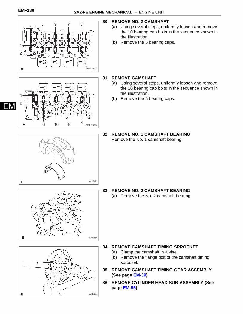
EM–130 2AZ-FE ENGINE MECHANICAL – ENGINE UNIT
EM
30. REMOVE NO. 2 CAMSHAFT(a) Using several steps, uniformly loosen and remove
the 10 bearing cap bolts in the sequence shown in the illustration.
(b) Remove the 5 bearing caps.
31. REMOVE CAMSHAFT(a) Using several steps, uniformly loosen and remove
the 10 bearing cap bolts in the sequence shown in the illustration.
(b) Remove the 5 bearing caps.
32. REMOVE NO. 1 CAMSHAFT BEARINGRemove the No. 1 camshaft bearing.
33. REMOVE NO. 2 CAMSHAFT BEARING(a) Remove the No. 2 camshaft bearing.
34. REMOVE CAMSHAFT TIMING SPROCKET(a) Clamp the camshaft in a vise.(b) Remove the flange bolt of the camshaft timing
sprocket.
35. REMOVE CAMSHAFT TIMING GEAR ASSEMBLY (See page EM-39)
36. REMOVE CYLINDER HEAD SUB-ASSEMBLY (See page EM-55)
1
5
6 810 4
79 3
2
A098174E11
1
2
6
5 79 3
810 4A098175E04
A128191
A032664
A032167

2AZ-FE ENGINE MECHANICAL – ENGINE UNIT EM–131
M
E37. REMOVE CYLINDER HEAD GASKET (See page EM-55)
38. REMOVE CYLINDER BLOCK WATER JACKET SPACER(a) Using needle-nose pliers, remove the cylinder block
water jacket spacer.NOTICE:Be sure to remove the water jacket spacer if turning the cylinder block upside down.
39. REMOVE CYLINDER BLOCK WATER DRAIN COCK SUB-ASSEMBLY (w/o Oil Cooler)(a) Remove the water drain cock from the stiffening
crankcase.(b) Remove the water drain cock plug from the water
drain cocks.
40. REMOVE OIL CONTROL VALVE FILTER(a) Using an 8 mm socket hexagon wrench, remove the
plug and filter.
41. REMOVE NO. 1 TAPER SCREW PLUG (w/o Oil Cooler)(a) Remove the taper screw plug.
A128208
A128209
A128210
A128211

EM–132 2AZ-FE ENGINE MECHANICAL – ENGINE UNIT
EM
42. REMOVE OIL PUMP ASSEMBLY(a) Remove the 3 bolts, oil pump and gasket.
43. REMOVE NO. 1 AND NO. 2 BALANCESHAFT SUB-ASSEMBLY(a) Uniformly loosen and remove the 8 bolts in the
sequence shown in the illustration.
(b) Remove the No. 1 and No. 2 balanceshafts.
44. REMOVE NO. 1 BALANCESHAFT BEARING(a) Remove the balanceshaft bearings.
A128253
4
8
6
2
1
5
7
3A128197E01
No. 1 Balanceshaft
No. 2 BalanceshaftA128203E02
Stiffening Crankcase:
Balanceshaft Housing:
A128204E02

2AZ-FE ENGINE MECHANICAL – ENGINE UNIT EM–133
M
E45. REMOVE ENGINE REAR OIL SEAL(a) Using a knife, cut off the oil seal lip.(b) Using a screwdriver with its tip taped, pry out the oil
seal.NOTICE:After removing the oil seal, check the crankshaft for damage. If it is damaged, smooth the surface with 400-grit sandpaper.
46. REMOVE STIFFENING CRANKCASE ASSEMBLY(a) Uniformly loosen and remove the 11 bolts in the
sequence shown in the illustration.
(b) Using a screwdriver, remove the crankcase by prying between the crankcase and cylinder block.NOTICE:Be careful not to damage the contact surfaces of the crankcase and cylinder block.
(c) Remove the O-ring from the cylinder block.
Cut Position
A128201E01
1
2 3
4
5
6 7
89
10
11
A128202E02
Protective Tape
Protective TapeA128205E01
A128206

EM–134 2AZ-FE ENGINE MECHANICAL – ENGINE UNIT
EM
47. REMOVE PISTON SUB-ASSEMBLY WITH CONNECTING ROD(a) Using a ridge reamer, remove all the carbon from
the top of the cylinder.
(b) Check that the matchmarks on the connecting rod and cap are aligned to ensure the correct reassembly.HINT:The matchmarks on the connecting rods and caps are provided for ensuring the correct reassembly.
(c) Using a 12 mm socket wrench, uniformly loosen the 2 bolts.
(d) Using the 2 removed connecting rod cap bolts, remove the connecting rod cap and lower bearing by wiggling the connecting rod cap right and left.HINT:Keep the lower bearing inserted in the connecting rod cap.
(e) Push the piston, connecting rod assembly and upper bearing through the top of the cylinder block.HINT:• Keep the bearing, connecting rod and cap
together.• Arrange the piston and connecting rod
assemblies in the correct order.
48. REMOVE CONNECTING ROD BEARING(a) Remove the connecting rod bearings.
HINT:Arrange the removed parts in the correct order.
49. REMOVE PISTON RING SET(a) Using a piston ring expander, remove the 2
compression rings.(b) Remove the oil ring rail and oil ring expander by
hand.HINT:Arrange the removed parts in the correct order.
A013469
Matchmark
A063893E01
A013397
Piston Ring Expander
A128232E01

2AZ-FE ENGINE MECHANICAL – ENGINE UNIT EM–135
M
E50. REMOVE PISTON PIN HOLE SNAP RING(a) Using a screwdriver, pry out the 2 snap rings.
51. REMOVE PISTON(a) Gradually heat the piston to approximately 80 to
90°C (176 to 194°F).
(b) Using a plastic hammer and brass bar, lightly tap out the piston pin and remove the connecting rod.HINT:• The piston and pin are a matched set.• Arrange the pistons, pins, rings, connecting rods
and bearings in the correct order.
52. REMOVE CRANKSHAFT(a) Uniformly loosen and remove the 10 main bearing
cap bolts in the sequence shown in the illustration.
(b) Use 2 removed main bearing cap bolts to remove the 5 main bearing caps and 5 lower bearings.NOTICE:Insert the bolts into one of the caps. Ease the cap out by gently pulling up and applying force toward the front and back side of the cylinder block, as shown in the illustration. Take care not to damage the contact surfaces of the cap and cylinder block.
A128233
A109729
A106279
1
2
3
4
5
6
7
8
9
10
A128235E01
A087781

EM–136 2AZ-FE ENGINE MECHANICAL – ENGINE UNIT
EM
HINT:• Keep the lower bearing and main bearing cap
together.• Arrange the main bearing caps in the correct
order.(c) Lift out the crankshaft.
53. REMOVE UPPER CRANKSHAFT THRUST WASHER(a) Remove the upper thrust washers from the cylinder
block.
54. REMOVE CRANKSHAFT BEARING(a) Remove the 5 upper main bearings from the
cylinder block.HINT:Arrange the bearings in the correct order.
55. REMOVE NO. 2 CRANKSHAFT BEARING(a) Remove the 5 lower main bearings from the 5 main
bearing caps.HINT:Arrange the bearings in the correct order.
56. REMOVE STUD BOLT
57. REMOVE NO. 1 OIL NOZZLE SUB-ASSEMBLY(a) Using a 5 mm hexagon wrench, remove the bolts
and oil nozzles.
58. CLEAN CYLINDER BLOCKNOTICE:If the cylinder is washed at high temperatures, the cylinder liner will stick out beyond the cylinder block. Always wash the cylinder block at a temperature of 45°C (113°F) or less.
A013501
A063901
A063902
A128251E01

2AZ-FE ENGINE MECHANICAL – ENGINE UNIT EM–137
M
EINSPECTION1. INSPECT BALANCESHAFT THRUST CLEARANCE
(a) Install the balanceshafts (See page EM-149). (b) Using a dial indicator, measure the thrust clearance
while moving the balanceshaft back and forth.Standard thrust clearance:
0.05 to 0.09 mm (0.0020 to 0.0035 in.)Maximum thrust clearance:
0.09 mm (0.0035 in.)If the thrust clearance is greater than the maximum, replace the balanceshaft housing and bearings. If necessary, replace the balanceshaft.
2. INSPECT BALANCESHAFT OIL CLEARANCE(a) Clean each bearing and journal.(b) Check each bearing and journal for pitting and
scratches.If a bearing or journal is damaged, replace the bearings. If necessary, replace the balanceshaft.
(c) Place the No. 1 and No. 2 balanceshafts onto the crankcase.
(d) Lay a strip of Plastigage across each journal.(e) Install the balanceshaft housing (See page EM-
149).NOTICE:Do not turn the balanceshafts.
(f) Remove the balanceshafts (See page EM-127).
(g) Measure the Plastigage at its widest point.Standard oil clearance:
0.004 to 0.049 mm (0.0002 to 0.0019 in.)Maximum oil clearance:
0.049 mm (0.0019 in.)NOTICE:Remove the Plastigage completely after the measurement.If the oil clearance is greater than the maximum, replace the bearing. If necessary, replace the balanceshaft.
(h) If replacing a bearing, select a new one with the same number.Standard balanceshaft housing journal bore diameter
A128196
Plastigage
A128198E01
Plastigage
A128199E01
Item Specified Condition
Mark 1 26.000 to 26.006 mm (1.0236 to 1.0239 in.)
Mark 2 26.007 to 26.012 mm (1.0239 to 1.0241 in.)
Mark 3 26.013 to 26.018 mm (1.0241 to 1.0243 in.)

EM–138 2AZ-FE ENGINE MECHANICAL – ENGINE UNIT
EM
Standard bearing center wall thickness
Standard balanceshaft journal diameter
(i) Inspect the balanceshaft housing bolts.(1) Using vernier calipers, measure the length of
the bolts from the seat to the end.Standard bolt length:
58.3 to 59.7 mm (2.295 to 2.350 in.)Maximum bolt length:
60.3 mm (2.374 in.)If the bolt length is greater than the maximum, replace the balanceshaft housing bolt.
3. INSPECT CHAIN SUB-ASSEMBLY(a) Pull the chain with a force of 140 N (14.3 kgf, 31.5
lbf) as shown in the illustration.(b) Using vernier calipers, measure the length of 15
links.Maximum chain elongation:
114.5 mm (4.508 in.)NOTICE:Perform the measurement at 3 random places. Use the average of the measurements.If the elongation is greater than the maximum, replace the chain.
4. INSPECT NO. 2 CHAIN SUB-ASSEMBLY(a) Pull the chain with a force of 140 N (14.3 kgf, 31.5
lbf) as shown in the illustration.(b) Using vernier calipers, measure the length of 15
links.Maximum chain elongation:
102.2 mm (4.024 in.)NOTICE:Perform the measurement at 3 random places. Use the average of the measurements.If the elongation is greater than the maximum, replace the No. 2 chain.
Item Specified Condition
Mark 1 1.486 to 1.489 mm (0.05850 to 0.05862 in.)
Mark 2 1.490 to 1.492 mm (0.05866 to 0.05874 in.)
Mark 3 1.493 to 1.495 mm (0.0588 to 0.0589 in.)
Item Journal diameter
Mark 1 22.985 to 23.000 mm (0.9049 to 0.9055 in.)
Mark 2 22.985 to 23.000 mm (0.9049 to 0.9055 in.)
Mark 3 22.985 to 23.000 mm (0.9049 to 0.9055 in.)
Length
A131575E01
Measuring Area
1 2 3 4 5 6 15A135727E01
Measuring Area
1 2 3 4 5 6 15A135727E01

2AZ-FE ENGINE MECHANICAL – ENGINE UNIT EM–139
M
E5. INSPECT OIL PUMP DRIVE GEAR(a) Wrap the chain around the sprocket.(b) Using vernier calipers, measure the sprocket
diameter with the chain wrapped around.Minimum gear diameter (with chain):
48.2 mm (1.898 in.)NOTICE:The vernier calipers must be in contact with the chain rollers when measuring.If the diameter is less than the minimum, replace the chain and sprocket.
6. INSPECT OIL PUMP DRIVE SHAFT GEAR(a) Wrap the chain around the sprocket.(b) Using vernier calipers, measure the sprocket
diameter with the chain wrapped around.Minimum gear diameter (with chain):
48.2 mm (1.898 in.)NOTICE:The vernier calipers must be in contact with the chain rollers when measuring.If the diameter is less than the minimum, replace the chain and sprocket.
7. INSPECT CAMSHAFT TIMING GEAR ASSEMBLY(a) Wrap the chain around the sprocket.(b) Using vernier calipers, measure the sprocket
diameter with the chain wrapped around.Minimum gear diameter (with chain):
97.3 mm (3.831 in.)NOTICE:The vernier calipers must be in contact with the chain rollers when measuring.If the diameter is less than the minimum, replace the chain and sprocket.
8. INSPECT CAMSHAFT TIMING SPROCKET(a) Wrap the chain around the sprocket.(b) Using vernier calipers, measure the sprocket
diameter with the chain wrapped around.Minimum gear diameter (with chain):
97.3 mm (3.831 in.)NOTICE:The vernier calipers must be in contact with the chain rollers when measuring.If the diameter is less than the minimum, replace the chain and sprocket.
A053035E01
A053036E01
A063864
A053025
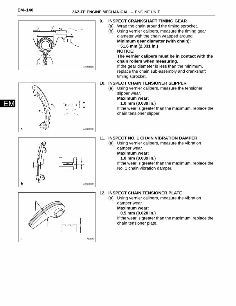
EM–140 2AZ-FE ENGINE MECHANICAL – ENGINE UNIT
EM
9. INSPECT CRANKSHAFT TIMING GEAR(a) Wrap the chain around the timing sprocket.(b) Using vernier calipers, measure the timing gear
diameter with the chain wrapped around.Minimum gear diameter (with chain):
51.6 mm (2.031 in.)NOTICE:The vernier calipers must be in contact with the chain rollers when measuring.If the gear diameter is less than the minimum, replace the chain sub-assembly and crankshaft timing sprocket.
10. INSPECT CHAIN TENSIONER SLIPPER(a) Using vernier calipers, measure the tensioner
slipper wear.Maximum wear:
1.0 mm (0.039 in.)If the wear is greater than the maximum, replace the chain tensioner slipper.
11. INSPECT NO. 1 CHAIN VIBRATION DAMPER(a) Using vernier calipers, measure the vibration
damper wear.Maximum wear:
1.0 mm (0.039 in.)If the wear is greater than the maximum, replace the No. 1 chain vibration damper.
12. INSPECT CHAIN TENSIONER PLATE(a) Using vernier calipers, measure the vibration
damper wear.Maximum wear:
0.5 mm (0.020 in.)If the wear is greater than the maximum, replace the chain tensioner plate.
A053035E01
A033838E01
A036686E01
A126893

2AZ-FE ENGINE MECHANICAL – ENGINE UNIT EM–141
M
E13. INSPECT NO. 1 CHAIN TENSIONER(a) Check that the plunger moves smoothly when the
ratchet pawl is raised with your finger.(b) Release the ratchet pawl, then check that the
plunger is locked in place by the ratchet pawl and does not move when pushed with your finger.
14. INSPECT CONNECTING ROD THRUST CLEARANCE(a) Install the connecting rod cap (See page EM-149).
(b) Using a dial indicator, measure the thrust clearance while moving the connecting rod back and forth.Standard thrust clearance:
0.160 to 0.362 mm (0.0063 to 0.0143 in.)Maximum thrust clearance:
0.362 mm (0.0143 in.)If the thrust clearance is greater than the maximum, replace the connecting rod assemblies as necessary. If necessary, replace the crankshaft.
15. INSPECT CONNECTING ROD OIL CLEARANCE(a) Clean the crank pin and bearing.(b) Check the crank pin and bearing for pitting and
scratches.(c) Lay a strip of Plastigage on the crank pin.
(d) Check that the front mark of the connecting rod cap is facing forward.
(e) Install the connecting rod cap (See page EM-149).NOTICE:Do not turn the crankshaft.
(f) Remove the 2 bolts and connecting rod cap (See page EM-127).
Lock
Move
Raise
A098357E01
A036642
Plastigage
A013400E01
Front Mark
A036691E01

EM–142 2AZ-FE ENGINE MECHANICAL – ENGINE UNIT
EM
(g) Measure the Plastigage at its widest point.Standard oil clearance:
0.032 to 0.063 mm (0.0013 to 0.0025 in.)Maximum oil clearance:
0.063 mm (0.0025 in.)NOTICE:Completely remove the Plastigage after the measurement.If the oil clearance is greater than the maximum, replace the connecting rod bearings. If necessary, inspect the crankshaft.HINT:If replacing a bearing, replace it with one that has the same number as its respective connecting rod cap. Each bearing's standard thickness is indicated by a 1, 2, or 3 mark on its surface.Standard connecting rod large end bore diameter
Standard connecting rod bearing thickness
Standard crankshaft pin diameter
Plastigage
1, 2 or 3 Mark
A129453E03
Mark Specified Condition
Mark 1 51.000 to 51.007 mm (2.0079 to 2.0082 in.)
Mark 2 51.008 to 51.013 mm (2.0082 to 2.0084 in.)
Mark 3 51.014 to 51.020 mm (2.0084 to 2.0087 in.)
Mark Specified Condition
Mark 1 1.485 to 1.488 mm (0.0585 to 0.0586 in.)
Mark 2 1.489 to 1.491 mm (0.0586 to 0.0587 in.)
Mark 3 1.492 to 1.494 mm (0.0587 to 0.0588 in.)
Mark Specified Condition
Mark 1 47.990 to 48.000 (1.8894 to 1.8898 in.)
Mark 2 47.990 to 48.000 (1.8894 to 1.8898 in.)
Mark 3 47.990 to 48.000 (1.8894 to 1.8898 in.)
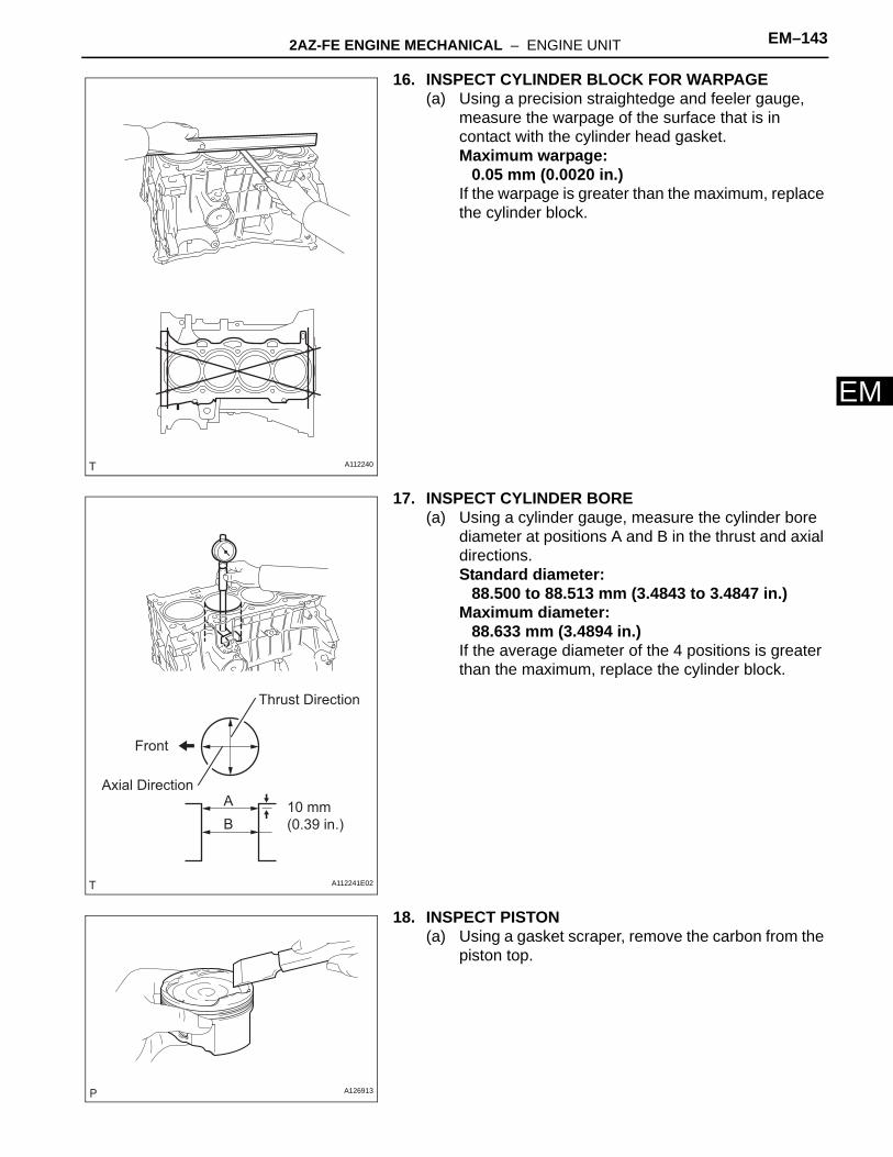
2AZ-FE ENGINE MECHANICAL – ENGINE UNIT EM–143
M
E16. INSPECT CYLINDER BLOCK FOR WARPAGE(a) Using a precision straightedge and feeler gauge,
measure the warpage of the surface that is in contact with the cylinder head gasket.Maximum warpage:
0.05 mm (0.0020 in.)If the warpage is greater than the maximum, replace the cylinder block.
17. INSPECT CYLINDER BORE(a) Using a cylinder gauge, measure the cylinder bore
diameter at positions A and B in the thrust and axial directions.Standard diameter:
88.500 to 88.513 mm (3.4843 to 3.4847 in.)Maximum diameter:
88.633 mm (3.4894 in.)If the average diameter of the 4 positions is greater than the maximum, replace the cylinder block.
18. INSPECT PISTON(a) Using a gasket scraper, remove the carbon from the
piston top.
A112240
Thrust Direction
Axial Direction10 mm (0.39 in.)
AB
Front
A112241E02
A126913

EM–144 2AZ-FE ENGINE MECHANICAL – ENGINE UNIT
EM
(b) Using a groove cleaning tool or a broken ring, clean the piston ring grooves.
(c) Using a brush and solvent, thoroughly clean the piston.NOTICE:Do not use a wire brush.
(d) Using a micrometer, measure the piston diameter at right angles to the piston pin hole, and at the piston 44.3 mm (1.7441 in.) from the piston head.Standard piston diameter:
88.469 to 88.479 mm (3.4830 to 3.4834 in.)If the diameter is not as specified, replace the piston.
19. INSPECT PISTON OIL CLEARANCE(a) Subtract the piston diameter measurement from the
cylinder bore diameter measurement.Standard oil clearance:
0.021 to 0.044 mm (0.0008 to 0.0017 in.)Maximum oil clearance:
0.10 mm (0.0039 in.)If the oil clearance is greater than the maximum, replace all the pistons. If necessary, replace the cylinder block.
20. INSPECT RING GROOVE CLEARANCE(a) Using a feeler gauge, measure the clearance
between a new piston ring and wall of the ring groove.Standard ring groove clearance
A126914
A126915
TMC Made:
TMMK Made:
44.3 mm (1.7441 in.)
44.3 mm (1.7441 in.)
A136099E01
A126911
Item Specified Condition
No. 1 Ring 0.020 to 0.070 mm (0.0008 to 0.0028 in.)
No. 2 Ring 0.020 to 0.060 mm (0.0008 to 0.0024 in.)
Oil Ring 0.020 to 0.070 mm (0.0008 to 0.0028 in.)
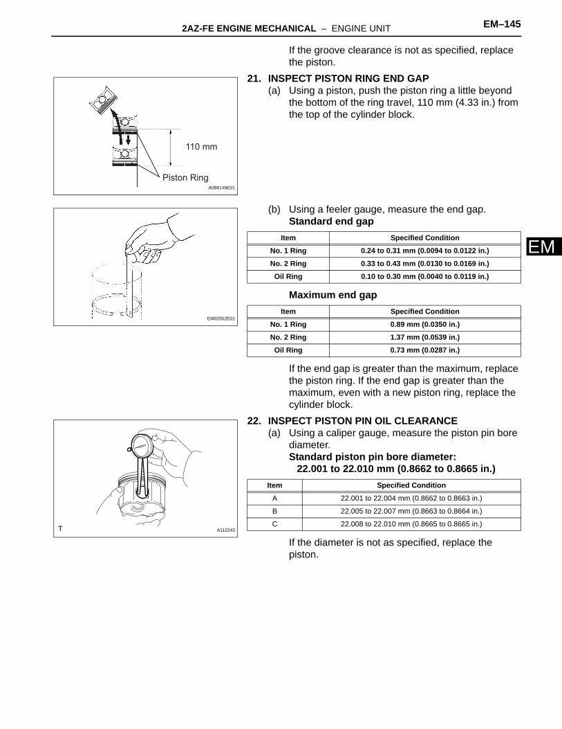
2AZ-FE ENGINE MECHANICAL – ENGINE UNIT EM–145
M
EIf the groove clearance is not as specified, replace the piston.
21. INSPECT PISTON RING END GAP(a) Using a piston, push the piston ring a little beyond
the bottom of the ring travel, 110 mm (4.33 in.) from the top of the cylinder block.
(b) Using a feeler gauge, measure the end gap.Standard end gap
Maximum end gap
If the end gap is greater than the maximum, replace the piston ring. If the end gap is greater than the maximum, even with a new piston ring, replace the cylinder block.
22. INSPECT PISTON PIN OIL CLEARANCE(a) Using a caliper gauge, measure the piston pin bore
diameter.Standard piston pin bore diameter:
22.001 to 22.010 mm (0.8662 to 0.8665 in.)
If the diameter is not as specified, replace the piston.
110 mm
Piston RingA098149E01
EM02552E01
Item Specified Condition
No. 1 Ring 0.24 to 0.31 mm (0.0094 to 0.0122 in.)
No. 2 Ring 0.33 to 0.43 mm (0.0130 to 0.0169 in.)
Oil Ring 0.10 to 0.30 mm (0.0040 to 0.0119 in.)
Item Specified Condition
No. 1 Ring 0.89 mm (0.0350 in.)
No. 2 Ring 1.37 mm (0.0539 in.)
Oil Ring 0.73 mm (0.0287 in.)
A112243
Item Specified Condition
A 22.001 to 22.004 mm (0.8662 to 0.8663 in.)
B 22.005 to 22.007 mm (0.8663 to 0.8664 in.)
C 22.008 to 22.010 mm (0.8665 to 0.8665 in.)

EM–146 2AZ-FE ENGINE MECHANICAL – ENGINE UNIT
EM
(b) Using a micrometer, measure the piston pin diameter.Standard piston pin diameter:
21.997 to 22.006 mm (0.8660 to 0.8664 in.)
If the diameter is not as specified, replace the piston pin.
(c) Using a caliper gauge, measure the connecting rod small end bore diameter.Standard connecting rod small end bore diameter:
22.005 to 22.014 mm (0.8663 to 0.8667 in.)
If the diameter is not as specified, replace the connecting rod.
(d) Subtract the piston pin diameter measurement from the piston pin bore diameter measurement.Standard oil clearance:
0.001 to 0.007 mm (0.00004 to 0.0003 in.)Maximum oil clearance:
0.010 mm (0.0004 in.)If the oil clearance is greater than the maximum, replace the connecting rod. If necessary, replace the piston and piston pin as a set.
(e) Subtract the piston pin diameter measurement from the connecting rod small end bore diameter measurement.Standard oil clearance:
0.005 to 0.011 mm (0.0002 to 0.0004 in.)Maximum oil clearance:
0.011 mm (0.0004 in.)If the oil clearance is greater than the maximum, replace the connecting rod. If necessary, replace the connecting rod and piston pin as a set.
5 mm (0.20 in.)
30 mm (1.18 in.)
5 mm (0.20 in.) A120741E02
Item Specified Condition
A 21.997 to 22.000 mm (0.8660 to 0.8661 in.)
B 22.001 to 22.003 mm (0.8662 to 0.8663 in.)
C 22.004 to 22.006 mm (0.8663 to 0.8664 in.)
A001185E01
Item Specified Condition
A 22.005 to 22.008 mm (0.8663 to 0.8665 in.)
B 22.009 to 22.011 mm (0.8665 to 0.8666 in.)
C 22.012 to 22.014 mm (0.8666 to 0.8667 in.)
Piston Pin Bore Diameter Mark
Front Mark
Front Mark
Connecting Rod Small End Bore Diameter Mark
TMC Made:TMMK Made:
A136100E01

2AZ-FE ENGINE MECHANICAL – ENGINE UNIT EM–147
M
E23. INSPECT CONNECTING ROD BOLT(a) Using vernier calipers, measure the tension portion
diameter of the bolt.Standard diameter:
7.2 to 7.3 mm (0.283 to 0.287 in.)Minimum diameter:
7.0 mm (0.276 in.)If the diameter is less than the minimum, replace the connecting rod bolt.
24. INSPECT CONNECTING ROD SUB-ASSEMBLY(a) Using a connecting rod aligner and feeler gauge,
check the connecting rod alignment.(1) Check for misalignment.
Maximum misalignment:0.05 mm (0.0020 in.) per 100 mm (3.94 in.)
If the misalignment is greater than the maximum, replace the connecting rod.
(2) Check for twist.Maximum twist:
0.15 mm (0.0059 in.) per 100 mm (3.94 in.)If the twist is greater than the maximum, replace the connecting rod.
25. INSPECT CRANKSHAFT(a) Using a dial indicator and V-blocks, measure the
circle runout as shown in the illustration.Maximum circle runout:
0.03 mm (0.0012 in.)If the taper and distortion are greater than the maximum, replace the crankshaft.
A036651
Z000064E03
Z000065E02
A013491E01

EM–148 2AZ-FE ENGINE MECHANICAL – ENGINE UNIT
EM
(b) Using a micrometer, measure the diameter of each main journal.Standard diameter:
54.988 to 55.000 mm (2.1649 to 2.1654 in.)If the diameter is not as specified, check the crankshaft oil clearance.
(c) Check each main journal for taper and distortion as shown in the illustration.Maximum taper and distortion:
0.003 mm (0.0001 in.)If the taper and distortion are greater than the maximum, replace the crankshaft.Standard diameter (Reference)
(d) Using a micrometer, measure the diameter of each crank pin.Standard diameter:
47.990 to 48.000 mm (1.8894 to 1.8898 in.)If the diameter is not as specified, check the connecting rod oil clearance.
(e) Inspect each crank pin for taper and distortion as shown in the illustration.Maximum taper and distortion:
0.003 mm (0.0001 in.)If the taper and distortion are greater than the maximum, replace the crankshaft.
26. INSPECT CRANKSHAFT THRUST CLEARANCE(a) Install the main bearing cap (See page EM-149). (b) Using a dial indicator, measure the thrust clearance
while prying the crankshaft back and forth with a screwdriver.Standard thrust clearance:
0.04 to 0.24 mm (0.0016 to 0.0095 in.)Maximum thrust clearance:
0.30 mm (0.0118 in.)If the thrust clearance is greater than the maximum, replace the thrust washers as a set.HINT:The thrust washer thickness is 1.93 to 1.98 mm (0.0760 to 0.0780 in.).
27. INSPECT CRANKSHAFT OIL CLEARANCE(a) Check the crank journal and bearing for pitting and
scratches.(b) Install the crankshaft bearing (See page EM-149). (c) Place the crankshaft on the cylinder block.
No. 1
No. 3
No. 5No. 4
No. 2
A098151E01
Mark Specified Condition
0 54.999 to 55.000 mm (2.1653 to 2.1654 in.)
1 54.997 to 54.998 mm (2.1652 to 2.1653 in.)
2 54.995 to 54.996 mm (2.1652 to 2.1652 in.)
3 54.993 to 54.994 mm (2.1651 to 2.1651 in.)
4 54.991 to 54.992 mm (2.1650 to 2.1650 in.)
5 54.988 to 54.990 mm (2.1649 to 2.1650 in.)
ZF06928E02
A128234
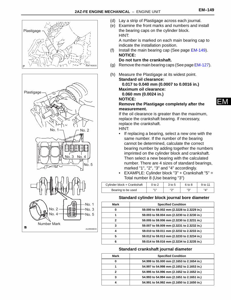
2AZ-FE ENGINE MECHANICAL – ENGINE UNIT EM–149
M
E(d) Lay a strip of Plastigage across each journal.(e) Examine the front marks and numbers and install
the bearing caps on the cylinder block.HINT:A number is marked on each main bearing cap to indicate the installation position.
(f) Install the main bearing cap (See page EM-149). NOTICE:Do not turn the crankshaft.
(g) Remove the main bearing caps (See page EM-127).
(h) Measure the Plastigage at its widest point.Standard oil clearance:
0.017 to 0.040 mm (0.0007 to 0.0016 in.)Maximum oil clearance:
0.060 mm (0.0024 in.)NOTICE:Remove the Plastigage completely after the measurement.If the oil clearance is greater than the maximum, replace the crankshaft bearing. If necessary, replace the crankshaft.HINT:• If replacing a bearing, select a new one with the
same number. If the number of the bearing cannot be determined, calculate the correct bearing number by adding together the numbers imprinted on the cylinder block and crankshaft. Then select a new bearing with the calculated number. There are 4 sizes of standard bearings, marked "1", "2", "3" and "4" accordingly.
• EXAMPLE: Cylinder block "3" + Crankshaft "5" = Total number 8 (Use bearing "3")
Standard cylinder block journal bore diameter
Standard crankshaft journal diameter
Plastigage
A087782E03
No. 1 No. 2
No. 3
No. 5
No. 4
No. 1No. 2 No. 3
No. 5No. 4
Plastigage
Number MarkA129506E03
Cylinder block + Crankshaft 0 to 2 3 to 5 6 to 8 9 to 11
Bearing to be used "1" "2" "3" "4"
Mark Specified Condition
0 59.000 to 59.002 mm (2.3228 to 2.3229 in.)
1 59.003 to 59.004 mm (2.3230 to 2.3230 in.)
2 59.005 to 59.006 mm (2.3230 to 2.3231 in.)
3 59.007 to 59.009 mm (2.3231 to 2.3232 in.)
4 59.010 to 59.011 mm (2.3232 to 2.3233 in.)
5 59.012 to 59.013 mm (2.3233 to 2.3234 in.)
6 59.014 to 59.016 mm (2.3234 to 2.3235 in.)
Mark Specified Condition
0 54.999 to 55.000 mm (2.1653 to 2.1654 in.)
1 54.997 to 54.998 mm (2.1652 to 2.1653 in.)
2 54.995 to 54.996 mm (2.1652 to 2.1652 in.)
3 54.993 to 54.994 mm (2.1651 to 2.1651 in.)
4 54.991 to 54.992 mm (2.1650 to 2.1650 in.)

EM–150 2AZ-FE ENGINE MECHANICAL – ENGINE UNIT
EM
Standard bearing center wall thickness
28. INSPECT CRANKSHAFT BEARING CAP SET BOLT(a) Using vernier calipers, measure the tension portion
diameter of the bolts.Standard diameter:
7.3 to 7.5 mm (0.287 to 0.295 in.)Minimum diameter:
7.2 mm (0.284 in.)If the diameter is less than the minimum, replace the bolt.
5 54.988 to 54.990 mm (2.1649 to 2.1650 in.)
Mark Specified Condition
1 1.993 to 1.996 mm (0.0785 to 0.0786 in.)
2 1.997 to 1.999 mm (0.0786 to 0.0787 in.)
3 2.000 to 2.002 mm (0.0787 to 0.0788 in.)
4 2.003 to 2.005 mm (0.0789 to 0.0789 in.)
Mark Specified Condition
A064458

2AZ-FE ENGINE MECHANICAL – ENGINE UNIT EM–151
M
EREASSEMBLY1. INSTALL RING PIN
(a) Using a plastic hammer, tap into the ring pin.
Standard protrusion
Upper Side: Lower Side:
A
B
B
A
14.0 (0.551) 13.0 (0.512)
12.0 (0.472) 12.0 (0.472)
Protrusion Height
mm (in.)A B
A112251E02
Item Protrusion
Pin A 6 mm (0.236 in.)
Pin B 5 mm (0.197 in.)

EM–152 2AZ-FE ENGINE MECHANICAL – ENGINE UNIT
EM
2. INSTALL STUD BOLT(a) Install the stud bolts as shown in the illustration.
Torque: Stud Bolt A5.0 N*m (51 kgf*cm, 44 in.*lbf)Stud Bolt B22 N*m (220 kgf*cm, 16 ft.*lbf)Stud Bolt C9.5 N*m (97 kgf*cm, 84 in.*lbf)Stud Bolt D5.0 N*m (51 kgf*cm, 44 in.*lbf)
Front Side:
LH Side:
RH Side:
B
B
B C DA
A
C
D
27.5 (1.083)
12.0 (0.472)
9.0 (0.354)
9.0 (0.354)
12.0 (0.472)
84.0 (3.307)16.0 (0.630)
20.0 (0.787)
52.5 (2.067)
15.0 (0.591)
10.0 (0.394)
33.3 (1.311)
mm (in.)
A112253E02

2AZ-FE ENGINE MECHANICAL – ENGINE UNIT EM–153
M
E3. INSTALL STRAIGHT PIN(a) Using a plastic hammer, tap into the straight pin.
Standard protrusion
4. INSTALL NO. 1 OIL NOZZLE SUB-ASSEMBLY(a) Using a 5 mm hexagon wrench, install the oil
nozzles with the bolts.Torque: 7.0 N*m (71 kgf*cm, 62 in.*lbf)
A
A
A
C
CD D
C
B
B
B
18.0 (0.709)
8.0 (0.315) 8.0 (0.315) 10.0 (0.394) 7.0 (0.276)
15.0 (0.591)22.0 (0.866)
14.0 (0.551)
Protrusion Heightmm (in.)
Front Side:
Rear Side: RH Side:
Lower Side:
A112252E02
Item Protrusion
Pin A 8 mm (0.315 in.)
Pin B 7.5 mm (0.295 in.)
Pin C 12 mm (0.472 in.)
Pin D 5 mm (0.197 in.)
A128251E01

EM–154 2AZ-FE ENGINE MECHANICAL – ENGINE UNIT
EM
5. INSTALL PISTON(a) Using a screwdriver, install a new snap ring at one
end of the piston pin hole.HINT:Make sure that the end gap of the snap ring is not aligned with the pin hole cutout portion of the piston.
(b) Gradually heat the piston to approximately 80 to 90°C (176 to 194°F).
(c) Align the front marks of the piston and connecting rod, and push in the piston with your thumb.
(d) Using a screwdriver, install a new snap ring on the other end of the piston pin hole.HINT:Make sure that the end gap of the snap ring is not aligned with the pin hole cutout portion of the piston.
(e) Check the fitting condition between the piston and piston pin by trying to move the piston back and forth on the piston pin.
6. INSTALL PISTON RING SET(a) Install the oil ring expander and oil ring rail by hand.
NOTICE:• Install the expander and oil ring so that their
ring ends are at opposite sides.• Securely install the expander to the inner
groove of the oil ring.
A128244
Front Mark
Front Mark
Front Mark
TMC Made:
TMMK Made:
A136101E01
A107551
Oil Ring
Oil Ring (Expander)
Oil Ring (Expander)
Oil RingA131712E01

2AZ-FE ENGINE MECHANICAL – ENGINE UNIT EM–155
M
E(b) Using a piston ring expander, install the 2 compression rings so that the paint marks are positioned as shown in the illustration.NOTICE:Install the compression ring No. 2 with the code mark (2N and 2A) facing upward.
(c) Position the piston rings so that the ring ends are as shown in the illustration.
7. INSTALL CRANKSHAFT BEARING(a) Install the upper bearing with an oil groove on the
cylinder block.NOTICE:Do not apply engine oil to the bearings and the contact surfaces.
Piston Ring Expander
Upward
No. 1
No. 2
Paint Mark
TMC Made: (2N)
TMMK Made: (2A)
Paint Mark
(TMC Made)
A128246E01
Front Mark
No. 1 and Oil Ring Rail
No. 2 and Oil Ring Expander
Front MarkNo. 1 and Oil Ring Rail
No. 2 and Oil Ring Expander
TMC Made:
TMMK Made:
A136102E01
A053015

EM–156 2AZ-FE ENGINE MECHANICAL – ENGINE UNIT
EM
8. INSTALL NO. 2 CRANKSHAFT BEARING(a) Install the lower bearing on the bearing cap.
NOTICE:Clean the backside of the bearing and the bearing surface of the connecting rod. The surface should be free of dust and oils.
9. INSTALL UPPER CRANKSHAFT THRUST WASHER(a) Install the 2 thrust washers under the No. 3 journal
of the cylinder block with the oil grooves facing outward.
(b) Apply engine oil to the crankshaft thrust washer.
10. INSTALL CRANKSHAFT(a) Apply engine oil to the upper bearing and install the
crankshaft on the cylinder block.(b) Apply engine oil to the lower bearing.
(c) Examine the front marks and install the bearing caps on the cylinder block.
(d) Apply a light coat of engine oil to the threads and under the bearing cap bolts.
(e) Install the crankshaft bearing cap bolts.NOTICE:The main bearing cap bolts are tightened in 2 progressive steps.
(f) Step 1(1) Install and uniformly tighten the 10 main
bearing cap bolts in the sequence shown in the illustration.Torque: 20 N*m (204 kgf*cm, 15 ft.*lbf)
(2) Retighten the 10 main bearing cap bolts in the sequence shown in the illustration.Torque: 40 N*m (408 kgf*cm, 30 ft.*lbf)
Claw
A063909E01
Oil Groove
A013501E01
Front Mark and NumberA128241E01
1
2
3
4
5
6
7
8
9
10
A128235E02
1
2
3
4
5
6
7
8
9
10
A128235E02
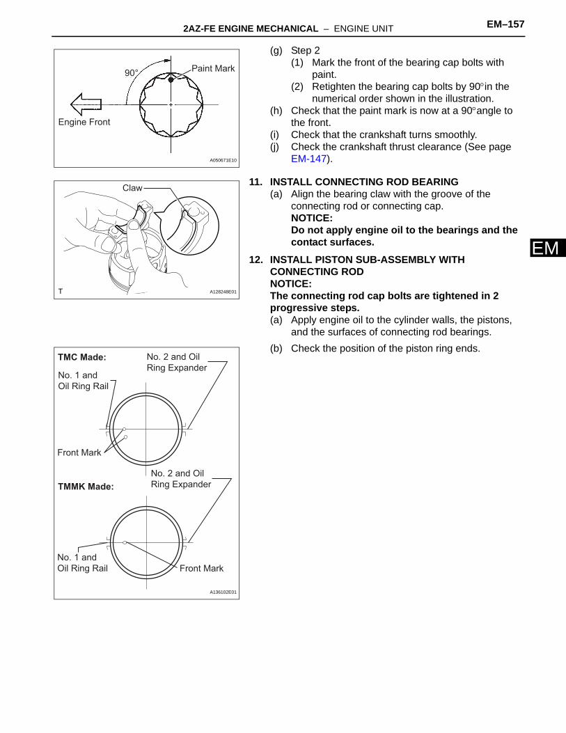
2AZ-FE ENGINE MECHANICAL – ENGINE UNIT EM–157
M
E(g) Step 2(1) Mark the front of the bearing cap bolts with
paint.(2) Retighten the bearing cap bolts by 90°in the
numerical order shown in the illustration.(h) Check that the paint mark is now at a 90°angle to
the front.(i) Check that the crankshaft turns smoothly.(j) Check the crankshaft thrust clearance (See page
EM-147).
11. INSTALL CONNECTING ROD BEARING(a) Align the bearing claw with the groove of the
connecting rod or connecting cap.NOTICE:Do not apply engine oil to the bearings and the contact surfaces.
12. INSTALL PISTON SUB-ASSEMBLY WITH CONNECTING RODNOTICE:The connecting rod cap bolts are tightened in 2 progressive steps.(a) Apply engine oil to the cylinder walls, the pistons,
and the surfaces of connecting rod bearings.(b) Check the position of the piston ring ends.
Engine Front
Paint Mark90°
A050671E10
Claw
A128248E01
Front Mark
No. 1 and Oil Ring Rail
No. 2 and Oil Ring Expander
Front MarkNo. 1 and Oil Ring Rail
No. 2 and Oil Ring Expander
TMC Made:
TMMK Made:
A136102E01

EM–158 2AZ-FE ENGINE MECHANICAL – ENGINE UNIT
EM
(c) Using a piston ring compressor, push the correctly numbered piston and connecting rod assemblies into each cylinder with the front mark of the piston facing forward.NOTICE:Match the numbered connecting rod cap with the connecting rod.
(d) Check that the protrusion of the connecting rod cap is facing in the correct direction.
(e) Apply a light coat of engine oil to the threads and under the heads of the connecting rod cap bolts.
(f) Install the connecting cap bolts.NOTICE:The connecting cap bolts should be tightened in 2 progressive steps.
(g) Step 1(1) Install and alternately tighten the bolts of the
connecting rod cap in several steps.Torque: 25 N*m (250 kgf*cm, 18 ft.*lbf)
(h) Step 2(1) Mark the front of the connecting rod cap bolts
with paint.(2) Retighten the cap bolts by 90°as shown in the
illustration.(i) Check that the crankshaft turns smoothly.(j) Check the connecting rod thrust clearance (See
page EM-140).
TMC Made: TMMK Made:
Front Mark
Front Front
Front Mark
A136103E01
Front Mark
A052515E01
A013397
90° Paint Mark
Engine Front
A101478E03

2AZ-FE ENGINE MECHANICAL – ENGINE UNIT EM–159
M
E13. INSTALL NO. 1 BALANCESHAFT BEARING(a) Install the bearings in the crankcase and
balanceshaft housing.NOTICE:Do not apply engine oil to the bearings and the contact surfaces.
(b) Apply a light coat of engine oil to the bearings.
14. INSTALL NO. 1 AND NO. 2 BALANCESHAFT SUB-ASSEMBLY(a) Rotate the driven gear No. 1 of balanceshaft No. 1
in the rotating direction until it hits the stopper.NOTICE:Confirm that the matchmarks on driven gears No. 1 and No. 2 are matched.
(b) Align the timing marks of the No. 1 and No. 2 balanceshafts as shown in the illustration.
(c) Place the No. 1 and No. 2 balanceshafts on the crankcase.
(d) Apply a light coat of engine oil under the heads of the balanceshaft housing bolts.
(e) Install the balanceshaft housing bolts.NOTICE:The balance shaft housing bolts are tightened in 2 progressive steps.
Stiffening Crankcase:
Balanceshaft Housing:
A128204E02
AlignRotating Direction
No. 1 Driven Gear
No. 2 Driven Gear
A128213E01
No. 1 Balanceshaft No. 2 Balanceshaft
Timing MarkA128214E02
No. 1 Balanceshaft
Timing Mark No. 2 BalanceshaftA131707E02

EM–160 2AZ-FE ENGINE MECHANICAL – ENGINE UNIT
EM
(f) Step 1(1) Install and uniformly tighten the 8 bolts in the
sequence shown in the illustration.Torque: 22 N*m (220 kgf*cm, 16 ft.*lbf)
(g) Step 2(1) Mark the front side of each balanceshaft
housing bolt head with paint.(2) Retighten the bolts by 90°as shown in the
illustration.(3) Check that the paint marks are now at a
90°angle to the front.
15. INSTALL STIFFENING CRANKCASE ASSEMBLY(a) Place a new O-ring on the cylinder block, as shown
in the illustration.(b) Temporarily tighten the pulley set bolt.
(c) Turn the crankshaft to set the crank pins of the No. 1 and No. 4 cylinders to the bottom.HINT:Make sure that the timing mark on the balanceshaft drive gear is positioned as shown in the illustration.
5
1
3
7
8
4
2
6A128197E04
90°
Engine Front
Paint MarkA037134E02
A128206
No. 1 and No. 4 Crank Pin
Drive GearApprox 16°
Front View:
Timing MarkA128255E01

2AZ-FE ENGINE MECHANICAL – ENGINE UNIT EM–161
M
E(d) Apply seal packing in a continuous bead (diameter: 2.5 to 3.0 mm (0.098 to 0.118 in.)) to the places shown in the illustration.Seal packing:
Toyota Genuine Seal Packing Black, Three bond 1207B or Equivalent
NOTICE:• Remove any oil from the contact surface.• Install the crankcase within 3 minutes after
applying seal packing.• Do not start the engine for at least 2 hours
after installing the crankcase stiffener.
(e) Install the stiffening crankcase so that the reference holes on the balanceshafts are positioned as shown in the illustration.
(f) Temporarily install the crankcase with the 11 bolts.Bolt length
A
B
C
D
2.5 to 3.0 mm (0.098 to 0.118 in.)
7.5 mm (0.295 in.)
7.5 mm (0.295 in.)
4.0 mm (0.158 in.)
A B C,D
A128254E01
Reference Hole
Timing Mark
A131254E01
A
B A
A
AA
B B
BBB
A128202E04
Item Length
Bolt A 122 mm (4.803 in.)
Bolt B 45 mm (1.772 in.)

EM–162 2AZ-FE ENGINE MECHANICAL – ENGINE UNIT
EM
(g) Uniformly tighten the 11 bolts in the sequence shown in the illustration.Torque: 24 N*m (245 kgf*cm, 18 ft.*lbf)
(h) Wipe off the excess seal packing with a clean piece of cloth.
(i) Turn the crankshaft again to set the key groove to the bottom. Make sure that the timing marks are aligned as shown in the illustration.HINT:An ' ' is stamped as a timing mark.
(j) Remove the pulley set bolt.
16. INSTALL OIL PUMP ASSEMBLY(a) Install a new gasket and oil pump with the 3 bolts.
Torque: 19 N*m (194 kgf*cm, 14 ft.*lbf)
17. INSTALL ENGINE REAR OIL SEAL(a) Using SST and a hammer, evenly tap the oil seal
until its surface is flush with the rear oil seal retainer edge.SST 09223-15030, 09950-70010 (09951-07100)NOTICE:Keep the lip free from foreign materials.
(b) Apply MP grease to a new oil seal lip.NOTICE:Wipe off extra grease on the crankshaft.
1
2
3 4
56
7
8
910
11
A128202E05
Key Groove
Approx. 5°
Timing Mark
Reference HoleApprox. 5°
A128215E01
A128253
SSTA128212E01

2AZ-FE ENGINE MECHANICAL – ENGINE UNIT EM–163
M
E18. INSTALL NO. 1 TAPER SCREW PLUG (w/o Oil Cooler)(a) Apply adhesive to 2 or 3 threads of the plug, and
install the plug.Torque: 26 N*m (265 kgf*cm, 19 ft.*lbf)Adhesive:
Toyota Genuine Adhesive 1324, Three Bond 1324 or Equivalent
19. INSTALL OIL CONTROL VALVE FILTER(a) Check that no foreign matter is on the mesh part of
the filter.(b) Using an 8 mm socket hexagon wrench, install a
new gasket and the oil control valve filter with the screw plug.Torque: 30 N*m (306 kgf*cm, 22 ft.*lbf)NOTICE:Do not touch the mesh when installing the oil control valve filter.
20. INSTALL CYLINDER BLOCK WATER DRAIN COCK SUB-ASSEMBLY (w/o Oil Cooler)(a) Apply adhesive around the drain cock.
Adhesive:Toyota Genuine Adhesive 1344, Three Bond 1344 or Equivalent
(b) Install the water drain cock within the range shown in the illustration.Torque: 25 N*m (255 kgf*cm, 18 ft.*lbf)NOTICE:Do not rotate the drain cocks more than 1 revolution (360°) after tightening the drain cocks to the specified torque.
(c) Install the water drain cock plugs to the water drain cocks.Torque: 13 N*m (130 kgf*cm, 9 ft.*lbf)
A128211
Oil Filter Control Valve
Gasket
PlugA128210E01
A135987
45° 45°A098363E01

EM–164 2AZ-FE ENGINE MECHANICAL – ENGINE UNIT
EM
21. INSTALL CYLINDER BLOCK WATER JACKET SPACER(a) Install the water jacket spacer as shown in the
illustration.HINT:Be sure to face the slope to the front of the engine.
22. INSTALL CYLINDER HEAD GASKET (See page EM-70)
23. INSTALL CYLINDER HEAD SUB-ASSEMBLY (See page EM-70)
24. INSTALL CAMSHAFT TIMING OIL CONTROL VALVE ASSEMBLY(a) Apply a light coat of engine oil to a new O-ring, then
install it onto the camshaft timing oil control valve.
(b) Install the camshaft timing oil control valve with the bolt.Torque: 9.0 N*m (92 kgf*cm, 80 in.*lbf)
25. INSTALL CAMSHAFT TIMING GEAR ASSEMBLY (See page EM-42)
26. INSTALL CAMSHAFT TIMING SPROCKET(a) Clamp the camshaft in a vise.(b) Tighten the flange bolt with the camshaft timing
sprocket fixed.Torque: 54 N*m (551 kgf*cm, 40 ft.*lbf)
27. INSTALL NO. 1 CAMSHAFT BEARING(a) Install the No. 1 camshaft bearing.
28. INSTALL NO. 2 CAMSHAFT BEARING (See page EM-71)
29. INSTALL CAMSHAFT(a) Apply a light coat of engine oil to the journal portion
of the camshaft.
Slope
A128252E01
O-Ring
A090053E02
A128171
A032167
A128191

2AZ-FE ENGINE MECHANICAL – ENGINE UNIT EM–165
M
E(b) Examine the front marks and numbers, and check that the order is as shown in the illustration. Then install the bearing caps into the cylinder head.
(c) Apply a light coat of engine oil to the threads and under the heads of the bearing cap bolts.
(d) Using several steps, uniformly tighten the 10 bearing cap bolts in the sequence shown in the illustration.Torque: No. 1 Bearing cap
30 N*m (301 kgf*cm, 22 ft.*lbf)No. 3 Bearing cap9.0 N*m (92 kgf*cm, 80 in.*lbf)
30. INSTALL NO. 2 CAMSHAFT(a) Apply a light coat of engine oil to the journal portion
of the No. 2 camshaft.
(b) Examine the front marks and numbers, and check that the order is as shown in the illustration. Then install the bearing caps onto the cylinder head.
(c) Apply a light coat of engine oil to the threads and under the heads of the bearing cap bolts.
(d) Using several steps, uniformly tighten the 10 bearing cap bolts in the sequence shown in the illustration.Torque: No. 1 Bearing cap
30 N*m (301 kgf*cm, 22 ft.*lbf)No. 3 Bearing cap9.0 N*m (92 kgf*cm, 80 in.*lbf)
31. INSTALL KEYS(a) Install the 2 keys.
32. INSTALL NO. 2 CHAIN SUB-ASSEMBLY (See page EM-27)
33. INSTALL CRANKSHAFT TIMING SPROCKET (See page EM-28)
34. INSTALL NO. 1 CHAIN VIBRATION DAMPER (See page EM-28)
35. INSTALL CHAIN SUB-ASSEMBLY (See page EM-28)
A098177E03
8
4 2 6 10
73 1 5 9
No. 1
A098177E06
A098174E05
7
3
4 2 6 10
1 5 9
8
No. 2A098174E07
A131498

EM–166 2AZ-FE ENGINE MECHANICAL – ENGINE UNIT
EM
36. INSTALL CHAIN TENSIONER SLIPPER (See page EM-29)
37. INSTALL TIMING CHAIN GUIDE (See page EM-30)38. INSTALL NO. 1 CRANKSHAFT POSITION SENSOR
PLATE (See page EM-30)39. INSTALL TIMING CHAIN CASE OIL SEAL
(a) Using SST, tap in a new oil seal until its surface is flush with the timing chain cover edge.SST 09223-22010
(b) Apply a light coat of MP grease to the lip of the oil seal.NOTICE:Keep the gap between the timing chain cover edge and the oil seal free of foreign matter.
40. INSTALL TIMING CHAIN COVER SUB-ASSEMBLY (See page LU-15)
41. INSTALL V-RIBBED BELT TENSIONER ASSEMBLY (See page EM-30)
42. INSTALL OIL PAN SUB-ASSEMBLY (See page EM-31)43. INSTALL OIL PAN DRAIN PLUG
(a) Install a new gasket and oil pan drain plug with a new gasket.Torque: 25 N*m (255 kgf*cm, 18 ft.*lbf)
44. INSTALL WATER PUMP ASSEMBLY (See page CO-10)
45. INSTALL WATER PUMP PULLEY (See page CO-11)
46. INSTALL CRANKSHAFT POSITION SENSOR(a) Apply a light coat of engine oil to the O-ring of the
sensor.
(b) Confirm that the wire harness of the sensor is placed as shown in the illustration.
SST
A128223E01
A128176
O-Ring
A095436E01
Wire Harness
RibClamp
A052071E05

2AZ-FE ENGINE MECHANICAL – ENGINE UNIT EM–167
M
E(c) Install the sensor with the 2 bolts.Torque: 9.0 N*m (92 kgf*cm, 80 in.*lbf)
(d) Install the clamp of the crankshaft position sensor onto the water pump.
47. INSTALL CRANKSHAFT PULLEY (See page EM-76)48. INSTALL NO. 1 CHAIN TENSIONER ASSEMBLY (See
page EM-32)49. INSPECT VALVE CLEARANCE (See page EM-8)50. ADJUST VALVE CLEARANCE (See page EM-9)
51. INSTALL CAMSHAFT POSITION SENSOR(a) Apply a light coat of engine oil to the O-ring of the
sensor.
(b) Install the sensor with the bolt.Torque: 9.0 N*m (92 kgf*cm, 80 in.*lbf)
52. INSTALL CYLINDER HEAD COVER GASKET(a) Install the gasket to the cylinder head cover.
NOTICE:Remove any oil from the contact surface.
53. INSTALL CYLINDER HEAD COVER SUB-ASSEMBLY (See page EM-33)
A063828
A094516E01
O-Ring
A095434E01
A128164
A128166
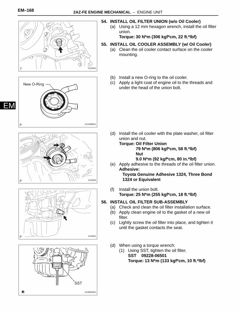
EM–168 2AZ-FE ENGINE MECHANICAL – ENGINE UNIT
EM
54. INSTALL OIL FILTER UNION (w/o Oil Cooler)(a) Using a 12 mm hexagon wrench, install the oil filter
union.Torque: 30 N*m (306 kgf*cm, 22 ft.*lbf)
55. INSTALL OIL COOLER ASSEMBLY (w/ Oil Cooler)(a) Clean the oil cooler contact surface on the cooler
mounting.
(b) Install a new O-ring to the oil cooler.(c) Apply a light coat of engine oil to the threads and
under the head of the union bolt.
(d) Install the oil cooler with the plate washer, oil filter union and nut.Torque: Oil Filter Union
79 N*m (806 kgf*cm, 58 ft.*lbf)Nut9.0 N*m (92 kgf*cm, 80 in.*lbf)
(e) Apply adhesive to the threads of the oil filter union.Adhesive:
Toyota Genuine Adhesive 1324, Three Bond 1324 or Equivalent
(f) Install the union bolt.Torque: 25 N*m (255 kgf*cm, 18 ft.*lbf)
56. INSTALL OIL FILTER SUB-ASSEMBLY(a) Check and clean the oil filter installation surface.(b) Apply clean engine oil to the gasket of a new oil
filter.(c) Lightly screw the oil filter into place, and tighten it
until the gasket contacts the seat.
(d) When using a torque wrench:(1) Using SST, tighten the oil filter.
SST 09228-06501Torque: 13 N*m (133 kgf*cm, 10 ft.*lbf)
A128162
New O-Ring
A124389E01
A135533
A129331
SST
A129850E01

2AZ-FE ENGINE MECHANICAL – ENGINE UNIT EM–169
M
E(e) When not using a torque wrench:(1) Using SST, tighten it an additional 3/4 turn.
SST 09228-06501
57. INSTALL SPARK PLUG(a) Install the spark plugs.
Torque: 19 N*m (194 kgf*cm, 14 ft.*lbf)
58. INSTALL VENTILATION VALVE SUB-ASSEMBLY(a) Apply adhesive to the threads of the ventilation
valve.
(b) Install the ventilation valve.Torque: 19 N*m (194 kgf*cm, 14 ft.*lbf)Adhesive:
Toyota Genuine Adhesive 1324, Three Bond 1324 or Equivalent
59. INSTALL OIL FILLER CAP GASKET(a) Install a new gasket to the cap.
SST
3/4 Turn
A129851E01
A128161
Adhesive
A092670E03
A128160
A128159

EM–170 2AZ-FE ENGINE MECHANICAL – ENGINE UNIT
EM
60. INSTALL OIL FILLER CAP SUB-ASSEMBLY(a) Install the oil filler cap.
A128158
Recommended