Explosion-Proof Devices 2015 / 2016
TPK Kapfer GmbHSchillerstraße 13D-74219 MöckmühlTel. ++49 (0) 62 98 / 70 62Fax ++49 (0) 62 98 / 70 61
TPK Kapfer GmbHSchillerstraße 13D-74219 MöckmühlTel. ++49 (0) 62 98 / 70 62Fax ++49 (0) 62 98 / 70 61
TP
K K
apfe
r G
mb
H
E
xplo
sio
n-P
roo
f D
evic
es 2
015
/ 201
6
Mini-LED
Typ mS73M-65 Page 5
Signal transmitter
Typ mS75M-83 Page 18
Mini-pushbutton
Typ dS77M-81 Page 17
Rotary switch
Typ dS79M-5616 D Page 21
Lighted mini-pushbutton
Typ mS71M-7916 Page 16
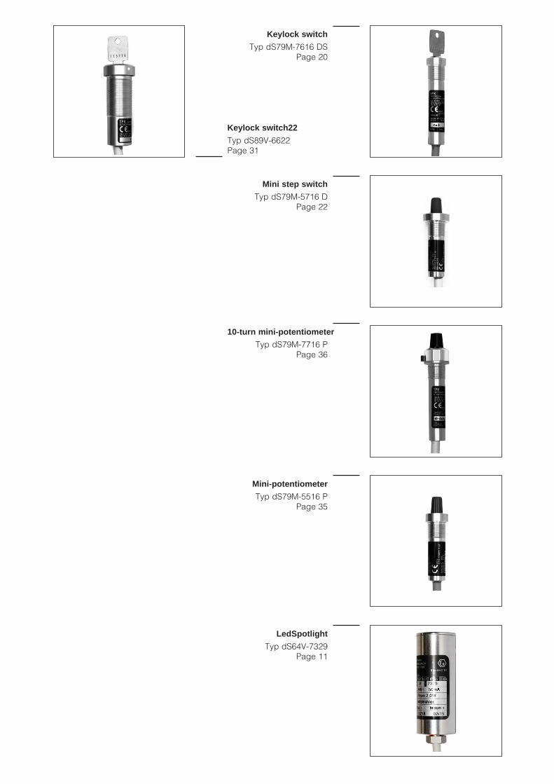
Mini step switch
Typ dS79M-5716 D Page 22
Keylock switch
Typ dS79M-7616 DS Page 20
10-turn mini-potentiometer
Typ dS79M-7716 P Page 36
Mini-potentiometer
Typ dS79M-5516 P Page 35
Led22
Typ dS83V-5322 Page 24
Pushbutton22
Typ dS87V-5322 Page 27
Rotary switch22
Typ dS89V-5322 Page 30
Lighted pushbutton22
Typ dS81V-8322 Page 26
Keylock switch22
Typ dS89V-6622 Page 31
LedSpotlight
Typ dS64V-7329 Page 11
Kapfer GmbHTel. ++49 (0) 62 98 / 70 62Fax ++49 (0) 62 98 / 70 61
3
Contents
You can view and download the test certificates on our website www.tpk-kapfer.de.
We look forward to sending you the German version of this catalogue for free.
10-turn mini-potentiometer ...................................................................................... 36 ..........................ZELM 02 ATEX 011310-turn potentiometer (Ex-10-turn potentiometer) .................................................. 38 ..........................ZELM 02 ATEX 0111
Acoustic alarm (Signal transmitter) ......................................................................... 18 ..........................PTB 02 ATEX 2119
BCD decade ........................................................................................................... 29 ..........................PTB 03 ATEX 1130BCD switch .............................................................................................................. 32 ..........................ZELM 02 ATEX 0111BCD switch small (BCD mini-switch) ...................................................................... 23 ..........................ZELM 02 ATEX 0113Blind plug ................................................................................................................ 62 Buzzer (Signal transmitter) ...................................................................................... 18 ..........................PTB 02 ATEX 2119
Combined instrument (Battery tester & working hour meter) ................................. 59 ..........................PTB 03 ATEX 1131
Devices for zone 2 .................................................................................................. 66 ..........................only zone 2
Earth-wire screw terminals ...................................................................................... 64 Emergency off button22 .......................................................................................... 28 ..........................PTB 02 ATEX 1125 XEmergency off button30 .......................................................................................... 29 ..........................PTB 03 ATEX 1130Ex potentiometer ..................................................................................................... 37 ..........................ZELM 02 ATEX 0111Ex-10-turn potentiometer ......................................................................................... 38 ..........................ZELM 02 ATEX 0111
Flash light (MiniFlash) ............................................................................................... 8 ..........................PTB 03 ATEX 1131Front-panel sealing unit, sealing element, blind plug ............................................. 62
Gearbox38 for motor35 ........................................................................................... 49 Ground bolt (earth-wire screw terminals) ............................................................... 64
HF motion switch ..................................................................................................... 52 ..........................PTB 03 ATEX 1131
Indicator lamp (Miniled 230 V) .................................................................................. 6 ..........................BVS 14 ATEX E 086 XIndicator lamp (Miniled) ............................................................................................ 5 ..........................BVS 14 ATEX E 086 X
Keylock switch ........................................................................................................ 20 ..........................ZELM 02 ATEX 0113Keylock switch22 .................................................................................................... 31 ..........................PTB 02 ATEX 1152 X
Lamp (MaxiLed 230 V) ........................................................................................... 10 ..........................PTB 03 ATEX 1131Lamp (MaxiLed) ........................................................................................................ 9 ..........................PTB 03 ATEX 1131Lamp (Miniled 230 V) ................................................................................................ 6 ..........................BVS 14 ATEX E 086 XLamp (Miniled) .......................................................................................................... 5 ..........................BVS 14 ATEX E 086 XLed22 ...................................................................................................................... 24 ..........................PTB 02 ATEX 1152 XLed22 230 V ........................................................................................................... 25 ..........................PTB 02 ATEX 1152 XLighted mini-pushbutton ......................................................................................... 18 ..........................PTB 02 ATEX 2001 XLighted pushbutton (lighted mini-pushbutton) ....................................................... 16 ..........................PTB 02 ATEX 2001 XLighted pushbutton22 ............................................................................................. 26 ..........................PTB 02 ATEX 1152 X
Magnetic switch ...................................................................................................... 40 ..........................ZELM 02 ATEX 0118Magnetic switch application ................................................................................... 41 Magnetic switch bistable ........................................................................................ 42 ..........................ZELM 02 ATEX 0118MaxiLed ..................................................................................................................... 9 ..........................PTB 03 ATEX 1131MaxiLed 230 V ........................................................................................................ 10 ..........................PTB 03 ATEX 1131Microswitch (Power microswitch) ............................................................................ 44 ..........................PTB 02 ATEX 1154 XMini step switch ....................................................................................................... 22 ..........................ZELM 02 ATEX 0113Mini-LED .................................................................................................................... 5 ..........................BVS 14 ATEX E 086 XMini-LED 230 V .......................................................................................................... 6 ..........................BVS 14 ATEX E 086 XMini-potentiometer ................................................................................................... 35 ..........................ZELM 02 ATEX 0113Mini-pushbutton ....................................................................................................... 17 ..........................ZELM 02 ATEX 0113MiniFlash ................................................................................................................... 8 ..........................PTB 03 ATEX 1131Motion switch .......................................................................................................... 52 ..........................PTB 03 ATEX 1131
Kapfer GmbHTel. ++49 (0) 62 98 / 70 62Fax ++49 (0) 62 98 / 70 61
4
You can view and download the test certificates on our website www.tpk-kapfer.de.
We look forward to sending you the German version of this catalogue for free.
Motor35 ................................................................................................................... 48 ..........................PTB 03 ATEX 1131
Numerical indicator (One digit and minus) ............................................................. 14 ..........................PTB 03 ATEX 1130Numerical indicator (Two-digit and three-digit) ...................................................... 13 ..........................PTB 03 ATEX 1130Numerical indicator type mS74M-71 ...................................................................... 66 ..........................nur Zone 2Numerical indicator22 ............................................................................................. 12 ..........................PTB 02 ATEX 1152 XNumerical indicator25 ............................................................................................. 15 ..........................PTB 03 ATEX 1131
PE-switch ................................................................................................................. 43 ..........................ZELM 02 ATEX 0113Pneumatic-electrical switch (PE-switch) ................................................................. 43 ..........................ZELM 02 ATEX 0113Position switch 2-4 pos. (rotary switch) .................................................................. 21 ..........................ZELM 02 ATEX 0113Position switch 5-10 pos. (step switch) .................................................................. 22 ..........................ZELM 02 ATEX 0113Potential equalisation connection (earth-wire screw terminals) ............................. 64 Potentiometer 1-turn (Ex potentiometer) ................................................................. 37 ..........................ZELM 02 ATEX 0111Potentiometer 1-turn (minipot)................................................................................. 35 ..........................ZELM 02 ATEX 0113Potentiometer 10-turn (10-turn mini-potentiometer) ................................................ 36 ..........................ZELM 02 ATEX 0113Potentiometer 10-turn (Ex-10-turn potentiometer) .................................................. 38 ..........................ZELM 02 ATEX 0111Power microswitch .................................................................................................. 44 ..........................PTB 02 ATEX 1154 XProximity switch (magnetic switch bistable) ........................................................... 42 ..........................ZELM 02 ATEX 0118Proximity switch (magnetic switch) ......................................................................... 40 ..........................ZELM 02 ATEX 0118Pushbutton (mini-pushbutton) ................................................................................. 17 ..........................ZELM 02 ATEX 0113Pushbutton22 .......................................................................................................... 27 ..........................PTB 02 ATEX 1152 X
Rotary pulse encoder (electric handwheel)............................................................ 39 ..........................ZELM 02 ATEX 0111Rotary switch ........................................................................................................... 21 ..........................ZELM 02 ATEX 0113Rotary switch22 ....................................................................................................... 30 ..........................PTB 02 ATEX 1152 X
Sealing (Front-panel sealing unit, sealing element, blind plug) ............................. 62 Sealing element with O-ring .................................................................................... 62 Set-point digital (BCD decade) ............................................................................... 45 ..........................PTB 03 ATEX 1130Set-point digital (BCD mini-switch) ......................................................................... 34 ..........................ZELM 02 ATEX 0113Set-point digital (BCD switch) ................................................................................. 32 ..........................ZELM 02 ATEX 0111Set-point transmitter (Ex-10-turn potentiometer) ..................................................... 38 ..........................ZELM 02 ATEX 0111Seven-segment indicator (Numerical indicator - One digit and minus) ................. 14 ..........................PTB 03 ATEX 1130Seven-segment indicator (Numerical indicator - Two-digit and three-digit) ........... 13 ..........................PTB 03 ATEX 1130Seven-segment indicator (Numerical indicator22) ................................................. 12 ..........................PTB 02 ATEX 1152 XSeven-segment indicator (Numerical indicator25) ................................................. 15 ..........................PTB 03 ATEX 1131 XSignal transmitter .................................................................................................... 18 ..........................PTB 02 ATEX 2119Signal transmitter Ex i ............................................................................................. 19 ..........................PTB 02 ATEX 2119Step switch (with 1 to 3 levels) ............................................................................... 33 ..........................PTB 03 ATEX 1130Stroboscope ............................................................................................................ 50 ..........................PTB 03 ATEX 1131
Tailored versions ..................................................................................................... 67 Text indicator type qS82K-1607 .............................................................................. 66 ..........................only zone 2Thermal fuse ............................................................................................................ 61 ..........................ZELM 02 ATEX 0118Time relay ................................................................................................................ 54 ..........................PTB 03 ATEX 1131Time relay digital ..................................................................................................... 57 ..........................PTB 03 ATEX 1131
User programmable control .................................................................................... 58 ..........................PTB 03 ATEX 1131
Venting .................................................................................................................... 65 ..........................PTB 00 ATEX 3109 X
Warning lights (MiniFlash)......................................................................................... 8 ..........................PTB 03 ATEX 1131Working hour meter ................................................................................................. 60 ..........................PTB 03 ATEX 1130
Zener barrier ........................................................................................................... 63 ..........................TÜV 12 ATEX 108 033 X
Kapfer GmbHTel. ++49 (0) 62 98 / 70 62Fax ++49 (0) 62 98 / 70 61
5
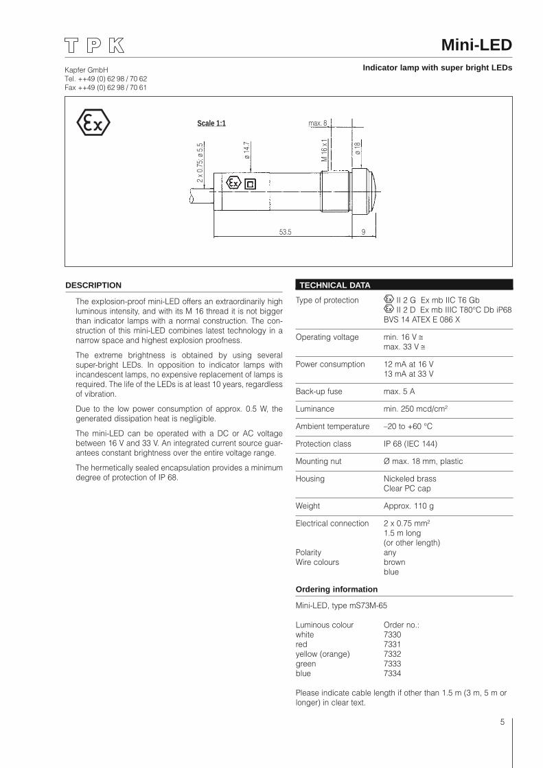
Mini-LEDIndicator lamp with super bright LEDs
Scale 1:1 max. 8
2 x
0.75
; ø 5
.5
ø 14
.7
ø 18
M 1
6 x 1
53.5 9
DESCRIPTION
The explosion-proof mini-LED offers an extraordinarily high luminous intensity, and with its M 16 thread it is not bigger than indicator lamps with a normal construction. The con-struction of this mini-LED combines latest technology in a narrow space and highest explosion proofness.
The extreme brightness is obtained by using several super-bright LEDs. In opposition to indicator lamps with incandescent lamps, no expensive replacement of lamps is required. The life of the LEDs is at least 10 years, regardless of vibration.
Due to the low power consumption of approx. 0.5 W, the generated dissipation heat is negligible.
The mini-LED can be operated with a DC or AC voltage between 16 V and 33 V. An integrated current source guar-antees constant brightness over the entire voltage range.
The hermetically sealed encapsulation provides a minimum degree of protection of IP 68.
TECHNICAL DATA
Type of protection II 2 G Ex mb IIC T6 Gb II 2 D Ex mb IIIC T80°C Db iP68 BVS 14 ATEX E 086 X
Operating voltage min. 16 V ≅ max. 33 V ≅
Power consumption 12 mA at 16 V 13 mA at 33 V
Back-up fuse max. 5 A
Luminance min. 250 mcd/cm²
Ambient temperature –20 to +60 °C
Protection class IP 68 (IEC 144)
Mounting nut Ø max. 18 mm, plastic
Housing Nickeled brass Clear PC cap
Weight Approx. 110 g
Electrical connection 2 x 0.75 mm² 1.5 m long (or other length)Polarity anyWire colours brown blue
Ordering information
Mini-LED, type mS73M-65
Luminous colour Order no.: white 7330red 7331yellow (orange) 7332green 7333blue 7334
Please indicate cable length if other than 1.5 m (3 m, 5 m or longer) in clear text.
Kapfer GmbHTel. ++49 (0) 62 98 / 70 62Fax ++49 (0) 62 98 / 70 61
6
Scale 1:1 max. 8
2 x
0.75
; ø 5
.5
ø 14
.7
ø 18
M 1
6 x 1
53.5 9
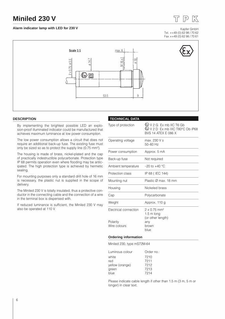
Miniled 230 VAlarm indicator lamp with LED for 230 V
DESCRIPTION
By implementing the brightest possible LED an explo-sion-proof illuminated indicator could be manufactured that achieves maximum luminance at low power consumption.
The low power consumption allows a circuit that does not require an additional back-up fuse. The existing fuse must only be sized so as to protect the supply line (0.75 mm²).
The housing is made of brass, nickel-plated and the cap of practically indestructible polycarbonate. Protection type IP 68 permits operation even where flooding may be antic-ipated. The high protection type is achieved by hermetic sealing.
For mounting purposes only a standard drill hole of 16 mm is necessary, the plastic nut is supplied in the scope of delivery.
The Miniled 230 V is totally insulated, thus a protective con-ductor in the connecting cable and the connection of a wire in the terminal box is dispensed with.
If reduced luminance is sufficient, the Miniled 230 V may also be operated at 110 V.
TECHNICAL DATA
Type of protection II 2 G Ex mb IIC T6 Gb II 2 D Ex mb IIIC T80°C Db iP68 BVS 14 ATEX E 086 X
Operating voltage max. 230 V ≅ 50–60 Hz
Power consumption Approx. 5 mA
Back-up fuse Not required
Ambient temperature –20 to +40 °C
Protection class IP 68 ( IEC 144)
Mounting nut Plastic Ø max. 18 mm
Housing Nickeled brass
Cap Polycarbonate
Weight Approx. 110 g
Electrical connection 2 x 0.75 mm² 1.5 m long (or other length)Polarity anyWire colours brown blue
Ordering information
Miniled 230, type mS72M-64
Luminous colour Order no.:white 7210red 7211yellow (orange) 7212green 7213blue 7214
Please indicate cable length if other than 1.5 m (3 m, 5 m or longer) in clear text.
Kapfer GmbHTel. ++49 (0) 62 98 / 70 62Fax ++49 (0) 62 98 / 70 61
7
MiniFlash
Scale 1:1Shortened lengthdrawn
28.3
20
25
ø 44
ø 40
ø 7
ø 15 ... 24
3 x 0.75 mm2
36.8
52
48 x
48
230
V: 1
2824
V A
C/DC
: 137
Mounting withassembly kit
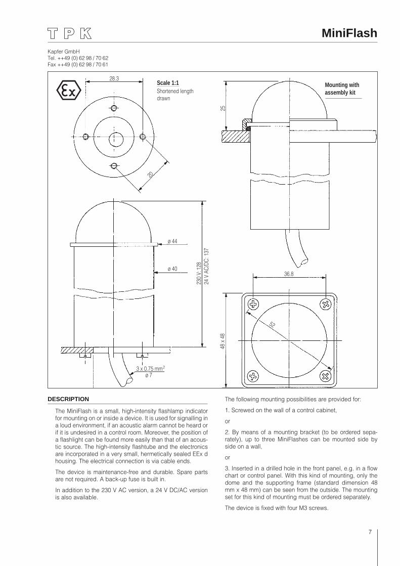
DESCRIPTION
The MiniFlash is a small, high-intensity flashlamp indicator for mounting on or inside a device. It is used for signalling in a loud environment, if an acoustic alarm cannot be heard or if it is undesired in a control room. Moreover, the position of a flashlight can be found more easily than that of an acous-tic source. The high-intensity flashtube and the electronics are incorporated in a very small, hermetically sealed EEx d housing. The electrical connection is via cable ends.
The device is maintenance-free and durable. Spare parts are not required. A back-up fuse is built in.
In addition to the 230 V AC version, a 24 V DC/AC version is also available.
The following mounting possibilities are provided for:
1. Screwed on the wall of a control cabinet,
or
2. By means of a mounting bracket (to be ordered sepa-rately), up to three MiniFlashes can be mounted side by side on a wall,
or
3. Inserted in a drilled hole in the front panel, e.g. in a flow chart or control panel. With this kind of mounting, only the dome and the supporting frame (standard dimension 48 mm x 48 mm) can be seen from the outside. The mounting set for this kind of mounting must be ordered separately.
The device is fixed with four M3 screws.
Kapfer GmbHTel. ++49 (0) 62 98 / 70 62Fax ++49 (0) 62 98 / 70 61
8
Ordering information
MiniFlash
Type dS63A-1. 40 BL
Order no.:
63120 . .
1 = red 2 = yellow 3 = green 4 = blue 6 = colourless
1 = 230 VAC 5 = 24 VDC
Mounting set
For mounting in a drilled hole, consisting of supporting frame (aluminium, hard-coated), O-ring, four M3 screws, nuts and lock washers made of VA.
Order no.: 99 63 05
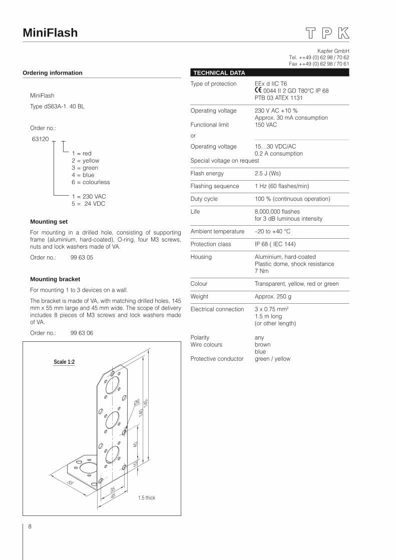
Mounting bracket
For mounting 1 to 3 devices on a wall.
The bracket is made of VA, with matching drilled holes, 145 mm x 55 mm large and 45 mm wide. The scope of delivery includes 8 pieces of M3 screws and lock washers made of VA.
Order no.: 99 63 06
TECHNICAL DATA
Type of protection EEx d IIC T6 0044 II 2 GD T80°C IP 68 PTB 03 ATEX 1131
Operating voltage 230 V AC +10 % Approx. 30 mA consumptionFunctional limit 150 VAC
or
Operating voltage 15…30 VDC/AC 0.2 A consumptionSpecial voltage on request
Flash energy 2.5 J (Ws)
Flashing sequence 1 Hz (60 flashes/min)
Duty cycle 100 % (continuous operation)
Life 8,000,000 flashes for 3 dB luminous intensity
Ambient temperature –20 to +40 °C
Protection class IP 68 ( IEC 144)
Housing Aluminium, hard-coated Plastic dome, shock resistance 7 Nm
Colour Transparent, yellow, red or green
Weight Approx. 250 g
Electrical connection 3 x 0.75 mm² 1.5 m long (or other length)
Polarity anyWire colours brown blueProtective conductor green / yellow
MiniFlash
55
145
140
10
4535
45
Ø 6
Scale 1:2
1.5 thick
Kapfer GmbHTel. ++49 (0) 62 98 / 70 62Fax ++49 (0) 62 98 / 70 61
9
Scale 1:1
20
83
ø 44
ø 40
ø 7
ø 15 ... 24
3 x 0.75 mm
2
28.3
MaxiLedLarge indicator lamp with LED
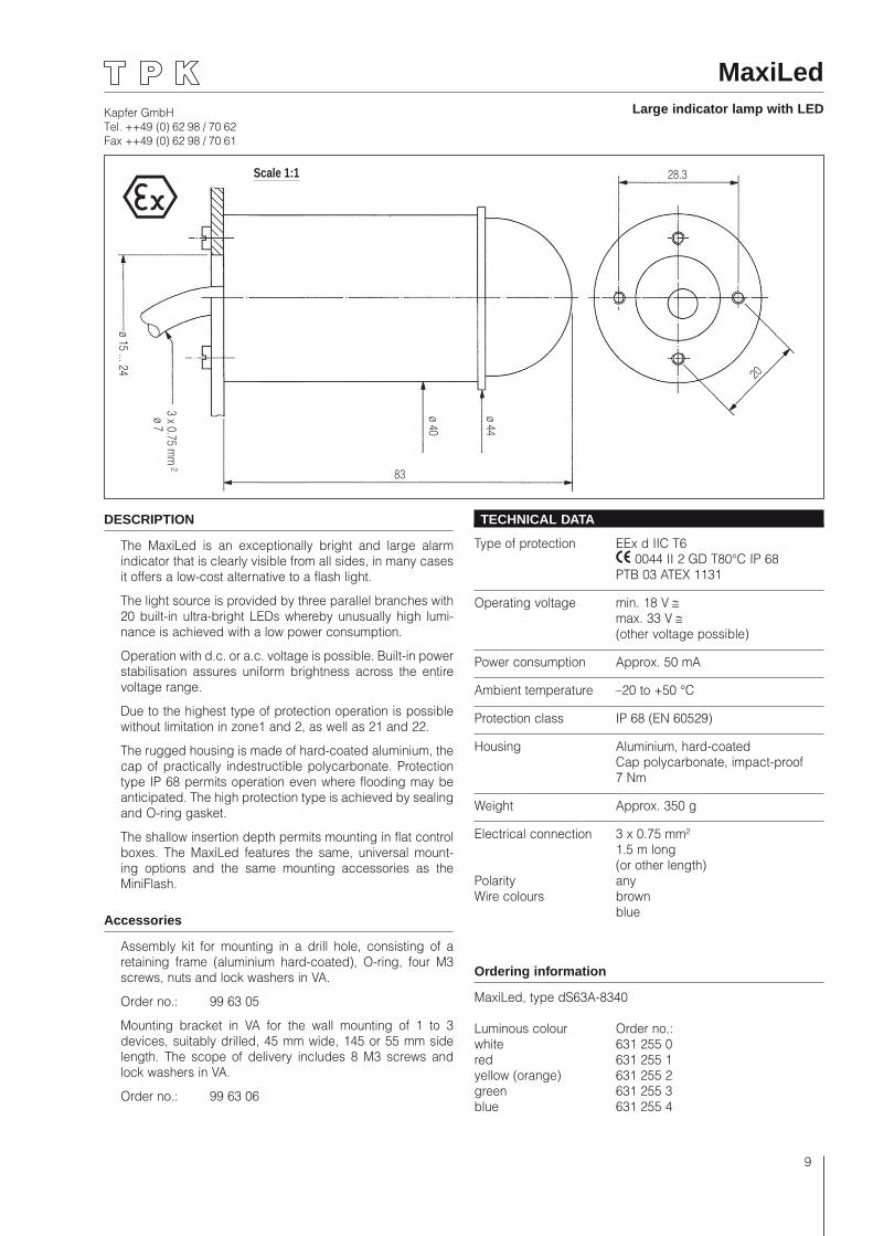
DESCRIPTION
The MaxiLed is an exceptionally bright and large alarm indicator that is clearly visible from all sides, in many cases it offers a low-cost alternative to a flash light.
The light source is provided by three parallel branches with 20 built-in ultra-bright LEDs whereby unusually high lumi-nance is achieved with a low power consumption.
Operation with d.c. or a.c. voltage is possible. Built-in power stabilisation assures uniform brightness across the entire voltage range.
Due to the highest type of protection operation is possible without limitation in zone1 and 2, as well as 21 and 22.
The rugged housing is made of hard-coated aluminium, the cap of practically indestructible polycarbonate. Protection type IP 68 permits operation even where flooding may be anticipated. The high protection type is achieved by sealing and O-ring gasket.
The shallow insertion depth permits mounting in flat control boxes. The MaxiLed features the same, universal mount-ing options and the same mounting accessories as the MiniFlash.
Accessories
Assembly kit for mounting in a drill hole, consisting of a retaining frame (aluminium hard-coated), O-ring, four M3 screws, nuts and lock washers in VA.
Order no.: 99 63 05
Mounting bracket in VA for the wall mounting of 1 to 3 devices, suitably drilled, 45 mm wide, 145 or 55 mm side length. The scope of delivery includes 8 M3 screws and lock washers in VA.
Order no.: 99 63 06
TECHNICAL DATA
Type of protection EEx d IIC T6 0044 II 2 GD T80°C IP 68 PTB 03 ATEX 1131
Operating voltage min. 18 V ≅ max. 33 V ≅ (other voltage possible)
Power consumption Approx. 50 mA
Ambient temperature –20 to +50 °C
Protection class IP 68 (EN 60529)
Housing Aluminium, hard-coated Cap polycarbonate, impact-proof 7 Nm
Weight Approx. 350 g
Electrical connection 3 x 0.75 mm² 1.5 m long (or other length)Polarity anyWire colours brown blue
Ordering information
MaxiLed, type dS63A-8340
Luminous colour Order no.: white 631 255 0red 631 255 1yellow (orange) 631 255 2green 631 255 3blue 631 255 4
Kapfer GmbHTel. ++49 (0) 62 98 / 70 62Fax ++49 (0) 62 98 / 70 61
10
MaxiLed 230 VLarge indicator lamp with LED
Scale 1:1
20
83
ø 44
ø 40
ø 7
ø 15 ... 24
3 x 0.75 mm
2
28.3
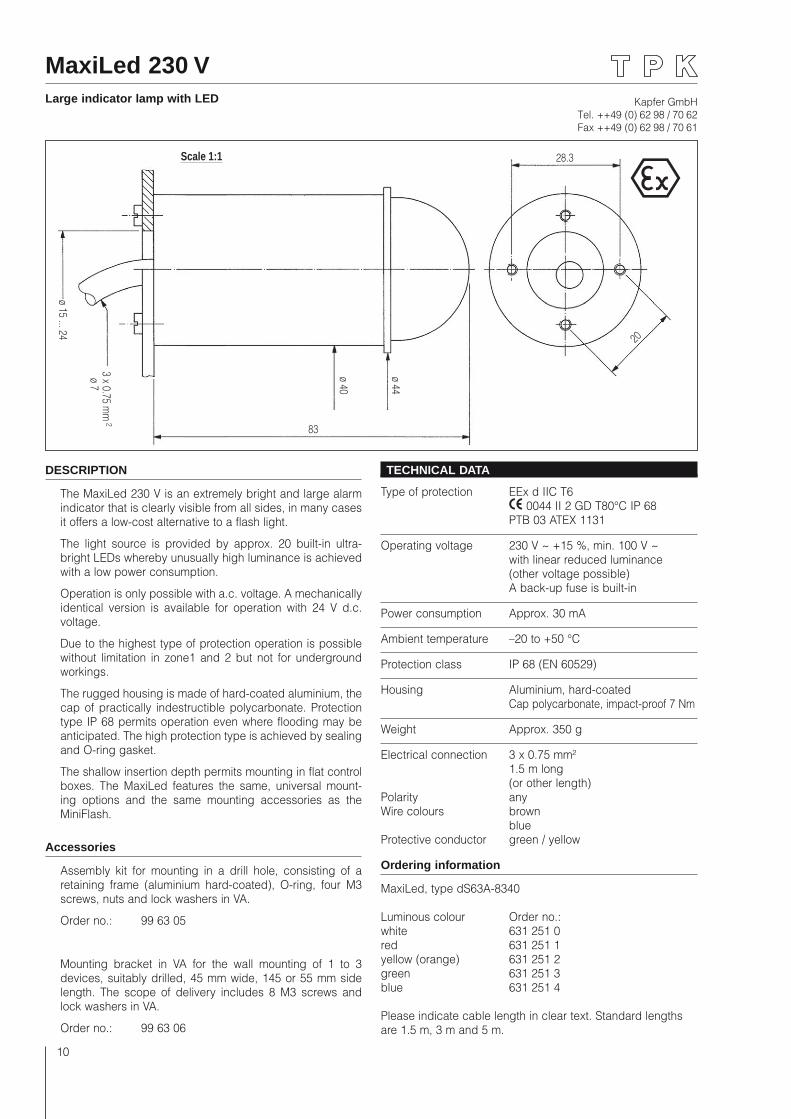
DESCRIPTION
The MaxiLed 230 V is an extremely bright and large alarm indicator that is clearly visible from all sides, in many cases it offers a low-cost alternative to a flash light.
The light source is provided by approx. 20 built-in ultra-bright LEDs whereby unusually high luminance is achieved with a low power consumption.
Operation is only possible with a.c. voltage. A mechanically identical version is available for operation with 24 V d.c. voltage.
Due to the highest type of protection operation is possible without limitation in zone1 and 2 but not for underground workings.
The rugged housing is made of hard-coated aluminium, the cap of practically indestructible polycarbonate. Protection type IP 68 permits operation even where flooding may be anticipated. The high protection type is achieved by sealing and O-ring gasket.
The shallow insertion depth permits mounting in flat control boxes. The MaxiLed features the same, universal mount-ing options and the same mounting accessories as the MiniFlash.
Accessories
Assembly kit for mounting in a drill hole, consisting of a retaining frame (aluminium hard-coated), O-ring, four M3 screws, nuts and lock washers in VA.
Order no.: 99 63 05
Mounting bracket in VA for the wall mounting of 1 to 3 devices, suitably drilled, 45 mm wide, 145 or 55 mm side length. The scope of delivery includes 8 M3 screws and lock washers in VA.
Order no.: 99 63 06
TECHNICAL DATA
Type of protection EEx d IIC T6 0044 II 2 GD T80°C IP 68 PTB 03 ATEX 1131
Operating voltage 230 V ~ +15 %, min. 100 V ~ with linear reduced luminance (other voltage possible) A back-up fuse is built-in
Power consumption Approx. 30 mA
Ambient temperature –20 to +50 °C
Protection class IP 68 (EN 60529)
Housing Aluminium, hard-coated Cap polycarbonate, impact-proof 7 Nm
Weight Approx. 350 g
Electrical connection 3 x 0.75 mm² 1.5 m long (or other length)Polarity anyWire colours brown blueProtective conductor green / yellow
Ordering information
MaxiLed, type dS63A-8340
Luminous colour Order no.: white 631 251 0red 631 251 1yellow (orange) 631 251 2green 631 251 3blue 631 251 4
Please indicate cable length in clear text. Standard lengths are 1.5 m, 3 m and 5 m.
Kapfer GmbHTel. ++49 (0) 62 98 / 70 62Fax ++49 (0) 62 98 / 70 61
11
Insid
e ø
16
72.5
ø 294 x M3 x 8
Bolt circle ø 22
ø 15
SW
13
2 x
0.75
; ø
5,5
Scale 1:1
NEW
DESCRIPTION
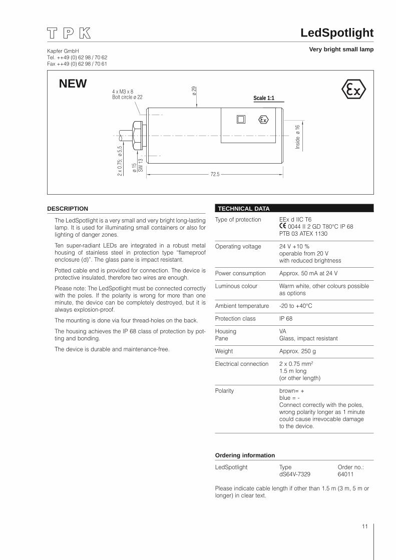
The LedSpotlight is a very small and very bright long-lasting lamp. It is used for illuminating small containers or also for lighting of danger zones.
Ten super-radiant LEDs are integrated in a robust metal housing of stainless steel in protection type “flameproof enclosure (d)”. The glass pane is impact resistant.
Potted cable end is provided for connection. The device is protective insulated, therefore two wires are enough.
Please note: The LedSpotlight must be connected correctly with the poles. If the polarity is wrong for more than one minute, the device can be completely destroyed, but it is always explosion-proof.
The mounting is done via four thread-holes on the back.
The housing achieves the IP 68 class of protection by pot-ting and bonding.
The device is durable and maintenance-free.
TECHNICAL DATA
Type of protection EEx d IIC T6 0044 II 2 GD T80°C IP 68 PTB 03 ATEX 1130
Operating voltage 24 V +10 % operable from 20 V with reduced brightness
Power consumption Approx. 50 mA at 24 V
Luminous colour Warm white, other colours possible as options
Ambient temperature -20 to +40°C
Protection class IP 68
Housing VA Pane Glass, impact resistant
Weight Approx. 250 g
Electrical connection 2 x 0.75 mm² 1.5 m long (or other length)
Polarity brown= + blue = - Connect correctly with the poles, wrong polarity longer as 1 minute could cause irrevocable damage to the device.
Ordering information
LedSpotlight Type Order no.: dS64V-7329 64011
Please indicate cable length if other than 1.5 m (3 m, 5 m or longer) in clear text.
LedSpotlightVery bright small lamp
Kapfer GmbHTel. ++49 (0) 62 98 / 70 62Fax ++49 (0) 62 98 / 70 61
12
Numerical indicator22Seven-segment indicator in VA
Scale 1:1max. 10
10 x
0.5
; ø 10
ø 20
.5
ø 26
.5
M22
x 1
41.5 12
O-ring
10
purple white
grey
red
black
blue
orangepink
DESCRIPTION
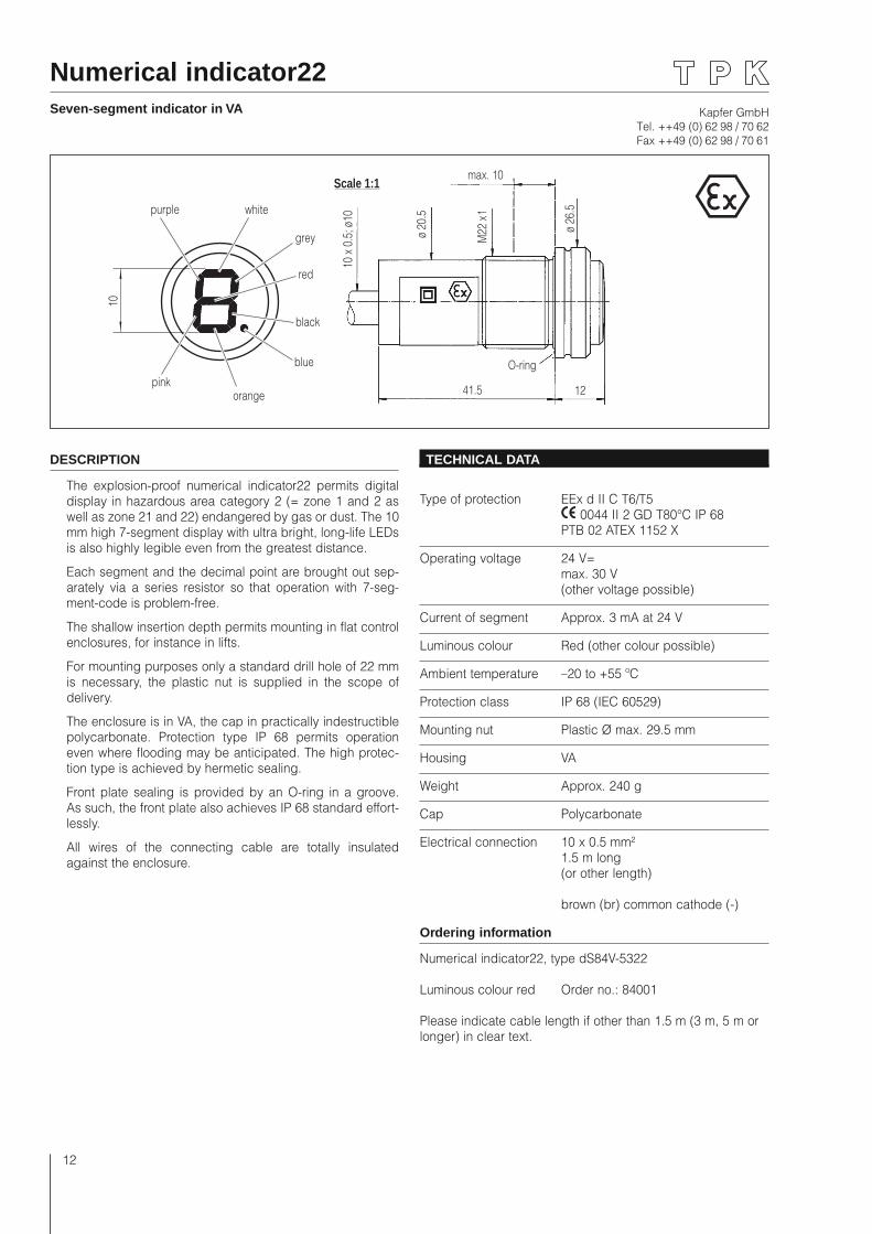
The explosion-proof numerical indicator22 permits digital display in hazardous area category 2 (= zone 1 and 2 as well as zone 21 and 22) endangered by gas or dust. The 10 mm high 7-segment display with ultra bright, long-life LEDs is also highly legible even from the greatest distance.
Each segment and the decimal point are brought out sep-arately via a series resistor so that operation with 7-seg-ment-code is problem-free.
The shallow insertion depth permits mounting in flat control enclosures, for instance in lifts.
For mounting purposes only a standard drill hole of 22 mm is necessary, the plastic nut is supplied in the scope of delivery.
The enclosure is in VA, the cap in practically indestructible polycarbonate. Protection type IP 68 permits operation even where flooding may be anticipated. The high protec-tion type is achieved by hermetic sealing.
Front plate sealing is provided by an O-ring in a groove. As such, the front plate also achieves IP 68 standard effort-lessly.
All wires of the connecting cable are totally insulated against the enclosure.
TECHNICAL DATA
Type of protection EEx d II C T6/T5 0044 II 2 GD T80°C IP 68 PTB 02 ATEX 1152 X
Operating voltage 24 V= max. 30 V (other voltage possible)
Current of segment Approx. 3 mA at 24 V
Luminous colour Red (other colour possible)
Ambient temperature –20 to +55 ºC
Protection class IP 68 (IEC 60529)
Mounting nut Plastic Ø max. 29.5 mm
Housing VA
Weight Approx. 240 g
Cap Polycarbonate
Electrical connection 10 x 0.5 mm² 1.5 m long (or other length)
brown (br) common cathode (-)
Ordering information
Numerical indicator22, type dS84V-5322
Luminous colour red Order no.: 84001
Please indicate cable length if other than 1.5 m (3 m, 5 m or longer) in clear text.
Kapfer GmbHTel. ++49 (0) 62 98 / 70 62Fax ++49 (0) 62 98 / 70 61
13
Numerical indicatorTwo-digit and three-digit
Scale 1:1
15
12 x
0.5
mm
2
ø 11
301744
ø 45
ø 45
SW 4
1
Pg 2
9ø
37
ø 40
9
a
CathodeHundredsred
CathodeTensbrown
CathodeUnitswhite
b
c
d
e
f g
DP
CathodeTensblue
CathodeUnitspink
a b c d e f g DP
trans
-pa
rent
oran
ge red
grey
brow
nbe
ige
white
lilac
blac
k n.
c.
oran
gebl
ack
beig
egr
eybl
ue lilac
pink
trans
-pa
rent
a b c d e f g DP
DESCRIPTION
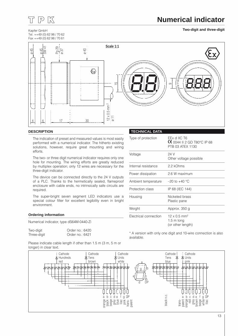
The indication of preset and measured values is most easily performed with a numerical indicator. The hitherto existing solutions, however, require great mounting and wiring efforts.
The two- or three digit numerical indicator requires only one hole for mounting. The wiring efforts are greatly reduced by multiplex operation; only 12 wires are necessary for the three-digit indicator.
The device can be connected directly to the 24 V outputs of a PLC. Thanks to the hermetically sealed, flameproof enclosure with cable ends, no intrinsically safe circuits are required.
The super-bright seven segment LED indicators use a special colour filter for excellent legibility even in bright environment.
Ordering information
Numerical indicator, type dS64M-0440-Zi
Two-digit Order no.: 6420Three-digit Order no.: 6421
Please indicate cable length if other than 1.5 m (3 m, 5 m or longer) in clear text.
TECHNICAL DATA
Type of protection EEx d IIC T6 0044 II 2 GD T80°C IP 68 PTB 03 ATEX 1130
Voltage 24 V Other voltage possible
Internal resistance 2.2 kOhms
Power dissipation 2.6 W maximum
Ambient temperature –20 to +40 °C
Protection class IP 68 (IEC 144)
Housing Nickeled brass Plastic pane
Weight Approx. 350 g
Electrical connection 12 x 0.5 mm² 1.5 m long (or other length)
* A version with only one digit and 10-wire connection is also available.
Kapfer GmbHTel. ++49 (0) 62 98 / 70 62Fax ++49 (0) 62 98 / 70 61
14
Numerical indicator One digit and minus
Scale 1:1
15
10 x
0.5
mm
2
ø 11
301744
ø 45
ø 45
SW 4
1
Pg 2
9ø
37
ø 40
b
c
d
e
f g
a
minus
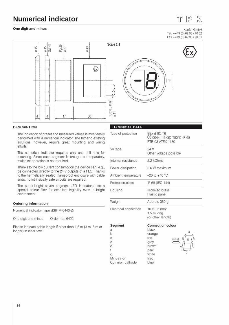
DESCRIPTION
The indication of preset and measured values is most easily performed with a numerical indicator. The hitherto existing solutions, however, require great mounting and wiring efforts.
The numerical indicator requires only one drill hole for mounting. Since each segment is brought out separately, multiplex operation is not required.
Thanks to the low current consumption the device can, e.g., be connected directly to the 24 V outputs of a PLC. Thanks to the hermetically sealed, flameproof enclosure with cable ends, no intrinsically safe circuits are required.
The super-bright seven segment LED indicators use a special colour filter for excellent legibility even in bright environment.
Ordering information
Numerical indicator, type dS64M-0440-Zi
One digit and minus Order no.: 6422
Please indicate cable length if other than 1.5 m (3 m, 5 m or longer) in clear text.
TECHNICAL DATA
Type of protection EEx d IIC T6 0044 II 2 GD T80°C IP 68 PTB 03 ATEX 1130
Voltage 24 V Other voltage possible
Internal resistance 2.2 kOhms
Power dissipation 2.6 W maximum
Ambient temperature –20 to +40 °C
Protection class IP 68 (IEC 144)
Housing Nickeled brass Plastic pane
Weight Approx. 350 g
Electrical connection 10 x 0.5 mm² 1.5 m long (or other length)
Segment Connection coloura blackb orangec redd greye brownf pinkg whiteMinus sign lilacCommon cathode blue
Kapfer GmbHTel. ++49 (0) 62 98 / 70 62Fax ++49 (0) 62 98 / 70 61
15
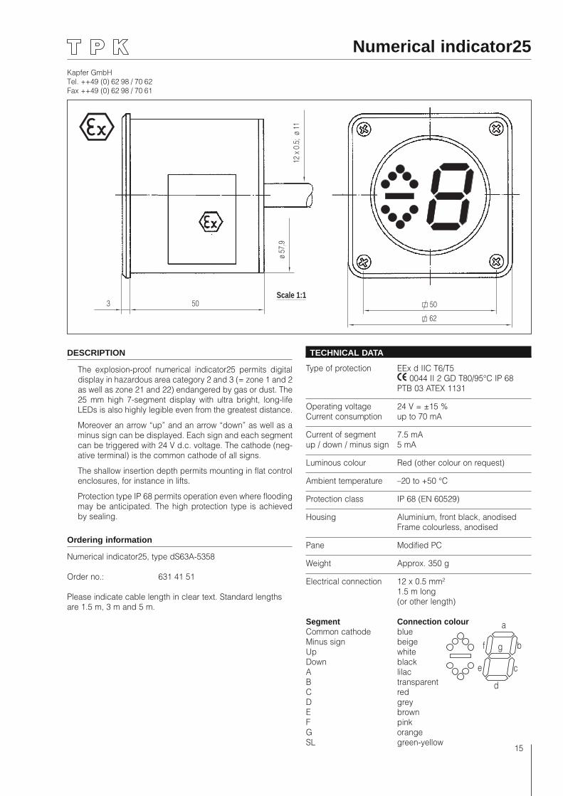
Numerical indicator25
Scale 1:150
62
312
x 0
.5;
ø 11
ø 57
.9
50
DESCRIPTION
The explosion-proof numerical indicator25 permits digital display in hazardous area category 2 and 3 (= zone 1 and 2 as well as zone 21 and 22) endangered by gas or dust. The 25 mm high 7-segment display with ultra bright, long-life LEDs is also highly legible even from the greatest distance.
Moreover an arrow “up” and an arrow “down” as well as a minus sign can be displayed. Each sign and each segment can be triggered with 24 V d.c. voltage. The cathode (neg-ative terminal) is the common cathode of all signs.
The shallow insertion depth permits mounting in flat control enclosures, for instance in lifts.
Protection type IP 68 permits operation even where flooding may be anticipated. The high protection type is achieved by sealing.
Ordering information
Numerical indicator25, type dS63A-5358
Order no.: 631 41 51
Please indicate cable length in clear text. Standard lengths are 1.5 m, 3 m and 5 m.
TECHNICAL DATA
Type of protection EEx d IIC T6/T5 0044 II 2 GD T80/95°C IP 68 PTB 03 ATEX 1131
Operating voltage 24 V = ±15 %Current consumption up to 70 mA
Current of segment 7.5 mA up / down / minus sign 5 mA
Luminous colour Red (other colour on request)
Ambient temperature –20 to +50 °C
Protection class IP 68 (EN 60529)
Housing Aluminium, front black, anodised Frame colourless, anodised
Pane Modified PC
Weight Approx. 350 g
Electrical connection 12 x 0.5 mm² 1.5 m long (or other length)
Segment Connection colourCommon cathode blueMinus sign beigeUp whiteDown blackA lilacB transparentC redD greyE brownF pinkG orangeSL green-yellow
b
c
d
e
f g
a
Kapfer GmbHTel. ++49 (0) 62 98 / 70 62Fax ++49 (0) 62 98 / 70 61
16
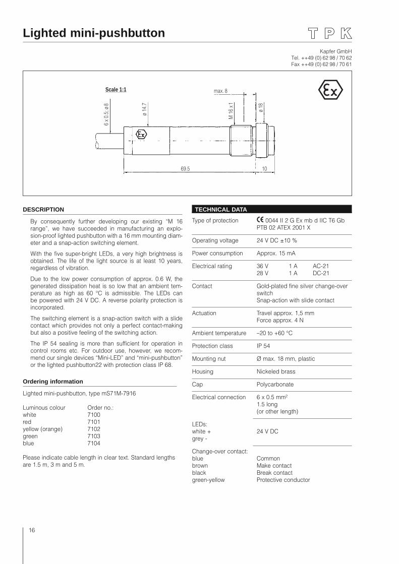
Lighted mini-pushbutton
Scale 1:1 max. 8
6 x
0.5;
ø 8
ø 14
.7
ø 18
M 1
6 x 1
69.5 10
DESCRIPTION
By consequently further developing our existing “M 16 range”, we have succeeded in manufacturing an explo-sion-proof lighted pushbutton with a 16 mm mounting diam-eter and a snap-action switching element.
With the five super-bright LEDs, a very high brightness is obtained. The life of the light source is at least 10 years, regardless of vibration.
Due to the low power consumption of approx. 0.6 W, the generated dissipation heat is so low that an ambient tem-perature as high as 60 °C is admissible. The LEDs can be powered with 24 V DC. A reverse polarity protection is incorporated.
The switching element is a snap-action switch with a slide contact which provides not only a perfect contact-making but also a positive feeling of the switching action.
The IP 54 sealing is more than sufficient for operation in control rooms etc. For outdoor use, however, we recom-mend our single devices “Mini-LED” and “mini-pushbutton” or the lighted pushbutton22 with protection class IP 68.
Ordering information
Lighted mini-pushbutton, type mS71M-7916
Luminous colour Order no.:white 7100red 7101yellow (orange) 7102green 7103blue 7104
Please indicate cable length in clear text. Standard lengths are 1.5 m, 3 m and 5 m.
TECHNICAL DATA
Type of protection 0044 II 2 G Ex mb d IIC T6 Gb PTB 02 ATEX 2001 X
Operating voltage 24 V DC ±10 %
Power consumption Approx. 15 mA
Electrical rating 36 V 1 A AC-21 28 V 1 A DC-21
Contact Gold-plated fine silver change-over switch
Snap-action with slide contact
Actuation Travel approx. 1,5 mm Force approx. 4 N
Ambient temperature –20 to +60 °C
Protection class IP 54
Mounting nut Ø max. 18 mm, plastic
Housing Nickeled brass
Cap Polycarbonate
Electrical connection 6 x 0.5 mm² 1.5 long (or other length)
LEDs:white + 24 V DCgrey -
Change-over contact:blue Commonbrown Make contactblack Break contactgreen-yellow Protective conductor
Kapfer GmbHTel. ++49 (0) 62 98 / 70 62Fax ++49 (0) 62 98 / 70 61
17
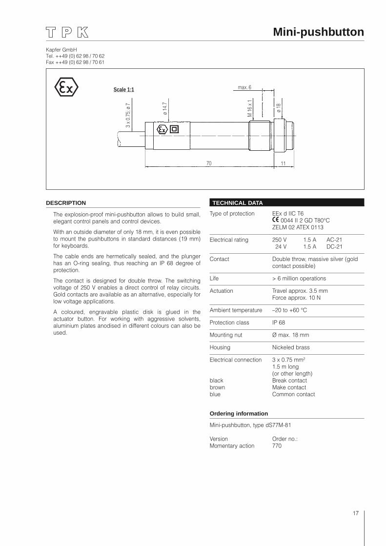
Mini-pushbutton
Scale 1:1 max. 6
3 x
0.75
; ø 7
ø 14
.7
ø 18
M 1
6 x 1
70 11
DESCRIPTION
The explosion-proof mini-pushbutton allows to build small, elegant control panels and control devices.
With an outside diameter of only 18 mm, it is even possible to mount the pushbuttons in standard distances (19 mm) for keyboards.
The cable ends are hermetically sealed, and the plunger has an O-ring sealing, thus reaching an IP 68 degree of protection.
The contact is designed for double throw. The switching voltage of 250 V enables a direct control of relay circuits. Gold contacts are available as an alternative, especially for low voltage applications.
A coloured, engravable plastic disk is glued in the actuator button. For working with aggressive solvents, aluminium plates anodised in different colours can also be used.
TECHNICAL DATA
Type of protection EEx d IIC T6 0044 II 2 GD T80°C ZELM 02 ATEX 0113
Electrical rating 250 V 1.5 A AC-21 24 V 1.5 A DC-21
Contact Double throw, massive silver (gold contact possible)
Life > 6 million operations
Actuation Travel approx. 3.5 mm Force approx. 10 N
Ambient temperature –20 to +60 °C
Protection class IP 68
Mounting nut Ø max. 18 mm
Housing Nickeled brass
Electrical connection 3 x 0.75 mm² 1.5 m long (or other length)black Break contactbrown Make contactblue Common contact
Ordering information
Mini-pushbutton, type dS77M-81
Version Order no.:Momentary action 770
Kapfer GmbHTel. ++49 (0) 62 98 / 70 62Fax ++49 (0) 62 98 / 70 61
18
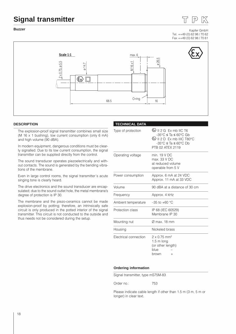
Signal transmitter Buzzer
Scale 1:1 max. 62
x 0.
75; ø
5.5
ø 14
.7 ø 26
.5
M 1
6 x 1
68.5 16O-ring
DESCRIPTION
The explosion-proof signal transmitter combines small size (M 16 x 1 bushing), low current consumption (only 6 mA) and high volume (90 dBA).
In modern equipment, dangerous conditions must be clear-ly signalled. Due to its low current consumption, the signal transmitter can be supplied directly from the control.
The sound transducer operates piezoelectrically and with-out contacts. The sound is generated by the bending vibra-tions of the membrane.
Even in large control rooms, the signal transmitter´s acute singing tone is clearly heard.
The drive electronics and the sound transducer are encap-sulated; due to the sound outlet hole, the metal membrane’s degree of protection is IP 30.
The membrane and the piezo-ceramics cannot be made explosion-proof by potting; therefore, an intrinsically safe circuit is only produced in the potted interior of the signal transmitter. This circuit is not conducted to the outside and thus needs not be considered during the setup.
TECHNICAL DATA
Type of protection II 2 G Ex mb IIC T6 -35°C ≤ Ta ≤ 60°C Gb II 2 D Ex mb IIIC T80°C -35°C ≤ Ta ≤ 60°C Db PTB 02 ATEX 2119
Operating voltage min. 19 V DC max. 33 V DC at reduced volume operable from 5 V
Power consumption Approx. 6 mA at 24 VDC Approx. 11 mA at 33 VDC
Volume 90 dBA at a distance of 30 cm
Frequency Approx. 4 kHz
Ambient temperature –35 to +60 °C
Protection class IP 68 (IEC 60529) Membrane IP 30
Mounting nut Ø max. 18 mm
Housing Nickeled brass
Electrical connection 2 x 0.75 mm² 1.5 m long (or other length) blue – brown +
Ordering information
Signal transmitter, type mS75M-83
Order no.: 753
Please indicate cable length if other than 1.5 m (3 m, 5 m or longer) in clear text.
Kapfer GmbHTel. ++49 (0) 62 98 / 70 62Fax ++49 (0) 62 98 / 70 61
19
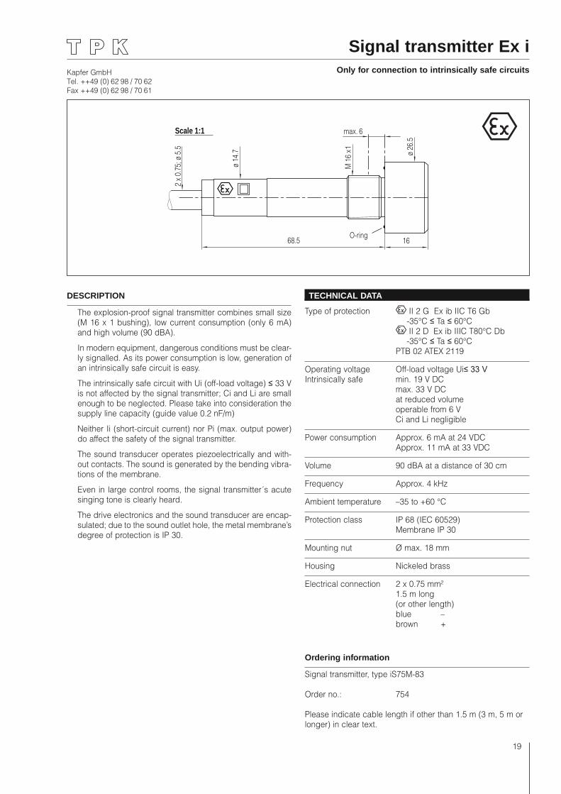
Signal transmitter Ex iOnly for connection to intrinsically safe circuits
Scale 1:1 max. 6
2 x
0.75
; ø 5
.5
ø 14
.7 ø 26
.5
M 1
6 x 1
68.5 16O-ring
DESCRIPTION
The explosion-proof signal transmitter combines small size (M 16 x 1 bushing), low current consumption (only 6 mA) and high volume (90 dBA).
In modern equipment, dangerous conditions must be clear-ly signalled. As its power consumption is low, generation of an intrinsically safe circuit is easy.
The intrinsically safe circuit with Ui (off-load voltage) ≤ 33 V is not affected by the signal transmitter; Ci and Li are small enough to be neglected. Please take into consideration the supply line capacity (guide value 0.2 nF/m)
Neither Ii (short-circuit current) nor Pi (max. output power) do affect the safety of the signal transmitter.
The sound transducer operates piezoelectrically and with-out contacts. The sound is generated by the bending vibra-tions of the membrane.
Even in large control rooms, the signal transmitter´s acute singing tone is clearly heard.
The drive electronics and the sound transducer are encap-sulated; due to the sound outlet hole, the metal membrane’s degree of protection is IP 30.
TECHNICAL DATA
Type of protection II 2 G Ex ib IIC T6 Gb -35°C ≤ Ta ≤ 60°C II 2 D Ex ib IIIC T80°C Db -35°C ≤ Ta ≤ 60°C PTB 02 ATEX 2119
Operating voltage Off-load voltage Ui≤ 33 V Intrinsically safe min. 19 V DC max. 33 V DC at reduced volume operable from 6 V Ci and Li negligible
Power consumption Approx. 6 mA at 24 VDC Approx. 11 mA at 33 VDC
Volume 90 dBA at a distance of 30 cm
Frequency Approx. 4 kHz
Ambient temperature –35 to +60 °C
Protection class IP 68 (IEC 60529) Membrane IP 30
Mounting nut Ø max. 18 mm
Housing Nickeled brass
Electrical connection 2 x 0.75 mm² 1.5 m long (or other length) blue – brown +
Ordering information
Signal transmitter, type iS75M-83
Order no.: 754
Please indicate cable length if other than 1.5 m (3 m, 5 m or longer) in clear text.
Kapfer GmbHTel. ++49 (0) 62 98 / 70 62Fax ++49 (0) 62 98 / 70 61
20
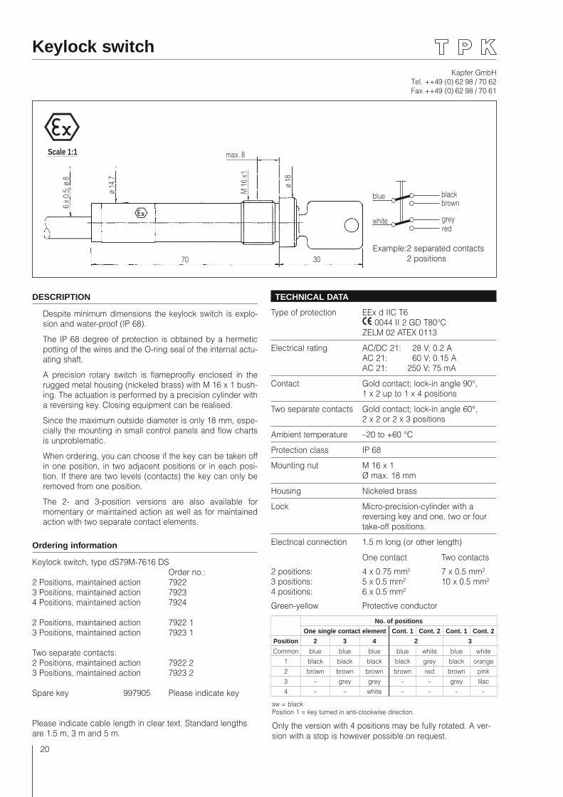
Keylock switch
Scale 1:1 max. 8
6 x
0.5;
ø 8
ø 14
.7
ø 18
M 1
6 x 1
70 30
DESCRIPTION
Despite minimum dimensions the keylock switch is explo-sion and water-proof (IP 68).
The IP 68 degree of protection is obtained by a hermetic potting of the wires and the O-ring seal of the internal actu-ating shaft.
A precision rotary switch is flameproofly enclosed in the rugged metal housing (nickeled brass) with M 16 x 1 bush-ing. The actuation is performed by a precision cylinder with a reversing key. Closing equipment can be realised.
Since the maximum outside diameter is only 18 mm, espe-cially the mounting in small control panels and flow charts is unproblematic.
When ordering, you can choose if the key can be taken off in one position, in two adjacent positions or in each posi-tion. If there are two levels (contacts) the key can only be removed from one position.
The 2- and 3-position versions are also available for momentary or maintained action as well as for maintained action with two separate contact elements.
Ordering information
Keylock switch, type dS79M-7616 DS Order no.:2 Positions, maintained action 79223 Positions, maintained action 79234 Positions, maintained action 7924
2 Positions, maintained action 7922 13 Positions, maintained action 7923 1
Two separate contacts:2 Positions, maintained action 7922 23 Positions, maintained action 7923 2
Spare key 997905 Please indicate key
Please indicate cable length in clear text. Standard lengths are 1.5 m, 3 m and 5 m.
TECHNICAL DATA
Type of protection EEx d IIC T6 0044 II 2 GD T80°C ZELM 02 ATEX 0113
Electrical rating AC/DC 21: 28 V; 0.2 A AC 21: 60 V; 0.15 A AC 21: 250 V; 75 mA
Contact Gold contact; lock-in angle 90°, 1 x 2 up to 1 x 4 positions
Two separate contacts Gold contact; lock-in angle 60°, 2 x 2 or 2 x 3 positions
Ambient temperature –20 to +60 °C
Protection class IP 68
Mounting nut M 16 x 1 Ø max. 18 mm
Housing Nickeled brass
Lock Micro-precision-cylinder with a reversing key and one, two or four take-off positions.
Electrical connection 1.5 m long (or other length)
One contact Two contacts
2 positions: 4 x 0.75 mm² 7 x 0.5 mm²3 positions: 5 x 0.5 mm² 10 x 0.5 mm²4 positions: 6 x 0.5 mm²
Green-yellow Protective conductor
sw = blackPosition 1 = key turned in anti-clockwise direction.
Only the version with 4 positions may be fully rotated. A ver-sion with a stop is however possible on request.
No. of positions
One single contact element Cont. 1 Cont. 2 Cont. 1 Cont. 2
Position 2 3 4 2 3
Common blue blue blue blue white blue white1 black black black black grey black orange2 brown brown brown brown red brown pink3 - grey grey - - grey lilac4 - - white - - - -
blue
whiteredgrey
brownblack
Example: 2 separated contacts 2 positions
Kapfer GmbHTel. ++49 (0) 62 98 / 70 62Fax ++49 (0) 62 98 / 70 61
21
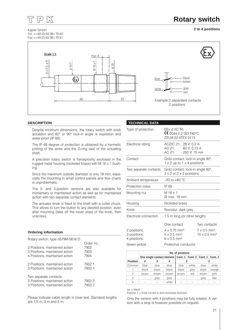
Rotary switch2 to 4 positions
Scale 1:1 max. 8
6 x
0.5;
ø 8
ø 14
.7
ø 18
M 1
6 x 1
49 23
DESCRIPTION
Despite minimum dimensions, the rotary switch with knob actuation and 60° or 90° lock-in angle is explosion and water-proof (IP 68).
The IP 68 degree of protection is obtained by a hermetic potting of the wires and the O-ring seal of the actuating shaft.
A precision rotary switch is flameproofly enclosed in the rugged metal housing (nickeled brass) with M 16 x 1 bush-ing.
Since the maximum outside diameter is only 18 mm, espe-cially the mounting in small control panels and flow charts is unproblematic.
The 2- and 3-position versions are also available for momentary or maintained action as well as for maintained action with two separate contact elements.
The actuator knob is fixed to the shaft with a collet chuck. This allows to turn the button to any desired position, even after mounting (take off the cover plate of the knob, then unscrew).
Ordering information
Rotary switch, type dS79M-5616 D Order no.:2 Positions, maintained action 79023 Positions, maintained action 79034 Positions, maintained action 7904
2 Positions, maintained action 7902 13 Positions, maintained action 7903 1
Two separate contacts:2 Positions, maintained action 7902 23 Positions, maintained action 7903 2
Please indicate cable length in clear text. Standard lengths are 1.5 m, 3 m and 5 m.
TECHNICAL DATA
Type of protection EEx d IIC T6 0044 II 2 GD T80°C ZELM 02 ATEX 0113
Electrical rating AC/DC 21: 28 V; 0.2 A AC 21: 60 V; 0.15 A AC 21: 250 V; 75 mA
Contact Gold contact; lock-in angle 90°, 1 x 2 up to 1 x 4 positions
Two separate contacts Gold contact; lock-in angle 60°, 2 x 2 or 2 x 3 positions
Ambient temperature –20 to +60 °C
Protection class IP 68
Mounting nut M 16 x 1 Ø max. 18 mm
Housing Nickeled brass
Knob Novodur, dark grey
Electrical connection 1.5 m long (or other length)
One contact Two contacts
2 positions: 4 x 0.75 mm² 7 x 0.5 mm²3 positions: 5 x 0.5 mm² 10 x 0.5 mm²4 positions: 6 x 0.5 mm²
Green-yellow Protective conductor
sw = blackPosition 1 = knob turned in anti-clockwise direction.
Only the version with 4 positions may be fully rotated. A ver-sion with a stop is however possible on request.
blue
whiteredgrey
brownblack
Example: 2 separated contacts 2 positions
No. of positions
One single contact element Cont. 1 Cont. 2 Cont. 1 Cont. 2
Position 2 3 4 2 3
Common blue blue blue blue white blue white1 black black black black grey black orange2 brown brown brown brown red brown pink3 - grey grey - - grey lilac4 - - white - - - -
Kapfer GmbHTel. ++49 (0) 62 98 / 70 62Fax ++49 (0) 62 98 / 70 61
22
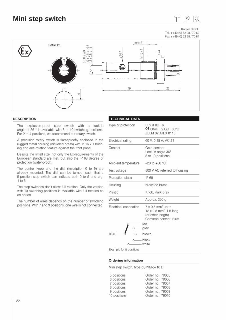
Mini step switch
Scale 1:1max. 8
12 x
0.5
; ø 1
1
ø 14
.7
ø 24
M 1
6 x 1
10
234910
x 0
.5; ø
10.
58
x 0.
5; ø
9
DESCRIPTION
The explosion-proof step switch with a lock-in angle of 36 ° is available with 5 to 10 switching positions. For 2 to 4 positions, we recommend our rotary switch.
A precision rotary switch is flameproofly enclosed in the rugged metal housing (nickeled brass) with M 16 x 1 bush-ing and anti-rotation feature against the front panel.
Despite the small size, not only the Ex-requirements of the European standard are met, but also the IP 68 degree of protection (water-proof).
The control knob and the dial (inscription 0 to 9) are already mounted. The dial can be turned, such that a 5-position step switch can indicate both 0 to 5 and e.g. 1 to 6.
The step switches don’t allow full rotation. Only the version with 10 switching positions is available with full rotation as an option.
The number of wires depends on the number of switching positions. With 7 and 9 positions, one wire is not connected.
TECHNICAL DATA
Type of protection EEx d IIC T6 0044 II 2 GD T80°C ZELM 02 ATEX 0113
Electrical rating 60 V; 0.15 A; AC 21
Contact Gold contact Lock-in angle 36° 5 to 10 positions
Ambient temperature –20 to +60 °C
Test voltage 500 V AC referred to housing
Protection class IP 68
Housing Nickeled brass
Plastic Knob, dark grey
Weight Approx. 290 g
Electrical connection 7 x 0.5 mm² up to 12 x 0.5 mm², 1.5 long (or other length) Common contact: Blue
Ordering information
Mini step switch, type dS79M-5716 D
5 positions Order no.: 79005 6 positions Order no.: 79006 7 positions Order no.: 79007 8 positions Order no.: 79008 9 positions Order no.: 7900910 positions Order no.: 79010
Example for 5 positions
redgrey
brown
blackwhite
blue
Kapfer GmbHTel. ++49 (0) 62 98 / 70 62Fax ++49 (0) 62 98 / 70 61
23
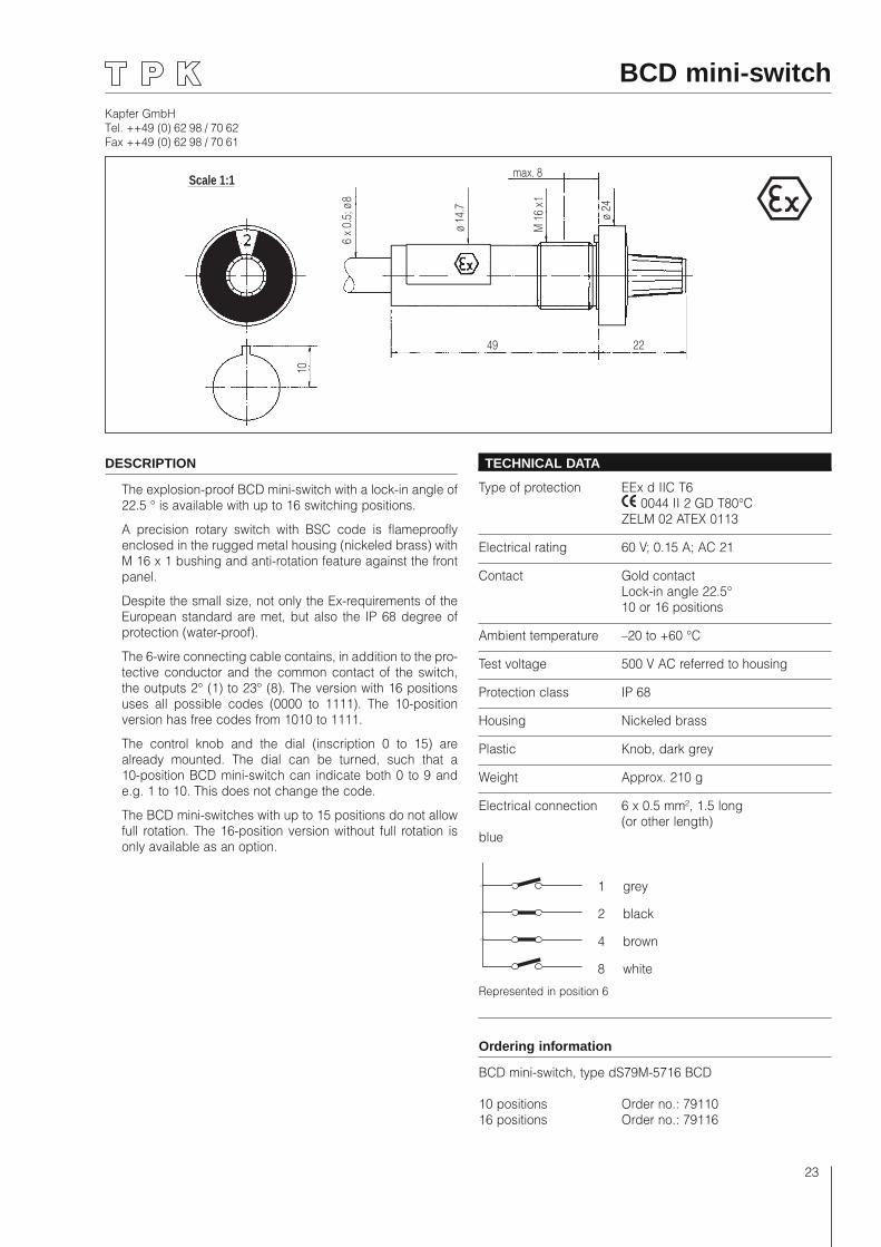
BCD mini-switch
DESCRIPTION
The explosion-proof BCD mini-switch with a lock-in angle of 22.5 ° is available with up to 16 switching positions.
A precision rotary switch with BSC code is flameproofly enclosed in the rugged metal housing (nickeled brass) with M 16 x 1 bushing and anti-rotation feature against the front panel.
Despite the small size, not only the Ex-requirements of the European standard are met, but also the IP 68 degree of protection (water-proof).
The 6-wire connecting cable contains, in addition to the pro-tective conductor and the common contact of the switch, the outputs 2° (1) to 23° (8). The version with 16 positions uses all possible codes (0000 to 1111). The 10-position version has free codes from 1010 to 1111.
The control knob and the dial (inscription 0 to 15) are already mounted. The dial can be turned, such that a 10-position BCD mini-switch can indicate both 0 to 9 and e.g. 1 to 10. This does not change the code.
The BCD mini-switches with up to 15 positions do not allow full rotation. The 16-position version without full rotation is only available as an option.
TECHNICAL DATA
Type of protection EEx d IIC T6 0044 II 2 GD T80°C ZELM 02 ATEX 0113
Electrical rating 60 V; 0.15 A; AC 21
Contact Gold contact Lock-in angle 22.5° 10 or 16 positions
Ambient temperature –20 to +60 °C
Test voltage 500 V AC referred to housing
Protection class IP 68
Housing Nickeled brass
Plastic Knob, dark grey
Weight Approx. 210 g
Electrical connection 6 x 0.5 mm², 1.5 long (or other length)blue
Ordering information
BCD mini-switch, type dS79M-5716 BCD
10 positions Order no.: 7911016 positions Order no.: 79116
Scale 1:1 max. 8
6 x
0.5;
ø 8
ø 14
.7
ø 24
M 1
6 x 1
10
2249
Represented in position 6
1 grey
2 black
4 brown
8 white
Kapfer GmbHTel. ++49 (0) 62 98 / 70 62Fax ++49 (0) 62 98 / 70 61
24
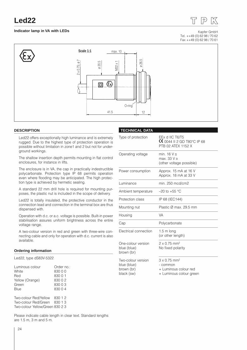
Led22Indicator lamp in VA with LEDs
Scale 1:1 max. 10
2 x
0.75
; ø 7
ø 20
.5
ø 26
.5
M22
x 1
41.5 12
O-ring
DESCRIPTION
Led22 offers exceptionally high luminance and is extremely rugged. Due to the highest type of protection operation is possible without limitation in zone1 and 2 but not for under-ground workings.
The shallow insertion depth permits mounting in flat control enclosures, for instance in lifts.
The enclosure is in VA, the cap in practically indestructible polycarbonate. Protection type IP 68 permits operation even where flooding may be anticipated. The high protec-tion type is achieved by hermetic sealing.
A standard 22 mm drill hole is required for mounting pur-poses, the plastic nut is included in the scope of delivery.
Led22 is totally insulated, the protective conductor in the connection lead and connection in the terminal box are thus dispensed with.
Operation with d.c. or a.c. voltage is possible. Built-in power stabilisation assures uniform brightness across the entire voltage range.
A two-colour version in red and green with three-wire con-necting cable and only for operation with d.c. current is also available.
Ordering information
Led22, type dS83V-5322
Luminous colour Order no.:White 830 0 0Red 830 0 1Yellow (Orange) 830 0 2Green 830 0 3Blue 830 0 4
Two-colour Red/Yellow 830 1 2Two-colour Red/Green 830 1 3Two-colour Yellow/Green 830 2 3
Please indicate cable length in clear text. Standard lengths are 1.5 m, 3 m and 5 m.
TECHNICAL DATA
Type of protection EEx d IIC T6/T5 0044 II 2 GD T80°C IP 68 PTB 02 ATEX 1152 X
Operating voltage min. 16 V ≅ max. 33 V ≅ (other voltage possible)
Power consumption Approx. 15 mA at 16 V Approx. 18 mA at 33 V
Luminance min. 250 mcd/cm2
Ambient temperature –20 to +55 °C
Protection class IP 68 (IEC144)
Mounting nut Plastic Ø max. 29.5 mm
Housing VA
Cap Polycarbonate
Electrical connection 1.5 m long (or other length)
One-colour version 2 x 0.75 mm²blue (blue) No fixed polaritybrown (br)
Two-colour version 3 x 0.75 mm²blue (blue) - commonbrown (br) + Luminous colour redblack (sw) + Luminous colour green
Kapfer GmbHTel. ++49 (0) 62 98 / 70 62Fax ++49 (0) 62 98 / 70 61
25
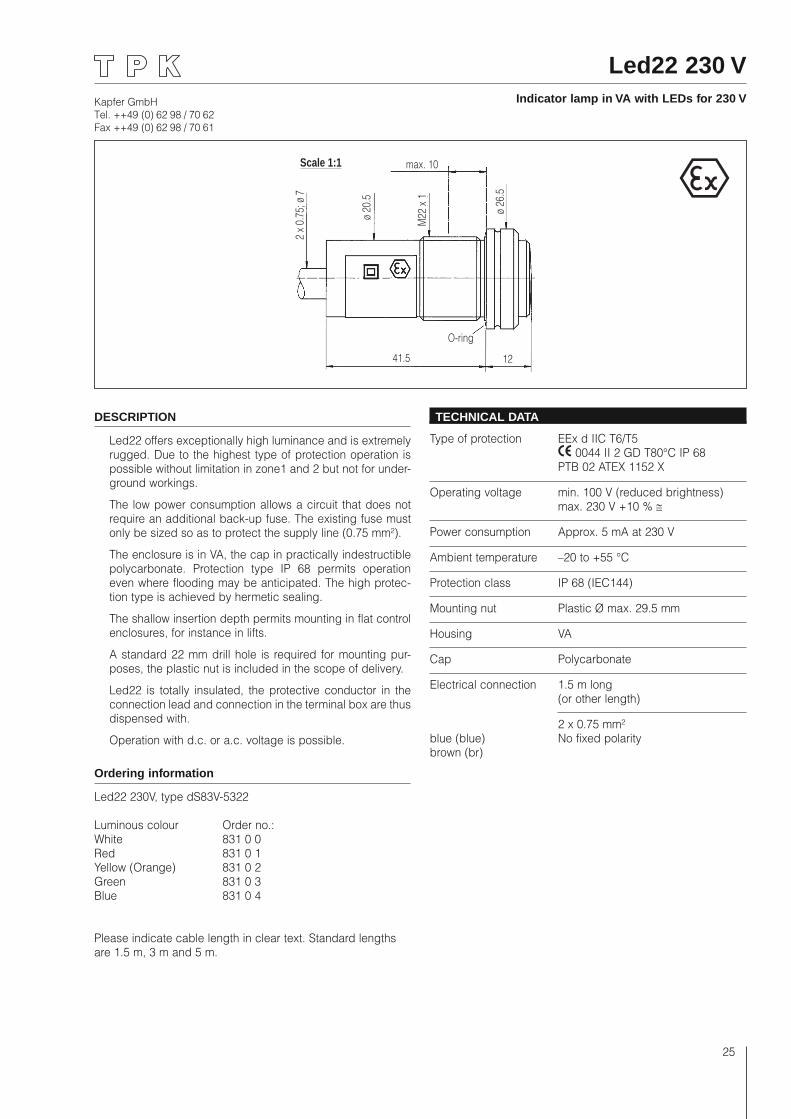
Led22 230 VIndicator lamp in VA with LEDs for 230 V
Scale 1:1 max. 10
2 x
0.75
; ø 7
ø 20
.5
ø 26
.5
M22
x 1
41.5 12
O-ring
DESCRIPTION
Led22 offers exceptionally high luminance and is extremely rugged. Due to the highest type of protection operation is possible without limitation in zone1 and 2 but not for under-ground workings.
The low power consumption allows a circuit that does not require an additional back-up fuse. The existing fuse must only be sized so as to protect the supply line (0.75 mm²).
The enclosure is in VA, the cap in practically indestructible polycarbonate. Protection type IP 68 permits operation even where flooding may be anticipated. The high protec-tion type is achieved by hermetic sealing.
The shallow insertion depth permits mounting in flat control enclosures, for instance in lifts.
A standard 22 mm drill hole is required for mounting pur-poses, the plastic nut is included in the scope of delivery.
Led22 is totally insulated, the protective conductor in the connection lead and connection in the terminal box are thus dispensed with.
Operation with d.c. or a.c. voltage is possible.
Ordering information
Led22 230V, type dS83V-5322
Luminous colour Order no.: White 831 0 0Red 831 0 1Yellow (Orange) 831 0 2Green 831 0 3Blue 831 0 4
Please indicate cable length in clear text. Standard lengths are 1.5 m, 3 m and 5 m.
TECHNICAL DATA
Type of protection EEx d IIC T6/T5 0044 II 2 GD T80°C IP 68 PTB 02 ATEX 1152 X
Operating voltage min. 100 V (reduced brightness) max. 230 V +10 % ≅
Power consumption Approx. 5 mA at 230 V
Ambient temperature –20 to +55 °C
Protection class IP 68 (IEC144)
Mounting nut Plastic Ø max. 29.5 mm
Housing VA
Cap Polycarbonate
Electrical connection 1.5 m long (or other length)
2 x 0.75 mm²blue (blue) No fixed polaritybrown (br)
Kapfer GmbHTel. ++49 (0) 62 98 / 70 62Fax ++49 (0) 62 98 / 70 61
26
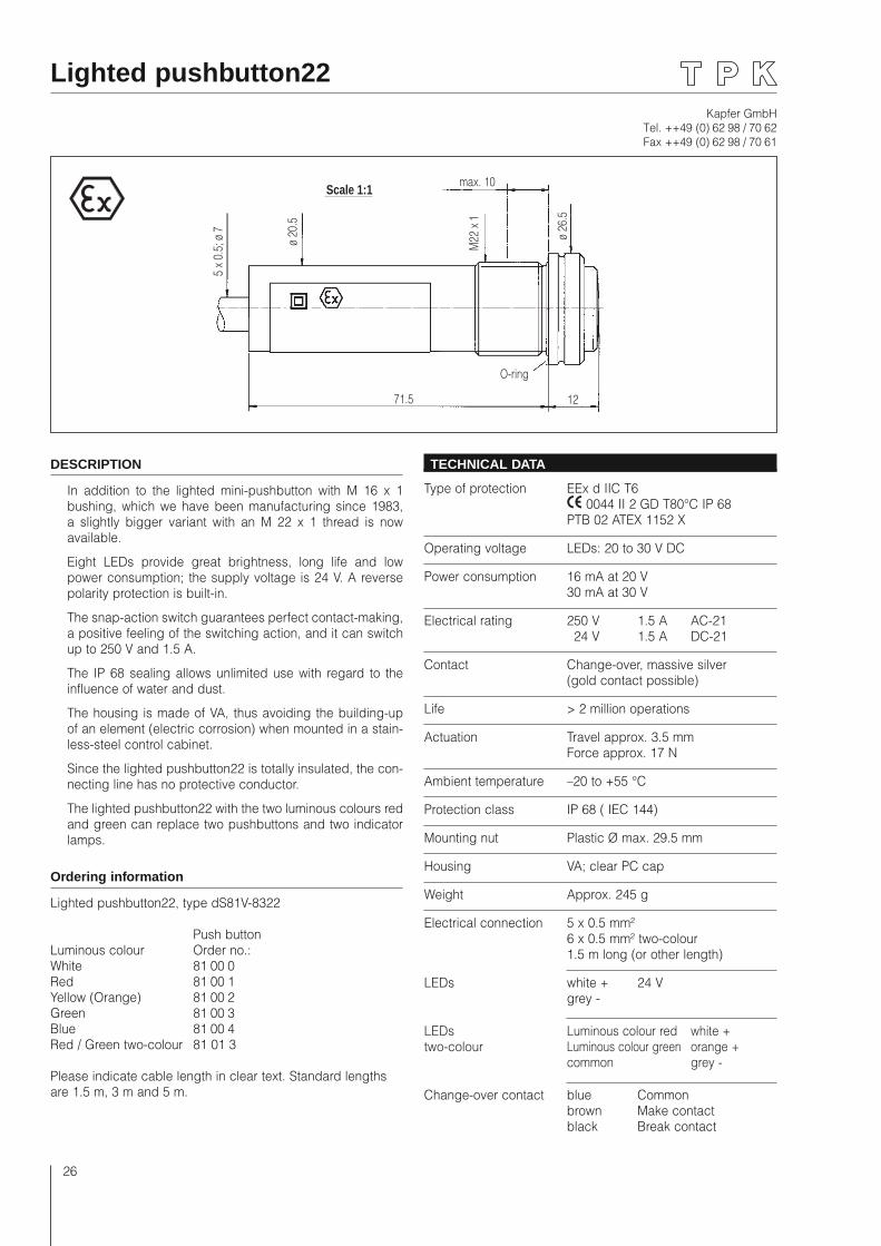
Lighted pushbutton22
Scale 1:1max. 10
5 x
0.5;
ø 7
ø 20
.5
ø 26
.5
M22
x 1
71.5 12
O-ring
DESCRIPTION
In addition to the lighted mini-pushbutton with M 16 x 1 bushing, which we have been manufacturing since 1983, a slightly bigger variant with an M 22 x 1 thread is now available.
Eight LEDs provide great brightness, long life and low power consumption; the supply voltage is 24 V. A reverse polarity protection is built-in.
The snap-action switch guarantees perfect contact-making, a positive feeling of the switching action, and it can switch up to 250 V and 1.5 A.
The IP 68 sealing allows unlimited use with regard to the influence of water and dust.
The housing is made of VA, thus avoiding the building-up of an element (electric corrosion) when mounted in a stain-less-steel control cabinet.
Since the lighted pushbutton22 is totally insulated, the con-necting line has no protective conductor.
The lighted pushbutton22 with the two luminous colours red and green can replace two pushbuttons and two indicator lamps.
Ordering information
Lighted pushbutton22, type dS81V-8322
Push buttonLuminous colour Order no.:White 81 00 0Red 81 00 1Yellow (Orange) 81 00 2Green 81 00 3Blue 81 00 4Red / Green two-colour 81 01 3
Please indicate cable length in clear text. Standard lengths are 1.5 m, 3 m and 5 m.
TECHNICAL DATA
Type of protection EEx d IIC T6 0044 II 2 GD T80°C IP 68 PTB 02 ATEX 1152 X
Operating voltage LEDs: 20 to 30 V DC
Power consumption 16 mA at 20 V 30 mA at 30 V
Electrical rating 250 V 1.5 A AC-21 24 V 1.5 A DC-21
Contact Change-over, massive silver (gold contact possible)
Life > 2 million operations
Actuation Travel approx. 3.5 mm Force approx. 17 N
Ambient temperature –20 to +55 °C
Protection class IP 68 ( IEC 144)
Mounting nut Plastic Ø max. 29.5 mm
Housing VA; clear PC cap
Weight Approx. 245 g
Electrical connection 5 x 0.5 mm² 6 x 0.5 mm² two-colour 1.5 m long (or other length)
LEDs white + 24 V grey -
LEDs Luminous colour red white + two-colour Luminous colour green orange + common grey -
Change-over contact blue Common brown Make contact black Break contact
Kapfer GmbHTel. ++49 (0) 62 98 / 70 62Fax ++49 (0) 62 98 / 70 61
27
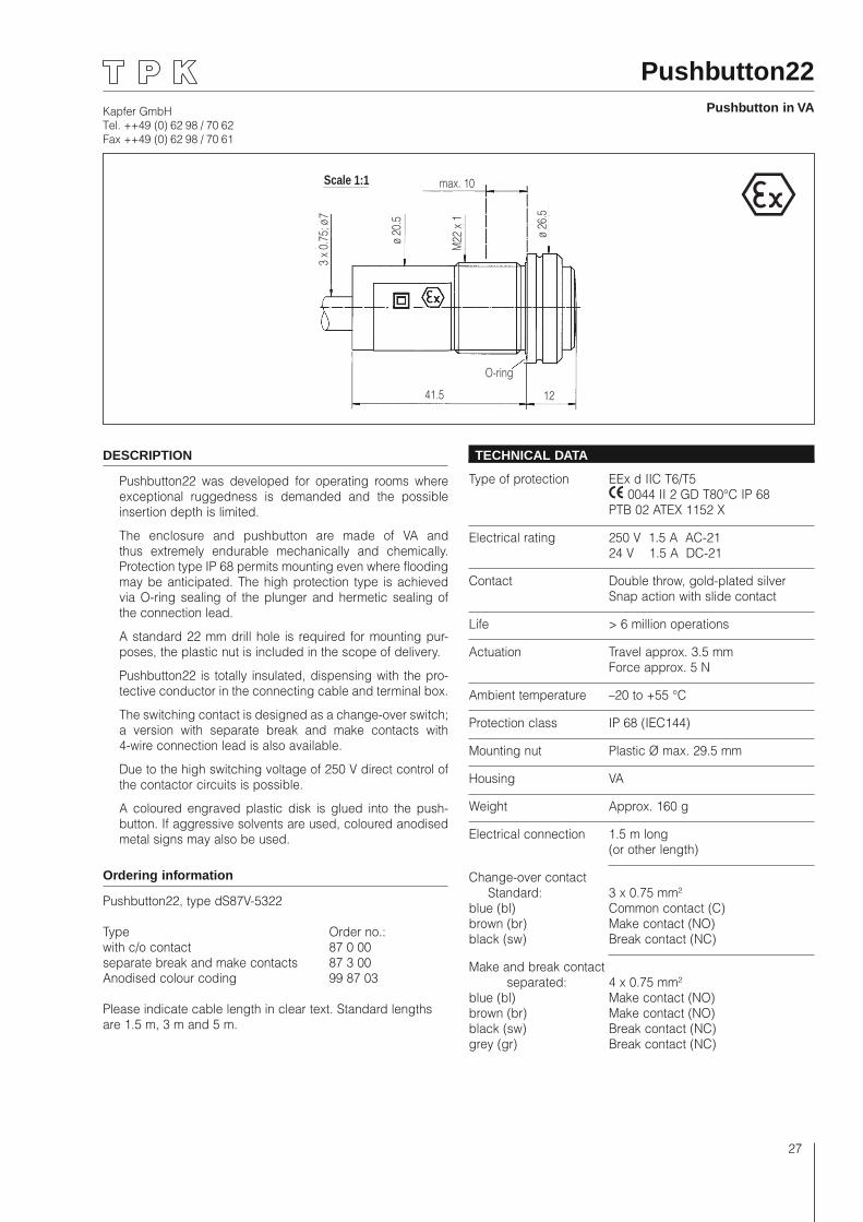
Pushbutton22Pushbutton in VA
Scale 1:1 max. 10
3 x
0.75
; ø 7
ø 20
.5
ø 26
.5
M22
x 1
41.5 12
O-ring
DESCRIPTION
Pushbutton22 was developed for operating rooms where exceptional ruggedness is demanded and the possible insertion depth is limited.
The enclosure and pushbutton are made of VA and thus extremely endurable mechanically and chemically. Protection type IP 68 permits mounting even where flooding may be anticipated. The high protection type is achieved via O-ring sealing of the plunger and hermetic sealing of the connection lead.
A standard 22 mm drill hole is required for mounting pur-poses, the plastic nut is included in the scope of delivery.
Pushbutton22 is totally insulated, dispensing with the pro-tective conductor in the connecting cable and terminal box.
The switching contact is designed as a change-over switch; a version with separate break and make contacts with 4-wire connection lead is also available.
Due to the high switching voltage of 250 V direct control of the contactor circuits is possible.
A coloured engraved plastic disk is glued into the push-button. If aggressive solvents are used, coloured anodised metal signs may also be used.
Ordering information
Pushbutton22, type dS87V-5322
Type Order no.:with c/o contact 87 0 00separate break and make contacts 87 3 00Anodised colour coding 99 87 03
Please indicate cable length in clear text. Standard lengths are 1.5 m, 3 m and 5 m.
TECHNICAL DATA
Type of protection EEx d IIC T6/T5 0044 II 2 GD T80°C IP 68 PTB 02 ATEX 1152 X
Electrical rating 250 V 1.5 A AC-21 24 V 1.5 A DC-21
Contact Double throw, gold-plated silver Snap action with slide contact
Life > 6 million operations
Actuation Travel approx. 3.5 mm Force approx. 5 N
Ambient temperature –20 to +55 °C
Protection class IP 68 (IEC144)
Mounting nut Plastic Ø max. 29.5 mm
Housing VA
Weight Approx. 160 g
Electrical connection 1.5 m long (or other length)
Change-over contact Standard: 3 x 0.75 mm²blue (bl) Common contact (C)brown (br) Make contact (NO)black (sw) Break contact (NC)
Make and break contact separated: 4 x 0.75 mm²blue (bl) Make contact (NO)brown (br) Make contact (NO)black (sw) Break contact (NC)grey (gr) Break contact (NC)
Kapfer GmbHTel. ++49 (0) 62 98 / 70 62Fax ++49 (0) 62 98 / 70 61
28
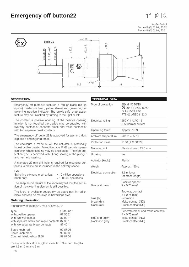
Emergency off button22
Scale 1:1max. 10
2 x
0.75
; ø 6
ø 20
.5 ø 29
.5
44.5 48O-ring
ø 28
3 x
0.75
; ø 6
.5
4 x
0.75
; ø 7
.5
M 2
2 x
1
DESCRIPTION
Emergency off button22 features a red or black (as an option) mushroom head, yellow sleeve and green ring as switching position indicator. The outwit safe snap action feature may be unlocked by turning to the right or left.
The contact is positive opening. If the positive opening function is not required the device may be supplied with two-way contact or separate break and make contact or with two separate break contacts.
The emergency off button22 is approved for gas and dust explosion-endangered areas.
The enclosure is made of VA, the actuator in practically indestructible plastic. Protection type IP 68 permits opera-tion even where flooding may be anticipated. The high pro-tection type is achieved with O-ring sealing of the plunger and hermetic sealing.
A standard 22 mm drill hole is required for mounting pur-poses, a plastic nut is included in the delivery scope.
Life: Switching element, mechanical: > 10 million operations Knob only: > 100 000 operations
The snap action feature of the knob may fail, but the actua-tion of the switching element is still possible.
The knob is available separately as spare part in red or black and can be mounted in hazardous area.
Ordering information
Emergency off button22, type dS87V-8722
Type Order no.: with positive opener 87 50 2with two-way contact 87 00 1with separate break and make contacts 87 30 1with two separate break contacts 87 40 1
Spare knob red 99 87 05Spare knob black 99 87 06Contrast label, yellow Ø 60 99 87 01
Please indicate cable length in clear text. Standard lengths are 1.5 m, 3 m and 5 m.
TECHNICAL DATA
Type of protection EEx d IIC T6/T5 0044 II 2 GD 80°C or T5 95°C IP68 PTB 02 ATEX 1152 X
Electrical rating 250 V 1 A AC 15 5 A thermal current
Operating force Approx. 16 N
Ambient temperature –20 to +55 °C
Protection class IP 68 (IEC 60529)
Mounting nut Plastic Ø max. 29.5 mm
Housing VA
Actuator (knob) Plastic
Weight Approx. 190 g
Electrical connection 1.5 m long (or other length)
Positive openerBlue and brown 2 x 0.75 mm²
Two-way contact 3 x 0.75 mm²blue (bl) - commonbrown (br) Make contact (NO)black (sw) Break contact (NC)
Seperate break and make contacts 4 x 0.75 mm²blue and brown Make contact (NO)black and grey Break contact (NC)
Kapfer GmbHTel. ++49 (0) 62 98 / 70 62Fax ++49 (0) 62 98 / 70 61
29
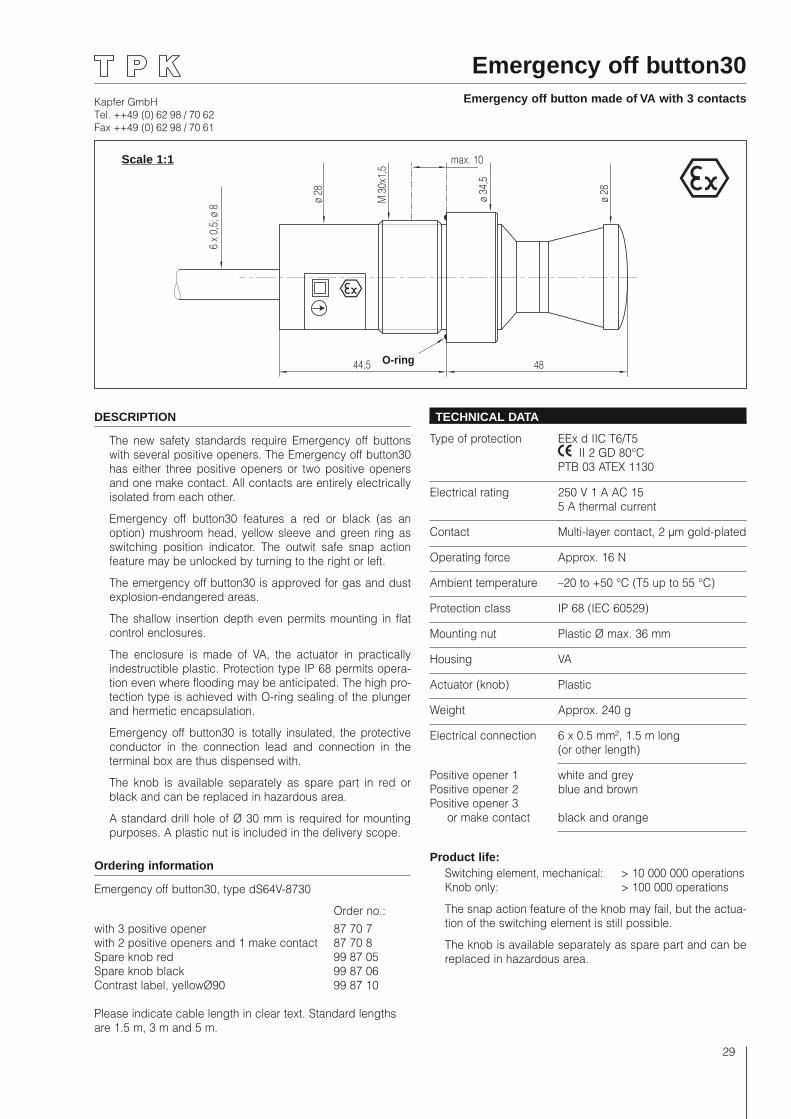
Emergency off button30Emergency off button made of VA with 3 contacts
DESCRIPTION
The new safety standards require Emergency off buttons with several positive openers. The Emergency off button30 has either three positive openers or two positive openers and one make contact. All contacts are entirely electrically isolated from each other.
Emergency off button30 features a red or black (as an option) mushroom head, yellow sleeve and green ring as switching position indicator. The outwit safe snap action feature may be unlocked by turning to the right or left.
The emergency off button30 is approved for gas and dust explosion-endangered areas.
The shallow insertion depth even permits mounting in flat control enclosures.
The enclosure is made of VA, the actuator in practically indestructible plastic. Protection type IP 68 permits opera-tion even where flooding may be anticipated. The high pro-tection type is achieved with O-ring sealing of the plunger and hermetic encapsulation.
Emergency off button30 is totally insulated, the protective conductor in the connection lead and connection in the terminal box are thus dispensed with.
The knob is available separately as spare part in red or black and can be replaced in hazardous area.
A standard drill hole of Ø 30 mm is required for mounting purposes. A plastic nut is included in the delivery scope.
Ordering information
Emergency off button30, type dS64V-8730
Order no.:with 3 positive opener 87 70 7with 2 positive openers and 1 make contact 87 70 8Spare knob red 99 87 05Spare knob black 99 87 06Contrast label, yellowØ90 99 87 10
Please indicate cable length in clear text. Standard lengths are 1.5 m, 3 m and 5 m.
TECHNICAL DATA
Type of protection EEx d IIC T6/T5 II 2 GD 80°C PTB 03 ATEX 1130
Electrical rating 250 V 1 A AC 15 5 A thermal current
Contact Multi-layer contact, 2 µm gold-plated
Operating force Approx. 16 N
Ambient temperature –20 to +50 °C (T5 up to 55 °C)
Protection class IP 68 (IEC 60529)
Mounting nut Plastic Ø max. 36 mm
Housing VA
Actuator (knob) Plastic
Weight Approx. 240 g
Electrical connection 6 x 0.5 mm², 1.5 m long (or other length)
Positive opener 1 white and grey Positive opener 2 blue and brown Positive opener 3 or make contact black and orange
Product life:
Switching element, mechanical: > 10 000 000 operations Knob only: > 100 000 operations
The snap action feature of the knob may fail, but the actua-tion of the switching element is still possible.
The knob is available separately as spare part and can be replaced in hazardous area.
max. 10
ø 28 ø 34
,5
44,5 48
ø 28
6 x
0,5;
ø 8
M 3
0x1,
5
Scale 1:1
O-ring
Kapfer GmbHTel. ++49 (0) 62 98 / 70 62Fax ++49 (0) 62 98 / 70 61
30
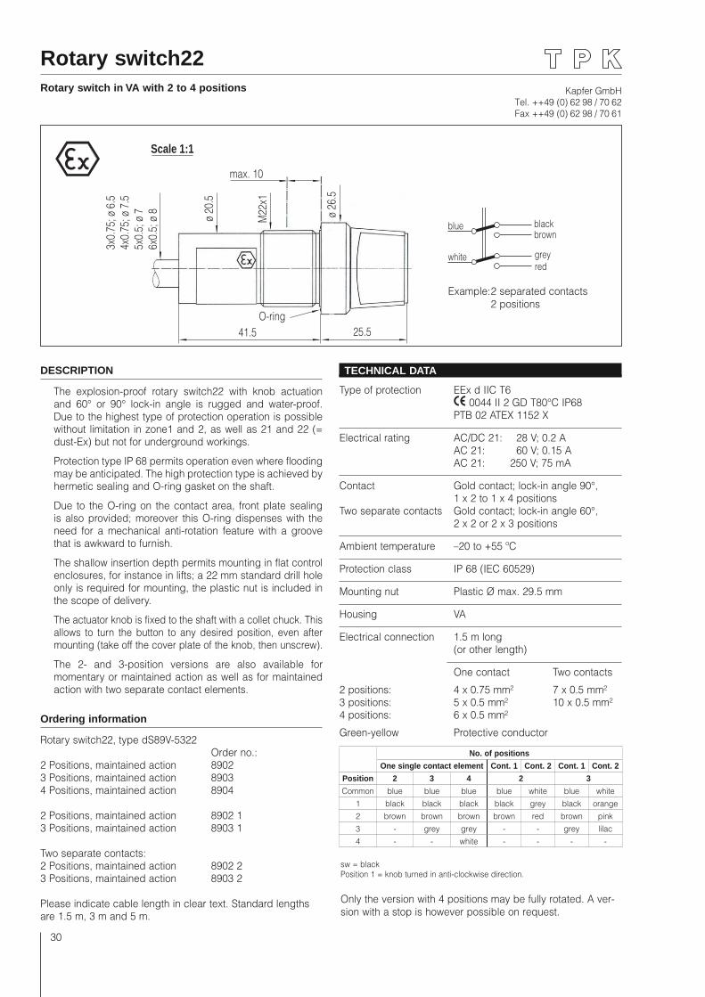
Rotary switch22Rotary switch in VA with 2 to 4 positions
Scale 1:1
max. 10
41.5 25.5
3x0.
75; ø
6.5
4x0.
75; ø
7.5
5x0.
5; ø
76x
0.5;
ø 8 ø 20
.5
M22
x1
ø 26
.5O-ring
DESCRIPTION
The explosion-proof rotary switch22 with knob actuation and 60° or 90° lock-in angle is rugged and water-proof. Due to the highest type of protection operation is possible without limitation in zone1 and 2, as well as 21 and 22 (= dust-Ex) but not for underground workings.
Protection type IP 68 permits operation even where flooding may be anticipated. The high protection type is achieved by hermetic sealing and O-ring gasket on the shaft.
Due to the O-ring on the contact area, front plate sealing is also provided; moreover this O-ring dispenses with the need for a mechanical anti-rotation feature with a groove that is awkward to furnish.
The shallow insertion depth permits mounting in flat control enclosures, for instance in lifts; a 22 mm standard drill hole only is required for mounting, the plastic nut is included in the scope of delivery.
The actuator knob is fixed to the shaft with a collet chuck. This allows to turn the button to any desired position, even after mounting (take off the cover plate of the knob, then unscrew).
The 2- and 3-position versions are also available for momentary or maintained action as well as for maintained action with two separate contact elements.
Ordering information
Rotary switch22, type dS89V-5322 Order no.:2 Positions, maintained action 89023 Positions, maintained action 89034 Positions, maintained action 8904
2 Positions, maintained action 8902 13 Positions, maintained action 8903 1
Two separate contacts:2 Positions, maintained action 8902 23 Positions, maintained action 8903 2
Please indicate cable length in clear text. Standard lengths are 1.5 m, 3 m and 5 m.
TECHNICAL DATA
Type of protection EEx d IIC T6 0044 II 2 GD T80°C IP68 PTB 02 ATEX 1152 X
Electrical rating AC/DC 21: 28 V; 0.2 A AC 21: 60 V; 0.15 A AC 21: 250 V; 75 mA
Contact Gold contact; lock-in angle 90°, 1 x 2 to 1 x 4 positionsTwo separate contacts Gold contact; lock-in angle 60°, 2 x 2 or 2 x 3 positions
Ambient temperature –20 to +55 ºC
Protection class IP 68 (IEC 60529)
Mounting nut Plastic Ø max. 29.5 mm
Housing VA
Electrical connection 1.5 m long (or other length)
One contact Two contacts
2 positions: 4 x 0.75 mm² 7 x 0.5 mm² 3 positions: 5 x 0.5 mm² 10 x 0.5 mm² 4 positions: 6 x 0.5 mm²
Green-yellow Protective conductor
sw = blackPosition 1 = knob turned in anti-clockwise direction.
Only the version with 4 positions may be fully rotated. A ver-sion with a stop is however possible on request.
blue
whiteredgrey
brownblack
Example: 2 separated contacts 2 positions
No. of positions
One single contact element Cont. 1 Cont. 2 Cont. 1 Cont. 2
Position 2 3 4 2 3
Common blue blue blue blue white blue white1 black black black black grey black orange2 brown brown brown brown red brown pink3 - grey grey - - grey lilac4 - - white - - - -
Kapfer GmbHTel. ++49 (0) 62 98 / 70 62Fax ++49 (0) 62 98 / 70 61
31
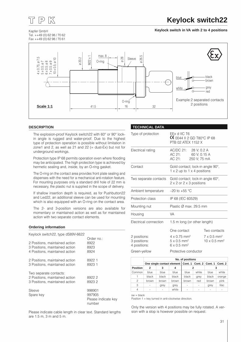
Keylock switch22Keylock switch in VA with 2 to 4 positions
ø 20
.2
M22
x 1
4 x
0.75
; ø 7
.55
x 0.
5; ø
76
x 0.
5; ø
87
x 0.
5; ø
910
x 0
.5; ø
10
ø 28
ø 26
.5
41.5 16 32
max. 8
O-ringSleeve
O-ring
DESCRIPTION
The explosion-proof Keylock switch22 with 60° or 90° lock-in angle is rugged and water-proof. Due to the highest type of protection operation is possible without limitation in zone1 and 2, as well as 21 and 22 (= dust-Ex) but not for underground workings.
Protection type IP 68 permits operation even where flooding may be anticipated. The high protection type is achieved by hermetic sealing and, inside, by an O-ring gasket.
The O-ring on the contact area provides front plate sealing and dispenses with the need for a mechanical anti-rotation feature. For mounting purposes only a standard drill hole of 22 mm is necessary, the plastic nut is supplied in the scope of delivery.
If shallow insertion depth is required, as for Pushbutton22 and Led22, an additional sleeve can be used for mounting which is also equipped with an O-ring on the contact area.
The 2- and 3-position versions are also available for momentary or maintained action as well as for maintained action with two separate contact elements.
Ordering information
Keylock switch22, type dS89V-6622 Order no.:2 Positions, maintained action 89223 Positions, maintained action 89234 Positions, maintained action 8924
2 Positions, maintained action 8922 13 Positions, maintained action 8923 1
Two separate contacts:2 Positions, maintained action 8922 23 Positions, maintained action 8923 2
Sleeve 998901Spare key 997905 Please indicate key number Please indicate cable length in clear text. Standard lengths are 1.5 m, 3 m and 5 m.
TECHNICAL DATA
Type of protection EEx d IIC T6 0044 II 2 GD T80°C IP 68 PTB 02 ATEX 1152 X
Electrical rating AC/DC 21: 28 V; 0.2 A AC 21: 60 V; 0.15 A AC 21: 250 V; 75 mA
Contact Gold contact; lock-in angle 90°, 1 x 2 up to 1 x 4 positions
Two separate contacts Gold contact; lock-in angle 60°, 2 x 2 or 2 x 3 positions
Ambient temperature –20 to +55 °C
Protection class IP 68 (IEC 60529)
Mounting nut Plastic Ø max. 29.5 mm
Housing VA
Electrical connection 1.5 m long (or other length)
One contact Two contacts
2 positions: 4 x 0.75 mm² 7 x 0.5 mm²3 positions: 5 x 0.5 mm² 10 x 0.5 mm²4 positions: 6 x 0.5 mm²
Green-yellow Protective conductor
sw = blackPosition 1 = key turned in anti-clockwise direction.
Only the version with 4 positions may be fully rotated. A ver-sion with a stop is however possible on request.
Scale 1:1
No. of positions
One single contact element Cont. 1 Cont. 2 Cont. 1 Cont. 2
Position 2 3 4 2 3
Common blue blue blue blue white blue white1 black black black black grey black orange2 brown brown brown brown red brown pink3 - grey grey - - grey lilac4 - - white - - - -
blue
whiteredgrey
brownblack
Example: 2 separated contacts 2 positions
Kapfer GmbHTel. ++49 (0) 62 98 / 70 62Fax ++49 (0) 62 98 / 70 61
32
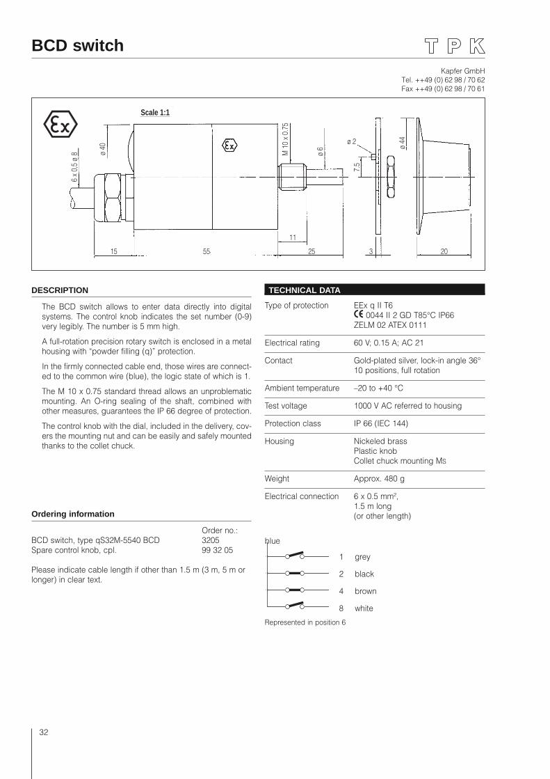
DESCRIPTION
The BCD switch allows to enter data directly into digital systems. The control knob indicates the set number (0-9) very legibly. The number is 5 mm high.
A full-rotation precision rotary switch is enclosed in a metal housing with “powder filling (q)” protection.
In the firmly connected cable end, those wires are connect-ed to the common wire (blue), the logic state of which is 1.
The M 10 x 0.75 standard thread allows an unproblematic mounting. An O-ring sealing of the shaft, combined with other measures, guarantees the IP 66 degree of protection.
The control knob with the dial, included in the delivery, cov-ers the mounting nut and can be easily and safely mounted thanks to the collet chuck.
Ordering information
Order no.:BCD switch, type qS32M-5540 BCD 3205Spare control knob, cpl. 99 32 05
Please indicate cable length if other than 1.5 m (3 m, 5 m or longer) in clear text.
TECHNICAL DATA
Type of protection EEx q II T6 0044 II 2 GD T85°C IP66 ZELM 02 ATEX 0111
Electrical rating 60 V; 0.15 A; AC 21
Contact Gold-plated silver, lock-in angle 36° 10 positions, full rotation
Ambient temperature –20 to +40 °C
Test voltage 1000 V AC referred to housing
Protection class IP 66 (IEC 144)
Housing Nickeled brass Plastic knob Collet chuck mounting MS
Weight Approx. 480 g
Electrical connection 6 x 0.5 mm², 1.5 m long (or other length)
blue
BCD switch
15 55 25
11
3 20
ø 2
7.5
ø 44
ø 6
M 1
0 x
0.75
Scale 1:1ø
40
6 x
0,5
ø 8
Represented in position 6
1 grey
2 black
4 brown
8 white
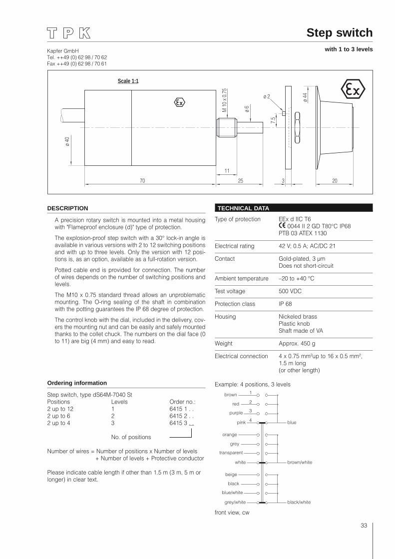
Kapfer GmbHTel. ++49 (0) 62 98 / 70 62Fax ++49 (0) 62 98 / 70 61
33
Step switchwith 1 to 3 levels
70 25
11
3 20
ø 2
7.5
ø 44
ø 6
M 1
0 x
0.75
Scale 1:1
ø 40
DESCRIPTION
A precision rotary switch is mounted into a metal housing with "Flameproof enclosure (d)" type of protection.
The explosion-proof step switch with a 30° lock-in angle is available in various versions with 2 to 12 switching positions and with up to three levels. Only the version with 12 posi-tions is, as an option, available as a full-rotation version.
Potted cable end is provided for connection. The number of wires depends on the number of switching positions and levels.
The M10 x 0.75 standard thread allows an unproblematic mounting. The O-ring sealing of the shaft in combination with the potting guarantees the IP 68 degree of protection.
The control knob with the dial, included in the delivery, cov-ers the mounting nut and can be easily and safely mounted thanks to the collet chuck. The numbers on the dial face (0 to 11) are big (4 mm) and easy to read.
Ordering information
Step switch, type dS64M-7040 StPositions Levels Order no.:2 up to 12 1 6415 1 . .2 up to 6 2 6415 2 . . 2 up to 4 3 6415 3 . .
No. of positions
Number of wires = Number of positions x Number of levels + Number of levels + Protective conductor
Please indicate cable length if other than 1.5 m (3 m, 5 m or longer) in clear text.
TECHNICAL DATA
Type of protection EEx d IIC T6 0044 II 2 GD T80°C IP68 PTB 03 ATEX 1130
Electrical rating 42 V; 0.5 A; AC/DC 21
Contact Gold-plated, 3 µm Does not short-circuit
Ambient temperature –20 to +40 °C
Test voltage 500 VDC
Protection class IP 68
Housing Nickeled brass Plastic knob Shaft made of VA
Weight Approx. 450 g
Electrical connection 4 x 0.75 mm²up to 16 x 0.5 mm², 1.5 m long (or other length)
Example: 4 positions, 3 levels
brown
red
purple
pink blue
1
4
3
2
orange
grey
transparent
white brown/white
beige
black
blue/white
grey/white black/white
front view, cw
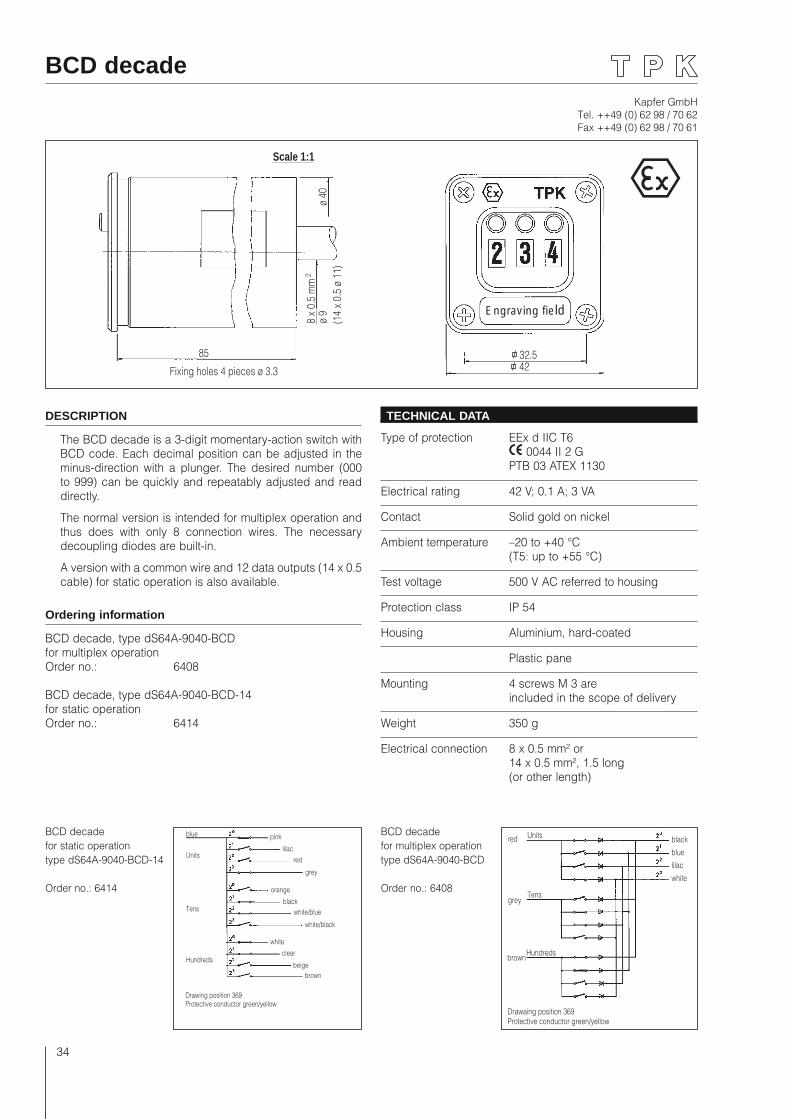
Kapfer GmbHTel. ++49 (0) 62 98 / 70 62Fax ++49 (0) 62 98 / 70 61
34
BCD decade
85
Fixing holes 4 pieces ø 3.3
8 x
0.5
mm
2
ø 9
ø 40
(14
x 0.
5 ø
11)
Scale 1:1
32.542
Engraving field
BCD decade for static operation type dS64A-9040-BCD-14
Order no.: 6414
Drawing position 369Protective conductor green/yellow
blue
Units
Tens
Hundreds
pink
lilacred
grey
orange
blackwhite/blue
white/black
whiteclear
beigebrown
BCD decade for multiplex operation type dS64A-9040-BCD
Order no.: 6408
Drawaing position 369Protective conductor green/yellow
Units
Tens
Hundreds
red
grey
white
brown
lilac
blue
black
DESCRIPTION
The BCD decade is a 3-digit momentary-action switch with BCD code. Each decimal position can be adjusted in the minus-direction with a plunger. The desired number (000 to 999) can be quickly and repeatably adjusted and read directly.
The normal version is intended for multiplex operation and thus does with only 8 connection wires. The necessary decoupling diodes are built-in.
A version with a common wire and 12 data outputs (14 x 0.5 cable) for static operation is also available.
Ordering information
BCD decade, type dS64A-9040-BCDfor multiplex operationOrder no.: 6408
BCD decade, type dS64A-9040-BCD-14for static operationOrder no.: 6414
TECHNICAL DATA
Type of protection EEx d IIC T6 0044 II 2 G PTB 03 ATEX 1130
Electrical rating 42 V; 0.1 A; 3 VA
Contact Solid gold on nickel
Ambient temperature –20 to +40 °C (T5: up to +55 °C)
Test voltage 500 V AC referred to housing
Protection class IP 54
Housing Aluminium, hard-coated
Plastic pane
Mounting 4 screws M 3 are included in the scope of delivery
Weight 350 g
Electrical connection 8 x 0.5 mm² or 14 x 0.5 mm², 1.5 long (or other length)
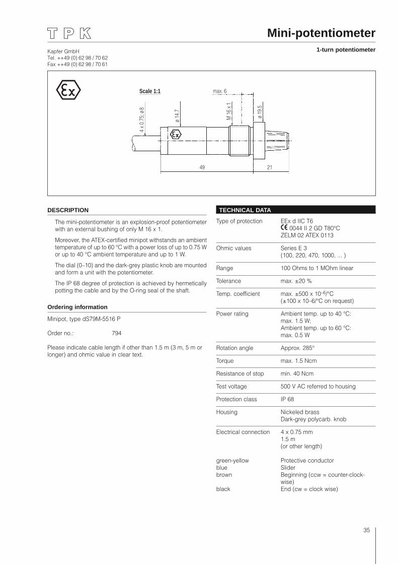
Kapfer GmbHTel. ++49 (0) 62 98 / 70 62Fax ++49 (0) 62 98 / 70 61
35
49 21
ø 19
.5
M 1
6 x 1
max. 6
ø 14
.7
4 x
0.75
; ø 8
Scale 1:1
Mini-potentiometer1-turn potentiometer
DESCRIPTION
The mini-potentiometer is an explosion-proof potentiometer with an external bushing of only M 16 x 1.
Moreover, the ATEX-certified minipot withstands an ambient temperature of up to 60 °C with a power loss of up to 0.75 W or up to 40 °C ambient temperature and up to 1 W.
The dial (0–10) and the dark-grey plastic knob are mounted and form a unit with the potentiometer.
The IP 68 degree of protection is achieved by hermetically potting the cable and by the O-ring seal of the shaft.
Ordering information
Minipot, type dS79M-5516 P
Order no.: 794
Please indicate cable length if other than 1.5 m (3 m, 5 m or longer) and ohmic value in clear text.
TECHNICAL DATA
Type of protection EEx d IIC T6 0044 II 2 GD T80°C ZELM 02 ATEX 0113
Ohmic values Series E 3 (100, 220, 470, 1000, ... )
Range 100 Ohms to 1 MOhm linear
Tolerance max. ±20 %
Temp. coefficient max. ±500 x 10–6/°C (±100 x 10–6/°C on request)
Power rating Ambient temp. up to 40 °C: max. 1.5 W; Ambient temp. up to 60 °C: max. 0.5 W
Rotation angle Approx. 285°
Torque max. 1.5 Ncm
Resistance of stop min. 40 Ncm
Test voltage 500 V AC referred to housing
Protection class IP 68
Housing Nickeled brass Dark-grey polycarb. knob
Electrical connection 4 x 0.75 mm 1.5 m (or other length)
green-yellow Protective conductorblue Sliderbrown Beginning (ccw = counter-clock-
wise)black End (cw = clock wise)
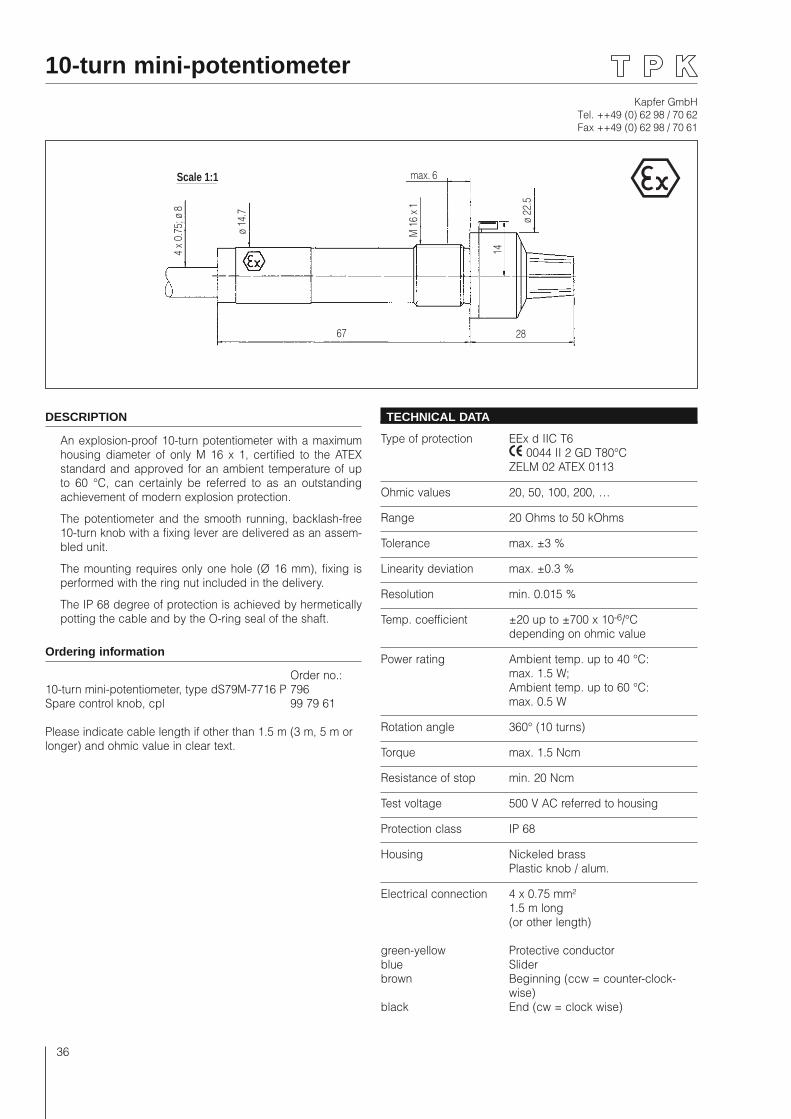
Kapfer GmbHTel. ++49 (0) 62 98 / 70 62Fax ++49 (0) 62 98 / 70 61
36
10-turn mini-potentiometer
67 28
ø 22
.5
M 1
6 x 1
max. 6
ø 14
.7
4 x
0.75
; ø 8
Scale 1:1
14
DESCRIPTION
An explosion-proof 10-turn potentiometer with a maximum housing diameter of only M 16 x 1, certified to the ATEX standard and approved for an ambient temperature of up to 60 °C, can certainly be referred to as an outstanding achievement of modern explosion protection.
The potentiometer and the smooth running, backlash-free 10-turn knob with a fixing lever are delivered as an assem-bled unit.
The mounting requires only one hole (Ø 16 mm), fixing is performed with the ring nut included in the delivery.
The IP 68 degree of protection is achieved by hermetically potting the cable and by the O-ring seal of the shaft.
Ordering information
Order no.:10-turn mini-potentiometer, type dS79M-7716 P 796Spare control knob, cpl 99 79 61
Please indicate cable length if other than 1.5 m (3 m, 5 m or longer) and ohmic value in clear text.
TECHNICAL DATA
Type of protection EEx d IIC T6 0044 II 2 GD T80°C ZELM 02 ATEX 0113
Ohmic values 20, 50, 100, 200, …
Range 20 Ohms to 50 kOhms
Tolerance max. ±3 %
Linearity deviation max. ±0.3 %
Resolution min. 0.015 %
Temp. coefficient ±20 up to ±700 x 10-6/°C depending on ohmic value
Power rating Ambient temp. up to 40 °C: max. 1.5 W; Ambient temp. up to 60 °C: max. 0.5 W
Rotation angle 360° (10 turns)
Torque max. 1.5 Ncm
Resistance of stop min. 20 Ncm
Test voltage 500 V AC referred to housing
Protection class IP 68
Housing Nickeled brass Plastic knob / alum.
Electrical connection 4 x 0.75 mm² 1.5 m long (or other length)
green-yellow Protective conductorblue Sliderbrown Beginning (ccw = counter-clock-
wise)black End (cw = clock wise)
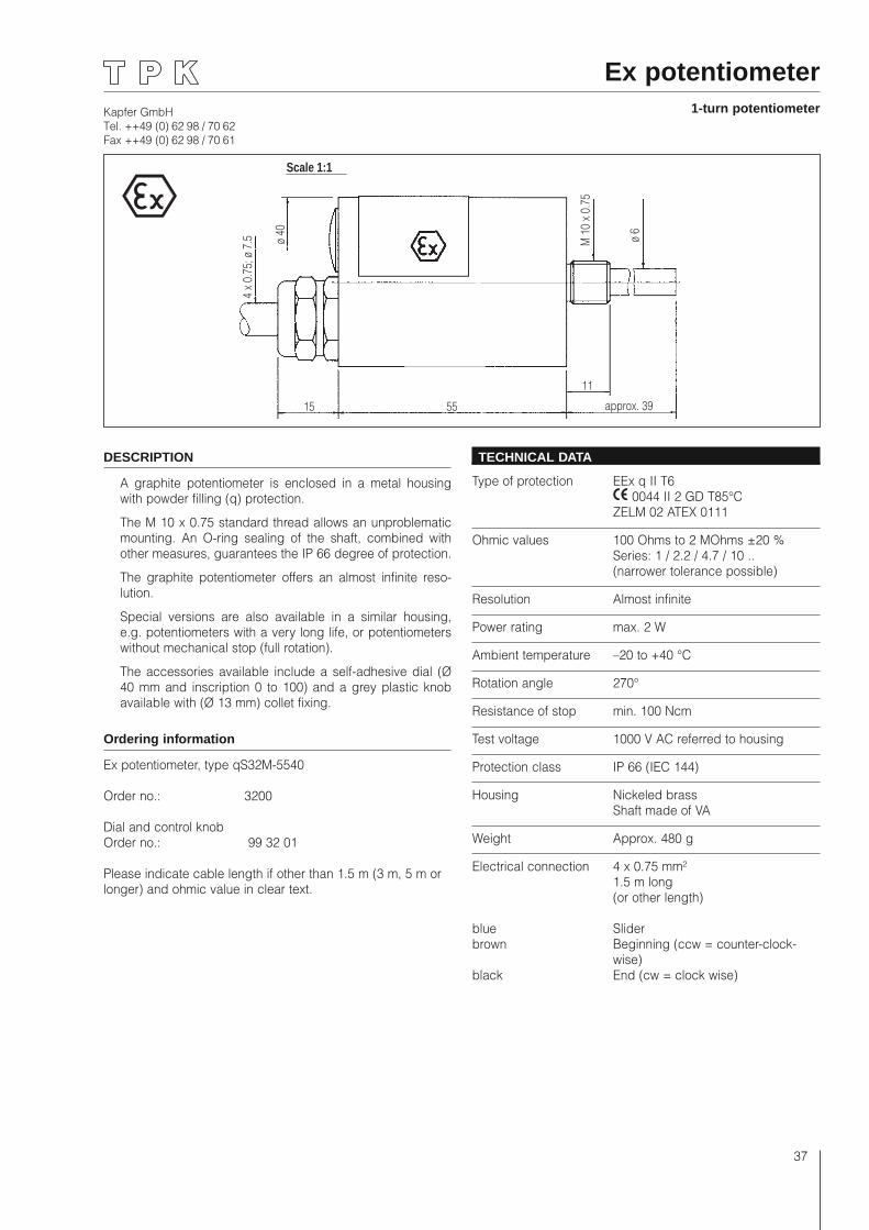
Kapfer GmbHTel. ++49 (0) 62 98 / 70 62Fax ++49 (0) 62 98 / 70 61
37
15 approx. 39
4 x
0.75
; ø 7
.5
Scale 1:1
55
11
ø 40
M 1
0 x
0.75
ø 6
Ex potentiometer1-turn potentiometer
DESCRIPTION
A graphite potentiometer is enclosed in a metal housing with powder filling (q) protection.
The M 10 x 0.75 standard thread allows an unproblematic mounting. An O-ring sealing of the shaft, combined with other measures, guarantees the IP 66 degree of protection.
The graphite potentiometer offers an almost infinite reso-lution.
Special versions are also available in a similar housing, e.g. potentiometers with a very long life, or potentiometers without mechanical stop (full rotation).
The accessories available include a self-adhesive dial (Ø 40 mm and inscription 0 to 100) and a grey plastic knob available with (Ø 13 mm) collet fixing.
Ordering information
Ex potentiometer, type qS32M-5540
Order no.: 3200
Dial and control knobOrder no.: 99 32 01
Please indicate cable length if other than 1.5 m (3 m, 5 m or longer) and ohmic value in clear text.
TECHNICAL DATA
Type of protection EEx q II T6 0044 II 2 GD T85°C ZELM 02 ATEX 0111
Ohmic values 100 Ohms to 2 MOhms ±20 % Series: 1 / 2.2 / 4.7 / 10 .. (narrower tolerance possible)
Resolution Almost infinite
Power rating max. 2 W
Ambient temperature –20 to +40 °C
Rotation angle 270°
Resistance of stop min. 100 Ncm
Test voltage 1000 V AC referred to housing
Protection class IP 66 (IEC 144)
Housing Nickeled brass Shaft made of VA
Weight Approx. 480 g
Electrical connection 4 x 0.75 mm² 1.5 m long (or other length)
blue Sliderbrown Beginning (ccw = counter-clock-
wise)black End (cw = clock wise)
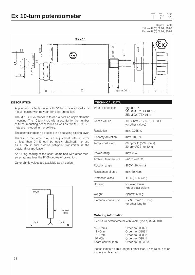
Kapfer GmbHTel. ++49 (0) 62 98 / 70 62Fax ++49 (0) 62 98 / 70 61
38
DESCRIPTION
A precision potentiometer with 10 turns is enclosed in a metal housing with powder filling (q) protection.
The M 10 x 0.75 standard thread allows an unproblematic mounting. The 10-turn knob with a counter for the number of turns, mounting accessories as well as two M 10 x 0.75 nuts are included in the delivery.
The control knob can be locked in place using a fixing lever.
Thanks to the large dial, an adjustment with an error of less than 0.1 % can be easily obtained; the use as a robust and precise set-point transmitter is the outstanding application.
An O-ring sealing of the shaft, combined with other mea-sures, guarantees the IP 68 degree of protection.
Other ohmic values are available as an option.
TECHNICAL DATA
Type of protection EEx q II T6 0044 II 2 GD T85°C ZELM 02 ATEX 0111
Ohmic values 100 Ohms / 1 / 5 / 10 k ±3 % (or other values)
Resolution min. 0.055 %
Linearity deviation max. ±0.2 %
Temp. coefficient 80 ppm/°C (100 Ohms) 20 ppm/°C (1 to 10 k)
Power rating max. 3 W
Ambient temperature –20 to +40 °C
Rotation angle 3600° (10 turns)
Resistance of stop min. 80 Ncm
Protection class IP 66 (EN 60529)
Housing Nickeled brass Knob: plastic/alum.
Weight Approx. 550 g
Electrical connection 5 x 0.5 mm², 1.5 long (or other length)
Ordering information
Ex-10-turn potentiometer with knob, type qS32M-6040
100 Ohms Order no.: 32021 1 kOhm Order no.: 32031 5 kOhm Order no.: 32032 10 kOhm Order no.: 32041Spare control knob Order no.: 99 32 02
Please indicate cable length if other than 1.5 m (3 m, 5 m or longer) in clear text.
Ex 10-turn potentiometer
15
Scale 1:1
60
ø 40
M10
x 0
.75
ø 46
5 x
0.5
mm
2
10
2.5
ø 6.
35
11
approx. 26 26
ø 9
brown
black
blue
black
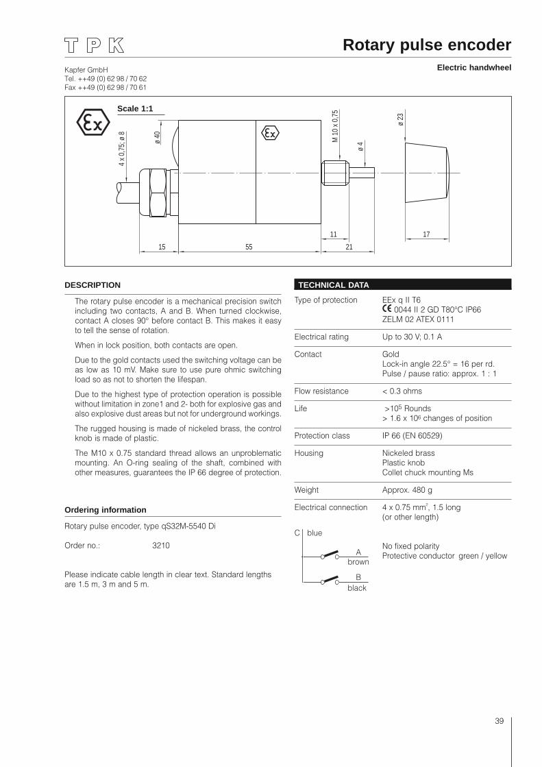
Kapfer GmbHTel. ++49 (0) 62 98 / 70 62Fax ++49 (0) 62 98 / 70 61
39
55 211511 17
ø 4
4 x 0
,75;
ø 8
M 1
0 x 0
,75
ø 23
ø 40
Rotary pulse encoderElectric handwheel
DESCRIPTION
The rotary pulse encoder is a mechanical precision switch including two contacts, A and B. When turned clockwise, contact A closes 90° before contact B. This makes it easy to tell the sense of rotation.
When in lock position, both contacts are open.
Due to the gold contacts used the switching voltage can be as low as 10 mV. Make sure to use pure ohmic switching load so as not to shorten the lifespan.
Due to the highest type of protection operation is possible without limitation in zone1 and 2- both for explosive gas and also explosive dust areas but not for underground workings.
The rugged housing is made of nickeled brass, the control knob is made of plastic.
The M10 x 0.75 standard thread allows an unproblematic mounting. An O-ring sealing of the shaft, combined with other measures, guarantees the IP 66 degree of protection.
Ordering information
Rotary pulse encoder, type qS32M-5540 Di
Order no.: 3210
Please indicate cable length in clear text. Standard lengths are 1.5 m, 3 m and 5 m.
TECHNICAL DATA
Type of protection EEx q II T6 0044 II 2 GD T80°C IP66 ZELM 02 ATEX 0111
Electrical rating Up to 30 V; 0.1 A
Contact Gold Lock-in angle 22.5° = 16 per rd. Pulse / pause ratio: approx. 1 : 1
Flow resistance < 0.3 ohms
Life >105 Rounds > 1.6 x 10⁶ changes of position
Protection class IP 66 (EN 60529)
Housing Nickeled brass Plastic knob Collet chuck mounting Ms
Weight Approx. 480 g
Electrical connection 4 x 0.75 mm², 1.5 long (or other length)
No fixed polarity Protective conductor green / yellowA
brown
B black
C blue
Scale 1:1
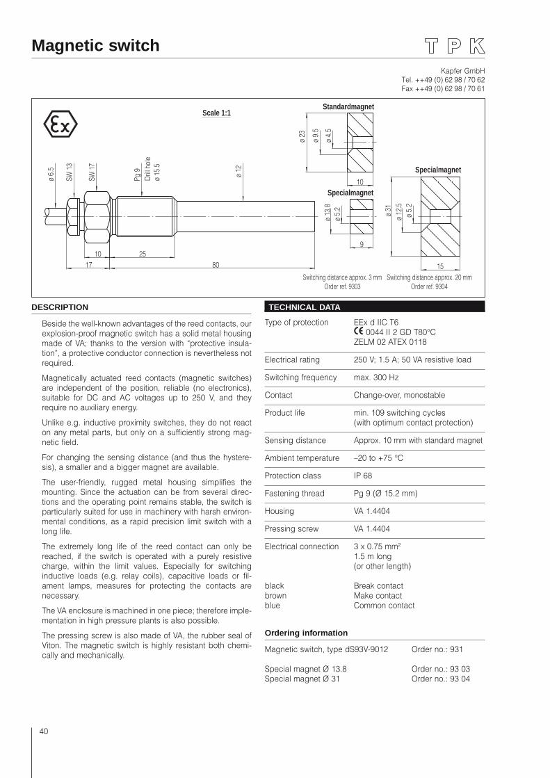
Kapfer GmbHTel. ++49 (0) 62 98 / 70 62Fax ++49 (0) 62 98 / 70 61
40
Magnetic switch
80172510
ø 12
Pg 9
SW 1
7
SW 1
3
ø 6.
5
ø 31
ø 12
.5ø
5.2
15
ø 13
.8ø
5.2
9
Specialmagnet
Switching distance approx. 20 mmOrder ref. 9304
Switching distance approx. 3 mmOrder ref. 9303
Scale 1:1
ø 23
ø 9.
5
ø 4.
5
10
Standardmagnet
Specialmagnet
Drill
hole
ø 15
.5
DESCRIPTION
Beside the well-known advantages of the reed contacts, our explosion-proof magnetic switch has a solid metal housing made of VA; thanks to the version with “protective insula-tion”, a protective conductor connection is nevertheless not required.
Magnetically actuated reed contacts (magnetic switches) are independent of the position, reliable (no electronics), suitable for DC and AC voltages up to 250 V, and they require no auxiliary energy.
Unlike e.g. inductive proximity switches, they do not react on any metal parts, but only on a sufficiently strong mag-netic field.
For changing the sensing distance (and thus the hystere-sis), a smaller and a bigger magnet are available.
The user-friendly, rugged metal housing simplifies the mounting. Since the actuation can be from several direc-tions and the operating point remains stable, the switch is particularly suited for use in machinery with harsh environ-mental conditions, as a rapid precision limit switch with a long life.
The extremely long life of the reed contact can only be reached, if the switch is operated with a purely resistive charge, within the limit values. Especially for switching inductive loads (e.g. relay coils), capacitive loads or fil-ament lamps, measures for protecting the contacts are necessary.
The VA enclosure is machined in one piece; therefore imple-mentation in high pressure plants is also possible.
The pressing screw is also made of VA, the rubber seal of Viton. The magnetic switch is highly resistant both chemi-cally and mechanically.
TECHNICAL DATA
Type of protection EEx d IIC T6 0044 II 2 GD T80°C ZELM 02 ATEX 0118
Electrical rating 250 V; 1.5 A; 50 VA resistive load
Switching frequency max. 300 Hz
Contact Change-over, monostable
Product life min. 109 switching cycles (with optimum contact protection)
Sensing distance Approx. 10 mm with standard magnet
Ambient temperature –20 to +75 °C
Protection class IP 68
Fastening thread Pg 9 (Ø 15.2 mm)
Housing VA 1.4404
Pressing screw VA 1.4404
Electrical connection 3 x 0.75 mm² 1.5 m long (or other length)
black Break contactbrown Make contactblue Common contact
Ordering information
Magnetic switch, type dS93V-9012 Order no.: 931
Special magnet Ø 13.8 Order no.: 93 03Special magnet Ø 31 Order no.: 93 04
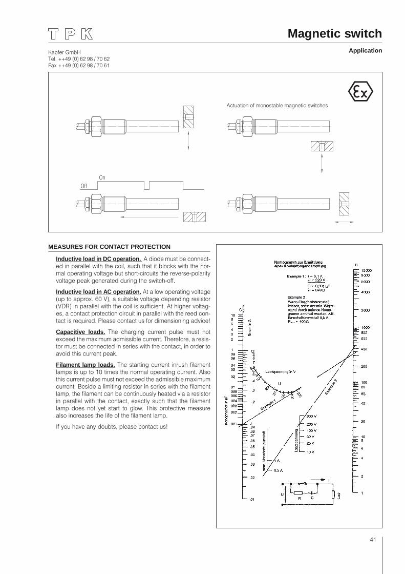
Kapfer GmbHTel. ++49 (0) 62 98 / 70 62Fax ++49 (0) 62 98 / 70 61
41
MEASURES FOR CONTACT PROTECTION
Inductive load in DC operation. A diode must be connect-ed in parallel with the coil, such that it blocks with the nor-mal operating voltage but short-circuits the reverse-polarity voltage peak generated during the switch-off.
Inductive load in AC operation. At a low operating voltage (up to approx. 60 V), a suitable voltage depending resistor (VDR) in parallel with the coil is sufficient. At higher voltag-es, a contact protection circuit in parallel with the reed con-tact is required. Please contact us for dimensioning advice!
Capacitive loads. The charging current pulse must not exceed the maximum admissible current. Therefore, a resis-tor must be connected in series with the contact, in order to avoid this current peak.
Filament lamp loads. The starting current inrush filament lamps is up to 10 times the normal operating current. Also this current pulse must not exceed the admissible maximum current. Beside a limiting resistor in series with the filament lamp, the filament can be continuously heated via a resistor in parallel with the contact, exactly such that the filament lamp does not yet start to glow. This protective measure also increases the life of the filament lamp.
If you have any doubts, please contact us!
Magnetic switchApplication
OnOff
Actuation of monostable magnetic switches
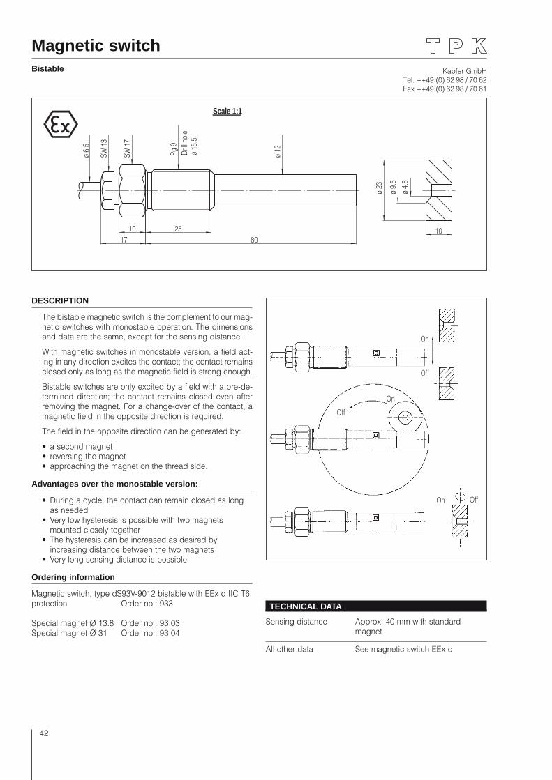
Kapfer GmbHTel. ++49 (0) 62 98 / 70 62Fax ++49 (0) 62 98 / 70 61
42
Magnetic switchBistable
ø 23
ø 9.
5ø
4.5
108017
2510
ø 12Pg
9
SW 1
7
SW 1
3
ø 6.
5
Scale 1:1
Drill
hole
ø 15
.5
On
Off
On
On Off
Off
DESCRIPTION
The bistable magnetic switch is the complement to our mag-netic switches with monostable operation. The dimensions and data are the same, except for the sensing distance.
With magnetic switches in monostable version, a field act-ing in any direction excites the contact; the contact remains closed only as long as the magnetic field is strong enough.
Bistable switches are only excited by a field with a pre-de-termined direction; the contact remains closed even after removing the magnet. For a change-over of the contact, a magnetic field in the opposite direction is required.
The field in the opposite direction can be generated by:
• a second magnet• reversing the magnet• approaching the magnet on the thread side.
Advantages over the monostable version:
• During a cycle, the contact can remain closed as long as needed
• Very low hysteresis is possible with two magnets mounted closely together
• The hysteresis can be increased as desired by increasing distance between the two magnets
• Very long sensing distance is possible
Ordering information
Magnetic switch, type dS93V-9012 bistable with EEx d IIC T6 protection Order no.: 933
Special magnet Ø 13.8 Order no.: 93 03Special magnet Ø 31 Order no.: 93 04
TECHNICAL DATA
Sensing distance Approx. 40 mm with standard magnet
All other data See magnetic switch EEx d
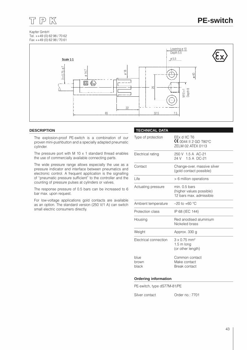
Kapfer GmbHTel. ++49 (0) 62 98 / 70 62Fax ++49 (0) 62 98 / 70 61
43
PE-switch
65
22
32.5 7.5
25
M10
x 1
Dept
h8
40
ø 5,5
Depth 5.5Lowering ø 10
ø 18
ø 14
.7
3 x
0.75
; ø 7
Scale 1:1
DESCRIPTION
The explosion-proof PE-switch is a combination of our proven mini-pushbutton and a specially adapted pneumatic cylinder.
The pressure port with M 10 x 1 standard thread enables the use of commercially available connecting parts.
The wide pressure range allows especially the use as a pressure indicator and interface between pneumatics and electronic control. A frequent application is the signalling of “pneumatic pressure sufficient” to the controller and the counting of pressure pulses at cylinders or valves.
The response pressure of 0.5 bars can be increased to 6 bar max. upon request.
For low-voltage applications gold contacts are available as an option. The standard version (250 V/1 A) can switch small electric consumers directly.
TECHNICAL DATA
Type of protection EEx d IIC T6 0044 II 2 GD T80°C ZELM 02 ATEX 0113
Electrical rating 250 V 1.5 A AC-21 24 V 1.5 A DC-21
Contact Change-over, massive silver (gold contact possible)
Life > 6 million operations
Actuating pressure min. 0.5 bars (higher values possible) 12 bars max. admissible
Ambient temperature –20 to +60 °C
Protection class IP 68 (IEC 144)
Housing Red anodised aluminium Nickeled brass
Weight Approx. 330 g
Electrical connection 3 x 0.75 mm² 1.5 m long (or other length)
blue Common contactbrown Make contactblack Break contact
Ordering information
PE-switch, type dS77M-81/PE
Silver contact Order no.: 7701
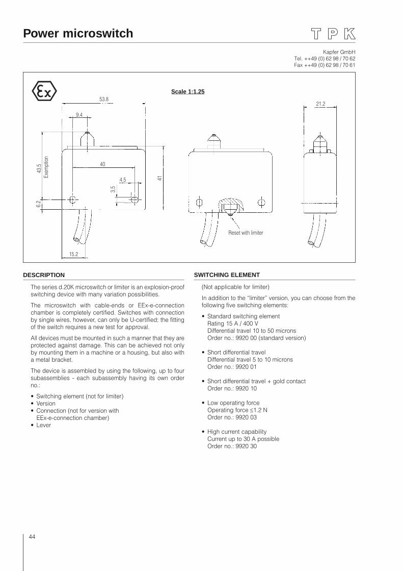
Kapfer GmbHTel. ++49 (0) 62 98 / 70 62Fax ++49 (0) 62 98 / 70 61
44
Power microswitch
15.2
6.2
3,5
4.5
40
43.5
Exem
ptio
n
41
9.4
53.8
Reset with limiter
21.2
Scale 1:1.25
DESCRIPTION
The series d.20K microswitch or limiter is an explosion-proof switching device with many variation possibilities.
The microswitch with cable-ends or EEx-e-connection chamber is completely certified. Switches with connection by single wires, however, can only be U-certified; the fitting of the switch requires a new test for approval.
All devices must be mounted in such a manner that they are protected against damage. This can be achieved not only by mounting them in a machine or a housing, but also with a metal bracket.
The device is assembled by using the following, up to four subassemblies - each subassembly having its own order no.:
• Switching element (not for limiter)• Version• Connection (not for version with EEx-e-connection chamber)• Lever
SWITCHING ELEMENT
(Not applicable for limiter)
In addition to the “limiter” version, you can choose from the following five switching elements:
• Standard switching element Rating 15 A / 400 V
Differential travel 10 to 50 microns Order no.: 9920 00 (standard version)
• Short differential travel Differential travel 5 to 10 microns
Order no.: 9920 01
• Short differential travel + gold contact Order no.: 9920 10
• Low operating force Operating force ≤1.2 N Order no.: 9920 03
• High current capability Current up to 30 A possible Order no.: 9920 30
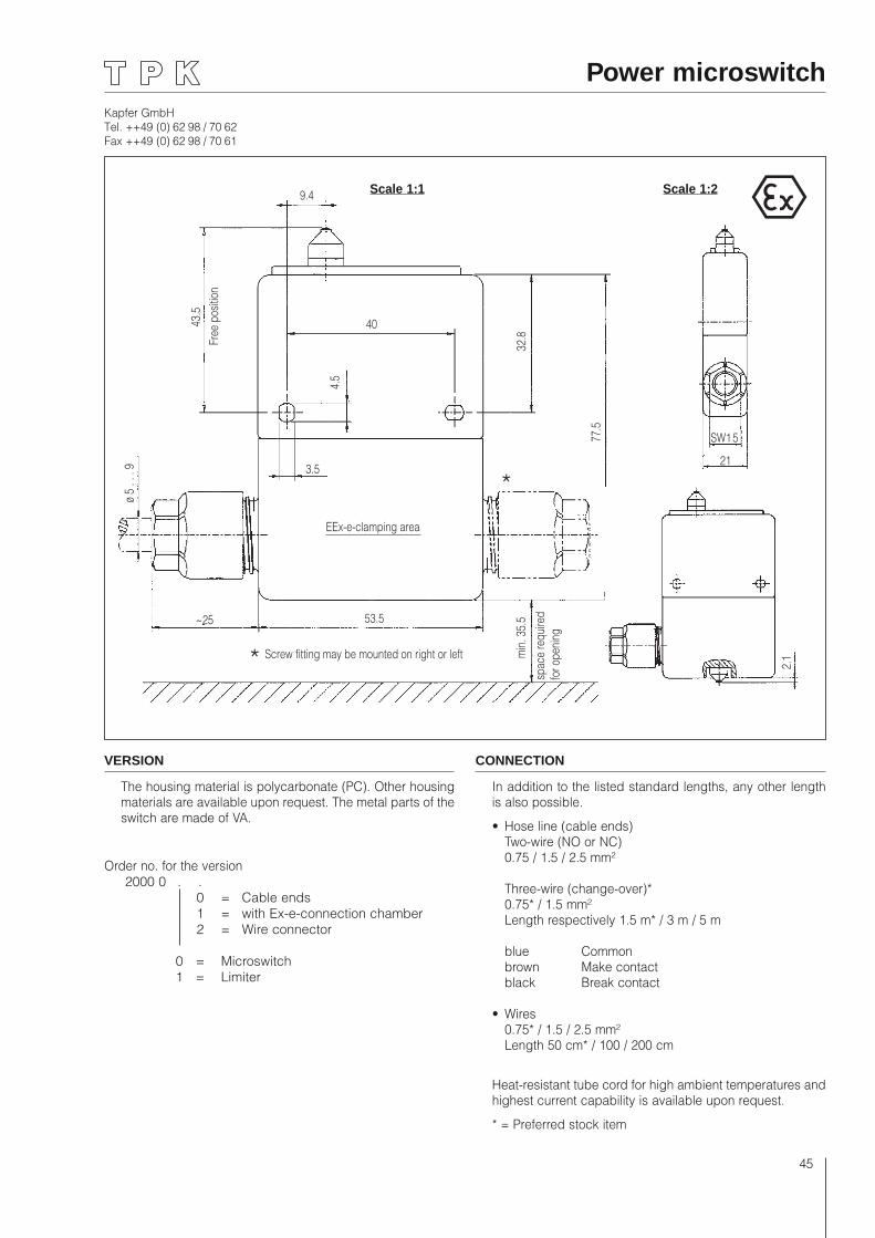
Kapfer GmbHTel. ++49 (0) 62 98 / 70 62Fax ++49 (0) 62 98 / 70 61
45
9.4
404.
5
3.5
EEx-e-clamping area
ø 5
. . .
9
43.5
Free
pos
ition
32.8
77.5
min
. 35.
5sp
ace
requ
ired
for o
peni
ng
53.5
Screw fitting may be mounted on right or left
~25
*
*
2.1
SW1 5
21
Scale 1:2
Power microswitch
Scale 1:1
VERSION
The housing material is polycarbonate (PC). Other housing materials are available upon request. The metal parts of the switch are made of VA.
Order no. for the version 2000 0 . . 0 = Cable ends 1 = with Ex-e-connection chamber 2 = Wire connector
0 = Microswitch 1 = Limiter
CONNECTION
In addition to the listed standard lengths, any other length is also possible.
• Hose line (cable ends) Two-wire (NO or NC) 0.75 / 1.5 / 2.5 mm² Three-wire (change-over)* 0.75* / 1.5 mm² Length respectively 1.5 m* / 3 m / 5 m
blue Common brown Make contact black Break contact
• Wires 0.75* / 1.5 / 2.5 mm² Length 50 cm* / 100 / 200 cm
Heat-resistant tube cord for high ambient temperatures and highest current capability is available upon request.
* = Preferred stock item
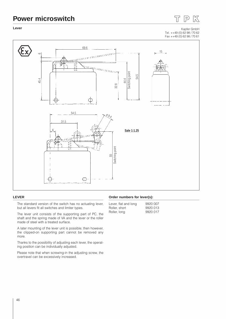
Kapfer GmbHTel. ++49 (0) 62 98 / 70 62Fax ++49 (0) 62 98 / 70 61
46
Power microswitchLever
69.6
645
.4
32.8
44.4
Switc
hing
poi
nt
54.5
54.5
31.5
6
55Sw
itchi
ng p
oint
ø 9.4
Sale 1:1.25
15
LEVER
The standard version of the switch has no actuating lever, but all levers fit all switches and limiter types.
The lever unit consists of the supporting part of PC, the shaft and the spring made of VA and the lever or the roller made of steel with a treated surface.
A later mounting of the lever unit is possible; then however, the clipped-on supporting part cannot be removed any more.
Thanks to the possibility of adjusting each lever, the operat-ing position can be individually adjusted.
Please note that when screwing-in the adjusting screw, the overtravel can be excessively increased.
Order numbers for lever(s):
Lever, flat and long 9920 007Roller, short 9920 013Roller, long 9920 017
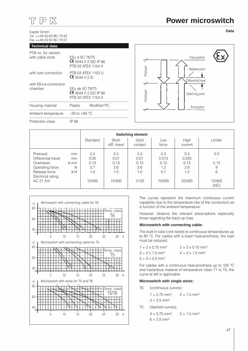
Kapfer GmbHTel. ++49 (0) 62 98 / 70 62Fax ++49 (0) 62 98 / 70 61
47
Power microswitchData
Free position
Release point
Differential travel
Switching point
End position
Over
trave
lPr
etrav
el
5 10 15 20 25 30 A
5 10 15 20 25 30 A
5 10 15 20 25 30 A
80
60
40
°C
80
60
40
°C
80
60
40
°C
T5
T5/T6
T6Temp. class
Temp. class
Temp. class
Switching element
Standard Short Gold Low High Limiter diff. travel contact force current
Pretravel mm 0.4 0.3 0.3 0.3 0.4 0.3 Differential travel mm 0.05 0.01 0.01 0.013 0.025 – Overtravel ≥ mm 0.13 0.13 0.13 0.13 0.13 0.13 Operating force N 3.7 2.6 2.6 1.2 2.8 9 Release force ≥ N 1.0 1.0 1.0 0.7 1.2 6 Electrical rating: AC 21 A/V 15/400 15/400 1/125 10/400 22/400 12/400 (NC)
Technical data
PTB no. for version: with cable ends EEx d IIC T6/T5 0044 II 2 GD IP 66 PTB 02 ATEX 1154 X
with wire connection PTB 02 ATEX 1153 U 0044 II 2 G
with EEx-e-connection chamber EEx de IIC T6/T5 0044 II 2 GD IP 66 PTB 02 ATEX 1154 X
Housing material Plastic Modified PC
Ambient temperature –20 to +80 °C
Protection class IP 66
The curves represent the maximum continuous current capability due to the temperature rise of the conductors as a function of the ambient temperature.
However, observe the relevant prescriptions especially those regarding the back-up fuse.
Microswitch with connecting cable:
The built-in tube cord resists to continuous temperatures up to 80 °C. For cables with a lower heat-proofness, the load must be reduced.
1 = 2 x 0.75 mm² 2 = 3 x 0.75 mm²3 = 2 x 1.5 mm² 4 = 3 x 1.5 mm²5 = 2 x 2.5 mm²
For cables with a continuous heat-proofness up to 105 °C and hazardous material of temperature class T1 to T5, the curve at left is applicable.
Microswitch with single wires:
T6 (continuous curves):
1 = 0.75 mm²; 2 = 1.5 mm² 3 = 2.5 mm²
T5 (dashed curves):
4 = 0.75 mm²; 5 = 1.5 mm² 6 = 2.5 mm²
Microswich with connecting cable for T6
Microswitch with connecting cable for T5
Microswitch with wires for T5 and T6
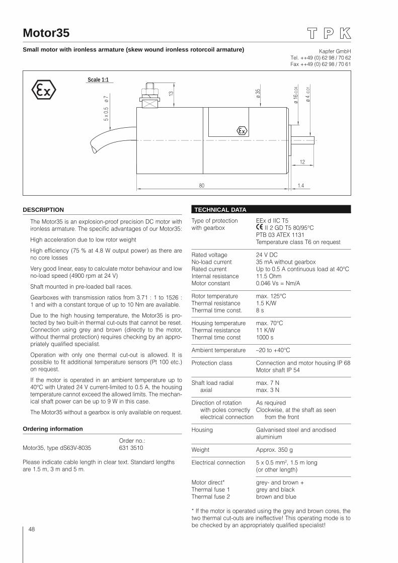
Kapfer GmbHTel. ++49 (0) 62 98 / 70 62Fax ++49 (0) 62 98 / 70 61
48
Motor35Small motor with ironless armature (skew wound ironless rotorcoil armature)
5 x
0.5
ø
7
80
Scale 1:1
ø 35
ø 16 ø 4
-0.0
1
-0.0
4
1.4
1312
DESCRIPTION
The Motor35 is an explosion-proof precision DC motor with ironless armature. The specific advantages of our Motor35:
High acceleration due to low rotor weight
High efficiency (75 % at 4.8 W output power) as there are no core losses
Very good linear, easy to calculate motor behaviour and low no-load speed (4900 rpm at 24 V)
Shaft mounted in pre-loaded ball races.
Gearboxes with transmission ratios from 3.71 : 1 to 1526 : 1 and with a constant torque of up to 10 Nm are available.
Due to the high housing temperature, the Motor35 is pro-tected by two built-in thermal cut-outs that cannot be reset. Connection using grey and brown (directly to the motor, without thermal protection) requires checking by an appro-priately qualified specialist.
Operation with only one thermal cut-out is allowed. It is possible to fit additional temperature sensors (Pt 100 etc.) on request.
If the motor is operated in an ambient temperature up to 40°C with Urated 24 V current-limited to 0.5 A, the housing temperature cannot exceed the allowed limits. The mechan-ical shaft power can be up to 9 W in this case.
The Motor35 without a gearbox is only available on request.
Ordering information
Order no.: Motor35, type dS63V-8035 631 3510
Please indicate cable length in clear text. Standard lengths are 1.5 m, 3 m and 5 m.
TECHNICAL DATA
Type of protection EEx d IIC T5with gearbox II 2 GD T5 80/95°C PTB 03 ATEX 1131 Temperature class T6 on request
Rated voltage 24 V DCNo-load current 35 mA without gearboxRated current Up to 0.5 A continuous load at 40°CInternal resistance 11.5 OhmMotor constant 0.046 Vs = Nm/A
Rotor temperature max. 125°CThermal resistance 1.5 K/WThermal time const. 8 s
Housing temperature max. 70°CThermal resistance 11 K/WThermal time const 1000 s
Ambient temperature –20 to +40°C
Protection class Connection and motor housing IP 68 Motor shaft IP 54
Shaft load radial max. 7 N axial max. 3 N
Direction of rotation As required with poles correctly Clockwise, at the shaft as seen electrical connection from the front
Housing Galvanised steel and anodised aluminium
Weight Approx. 350 g
Electrical connection 5 x 0.5 mm², 1.5 m long (or other length)
Motor direct* grey- and brown +Thermal fuse 1 grey and blackThermal fuse 2 brown and blue
* If the motor is operated using the grey and brown cores, the two thermal cut-outs are ineffective! This operating mode is to be checked by an appropriately qualified specialist!
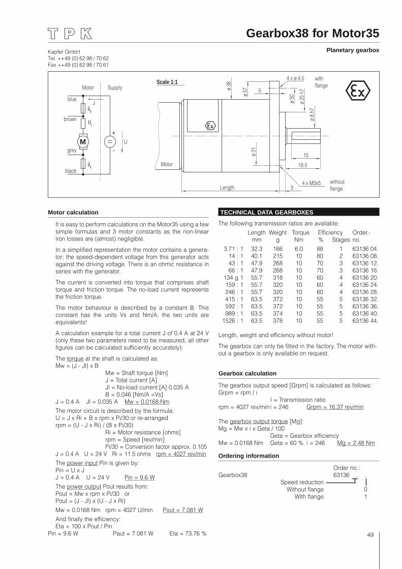
Kapfer GmbHTel. ++49 (0) 62 98 / 70 62Fax ++49 (0) 62 98 / 70 61
49
Gearbox38 for Motor35Planetary gearbox
Length
Scale 1:1
ø 38
3
ø 57
ø 50
4 x ø 4.5
ø 25
h7
ø 8
h7
15
18.5
ø 31
4 x M3x5
Motor
5
M+
-
Motor Supply
brown
grey
black
blue
U
Ri
δ2
δ1
withflange
withoutflange
J
Motor calculation
It is easy to perform calculations on the Motor35 using a few simple formulas and 3 motor constants as the non-linear iron losses are (almost) negligible.
In a simplified representation the motor contains a genera-tor; the speed-dependent voltage from this generator acts against the driving voltage. There is an ohmic resistance in series with the generator.
The current is converted into torque that comprises shaft torque and friction torque. The no-load current represents the friction torque.
The motor behaviour is described by a constant B. This constant has the units Vs and Nm/A; the two units are equivalents!
A calculation example for a total current J of 0.4 A at 24 V (only these two parameters need to be measured, all other figures can be calculated sufficiently accurately):
The torque at the shaft is calculated as:Mw = (J - Jl) x B Mw = Shaft torque [Nm] J = Total current [A] Jl = No-load current [A] 0.035 A B = 0.046 [Nm/A =Vs]J = 0.4 A Jl = 0.035 A Mw = 0.0168 NmThe motor circuit is described by the formula:U = J x Ri + B x rpm x Pi/30 or re-arrangedrpm = (U - J x Ri) / (B x Pi/30) Ri = Motor resistance [ohms] rpm = Speed [rev/min] Pi/30 = Conversion factor approx. 0.105J = 0.4 A U = 24 V Ri = 11.5 ohms rpm = 4027 rev/minThe power input Pin is given by:Pin = U x JJ = 0.4 A U = 24 V Pin = 9.6 WThe power output Pout results from:Pout = Mw x rpm x Pi/30 orPout = (J - Jl) x (U - J x Ri)Mw = 0.0168 Nm rpm = 4027 U/min Pout = 7.081 WAnd finally the efficiency:Eta = 100 x Pout / Pin
Pin = 9.6 W Paut = 7.081 W Eta = 73.76 %
TECHNICAL DATA GEARBOXES
The following transmission ratios are available: Length Weight Torque Efficiency Order.- mm g Nm % Stages no. 3.71 : 1 32.3 166 6.0 88 1 63136 04. 14 : 1 40.1 215 10 80 2 63136 08. 43 : 1 47.9 268 10 70 3 63136 12. 66 : 1 47.9 268 10 70 3 63136 16. 134 g 1 55.7 318 10 60 4 63136 20. 159 : 1 55.7 320 10 60 4 63136 24. 246 : 1 55.7 320 10 60 4 63136 28. 415 : 1 63.5 372 10 55 5 63136 32. 592 : 1 63.5 372 10 55 5 63136 36. 989 : 1 63.5 374 10 55 5 63136 40. 1526 : 1 63.5 378 10 55 5 63136 44.
Length, weight and efficiency without motor!
The gearbox can only be fitted in the factory. The motor with-out a gearbox is only available on request.
Gearbox calculation
The gearbox output speed [Grpm] is calculated as follows:Grpm = rpm / i I = Transmission ratiorpm = 4027 rev/min i = 246 Grpm = 16.37 rev/min
The gearbox output torque [Mg]:Mg = Mw x i x Geta / 100 Geta = Gearbox efficiencyMw = 0.0168 Nm Geta = 60 % i = 246 Mg = 2.48 Nm
Ordering information
Order no.:Gearbox38 63136 . . . Speed reduction Without flange 0 With flange 1
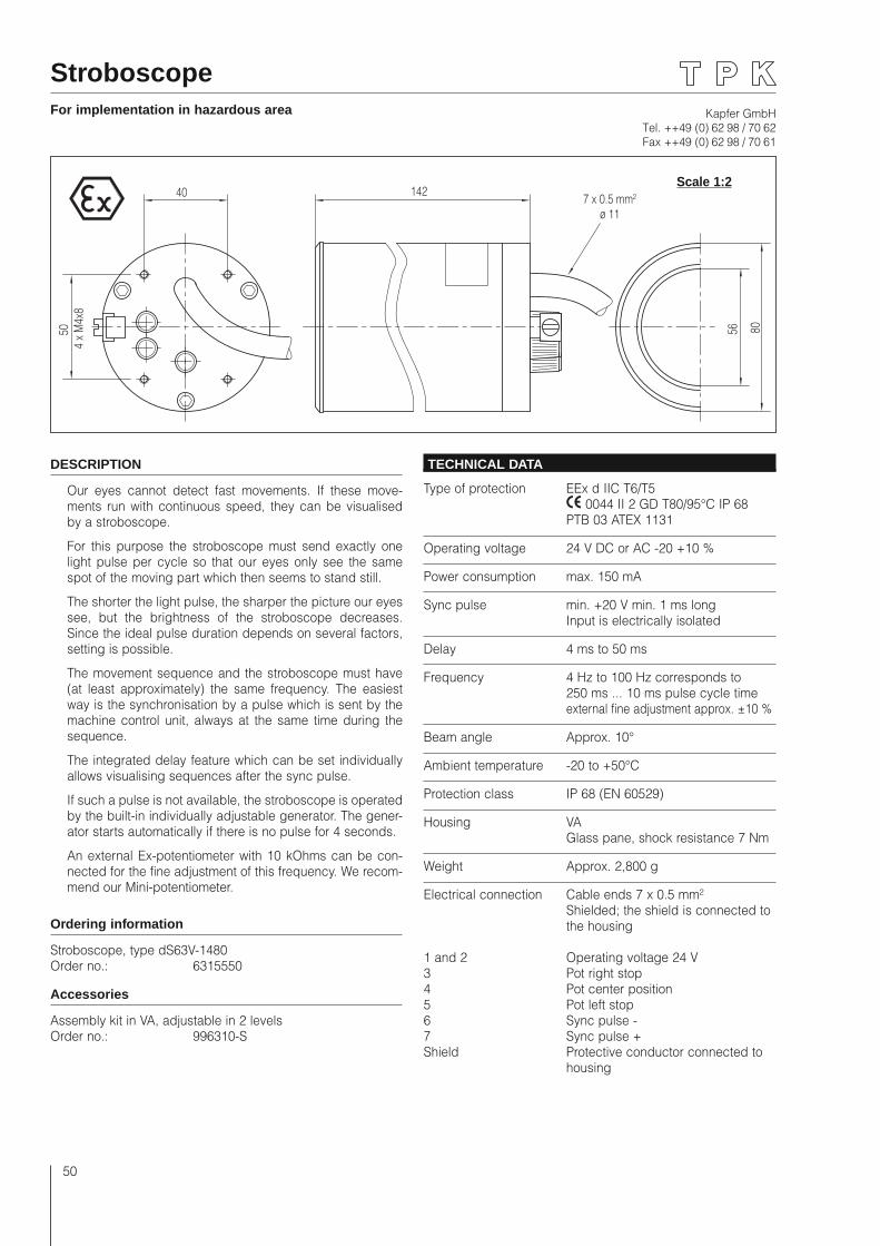
Kapfer GmbHTel. ++49 (0) 62 98 / 70 62Fax ++49 (0) 62 98 / 70 61
50
StroboscopeFor implementation in hazardous area
40 142
56 8050 4
x M
4x8
7 x 0.5 mm²ø 11
DESCRIPTION
Our eyes cannot detect fast movements. If these move-ments run with continuous speed, they can be visualised by a stroboscope.
For this purpose the stroboscope must send exactly one light pulse per cycle so that our eyes only see the same spot of the moving part which then seems to stand still.
The shorter the light pulse, the sharper the picture our eyes see, but the brightness of the stroboscope decreases. Since the ideal pulse duration depends on several factors, setting is possible.
The movement sequence and the stroboscope must have (at least approximately) the same frequency. The easiest way is the synchronisation by a pulse which is sent by the machine control unit, always at the same time during the sequence.
The integrated delay feature which can be set individually allows visualising sequences after the sync pulse.
If such a pulse is not available, the stroboscope is operated by the built-in individually adjustable generator. The gener-ator starts automatically if there is no pulse for 4 seconds.
An external Ex-potentiometer with 10 kOhms can be con-nected for the fine adjustment of this frequency. We recom-mend our Mini-potentiometer.
Ordering information
Stroboscope, type dS63V-1480Order no.: 6315550
Accessories
Assembly kit in VA, adjustable in 2 levelsOrder no.: 996310-S
TECHNICAL DATA
Type of protection EEx d IIC T6/T5 0044 II 2 GD T80/95°C IP 68 PTB 03 ATEX 1131
Operating voltage 24 V DC or AC -20 +10 %
Power consumption max. 150 mA
Sync pulse min. +20 V min. 1 ms long Input is electrically isolated
Delay 4 ms to 50 ms
Frequency 4 Hz to 100 Hz corresponds to 250 ms ... 10 ms pulse cycle time external fine adjustment approx. ±10 %
Beam angle Approx. 10°
Ambient temperature -20 to +50°C
Protection class IP 68 (EN 60529)
Housing VA Glass pane, shock resistance 7 Nm
Weight Approx. 2,800 g
Electrical connection Cable ends 7 x 0.5 mm² Shielded; the shield is connected to the housing
1 and 2 Operating voltage 24 V3 Pot right stop4 Pot center position5 Pot left stop6 Sync pulse -7 Sync pulse +Shield Protective conductor connected to housing
Scale 1:2
Kapfer GmbHTel. ++49 (0) 62 98 / 70 62Fax ++49 (0) 62 98 / 70 61
51
StroboscopeFor implementation in hazardous area
Operating instructions
General
The red control knob has 3 positions: Off, Stroboscope operation, Continuous operation.
These instructions are based on a moving part (=object) which is rotating. The basic function is the same for con-veyer-belt operations.
The two adjusting devices (black and grey) on the rear side have18 turns and no stops. Overwinding therefore is not possible.
Frequency and delay are only adjusted by one adjusting device (grey colour), since only either the frequency of the free running generator or the delay is needed.
Delay (only for operation with sync pulse): turn clockwise
= delay decreases
Frequency (only for free running operation): turn clockwise
= Frequency increases
The adjusting device “Pulse” (black with yellow cap) chang-es the duration of the light pulse. The shorter the light pulse, the clearer the view of the object. However, a short light pulse also means less brightness. Therefore the result is better if the object is protected from the ambient light.
Turn "Pulse" clockwise
= pulse takes longer
First turn both adjusting devices approx. 20 turns clock-wise. The delay then is minimal, the frequency for the free running mode is maximal and the light pulse very long.
Operation with sync pulse
The fine adjustment is not required. Please connect the wires 3, 4 and 5 together.
The input for the sync pulse is electrically isolated from the operating voltage within the stroboscope.
The sync pulse has to be present at the input once per turn. The flashlight is triggered by the rising edge of the sync pulse.
If the sync pulse exceeds 10 V permanently, the strobo-scope is switched off.
If no sync pulse is detected (sync pulse too short, ampli-tude too small, or negative polarity), the stroboscope acti-vates the internal generator after 4 seconds automatically, but reacts immediately if there is a sufficient positive sync pulse.
When the flashlights are triggered by sync pulse, the object seems to stand still.
Then turn the adjusting device “Pulse” anti-clockwise (=darker) until the best proportion of sharpness and bright-ness is adjusted.
The adjusting device “Delay” allows to delay the sync pulse. So the object seems to be turned.
During the delay, the sync pulse input is blocked. If the set delay exceeds one cycle, the following sync pulse is dis-abled. This allows to suppress sync pulses when the control unit triggers more than one pulse per turn.
Free running operation, without sync pulse
During the free running operation it is hardly possible to avoid that, from time to time, the object turns slowly. This is due to the fact that the speed is mostly not constant and that the speed of the free running generator can drift a little. A readjustment is always possible with the option-al fine adjustment on-site. We recommend our Ex-mini-potentiometer with 10kOhms.
For the fine adjustment connect the Ex-mini-potentiometer (10 kOhms) to 4, 5 and 6 and turn to the neutral position. If the fine adjustment is not necessary, connect the wires 3, 4 and 5 together.
The sync pulse is not required. Please connect the wires 6 and 7 together.
If the grey adjustment device “Frequency and delay” has been turned clockwise, light pulses with the highest pos-sible frequency, which can be reduced by the adjusting device.
First, the frequency of the stroboscope is higher than the speed of the object. Slowly reduce the frequency (turn anti-clockwise). If, for example, the frequency is the double of the speed of the object, the image stands still, but front and back are visible at the same time.
If the frequency is half as high as the speed, the object seems to stand still as if with the right frequency. Since the light pulses only illuminate at every second turn, the object is very dark.
Particularly for uniform objects (e.g. gear-wheels), it might be difficult to find the right frequency. An irregular sign (e.g. applied with felt pen) on the object makes adjusting much more easy.
It might also be helpful to shorten the pulse (black adjusting device turned anti-clockwise) until the brightness is just about to be sufficient.
If the right frequency is set, turn the adjusting device “Pulse” (anti-clockwise =darker) until the best proportion of sharpness and brightness is adjusted.
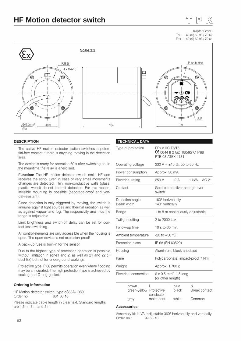
Kapfer GmbHTel. ++49 (0) 62 98 / 70 62Fax ++49 (0) 62 98 / 70 61
52
HF Motion detector switch
40.3
4 x M4x10
891046x0.5mm²Ø 8
LED
Push-buttonR28.5
DESCRIPTION
The active HF motion detector switch switches a poten-tial-free contact if there is anything moving in the detection area.
The device is ready for operation 60 s after switching on. In the meantime the relay is energised.
Function: The HF motion detector switch emits HF and receives the echo. Even in case of very small movements changes are detected. Thin, non-conductive walls (glass, plastic, wood) do not intermit detection. For this reason, invisible mounting is possible (sabotage-proof and van-dal-resistant).
Since detection is only triggered by moving, the switch is immune against light sources and thermal radiation as well as against vapour and fog. The responsivity and thus the range is adjustable.
Limit brightness and switch-off delay can be set for con-tact-less switching.
All control elements are only accessible when the housing is open. The open device is not explosion-proof!
A back-up fuse is built-in for the sensor.
Due to the highest type of protection operation is possible without limitation in zone1 and 2, as well as 21 and 22 (= dust-Ex) but not for underground workings.
Protection type IP 68 permits operation even where flooding may be anticipated. The high protection type is achieved by sealing and O-ring gasket.
Ordering information
HF Motion detector switch, type dS63A-1089Order no.: 631 60 10
Please indicate cable length in clear text. Standard lengths are 1.5 m, 3 m and 5 m.
TECHNICAL DATA
Type of protection EEx d IIC T6/T5 0044 II 2 GD T80/95°C IP68 PTB 03 ATEX 1131
Operating voltage 230 V ~ ±15 %, 50 to 60 Hz
Power consumption Approx. 30 mA
Electrical rating 250 V 2 A 1 kVA AC 21
Contact Gold-plated silver change-over switch
Detection angle 160° horizontally Beam width 140° vertically
Range 1 to 8 m continuously adjustable
Twilight setting 2 to 2000 Lux
Follow-up time 10 s to 30 min.
Ambient temperature -20 to +50 °C
Protection class IP 68 (EN 60529)
Housing Aluminium, black anodised
Pane Polycarbonate, impact-proof 7 Nm
Weight Approx. 1,700 g
Electrical connection 6 x 0.5 mm², 1.5 long (or other length)
brown L blue N green-yellow Protective black Break contact conductor grey make cont. white Common
Accessories
Assembly kit in VA, adjustable 360° horizontally and vertically.Order no.: 99 63 10
Scale 1:2
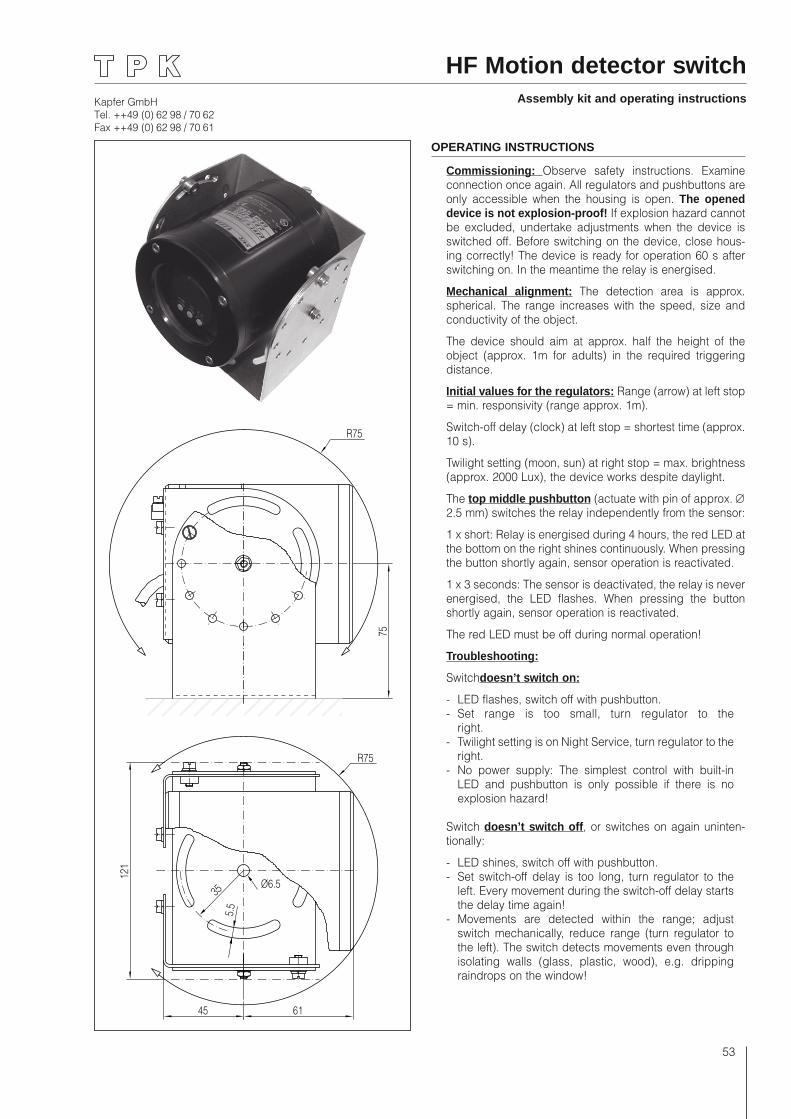
Kapfer GmbHTel. ++49 (0) 62 98 / 70 62Fax ++49 (0) 62 98 / 70 61
53
HF Motion detector switchAssembly kit and operating instructions
121
45 61
75
R75
R75
35
5.5
Ø6.5
OPERATING INSTRUCTIONS
Commissioning: Observe safety instructions. Examine connection once again. All regulators and pushbuttons are only accessible when the housing is open. The opened device is not explosion-proof! If explosion hazard cannot be excluded, undertake adjustments when the device is switched off. Before switching on the device, close hous-ing correctly! The device is ready for operation 60 s after switching on. In the meantime the relay is energised.
Mechanical alignment: The detection area is approx. spherical. The range increases with the speed, size and conductivity of the object.
The device should aim at approx. half the height of the object (approx. 1m for adults) in the required triggering distance.
Initial values for the regulators: Range (arrow) at left stop = min. responsivity (range approx. 1m).
Switch-off delay (clock) at left stop = shortest time (approx. 10 s).
Twilight setting (moon, sun) at right stop = max. brightness (approx. 2000 Lux), the device works despite daylight.
The top middle pushbutton (actuate with pin of approx. ∅ 2.5 mm) switches the relay independently from the sensor:
1 x short: Relay is energised during 4 hours, the red LED at the bottom on the right shines continuously. When pressing the button shortly again, sensor operation is reactivated.
1 x 3 seconds: The sensor is deactivated, the relay is never energised, the LED flashes. When pressing the button shortly again, sensor operation is reactivated.
The red LED must be off during normal operation!
Troubleshooting:
Switchdoesn’t switch on:
- LED flashes, switch off with pushbutton.- Set range is too small, turn regulator to the
right.- Twilight setting is on Night Service, turn regulator to the
right.- No power supply: The simplest control with built-in
LED and pushbutton is only possible if there is no explosion hazard!
Switch doesn’t switch off, or switches on again uninten-tionally:
- LED shines, switch off with pushbutton.- Set switch-off delay is too long, turn regulator to the
left. Every movement during the switch-off delay starts the delay time again!
- Movements are detected within the range; adjust switch mechanically, reduce range (turn regulator to the left). The switch detects movements even through isolating walls (glass, plastic, wood), e.g. dripping raindrops on the window!
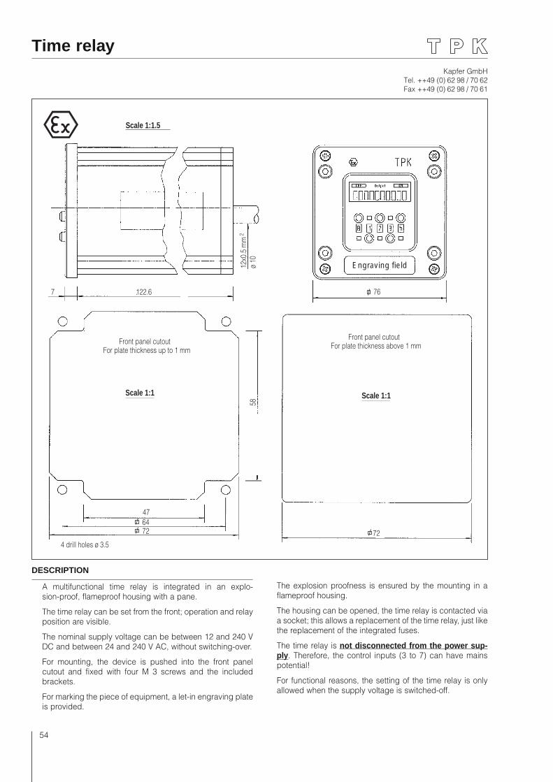
Kapfer GmbHTel. ++49 (0) 62 98 / 70 62Fax ++49 (0) 62 98 / 70 61
54
Scale 1:1.5
122.67
Front panel cutoutFor plate thickness up to 1 mm
12x0
.5 m
m2
ø 10
Scale 1:1
58
47 64 72
4 drill holes ø 3.5
Scale 1:1.5
122.67
Front panel cutoutFor plate thickness up to 1 mm
12x0
.5 m
m2
ø 10
Scale 1:1
58
47 64 72
4 drill holes ø 3.5
76
Front panel cutoutFor plate thickness above 1 mm
Scale 1:1
72
Engraving field76
Front panel cutoutFor plate thickness above 1 mm
Scale 1:1
72
Engraving field
Time relay
DESCRIPTION
A multifunctional time relay is integrated in an explo-sion-proof, flameproof housing with a pane.
The time relay can be set from the front; operation and relay position are visible.
The nominal supply voltage can be between 12 and 240 V DC and between 24 and 240 V AC, without switching-over.
For mounting, the device is pushed into the front panel cutout and fixed with four M 3 screws and the included brackets.
For marking the piece of equipment, a let-in engraving plate is provided.
The explosion proofness is ensured by the mounting in a flameproof housing.
The housing can be opened, the time relay is contacted via a socket; this allows a replacement of the time relay, just like the replacement of the integrated fuses.
The time relay is not disconnected from the power sup-ply. Therefore, the control inputs (3 to 7) can have mains potential!
For functional reasons, the setting of the time relay is only allowed when the supply voltage is switched-off.
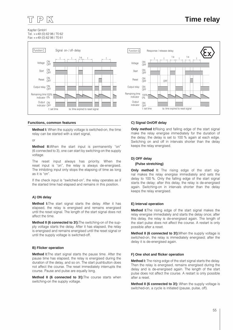
Kapfer GmbHTel. ++49 (0) 62 98 / 70 62Fax ++49 (0) 62 98 / 70 61
55
Time relay
Voltage
Start
Reset
Output relay
Remaining timeindicator
Outputindicator
ONOFF
ONOFF
ONOFF
ONOFF
ONOFF
100%0%
t: set time ta: time expired to reset signal
t t t tt-a
Function C Signal on- / off- delay
ONOFF
ONOFF
ONOFF
ONOFF
ONOFF
100%0%
t t tt-a
Function G Response / release delay
t-at
OFF
Voltage
Start
Reset
Output relay
Remaining timeindicator
Outputindicator
t: set time ta: time expired to reset signal
Functions, common features
Method I: When the supply voltage is switched-on, the time relay can be started with a start signal,
or
Method II:When the start input is permanently “on” (6 connected to 3), one can start by switching-on the supply voltage.
The reset input always has priority. When the reset input is “on”, the relay is always de-energised. The inhibiting input only stops the elapsing of time as long as it is “on”.
If the check input is “switched-on”, the relay operates as if the started time had elapsed and remains in this position.
A) ON delay
Method I:The start signal starts the delay. After it has elapsed, the relay is energised and remains energised until the reset signal. The length of the start signal does not affect the time.
Method II (6 connected to 3!):The switching-on of the sup-ply voltage starts the delay. After it has elapsed, the relay is energised and remains energised until the reset signal or until the supply voltage is switched-off.
B) Flicker operation
Method I:The start signal starts the pause time. After the pause time has elapsed, the relay is energised during the duration of the delay, and so on. The start pushbutton does not affect the course. The reset immediately interrupts the course. Pause and pulse are equally long.
Method II (6 connected to 3!):The course starts when switching-on the supply voltage.
C) Signal On/Off delay
Only method I:Rising and falling edge of the start signal make the relay energise immediately for the duration of the delay; the delay is set to 100 % again at each edge. Switching on and off in intervals shorter than the delay keeps the relay energised.
D) OFF delay
(Pulse stretching)
Only method I: The rising edge of the start sig-nal makes the relay energise immediately and sets the delay to 100 %. Only the falling edge of the start signal starts the delay; after this delay, the relay is de-energised again. Switching-on in intervals shorter than the delay keeps the relay energised.
E) Interval operation
Method I:The rising edge of the start signal makes the relay energise immediately and starts the delay once; after this delay, the relay is de-energised again. The length of the start pulse does not affect the course. A restart is only possible after a reset.
Method II (6 connected to 3!):When the supply voltage is switched-on, the relay is immediately energised; after the delay it is de-energised again.
F) One shot and flicker operation
Method I: The rising edge of the start signal starts the delay. Then the relay is energised, remains energised during the delay and is de-energised again. The length of the start pulse does not affect the course. A restart is only possible after a reset.
Method II (6 connected to 3!): When the supply voltage is switched-on, a cycle is initiated (pause, pulse, off).
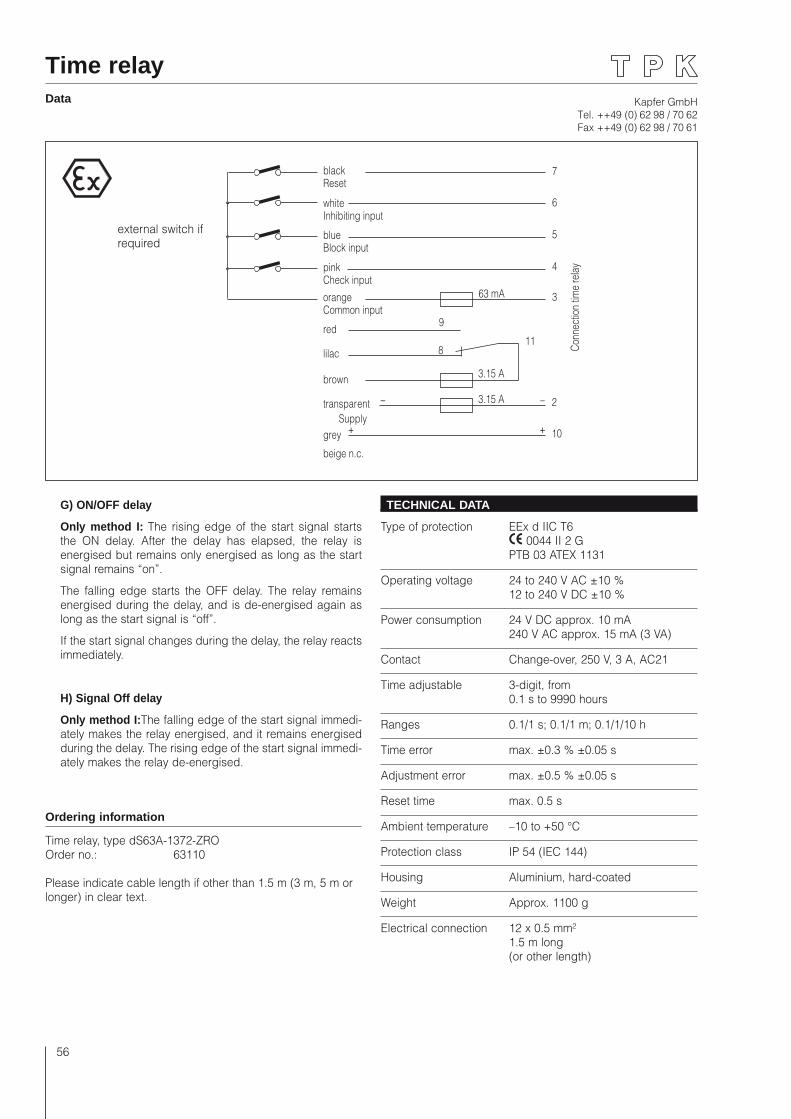
Kapfer GmbHTel. ++49 (0) 62 98 / 70 62Fax ++49 (0) 62 98 / 70 61
56
Time relayData
blackReset
whiteInhibiting input
blueBlock input
pinkCheck inputorangeCommon input
red
lilac
brown
9
8
transparent
grey
beige n.c.
Supply
3.15 A
3.15 A
11
2
10
63 mA 3
4
5
6
7
Conn
ectio
n tim
e re
lay
_
++
_
G) ON/OFF delay
Only method I: The rising edge of the start signal starts the ON delay. After the delay has elapsed, the relay is energised but remains only energised as long as the start signal remains “on”.
The falling edge starts the OFF delay. The relay remains energised during the delay, and is de-energised again as long as the start signal is “off”.
If the start signal changes during the delay, the relay reacts immediately.
H) Signal Off delay
Only method I:The falling edge of the start signal immedi-ately makes the relay energised, and it remains energised during the delay. The rising edge of the start signal immedi-ately makes the relay de-energised.
Ordering information
Time relay, type dS63A-1372-ZROOrder no.: 63110
Please indicate cable length if other than 1.5 m (3 m, 5 m or longer) in clear text.
TECHNICAL DATA
Type of protection EEx d IIC T6 0044 II 2 G PTB 03 ATEX 1131
Operating voltage 24 to 240 V AC ±10 % 12 to 240 V DC ±10 %
Power consumption 24 V DC approx. 10 mA 240 V AC approx. 15 mA (3 VA)
Contact Change-over, 250 V, 3 A, AC21
Time adjustable 3-digit, from 0.1 s to 9990 hours
Ranges 0.1/1 s; 0.1/1 m; 0.1/1/10 h
Time error max. ±0.3 % ±0.05 s
Adjustment error max. ±0.5 % ±0.05 s
Reset time max. 0.5 s
Ambient temperature –10 to +50 °C
Protection class IP 54 (IEC 144)
Housing Aluminium, hard-coated
Weight Approx. 1100 g
Electrical connection 12 x 0.5 mm² 1.5 m long (or other length)
external switch if required
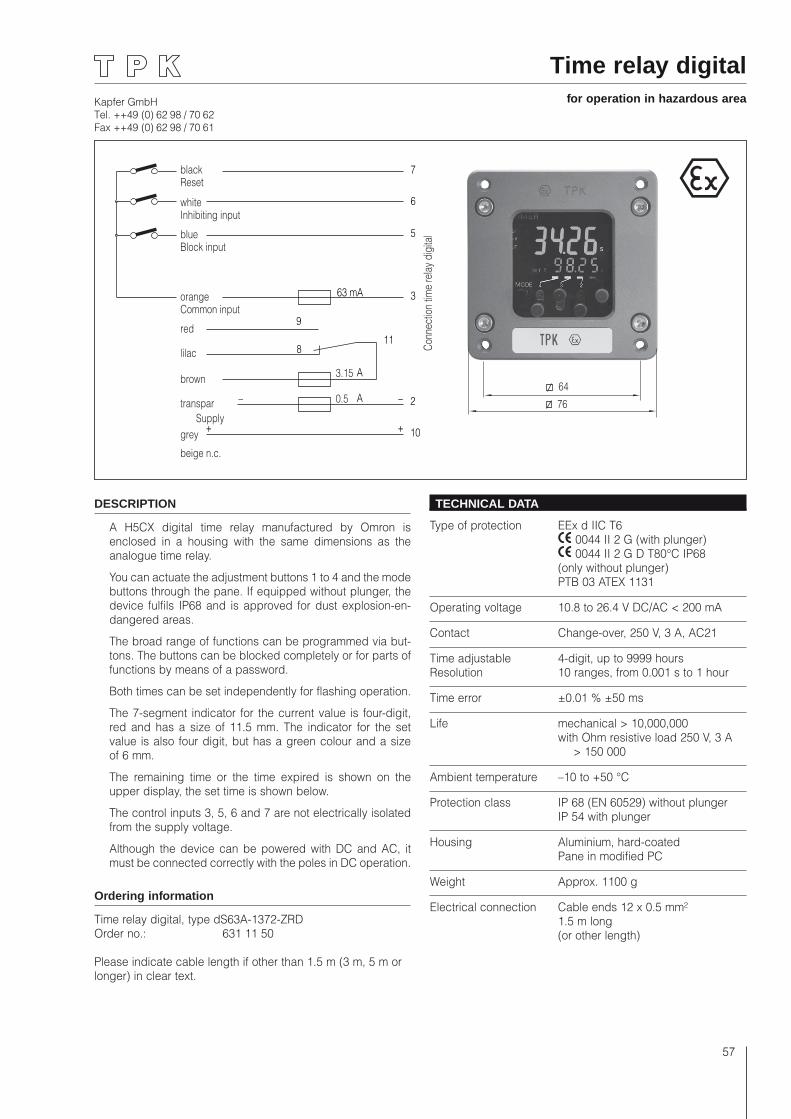
Kapfer GmbHTel. ++49 (0) 62 98 / 70 62Fax ++49 (0) 62 98 / 70 61
57
Time relay digitalfor operation in hazardous area
9
8
A
A
11
2
10
63 mA 3
5
6
7blackReset
whiteInhibiting input
blueBlock input
orangeCommon input
red
lilac
brown
transpar
grey
beige n.c.
Supply
3.15
0.5
Conn
ectio
n tim
e re
lay
digi
tal
_
++
_
DESCRIPTION
A H5CX digital time relay manufactured by Omron is enclosed in a housing with the same dimensions as the analogue time relay.
You can actuate the adjustment buttons 1 to 4 and the mode buttons through the pane. If equipped without plunger, the device fulfils IP68 and is approved for dust explosion-en-dangered areas.
The broad range of functions can be programmed via but-tons. The buttons can be blocked completely or for parts of functions by means of a password.
Both times can be set independently for flashing operation.
The 7-segment indicator for the current value is four-digit, red and has a size of 11.5 mm. The indicator for the set value is also four digit, but has a green colour and a size of 6 mm.
The remaining time or the time expired is shown on the upper display, the set time is shown below.
The control inputs 3, 5, 6 and 7 are not electrically isolated from the supply voltage.
Although the device can be powered with DC and AC, it must be connected correctly with the poles in DC operation.
Ordering information
Time relay digital, type dS63A-1372-ZRDOrder no.: 631 11 50
Please indicate cable length if other than 1.5 m (3 m, 5 m or longer) in clear text.
TECHNICAL DATA
Type of protection EEx d IIC T6 0044 II 2 G (with plunger) 0044 II 2 G D T80°C IP68 (only without plunger) PTB 03 ATEX 1131
Operating voltage 10.8 to 26.4 V DC/AC < 200 mA
Contact Change-over, 250 V, 3 A, AC21
Time adjustable 4-digit, up to 9999 hoursResolution 10 ranges, from 0.001 s to 1 hour
Time error ±0.01 % ±50 ms
Life mechanical > 10,000,000 with Ohm resistive load 250 V, 3 A > 150 000
Ambient temperature –10 to +50 °C
Protection class IP 68 (EN 60529) without plunger IP 54 with plunger
Housing Aluminium, hard-coated Pane in modified PC
Weight Approx. 1100 g
Electrical connection Cable ends 12 x 0.5 mm² 1.5 m long (or other length)
76
64
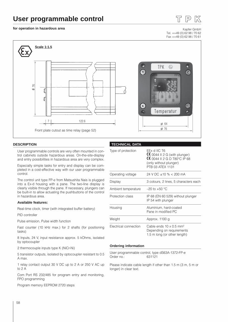
Kapfer GmbHTel. ++49 (0) 62 98 / 70 62Fax ++49 (0) 62 98 / 70 61
58
122.67
76
User programmable controlfor operation in hazardous area
DESCRIPTION
User programmable controls are very often mounted in con-trol cabinets outside hazardous areas. On-the-site-display and entry possibilities in hazardous area are very complex.
Especially simple tasks for entry and display can be com-pleted in a cost-effective way with our user programmable control.
The control unit type FP-e from Matsushita Nais is plugged into a Ex-d housing with a pane. The two-line display is clearly visible through the pane. If necessary, plungers can be built-in to allow actuating the pushbuttons of the control in hazardous area.
Available features:
Real-time clock, timer (with integrated buffer battery)
PID controller
Pulse emission, Pulse width function
Fast counter (10 kHz max.) for 2 shafts (for positioning tasks)
8 Inputs, 24 V, input resistance approx. 5 kOhms, isolated by optocoupler
2 thermocouple inputs type K (NiCr-Ni)
5 transistor outputs, isolated by optocoupler resistant to 0.5 A max.
1 relay contact output 30 V DC up to 2 A or 250 V AC up to 2 A
Com Port RS 232/485 for program entry and monitoring, FPO programming
Program memory EEPROM 2720 steps
TECHNICAL DATA
Type of protection EEx d IIC T6 0044 II 2 G (with plunger) 0044 II 2 G D T80°C IP 68 (only without plunger) PTB 03 ATEX 1131
Operating voltage 24 V DC ±10 % < 200 mA
Display 3 colours, 2 lines, 5 characters each
Ambient temperature –20 to +50 °C
Protection class IP 68 (EN 60 529) without plunger IP 54 with plunger
Housing Aluminium, hard-coated Pane in modified PC
Weight Approx. 1100 g
Electrical connection Cable ends 10 x 0.5 mm² Depending on requirements 1.5 m long (or other length)
Ordering information
User programmable control, type dS63A-1372-FP-eOrder no.: 631121
Please indicate cable length if other than 1.5 m (3 m, 5 m or longer) in clear text.
Scale 1:1.5
76
64
Front plate cutout as time relay (page 52)
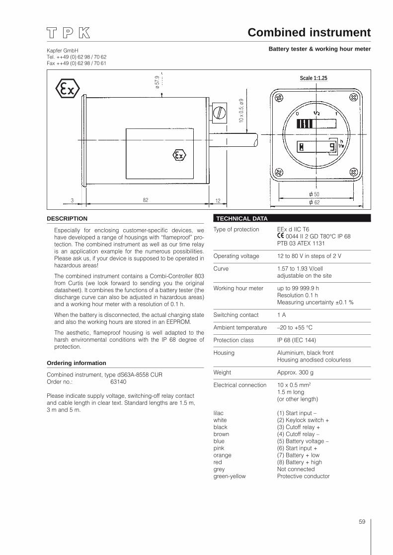
Kapfer GmbHTel. ++49 (0) 62 98 / 70 62Fax ++49 (0) 62 98 / 70 61
59
Combined instrumentBattery tester & working hour meter
Scale 1:1.25
3 82 12
10 x
0.5
; ø 9
ø 57
.9
5062
Scale 1:1.25
3 82 12
10 x
0.5
; ø 9
ø 57
.9
5062
DESCRIPTION
Especially for enclosing customer-specific devices, we have developed a range of housings with “flameproof” pro-tection. The combined instrument as well as our time relay is an application example for the numerous possibilities. Please ask us, if your device is supposed to be operated in hazardous areas!
The combined instrument contains a Combi-Controller 803 from Curtis (we look forward to sending you the original datasheet). It combines the functions of a battery tester (the discharge curve can also be adjusted in hazardous areas) and a working hour meter with a resolution of 0.1 h.
When the battery is disconnected, the actual charging state and also the working hours are stored in an EEPROM.
The aesthetic, flameproof housing is well adapted to the harsh environmental conditions with the IP 68 degree of protection.
Ordering information
Combined instrument, type dS63A-8558 CUROrder no.: 63140
Please indicate supply voltage, switching-off relay contact and cable length in clear text. Standard lengths are 1.5 m, 3 m and 5 m.
TECHNICAL DATA
Type of protection EEx d IIC T6 0044 II 2 GD T80°C IP 68 PTB 03 ATEX 1131
Operating voltage 12 to 80 V in steps of 2 V
Curve 1.57 to 1.93 V/cell adjustable on the site
Working hour meter up to 99 999.9 h Resolution 0.1 h
Measuring uncertainty ±0.1 %
Switching contact 1 A
Ambient temperature –20 to +55 °C
Protection class IP 68 (IEC 144)
Housing Aluminium, black front Housing anodised colourless
Weight Approx. 300 g
Electrical connection 10 x 0.5 mm² 1.5 m long (or other length)
lilac (1) Start input –white (2) Keylock switch + black (3) Cutoff relay + brown (4) Cutoff relay –blue (5) Battery voltage –pink (6) Start input + orange (7) Battery + low red (8) Battery + high grey Not connected green-yellow Protective conductor
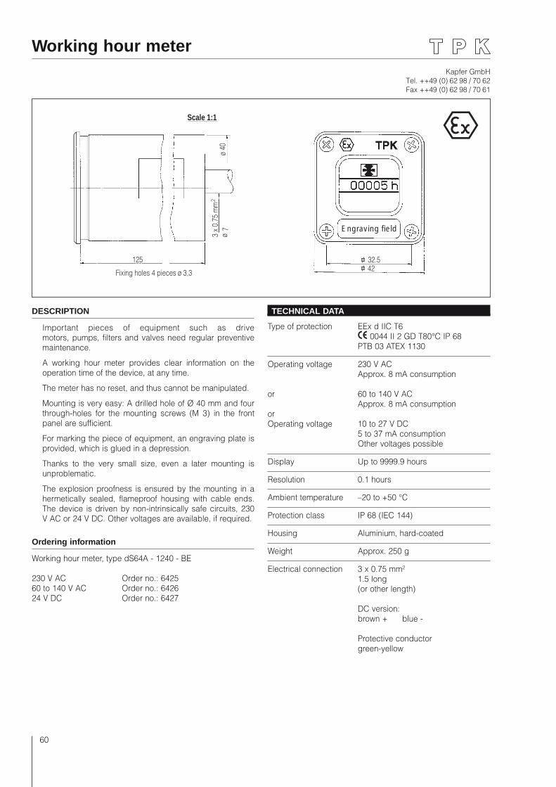
Kapfer GmbHTel. ++49 (0) 62 98 / 70 62Fax ++49 (0) 62 98 / 70 61
60
Working hour meter
Scale 1:1
ø 40
ø 7
3 x
0.75
mm
2
125
Fixing holes 4 pieces ø 3,3
32.542
Engraving field
DESCRIPTION
Important pieces of equipment such as drive motors, pumps, filters and valves need regular preventive maintenance.
A working hour meter provides clear information on the operation time of the device, at any time.
The meter has no reset, and thus cannot be manipulated.
Mounting is very easy: A drilled hole of Ø 40 mm and four through-holes for the mounting screws (M 3) in the front panel are sufficient.
For marking the piece of equipment, an engraving plate is provided, which is glued in a depression.
Thanks to the very small size, even a later mounting is unproblematic.
The explosion proofness is ensured by the mounting in a hermetically sealed, flameproof housing with cable ends. The device is driven by non-intrinsically safe circuits, 230 V AC or 24 V DC. Other voltages are available, if required.
Ordering information
Working hour meter, type dS64A - 1240 - BE
230 V AC Order no.: 642560 to 140 V AC Order no.: 642624 V DC Order no.: 6427
TECHNICAL DATA
Type of protection EEx d IIC T6 0044 II 2 GD T80°C IP 68 PTB 03 ATEX 1130
Operating voltage 230 V AC Approx. 8 mA consumption
or 60 to 140 V AC Approx. 8 mA consumptionor Operating voltage 10 to 27 V DC 5 to 37 mA consumption Other voltages possible
Display Up to 9999.9 hours
Resolution 0.1 hours
Ambient temperature –20 to +50 °C
Protection class IP 68 (IEC 144)
Housing Aluminium, hard-coated
Weight Approx. 250 g
Electrical connection 3 x 0.75 mm² 1.5 long (or other length)
DC version: brown + blue -
Protective conductor green-yellow
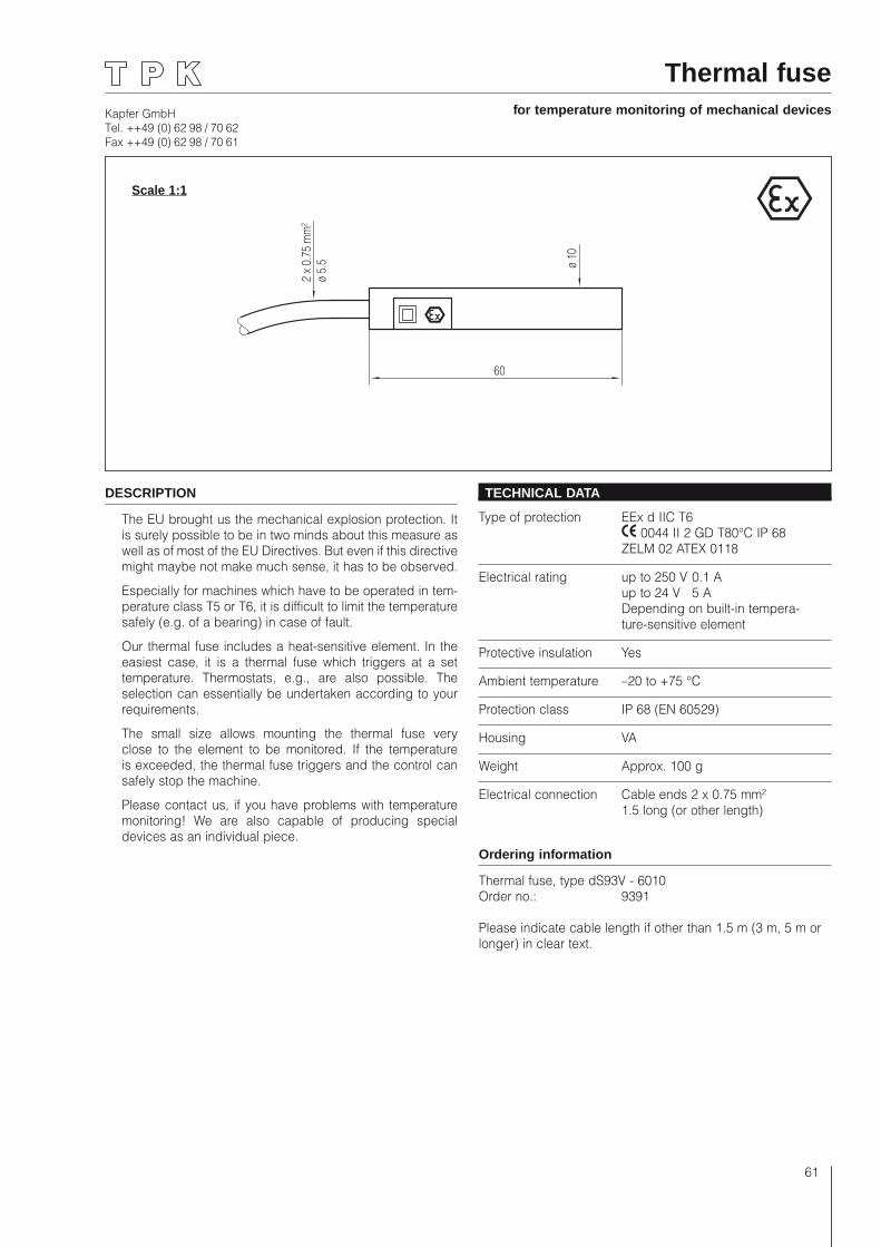
Kapfer GmbHTel. ++49 (0) 62 98 / 70 62Fax ++49 (0) 62 98 / 70 61
61
Thermal fusefor temperature monitoring of mechanical devices
2 x
0.75
mm
²ø
5.5 ø 10
60
DESCRIPTION
The EU brought us the mechanical explosion protection. It is surely possible to be in two minds about this measure as well as of most of the EU Directives. But even if this directive might maybe not make much sense, it has to be observed.
Especially for machines which have to be operated in tem-perature class T5 or T6, it is difficult to limit the temperature safely (e.g. of a bearing) in case of fault.
Our thermal fuse includes a heat-sensitive element. In the easiest case, it is a thermal fuse which triggers at a set temperature. Thermostats, e.g., are also possible. The selection can essentially be undertaken according to your requirements.
The small size allows mounting the thermal fuse very close to the element to be monitored. If the temperature is exceeded, the thermal fuse triggers and the control can safely stop the machine.
Please contact us, if you have problems with temperature monitoring! We are also capable of producing special devices as an individual piece.
TECHNICAL DATA
Type of protection EEx d IIC T6 0044 II 2 GD T80°C IP 68 ZELM 02 ATEX 0118
Electrical rating up to 250 V 0.1 A up to 24 V 5 A Depending on built-in tempera-
ture-sensitive element
Protective insulation Yes
Ambient temperature –20 to +75 °C
Protection class IP 68 (EN 60529)
Housing VA
Weight Approx. 100 g
Electrical connection Cable ends 2 x 0.75 mm² 1.5 long (or other length)
Ordering information
Thermal fuse, type dS93V - 6010Order no.: 9391
Please indicate cable length if other than 1.5 m (3 m, 5 m or longer) in clear text.
Scale 1:1
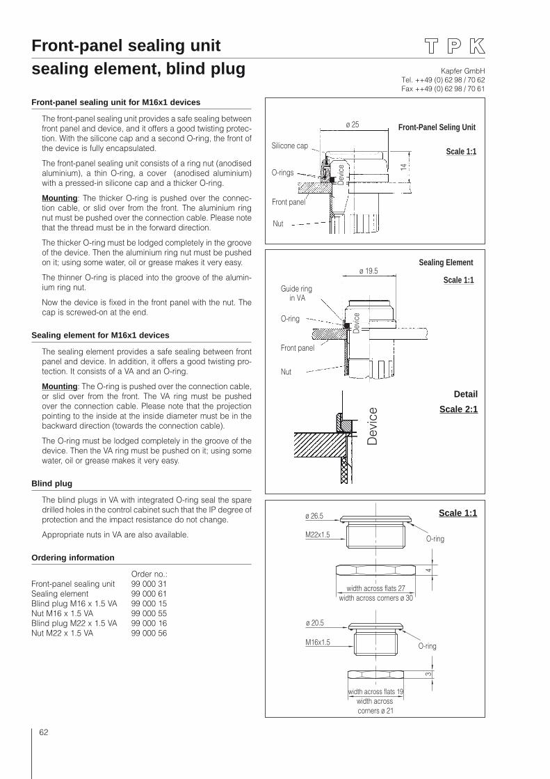
Kapfer GmbHTel. ++49 (0) 62 98 / 70 62Fax ++49 (0) 62 98 / 70 61
62
Front-panel sealing unit sealing element, blind plug
Front-panel sealing unit for M16x1 devices
The front-panel sealing unit provides a safe sealing between front panel and device, and it offers a good twisting protec-tion. With the silicone cap and a second O-ring, the front of the device is fully encapsulated.
The front-panel sealing unit consists of a ring nut (anodised aluminium), a thin O-ring, a cover (anodised aluminium) with a pressed-in silicone cap and a thicker O-ring.
Mounting: The thicker O-ring is pushed over the connec-tion cable, or slid over from the front. The aluminium ring nut must be pushed over the connection cable. Please note that the thread must be in the forward direction.
The thicker O-ring must be lodged completely in the groove of the device. Then the aluminium ring nut must be pushed on it; using some water, oil or grease makes it very easy.
The thinner O-ring is placed into the groove of the alumin-ium ring nut.
Now the device is fixed in the front panel with the nut. The cap is screwed-on at the end.
Sealing element for M16x1 devices
The sealing element provides a safe sealing between front panel and device. In addition, it offers a good twisting pro-tection. It consists of a VA and an O-ring.
Mounting: The O-ring is pushed over the connection cable, or slid over from the front. The VA ring must be pushed over the connection cable. Please note that the projection pointing to the inside at the inside diameter must be in the backward direction (towards the connection cable).
The O-ring must be lodged completely in the groove of the device. Then the VA ring must be pushed on it; using some water, oil or grease makes it very easy.
Blind plug
The blind plugs in VA with integrated O-ring seal the spare drilled holes in the control cabinet such that the IP degree of protection and the impact resistance do not change.
Appropriate nuts in VA are also available.
Ordering information
Order no.:Front-panel sealing unit 99 000 31Sealing element 99 000 61Blind plug M16 x 1.5 VA 99 000 15Nut M16 x 1.5 VA 99 000 55Blind plug M22 x 1.5 VA 99 000 16Nut M22 x 1.5 VA 99 000 56
50
Nut
Front panel
O-rings
Silicone cap
ø 25
Devic
e 14
Front-Panel Seling Unit
Scale 1:1
ø 19.5Sealing Element
Guide ringin VA
O-ring
Front panel
Nut
Devic
e
Scale 1:1
Dev
ice
Detail
Scale 2:1
4
ø 26.5
3
M22x1.5
M16x1.5
ø 20.5
width across flats 19width across corners ø 21
width across flats 27width across corners ø 30
O-ring
O-ring
Scale 1:1
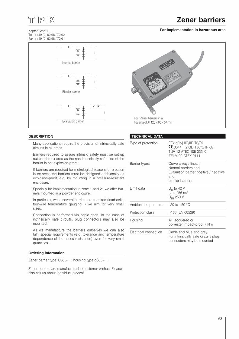
Kapfer GmbHTel. ++49 (0) 62 98 / 70 62Fax ++49 (0) 62 98 / 70 61
63
Zener barriersFor implementation in hazardous area
DESCRIPTION
Many applications require the provision of intrinsically safe circuits in ex-areas.
Barriers required to assure intrinsic safety must be set up outside the ex-area as the non-intrinsically safe side of the barrier is not explosion-proof.
If barriers are required for metrological reasons or erection in ex-areas the barriers must be designed additionally as explosion-proof, e.g. by mounting in a pressure-resistant enclosure.
Specially for implementation in zone 1 and 21 we offer bar-riers mounted in a powder enclosure.
In particular, when several barriers are required (load cells, four-wire temperature gauging...) we aim for very small sizes.
Connection is performed via cable ends. In the case of intrinsically safe circuits, plug connectors may also be mounted.
As we manufacture the barriers ourselves we can also fulfil special requirements (e.g. tolerance and temperature dependence of the series resistance) even for very small quantities.
Ordering information
Zener barrier type iU35L-....; housing type qS33.-....
Zener barriers are manufactured to customer wishes. Please also ask us about individual pieces!
TECHNICAL DATA
Type of protection EEx q[ib] IIC/IIB T6/T5 0044 II 2 GD T80°C IP 68 TÜV 12 ATEX 108 033 X ZELM 02 ATEX 0111
Barrier types Curve always linear; Normal barriers and Evaluation barrier positive / negative and bipolar barriers
Limit data Uo to 42 V Io to 456 mA Um 250 V
Ambient temperature –20 to +50 °C
Protection class IP 68 (EN 60529)
Housing Al, lacquered or polyester impact-proof 7 Nm
Electrical connection Cable end blue and grey For intrinsically safe circuits plug connectors may be mounted
i
i
i
Normal barrier
Bipolar barrier
Evaluation barrierFour Zener barriers in ahousing of Al 125 x 80 x 57 mm
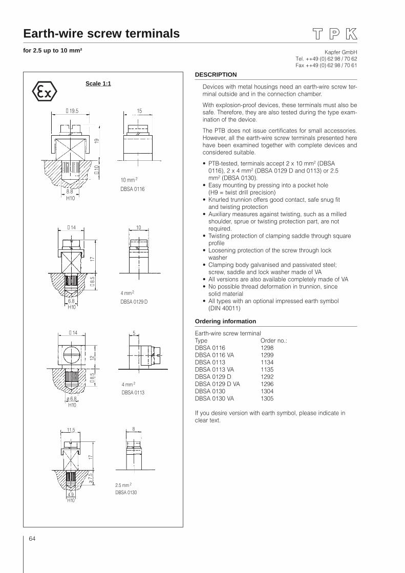
Kapfer GmbHTel. ++49 (0) 62 98 / 70 62Fax ++49 (0) 62 98 / 70 61
64
Earth-wire screw terminalsfor 2.5 up to 10 mm²
DESCRIPTION
Devices with metal housings need an earth-wire screw ter-minal outside and in the connection chamber.
With explosion-proof devices, these terminals must also be safe. Therefore, they are also tested during the type exam-ination of the device.
The PTB does not issue certificates for small accessories. However, all the earth-wire screw terminals presented here have been examined together with complete devices and considered suitable.
• PTB-tested, terminals accept 2 x 10 mm² (DBSA 0116), 2 x 4 mm² (DBSA 0129 D and 0113) or 2.5 mm² (DBSA 0130).
• Easy mounting by pressing into a pocket hole (H9 = twist drill precision)
• Knurled trunnion offers good contact, safe snug fit and twisting protection
• Auxiliary measures against twisting, such as a milled shoulder, sprue or twisting protection part, are not required.
• Twisting protection of clamping saddle through square profile
• Loosening protection of the screw through lock washer
• Clamping body galvanised and passivated steel; screw, saddle and lock washer made of VA
• All versions are also available completely made of VA• No possible thread deformation in trunnion, since
solid material• All types with an optional impressed earth symbol
(DIN 40011)
Ordering information
Earth-wire screw terminal Type Order no.:DBSA 0116 1298DBSA 0116 VA 1299DBSA 0113 1134DBSA 0113 VA 1135DBSA 0129 D 1292DBSA 0129 D VA 1296DBSA 0130 1304DBSA 0130 VA 1305
If you desire version with earth symbol, please indicate in clear text.
≤ 14 10
17≥ 8
.5
6.8H10
4 mm 2
DBSA 0129 D
≤ 14 5
12≥ 8
.5
ø 6.8H10
4 mm 2
DBSA 0113
11.5 8
17≥ 7
.5
4.9H10
2.5 mm 2
DBSA 0130
Scale 1:1
≤ 19.5 15
19≥ 1
0
8.8H10
10 mm 2
DBSA 0116
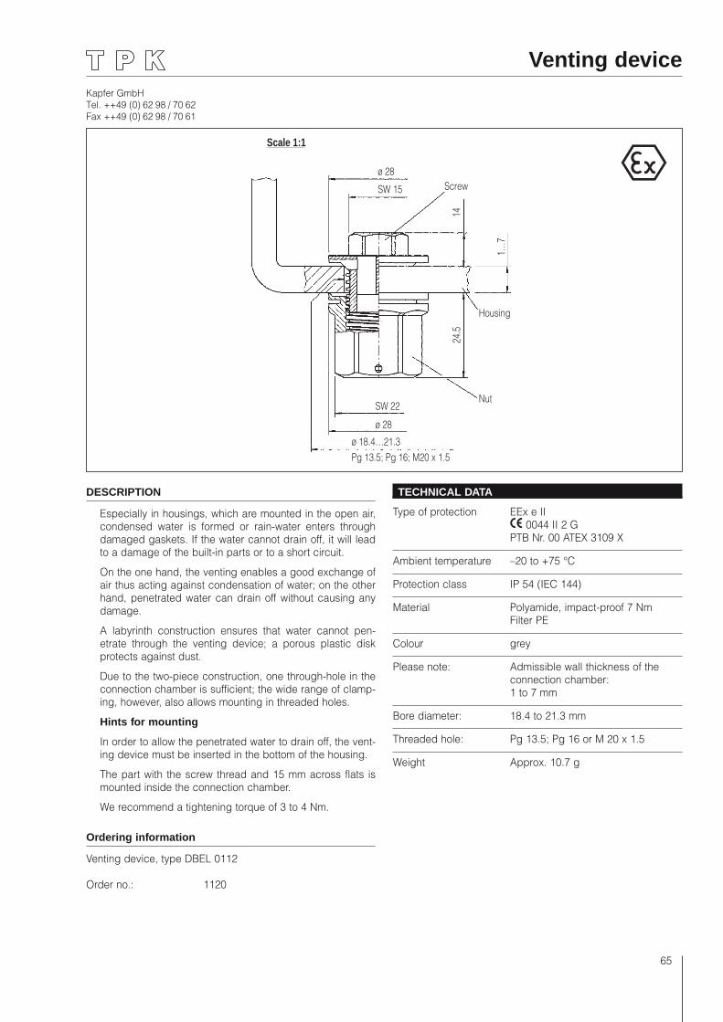
Kapfer GmbHTel. ++49 (0) 62 98 / 70 62Fax ++49 (0) 62 98 / 70 61
65
Venting device
Scale 1:1
ø 28
SW 15 Screw
14
1…7
Housing
24.5
NutSW 22
ø 28
ø 18.4…21.3Pg 13.5; Pg 16; M20 x 1.5
DESCRIPTION
Especially in housings, which are mounted in the open air, condensed water is formed or rain-water enters through damaged gaskets. If the water cannot drain off, it will lead to a damage of the built-in parts or to a short circuit.
On the one hand, the venting enables a good exchange of air thus acting against condensation of water; on the other hand, penetrated water can drain off without causing any damage.
A labyrinth construction ensures that water cannot pen-etrate through the venting device; a porous plastic disk protects against dust.
Due to the two-piece construction, one through-hole in the connection chamber is sufficient; the wide range of clamp-ing, however, also allows mounting in threaded holes.
Hints for mounting
In order to allow the penetrated water to drain off, the vent-ing device must be inserted in the bottom of the housing.
The part with the screw thread and 15 mm across flats is mounted inside the connection chamber.
We recommend a tightening torque of 3 to 4 Nm.
Ordering information
Venting device, type DBEL 0112
Order no.: 1120
TECHNICAL DATA
Type of protection EEx e II 0044 II 2 G PTB Nr. 00 ATEX 3109 X
Ambient temperature –20 to +75 °C
Protection class IP 54 (IEC 144)
Material Polyamide, impact-proof 7 Nm Filter PE
Colour grey
Please note: Admissible wall thickness of the connection chamber: 1 to 7 mm
Bore diameter: 18.4 to 21.3 mm
Threaded hole: Pg 13.5; Pg 16 or M 20 x 1.5
Weight Approx. 10.7 g
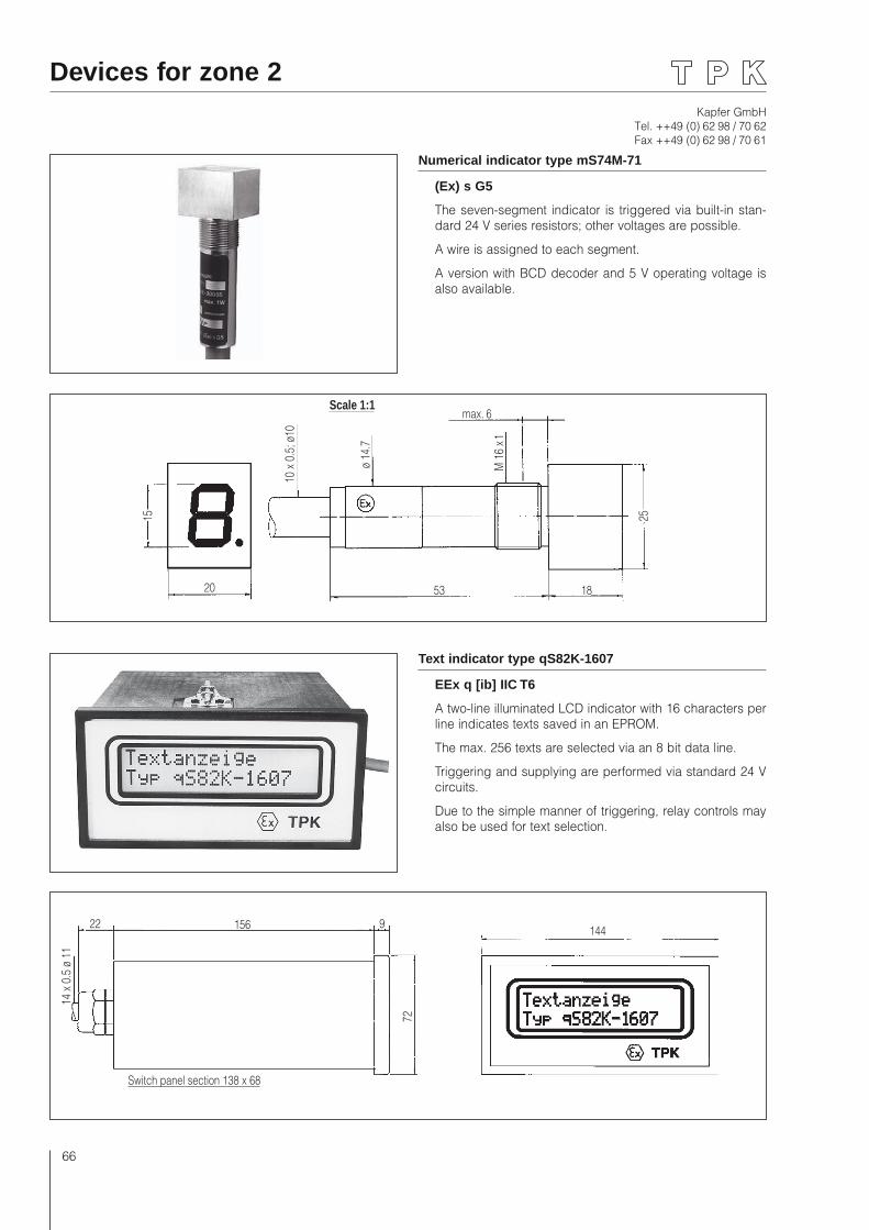
Kapfer GmbHTel. ++49 (0) 62 98 / 70 62Fax ++49 (0) 62 98 / 70 61
66
Devices for zone 2
20
Scale 1:1
53
15
ø 14
.7
10 x
0.5
; ø10
max. 6
M 1
6 x 1
18
25
Numerical indicator type mS74M-71
(Ex) s G5
The seven-segment indicator is triggered via built-in stan-dard 24 V series resistors; other voltages are possible.
A wire is assigned to each segment.
A version with BCD decoder and 5 V operating voltage is also available.
22 156 9
Switch panel section 138 x 68
72
14 x
0.5
ø 1
1
Text indicator type qS82K-1607
EEx q [ib] IIC T6
A two-line illuminated LCD indicator with 16 characters per line indicates texts saved in an EPROM.
The max. 256 texts are selected via an 8 bit data line.
Triggering and supplying are performed via standard 24 V circuits.
Due to the simple manner of triggering, relay controls may also be used for text selection.
144
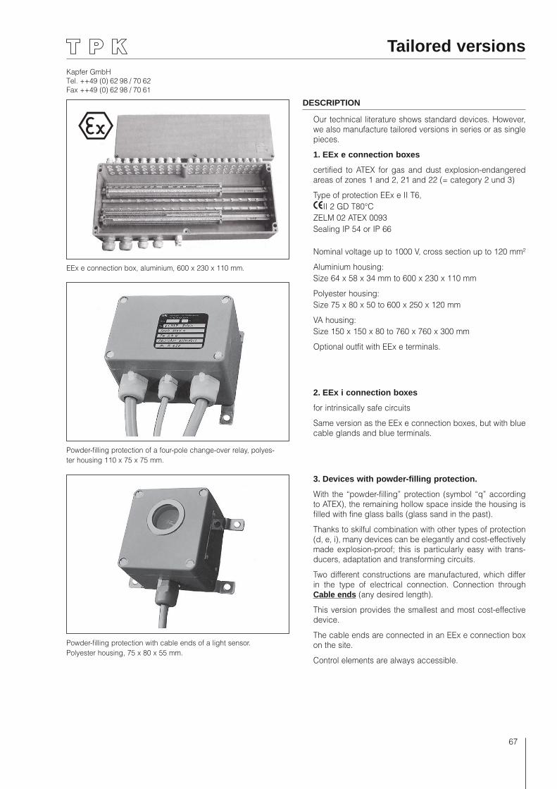
Kapfer GmbHTel. ++49 (0) 62 98 / 70 62Fax ++49 (0) 62 98 / 70 61
67
Tailored versions
DESCRIPTION
Our technical literature shows standard devices. However, we also manufacture tailored versions in series or as single pieces.
1. EEx e connection boxes
certified to ATEX for gas and dust explosion-endangered areas of zones 1 and 2, 21 and 22 (= category 2 und 3)
Type of protection EEx e II T6,II 2 GD T80°C
ZELM 02 ATEX 0093Sealing IP 54 or IP 66
Nominal voltage up to 1000 V, cross section up to 120 mm²
Aluminium housing:Size 64 x 58 x 34 mm to 600 x 230 x 110 mm
Polyester housing:Size 75 x 80 x 50 to 600 x 250 x 120 mm
VA housing:Size 150 x 150 x 80 to 760 x 760 x 300 mm
Optional outfit with EEx e terminals.
2. EEx i connection boxes
for intrinsically safe circuits
Same version as the EEx e connection boxes, but with blue cable glands and blue terminals.
3. Devices with powder-filling protection.
With the “powder-filling” protection (symbol “q” according to ATEX), the remaining hollow space inside the housing is filled with fine glass balls (glass sand in the past).
Thanks to skilful combination with other types of protection (d, e, i), many devices can be elegantly and cost-effectively made explosion-proof; this is particularly easy with trans-ducers, adaptation and transforming circuits.
Two different constructions are manufactured, which differ in the type of electrical connection. Connection through Cable ends (any desired length).
This version provides the smallest and most cost-effective device.
The cable ends are connected in an EEx e connection box on the site.
Control elements are always accessible.
Powder-filling protection with cable ends of a light sensor. Polyester housing, 75 x 80 x 55 mm.
EEx e connection box, aluminium, 600 x 230 x 110 mm.
Powder-filling protection of a four-pole change-over relay, polyes-ter housing 110 x 75 x 75 mm.
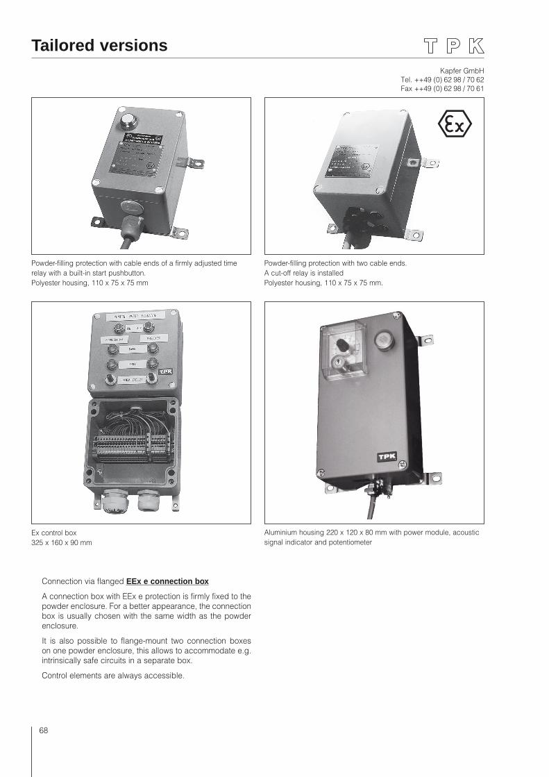
Kapfer GmbHTel. ++49 (0) 62 98 / 70 62Fax ++49 (0) 62 98 / 70 61
68
Tailored versions
Powder-filling protection with cable ends of a firmly adjusted time relay with a built-in start pushbutton. Polyester housing, 110 x 75 x 75 mm
Ex control box 325 x 160 x 90 mm
Powder-filling protection with two cable ends. A cut-off relay is installed Polyester housing, 110 x 75 x 75 mm.
Aluminium housing 220 x 120 x 80 mm with power module, acoustic signal indicator and potentiometer
Connection via flanged EEx e connection box
A connection box with EEx e protection is firmly fixed to the powder enclosure. For a better appearance, the connection box is usually chosen with the same width as the powder enclosure.
It is also possible to flange-mount two connection boxes on one powder enclosure, this allows to accommodate e.g. intrinsically safe circuits in a separate box.
Control elements are always accessible.

Kapfer GmbHTel. ++49 (0) 62 98 / 70 62Fax ++49 (0) 62 98 / 70 61
69
Tailored versions
Ex control box 360 x 160 x 90 mm
Ex control box 260 x 160 x 90 mm
Ex control box made of polyester, with flanged connection box, overall dimensions 560 x 325 x 90 mm.
Ex control box made of polyester, with flanged connection box, overall dimensions 560 x 325 x 90 mm.
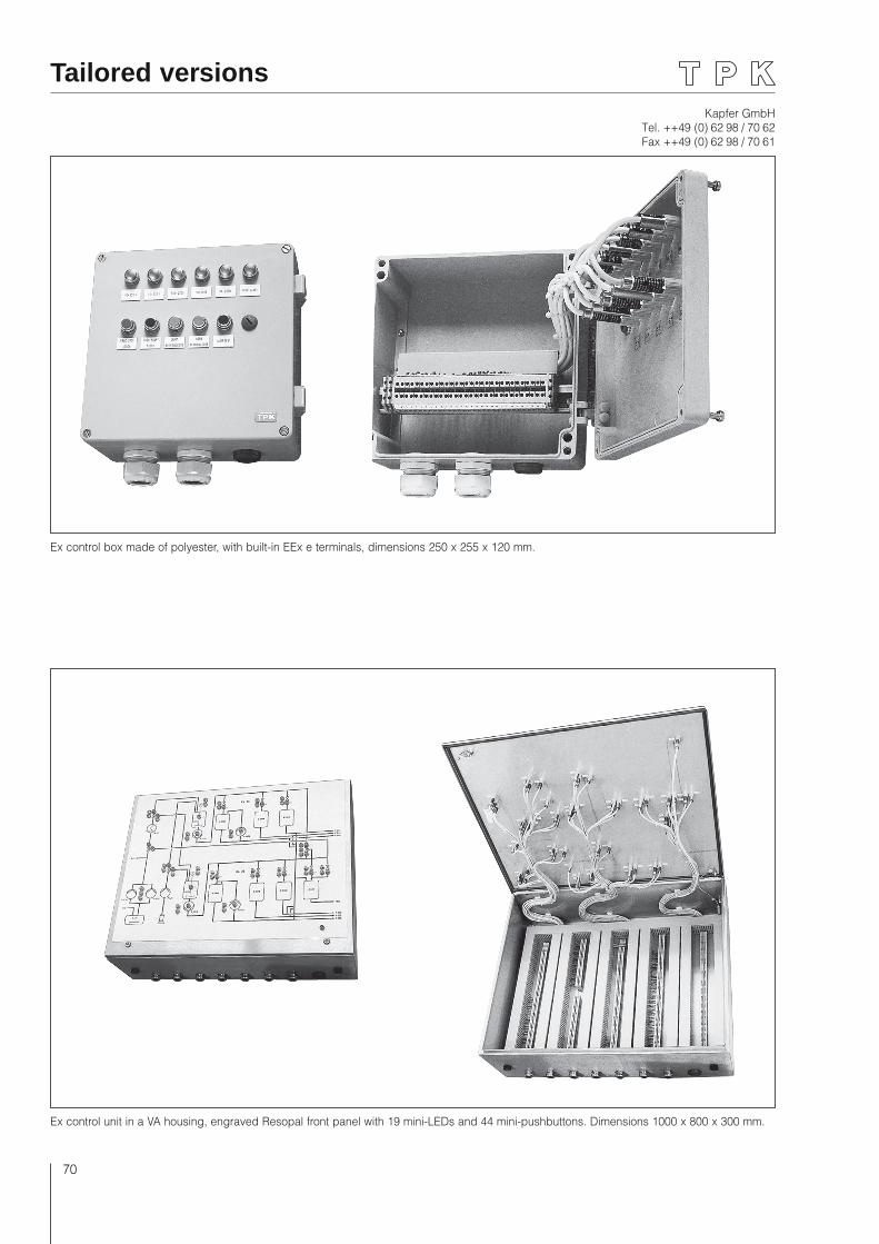
Kapfer GmbHTel. ++49 (0) 62 98 / 70 62Fax ++49 (0) 62 98 / 70 61
70
Ex control unit in a VA housing, engraved Resopal front panel with 19 mini-LEDs and 44 mini-pushbuttons. Dimensions 1000 x 800 x 300 mm.
Ex control box made of polyester, with built-in EEx e terminals, dimensions 250 x 255 x 120 mm.
Tailored versions
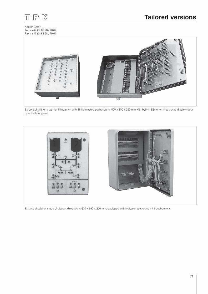
Kapfer GmbHTel. ++49 (0) 62 98 / 70 62Fax ++49 (0) 62 98 / 70 61
71
Ex-control unit for a varnish filling plant with 36 illuminated pushbuttons, 800 x 800 x 250 mm with built-in EEx-e terminal box and safety door over the front panel.
Ex control cabinet made of plastic, dimensions 600 x 350 x 250 mm, equipped with indicator lamps and mini-pushbuttons.
Tailored versions

Kapfer GmbHTel. ++49 (0) 62 98 / 70 62Fax ++49 (0) 62 98 / 70 61
72
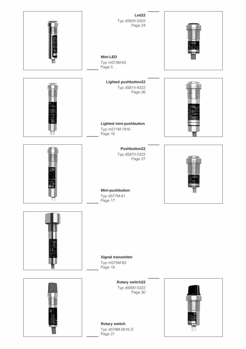
Mini-LED
Typ mS73M-65 Page 5
Signal transmitter
Typ mS75M-83 Page 18
Mini-pushbutton
Typ dS77M-81 Page 17
Rotary switch
Typ dS79M-5616 D Page 21
Lighted mini-pushbutton
Typ mS71M-7916 Page 16
Mini step switch
Typ dS79M-5716 D Page 22
Keylock switch
Typ dS79M-7616 DS Page 20
10-turn mini-potentiometer
Typ dS79M-7716 P Page 36
Mini-potentiometer
Typ dS79M-5516 P Page 35
Led22
Typ dS83V-5322 Page 24
Pushbutton22
Typ dS87V-5322 Page 27
Rotary switch22
Typ dS89V-5322 Page 30
Lighted pushbutton22
Typ dS81V-8322 Page 26
Keylock switch22
Typ dS89V-6622 Page 31
LedSpotlight
Typ dS64V-7329 Page 11

Explosion-Proof Devices 2015 / 2016
TPK Kapfer GmbHSchillerstraße 13D-74219 MöckmühlTel. ++49 (0) 62 98 / 70 62Fax ++49 (0) 62 98 / 70 61
TPK Kapfer GmbHSchillerstraße 13D-74219 MöckmühlTel. ++49 (0) 62 98 / 70 62Fax ++49 (0) 62 98 / 70 61
Recommended